


DSX-40
Table of contents
 Loading...
Empowered by Innovation
Components Installation
Equipment
Optional
Specifications
and Parts
DSX-40 Hardware Manual
For additional resources, visit our Technical Support site on the web at
P/N 1093097
Rev 1, October 2006
http://www.necdsx.com
Printed in U.S.A
01.01.09
.
.

This manual has been developed by NEC Unified Solutions, Inc. It is intended for the use of its customers and service
personnel, and should be read in its entirety before attempting to install or program the system. Any comments or suggestions
for improving this manual would be appreciated. Forward your remarks to:
NEC Unified Solutions, Inc.
4 Forest Parkway
Shelton, CT 06484
www.necunifiedsolutions.com
Nothing contained in this manual shall be deemed to be, and this manual does not constitute, a warranty of, or representation
with respect to, any of the equipment covered. This manual is subject to change without notice and NEC Unified Solutions,
Inc. has no obligation to provide any updates or corrections to this manual. Further, NEC Unified Solutions, Inc. also reserves
the right, without prior notice, to make changes in equipment design or components as it deems appropriate. No
representation is made that this manual is complete or accurate in all respects and NEC Unified Solutions, Inc. shall not be
liable for any errors or omissions. In no event shall NEC Unified Solutions, Inc. be liable for any incidental or consequential
damages in connection with the use of this manual. This document contains proprietary information that is protected by
copyright. All rights are reserved. No part of this document may be photocopied or reproduced without prior written consent
of NEC Unified Solutions, Inc.
©2006 by NEC Unified Solutions, Inc. All Rights Reserved.
Printed in U.S.A.

Table of Contents
Table of Contents
Components . . . . . . . . . . . . . . . . . . . . . . . . . . . . . . . . . . . . . . . . . . . . . . . . . . . . . . . . . . 1
DSX Telephones . . . . . . . . . . . . . . . . . . . . . . . . . . . . . . . . . . . . . . . . . . . . . . . . . . . . . . . . 1
22-Button Display Telephone with Speakerphone. . . . . . . . . . . . . . . . . . . . . . . . . . . . . . . . . . . 1
34-Button Backlit Display Telephone with Speakerphone . . . . . . . . . . . . . . . . . . . . . . . . . . . . 1
34-Button Backlit Display Telephone with Full-Duplex Speakerphone . . . . . . . . . . . . . . . . . . 2
34-Button Backlit Super Display Telephone with Half-Duplex Speakerphone . . . . . . . . . . . . . 2
60-Button DSS Console . . . . . . . . . . . . . . . . . . . . . . . . . . . . . . . . . . . . . . . . . . . . . . . . . . . . . . . 2
Single Line Telephones . . . . . . . . . . . . . . . . . . . . . . . . . . . . . . . . . . . . . . . . . . . . . . . . . . . 3
DTH-1-1 Single Line Telephone . . . . . . . . . . . . . . . . . . . . . . . . . . . . . . . . . . . . . . . . . . . . . . . . 3
DTR-1-1 Single Line Telephone . . . . . . . . . . . . . . . . . . . . . . . . . . . . . . . . . . . . . . . . . . . . . . . . 3
DTR-1HM-1 Single Line Telephone . . . . . . . . . . . . . . . . . . . . . . . . . . . . . . . . . . . . . . . . . . . . . 3
DSX Cordless Telephone. . . . . . . . . . . . . . . . . . . . . . . . . . . . . . . . . . . . . . . . . . . . . . . . . . 4
DSX Cordless Lite II . . . . . . . . . . . . . . . . . . . . . . . . . . . . . . . . . . . . . . . . . . . . . . . . . . . . . . . . . 4
Headsets . . . . . . . . . . . . . . . . . . . . . . . . . . . . . . . . . . . . . . . . . . . . . . . . . . . . . . . . . . . . . . . 5
Corded Headsets for DSX Keysets and DTR/DTH SLTs . . . . . . . . . . . . . . . . . . . . . . . . . . . . . 5
NEC / Plantronics Headsets . . . . . . . . . . . . . . . . . . . . . . . . . . . . . . . . . . . . . . . . . . . . . . . . . 5
GN Netcom Headsets . . . . . . . . . . . . . . . . . . . . . . . . . . . . . . . . . . . . . . . . . . . . . . . . . . . . . . 8
Headsets for DSX Cordless Lite II Telephone. . . . . . . . . . . . . . . . . . . . . . . . . . . . . . . . . . . . . . 9
DESI Telephone Label System . . . . . . . . . . . . . . . . . . . . . . . . . . . . . . . . . . . . . . . . . . . . 10
DESI Plus Labeling Software. . . . . . . . . . . . . . . . . . . . . . . . . . . . . . . . . . . . . . . . . . . . . . . . . . 10
DESI Telephone Labels . . . . . . . . . . . . . . . . . . . . . . . . . . . . . . . . . . . . . . . . . . . . . . . . . . . . . . 11
DSX-40 Common Equipment . . . . . . . . . . . . . . . . . . . . . . . . . . . . . . . . . . . . . . . . . . . . . 12
DSX-40 4x8x2 Key Telephone System with 2 Door Box Ports and Caller-ID . . . . . . . . . . . . 12
DSX-40 PCBs . . . . . . . . . . . . . . . . . . . . . . . . . . . . . . . . . . . . . . . . . . . . . . . . . . . . . . . . . 13
DSX-40 8-Port Digital Station (8ESIU) Card . . . . . . . . . . . . . . . . . . . . . . . . . . . . . . . . . . . . . 13
Expansion Guidelines . . . . . . . . . . . . . . . . . . . . . . . . . . . . . . . . . . . . . . . . . . . . . . . . . . . . . 13
DSX-40 8-Port Analog Station (8SLIU) Card . . . . . . . . . . . . . . . . . . . . . . . . . . . . . . . . . . . . . 13
DSX-40 4 Port (4COIU) Line PCB with Caller ID . . . . . . . . . . . . . . . . . . . . . . . . . . . . . . . . . 14
IntraMail . . . . . . . . . . . . . . . . . . . . . . . . . . . . . . . . . . . . . . . . . . . . . . . . . . . . . . . . . . . . . 15
DSX IntraMail 8 x 16. . . . . . . . . . . . . . . . . . . . . . . . . . . . . . . . . . . . . . . . . . . . . . . . . . . . . . . . 15
DSX IntraMail 4 x 8. . . . . . . . . . . . . . . . . . . . . . . . . . . . . . . . . . . . . . . . . . . . . . . . . . . . . . . . . 15
Built-In Automated Attendant . . . . . . . . . . . . . . . . . . . . . . . . . . . . . . . . . . . . . . . . . . . . . . . . . 15
Miscellaneous Cards and Optional Equipment . . . . . . . . . . . . . . . . . . . . . . . . . . . . . . . . 16
DSX Analog Door Box . . . . . . . . . . . . . . . . . . . . . . . . . . . . . . . . . . . . . . . . . . . . . . . . . . . . . . 16
DSX 2PGDAD Module . . . . . . . . . . . . . . . . . . . . . . . . . . . . . . . . . . . . . . . . . . . . . . . . . . . . . . 16
DSX System Administrator (PC Program) . . . . . . . . . . . . . . . . . . . . . . . . . . . . . . . . . . . . . . . 17
Installation . . . . . . . . . . . . . . . . . . . . . . . . . . . . . . . . . . . . . . . . . . . . . . . . . . . . . . . . . . 19
System Preparation . . . . . . . . . . . . . . . . . . . . . . . . . . . . . . . . . . . . . . . . . . . . . . . . . . . . . 19
Installing the Main Equipment Cabinet . . . . . . . . . . . . . . . . . . . . . . . . . . . . . . . . . . . . . . 20
Grounding the Cabinet. . . . . . . . . . . . . . . . . . . . . . . . . . . . . . . . . . . . . . . . . . . . . . . . . . . 23
DSX-40 Hardware Manual
Unpacking . . . . . . . . . . . . . . . . . . . . . . . . . . . . . . . . . . . . . . . . . . . . . . . . . . . . . . . . . . . . . . . . 19
Before Installing. . . . . . . . . . . . . . . . . . . . . . . . . . . . . . . . . . . . . . . . . . . . . . . . . . . . . . . . . . . . 19
Site Requirements. . . . . . . . . . . . . . . . . . . . . . . . . . . . . . . . . . . . . . . . . . . . . . . . . . . . . . . . . . . 19
Single Line Telephone REN Limitations . . . . . . . . . . . . . . . . . . . . . . . . . . . . . . . . . . . . . . . . . 19
Planning the Installation. . . . . . . . . . . . . . . . . . . . . . . . . . . . . . . . . . . . . . . . . . . . . . . . . . . . . . 20
Removing the Cover. . . . . . . . . . . . . . . . . . . . . . . . . . . . . . . . . . . . . . . . . . . . . . . . . . . . . . . . . 21
Hanging the Cabinet. . . . . . . . . . . . . . . . . . . . . . . . . . . . . . . . . . . . . . . . . . . . . . . . . . . . . . . . . 22
Table of Contents ◆ i

ii ◆
Table of Contents
Removing the Top Panel . . . . . . . . . . . . . . . . . . . . . . . . . . . . . . . . . . . . . . . . . . . . . . . . . 24
Installing Expansion Cards, the Battery, and Replacement Fuses. . . . . . . . . . . . . . . . . . 25
Connecting Extensions and Lines . . . . . . . . . . . . . . . . . . . . . . . . . . . . . . . . . . . . . . . . . . 28
Setting Up the Telephone and DSS Console . . . . . . . . . . . . . . . . . . . . . . . . . . . . . . . . . . 36
Powering Up the System . . . . . . . . . . . . . . . . . . . . . . . . . . . . . . . . . . . . . . . . . . . . . . . . . 41
Finishing the Installation . . . . . . . . . . . . . . . . . . . . . . . . . . . . . . . . . . . . . . . . . . . . . . . . . 43
Resetting and Initializing the System . . . . . . . . . . . . . . . . . . . . . . . . . . . . . . . . . . . . . . . 44
Upgrading the System Software . . . . . . . . . . . . . . . . . . . . . . . . . . . . . . . . . . . . . . . . . . . 46
Attaching the Ground Wire . . . . . . . . . . . . . . . . . . . . . . . . . . . . . . . . . . . . . . . . . . . . . . . . . . . 23
Top Panel Removal . . . . . . . . . . . . . . . . . . . . . . . . . . . . . . . . . . . . . . . . . . . . . . . . . . . . . . . . . 24
Installing Expansion Cards. . . . . . . . . . . . . . . . . . . . . . . . . . . . . . . . . . . . . . . . . . . . . . . . . . . . 25
Station Cards. . . . . . . . . . . . . . . . . . . . . . . . . . . . . . . . . . . . . . . . . . . . . . . . . . . . . . . . . . . . 25
Line Card . . . . . . . . . . . . . . . . . . . . . . . . . . . . . . . . . . . . . . . . . . . . . . . . . . . . . . . . . . . . . . 25
Installing and Replacing the Battery . . . . . . . . . . . . . . . . . . . . . . . . . . . . . . . . . . . . . . . . . . . . 26
Power Supply AC Input Fuses . . . . . . . . . . . . . . . . . . . . . . . . . . . . . . . . . . . . . . . . . . . . . . . . . 27
Extension and Line Connections . . . . . . . . . . . . . . . . . . . . . . . . . . . . . . . . . . . . . . . . . . . . . . . 28
Punch Down for Extensions . . . . . . . . . . . . . . . . . . . . . . . . . . . . . . . . . . . . . . . . . . . . . . . . 30
Punch Down for Lines . . . . . . . . . . . . . . . . . . . . . . . . . . . . . . . . . . . . . . . . . . . . . . . . . . . . 31
Securing the Cables . . . . . . . . . . . . . . . . . . . . . . . . . . . . . . . . . . . . . . . . . . . . . . . . . . . . . . . . . 32
Securing the Ground Wires and Station Cables . . . . . . . . . . . . . . . . . . . . . . . . . . . . . . . . . 32
Securing the AC Power Cord . . . . . . . . . . . . . . . . . . . . . . . . . . . . . . . . . . . . . . . . . . . . . . . 32
Making Your Own Cables . . . . . . . . . . . . . . . . . . . . . . . . . . . . . . . . . . . . . . . . . . . . . . . . . . . . 33
Making Your Own Installation Cables. . . . . . . . . . . . . . . . . . . . . . . . . . . . . . . . . . . . . . . . 33
Connecting Extensions. . . . . . . . . . . . . . . . . . . . . . . . . . . . . . . . . . . . . . . . . . . . . . . . . . . . . . . 33
Connecting Lines . . . . . . . . . . . . . . . . . . . . . . . . . . . . . . . . . . . . . . . . . . . . . . . . . . . . . . . . . . . 35
Installing the DSX Keyset Handset and Line Cord.. . . . . . . . . . . . . . . . . . . . . . . . . . . . . . . . . 36
Installing the DSX Keyset Optional Headset . . . . . . . . . . . . . . . . . . . . . . . . . . . . . . . . . . . . . . 36
Installing the DSS Console Line Cord . . . . . . . . . . . . . . . . . . . . . . . . . . . . . . . . . . . . . . . . . . . 37
Keyset and DSS Console Two Position Angle Adjustment. . . . . . . . . . . . . . . . . . . . . . . . . . . 38
Removing the Faceplate . . . . . . . . . . . . . . . . . . . . . . . . . . . . . . . . . . . . . . . . . . . . . . . . . . . . . . 39
Power Up . . . . . . . . . . . . . . . . . . . . . . . . . . . . . . . . . . . . . . . . . . . . . . . . . . . . . . . . . . . . . . . . . 41
Reinstalling the Cover . . . . . . . . . . . . . . . . . . . . . . . . . . . . . . . . . . . . . . . . . . . . . . . . . . . . . . . 43
Resetting the System . . . . . . . . . . . . . . . . . . . . . . . . . . . . . . . . . . . . . . . . . . . . . . . . . . . . . . . . 44
Initializing the System . . . . . . . . . . . . . . . . . . . . . . . . . . . . . . . . . . . . . . . . . . . . . . . . . . . . . . . 45
Upgrade System Software . . . . . . . . . . . . . . . . . . . . . . . . . . . . . . . . . . . . . . . . . . . . . . . . . . . . 46
Installing Optional Equipment . . . . . . . . . . . . . . . . . . . . . . . . . . . . . . . . . . . . . . . . . . 47
Installing IntraMail . . . . . . . . . . . . . . . . . . . . . . . . . . . . . . . . . . . . . . . . . . . . . . . . . . . . . 47
Installing a DSX Analog Door Box on a Built-In Door Box Port . . . . . . . . . . . . . . . . . . 49
Installing a DSX Analog Door Box and 2PGDAD Module . . . . . . . . . . . . . . . . . . . . . . 51
External Paging . . . . . . . . . . . . . . . . . . . . . . . . . . . . . . . . . . . . . . . . . . . . . . . . . . . . . . . . 54
Music Source . . . . . . . . . . . . . . . . . . . . . . . . . . . . . . . . . . . . . . . . . . . . . . . . . . . . . . . . . . 55
Power Failure Telephone . . . . . . . . . . . . . . . . . . . . . . . . . . . . . . . . . . . . . . . . . . . . . . . . . 56
Table of Contents
Setting Up IntraMail for the First Time . . . . . . . . . . . . . . . . . . . . . . . . . . . . . . . . . . . . . . . . . . 47
Connecting a DSX Analog Door Box to a Built-In Door Box Port . . . . . . . . . . . . . . . . . . . . . 49
Connecting a DSX Analog Door Box to the 2PGDAD Module . . . . . . . . . . . . . . . . . . . . . . . 51
Preparation . . . . . . . . . . . . . . . . . . . . . . . . . . . . . . . . . . . . . . . . . . . . . . . . . . . . . . . . . . . . . 51
Connecting PGDAD Door Boxes and Relays . . . . . . . . . . . . . . . . . . . . . . . . . . . . . . . . . . 52
Mounting the 2PGDAD Module and Connecting to the System . . . . . . . . . . . . . . . . . . . . 53
Installing External Paging . . . . . . . . . . . . . . . . . . . . . . . . . . . . . . . . . . . . . . . . . . . . . . . . . . . . 54
Installing a Music Source. . . . . . . . . . . . . . . . . . . . . . . . . . . . . . . . . . . . . . . . . . . . . . . . . . . . . 55
DSX-40 Hardware Manual

Table of Contents
Power Failure Cut-Through . . . . . . . . . . . . . . . . . . . . . . . . . . . . . . . . . . . . . . . . . . . . . . . . . . . 56
Wall Mounting . . . . . . . . . . . . . . . . . . . . . . . . . . . . . . . . . . . . . . . . . . . . . . . . . . . . . . . . . 57
Reversing the Handset Hanger . . . . . . . . . . . . . . . . . . . . . . . . . . . . . . . . . . . . . . . . . . . . . . . . . 57
Wall Mounting a Keyset. . . . . . . . . . . . . . . . . . . . . . . . . . . . . . . . . . . . . . . . . . . . . . . . . . . . . . 58
Wall Mounting a Keyset on a Standard Wall Plate . . . . . . . . . . . . . . . . . . . . . . . . . . . . . . 58
Wall Mounting a Keyset Directly on the Wall . . . . . . . . . . . . . . . . . . . . . . . . . . . . . . . . . . 59
Wall Mounting a DSS Console . . . . . . . . . . . . . . . . . . . . . . . . . . . . . . . . . . . . . . . . . . . . . . . . 60
Wall Mounting a DSS Console on a Standard Wall Plate . . . . . . . . . . . . . . . . . . . . . . . . . 60
Wall Mounting a DSS Console Directly on the Wall. . . . . . . . . . . . . . . . . . . . . . . . . . . . . 61
Keyset Self Test . . . . . . . . . . . . . . . . . . . . . . . . . . . . . . . . . . . . . . . . . . . . . . . . . . . . . . . . 62
Testing the Keyset . . . . . . . . . . . . . . . . . . . . . . . . . . . . . . . . . . . . . . . . . . . . . . . . . . . . . . . . . . 62
Connecting a PC to the System . . . . . . . . . . . . . . . . . . . . . . . . . . . . . . . . . . . . . . . . . . . . 63
Connections for PC Programming (System Administrator) and SMDR . . . . . . . . . . . . . . . . . 63
Specifications and Parts . . . . . . . . . . . . . . . . . . . . . . . . . . . . . . . . . . . . . . . . . . . . . . . 65
Specifications. . . . . . . . . . . . . . . . . . . . . . . . . . . . . . . . . . . . . . . . . . . . . . . . . . . . . . . . . . 65
DSX Telephone System Specifications . . . . . . . . . . . . . . . . . . . . . . . . . . . . . . . . . . . . . . . . . . 65
DSX IntraMail Specifications . . . . . . . . . . . . . . . . . . . . . . . . . . . . . . . . . . . . . . . . . . . . . . . . . 70
Parts List . . . . . . . . . . . . . . . . . . . . . . . . . . . . . . . . . . . . . . . . . . . . . . . . . . . . . . . . . . . . . 71
DSX-40 Hardware Manual
Table of Contents ◆ iii

Table of Contents
iv ◆
Table of Contents
DSX-40 Hardware Manual
DSX Telephones
DSX Telephones
Components
Components
DSX Telephones
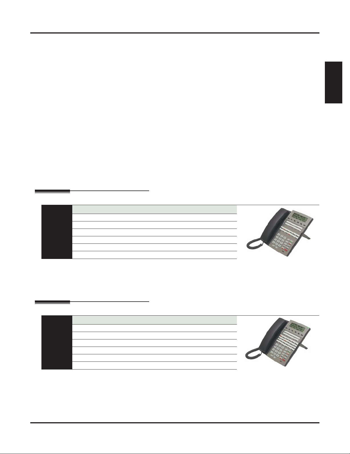
22-Button Display Telephone with Speakerphone
P/Ns 1090020 (Black) and 1090025 (White)
Display: 3 line x 24 character Speakerphone: Built-in, half-duplex
Soft Keys: 4 Wall Mount: Built-in
Feature Keys: 12 Angle Adjustment: 2 position built-in
Fixed Function Keys: 12 Backlit: No
At a Glance
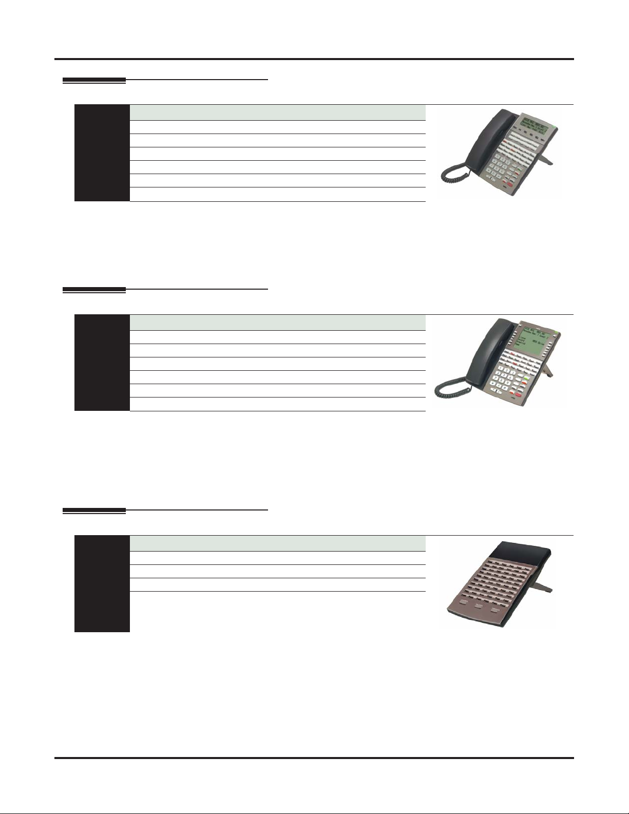
34-Button Backlit Display Telephone with Speakerphone
At a Glance
Speed Dial Bin Keys: 10 Dual LEDs: Yes
Headset jack: RJ-10 built-in (standard handset type)
The 22-Button Display Telephone features a large 3 line-by-24 character alphanumeric display with 4 Interactive Soft Keys for intuitive feature access. It also provides 10 Personal Speed Dial bin keys, 12 programmable
Feature Keys and 12 fixed function keys for streamlined operation. Additionally, this telephone offers a headset
jack and built-in speakerphone. Unique features include dual LEDs, a Ring/Message Lamp (to show ringing,
Caller ID, and voice mail messages), built-in wall mounting, and an innovative two position angle adjustment.
P/Ns 1090021 (Black) and 1090026 (White)
Display: 3 line x 24 character Speakerphone: Built-in, half-duplex
Soft Keys: 4 Wall Mount: Built-in
Feature Keys: 24 Angle Adjustment: 2 position built-in
Fixed Function Keys: 12 Backlit: Yes
Speed Dial Bin Keys: 10 Dual LEDs: Yes
Headset jack: RJ-10 built-in (standard handset type)
The 34-Button Display Telephone features a large 3 line-by-24 character backlit alphanumeric display with
4 Interactive Soft Keys for intuitive feature access. It also provides 10 Personal Speed Dial bin keys, 24 programmable Feature Keys and 12 fixed function keys for streamlined operation. Additionally, this telephone
offers a backlit keypad, a headset jack, and built-in speakerphone. Unique features include dual LEDs, a
Ring/Message Lamp (to show ringing, Caller ID, and voice mail messages), built-in wall mounting, and an
innovative two position angle adjustment.
DSX-40 Hardware Manual
Components ◆ 1
2 ◆
DSX Telephones
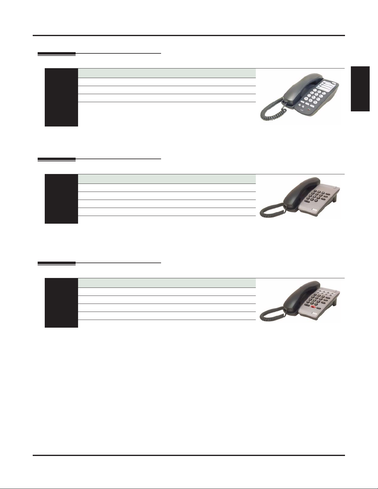
34-Button Backlit Display Telephone with Full-Duplex Speakerphone
P/Ns 1090022 (Black) and 1090027 (White)
Display: 3 line x 24 character Speakerphone: Built-in, full-duplex
Soft Keys: 4 Wall Mount: Built-in
Feature Keys: 24 Angle Adjustment: 2 position built-in
Fixed Function Keys: 12 Backlit: Yes
At a Glance
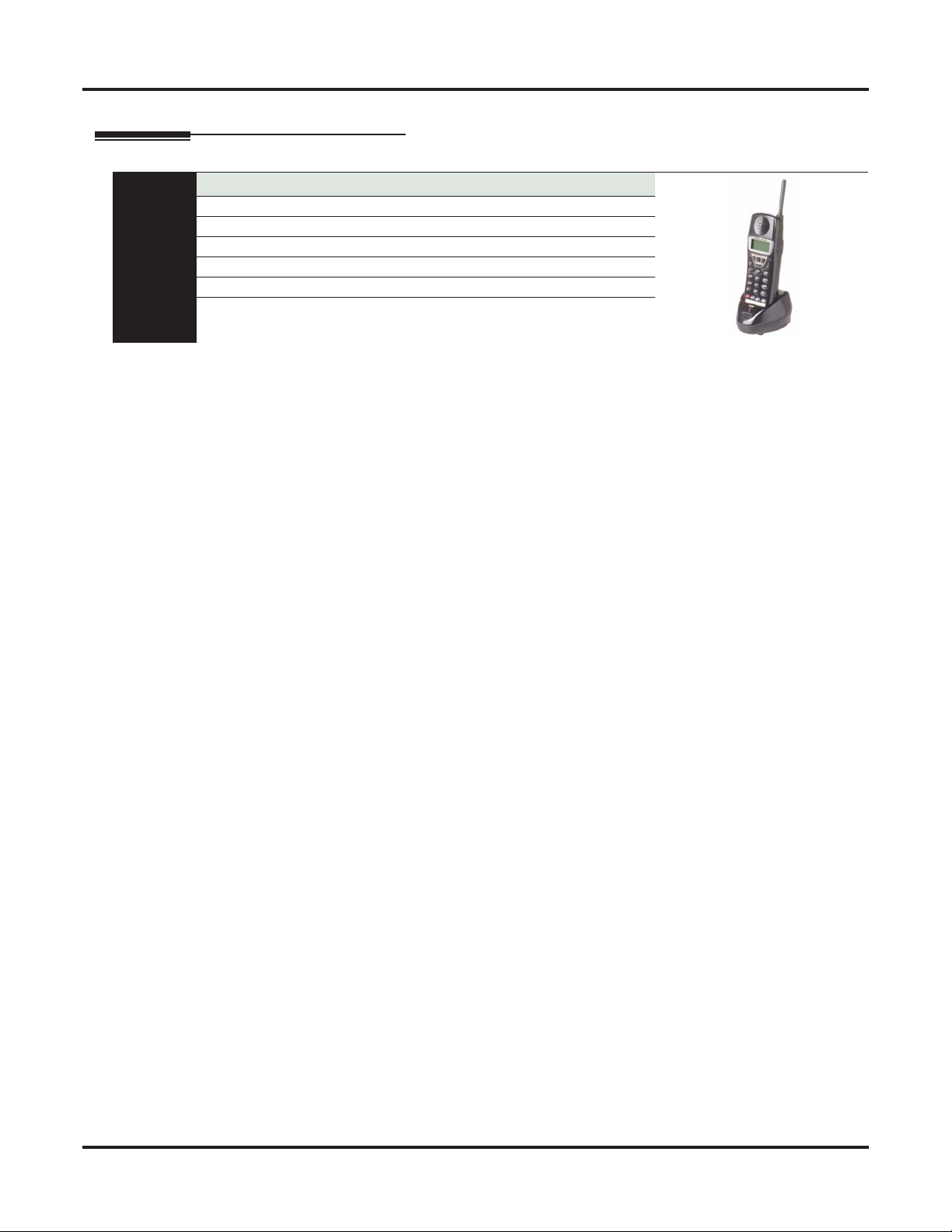
34-Button Backlit Super Display Telephone with Half-Duplex Speakerphone
Speed Dial Bin Keys: 10 Dual LEDs: Yes
Headset jack: RJ-10 built-in (standard handset type)
This feature-rich 34-Button Display Telephone features a large 3 line-by-24 character backlit alphanumeric display with 4 Interactive Soft Keys for intuitive feature access. It also provides 10 Personal Speed Dial bin keys,
24 programmable Feature Keys and 12 fixed function keys for streamlined operation. Additionally, this telephone offers a built-in full duplex speakerphone (with no external speaker or microphone required), a backlit
keypad, and a headset jack. Unique features include dual LEDs, a Ring/Message Lamp (to show ringing, Caller
ID, and voice mail messages), built-in wall mounting, and an innovative two position angle adjustment.
P/Ns 1090030 (Black) and 1090031 (White)
Display: 9 line x 24 character Speakerphone: Built-in, half-duplex
Soft Keys: 12 Wall Mount: Built-in
Feature Keys: 24 Angle Adjustment: 2 position built-in
Fixed Function Keys: 12 Backlit: Yes
At a Glance
Speed Dial Bin Keys: 10 Dual LEDs: Yes
Headset jack: RJ-10 built-in (standard handset type)
The Super Display Telephone is the system’s most sophisticated telephone instrument. It features a large 9
line-by-24 character backlit alphanumeric display with 12 Interactive Soft Keys for intuitive feature access.
It also provides 10 Personal Speed Dial bin keys, 24 programmable Feature Keys and 12 fixed function keys
for streamlined operation. Additionally, this telephone offers a built-in half duplex speakerphone (with no
external speaker or microphone required), a backlit keypad, and a headset jack. Unique features include dual
LEDs, a Ring/Message Lamp (to show ringing, Caller ID, and voice mail messages), built-in wall mounting,
and an innovative two position angle adjustment.
60-Button DSS Console
P/Ns 1090024 (Black) and 1090029 (White)
Feature Keys: 60 Wall Mount: Built-in
Fixed Function Keys: 3 Angle Adjustment: 2 position built-in
Dual LEDs: Yes
At a Glance
The 60-Button DSS Console provides a display keyset with a
button access to extensions, trunks, and selected system features. Enhanced by Answer, Release, and
Transfer fixed function keys, the 60-Button DSS Console is a great time saver for users that do a lot of call
processing (such as operators or dispatchers). By default, the DSS Console is set up with Hotline keys to
extensions and 14 feature keys for quick access to Page, Park and the system Night Mode
Note: DSX80/160 supports DS1000/2000 telephones if the system has a DSTU Card (P/N 80021A) installed.
Components
60-button Busy Lamp Field (BLF) and one-
DSX-40 Hardware Manual
Single Line Telephones
Single Line Telephones
DTH-1-1 Single Line Telephone
P/N 780034 (Black)
Fixed Function Keys: 5 Message Waiting: Yes
Speed Dial Bin Keys: 4 Ring/Message Waiting Lamp: Yes
Selectable Ring Tones: Yes Wall Mount: Built-in
At a Glance
The DTH-1-1 is a cost-effective analog single line telephone that offers 5 fixed feature keys, 4 Speed Dial
bin keys and Message Waiting. The built-in Message Waiting lamp will flash for incoming calls or when the
user has a message. To simplify working in groups, The DTH-1-1 provides 3 selectable ring tones.
DTR-1-1 Single Line Telephone
P/Ns 780020 (Black) and 780021 (White)
Fixed Function Keys: 5 Message Waiting: Yes
Speed Dial Bin Keys: None Ring/Message Waiting Lamp: No
Selectable Ring Tones: Yes Wall Mount: Built-in
At a Glance
Handsfree Monitor: No
The DTR-1-1 is a stylish yet rugged analog single line telephone with 5 fixed feature keys and Message
Waiting. Similar to the DTH-1-1, the DTR-1-1 has a built in Message Waiting lamp that will flash for incoming calls or when the user has a message. The DTR-1-1 offers programmable ring pitch and volume. Built-in
wall mounting and a bridged data jack for connecting a modem or answering machine are standard.
Components
DTR-1HM-1 Single Line Telephone
P/Ns 780025 (Black) and 780026 (White)
Fixed Function Keys: 7 Message Waiting: Yes
Speed Dial Bin Keys: 8 Ring/Message Waiting Lamp: Yes
Selectable Ring Tones: Yes Wall Mount: Built-in
At a Glance
Handsfree Monitor: Yes
The DTR-1HM-1 provides all the features of the DTR-1-1 in addition to two additional fixed function keys
(for Hold and Speaker/Monitor) and 8 Speed Dial bin keys. For convenient on-hook dialing and call monitor,
the DTR-1HM-1 also offers Handsfree Monitor.
DSX-40 Hardware Manual
Components ◆ 3
DSX Cordless Telephone
DSX Cordless Telephone
DSX Cordless Lite II
P/N 730087
Display: 2 line x 16 character Transmission: 900 MHz Narrow Band FM
Status Icons: 4 Range: 350 feet (site dependent)
Feature Keys: 4 Max Units Per Site: 30 (12 in close proximity)
Fixed Function Keys: 8 Battery Life: Up to 7 hours talk time
At a Glance
Channels: 30
The DSX Cordless Lite II Telephone (P/N 730087) is a 900 Mhz digital narrow band FM cordless telephone
that provides mobility, flexibility and convenience for those who spend much of the workday away from
their desk. Fully integrated with the DSX system, the DSX Cordless Lite II Telephone offers many standard
features such as Call Forwarding, Call Coverage, Hotline, and Voice Mail. Complemented by 4 fully programmable function keys (with LEDs), the DSX Cordless Lite II Telephone achieves a whole new level of
convenience and mobility. An easy-to-read 16-character by 2-line LCD display (with four status icons), volume controls, a rechargeable Nickel Metal Hydride Battery Pack, and a handy belt clip round out the elegant
and affordable DSX Cordless Lite II Telephone.
4 ◆
The Cordless II Lite Telephone includes the following:
• Base Unit
• Base Unit AC Adaptor (P/N 630618)
• Base Wall Mount Bracket (P/N 730608)
• Base Line Cord
• Handset
• Handset Charger (P/N 730632)
• Handset Charger AC Adaptor (P/N 730619)
• Handset Charger Wall Mount Bracket (P/N
730633)
• Handset Battery (P/N 730631)
• Belt Clip (P/N 730634)
Components
DSX-40 Hardware Manual
Headsets
Headsets
Corded Headsets for DSX Keysets and DTR/DTH SLTs
The following corded headsets are compatible with DSX keysets and the DTR/DTH single line telephones.
Check with your supplier for their latest offerings.
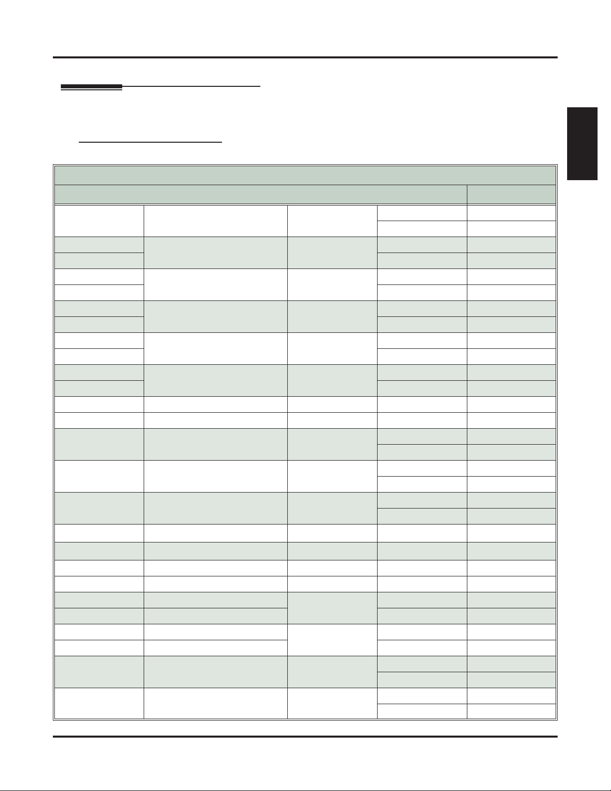
NEC / Plantronics Headsets
NEC / Plantronics Amplified Headsets
NEC P/N
Description Style Microphone Type
Voice Tube P31
- Polaris Starset In-the-Ear
Noise Canceling P31N
750631
Voice Tube P41
Polaris Mirage On-the-Ear
- Noise Canceling P41N
750632
Voice Tube P51
Polaris Supra Monaural Over-the-Head
750636 Noise Canceling P51N
-
Voice Tube P61
Polaris Supra Binaural Over-the-Head
750633 Noise Canceling P61N
750630
Voice Tube P81
Polaris TriStar In-the-Ear
- Noise Canceling P81N
750634
Voice Tube P91
Polaris Encore Monaural Over-the-Head
- Noise Canceling P91N
- Polaris Encore Binaural Over-the-Head Voice Tube P101
760635 Noise Canceling P101N
- Polaris DuoSet Convertible
Over-the-Head,
On-the-Ear
Voice Tube P141
Noise Canceling P141N
Voice Tube P151
- Polaris DuoPro On-the-Ear
Noise Canceling P151N
Voice Tube P161
- Polaris DuoPro Over-the-Head
Noise Canceling P161N
- Polaris DuoPro Convertible
- Polaris DuoPro Convertible
Over-the-Head,
Over-the-Head,
Voice Tube P171
Noise Canceling P171N
- Polaris DuoPro Behind-the-Head Voice Tube P181
- Polaris DuoPro Behind-the-Head Noise Canceling P181N
750643 Polaris/SupraPlus Monaural
Voice Tube P251
Over-the-Head
750644 Polaris/SupraPlus NC Monaural Noise Canceling P251N
- Polaris/SupraPlus NC Binaural
Voice Tube P261
Over-the-Head
750645 Polaris/SupraPlus NC Binaural Noise Canceling P261N
Voice Tube P351
- Polaris SupraPlus SL Monaural Over-the-Head
Noise Canceling P351N
Voice Tube P361
- Polaris SupraPlus SL Binaural Over-the-Head
Noise Canceling P361N
Plantronics Model
Components
Number
DSX-40 Hardware Manual
Components ◆ 5
Headsets
6 ◆
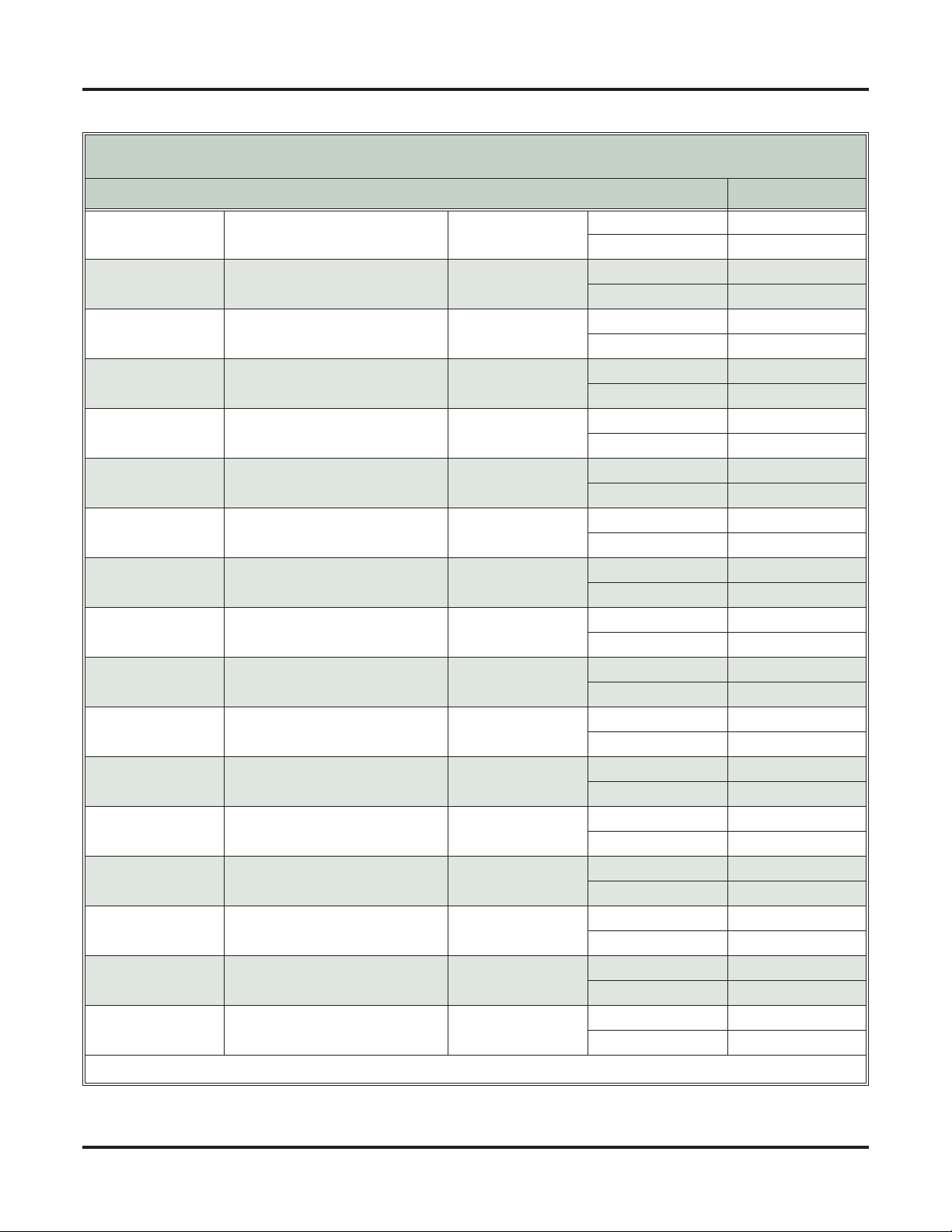
NEC P/N
NEC / Plantronics Non-Amplified Headsets
Description Style Microphone Type
(http://www.plantronics.com)
- Polaris StarSet In-the-Ear
- Polaris Mirage On-the-Ear
- Polaris Supra Monaural Over-the-Head
- Polaris Supra Binaural Over-the-Head
- Polaris TriStar In-the-Ear
- Polaris Encore Monaural Over-the-Head
- Polaris Encore Binaural Over-the-Head
- Polaris Freehand Monaural In-the-Ear
- Polaris DuoSet Convertible
- Polaris DuoPro On-the-Ear
- Polaris DuoPro Over-the-Head
- Polaris DuoPro Convertible
- Polaris DuoPro Behind-the-Head
- Polaris SupraPlus Monaural Over-the-Head
- Polaris SupraPlus Binaural Over-the-Head
- Polaris SupraPlus SL Monaural Over-the-Head
- Polaris SuproPlus SL Binaural Over-the-Head
1
Requires Vista M12 Amplifier and Handset/Headset Switch
Over-the-Head,
On-the-Ear
Over-the-Head,
On-the-Ear
1
Plantronics Model
Number
Voice Tube H31
Noise Canceling H31N
Voice Tube H41
Noise Canceling H41N
Voice Tube H51
Noise Canceling H51N
Voice Tube H61
Noise Canceling H61N
Voice Tube H81
Noise Canceling H81N
Voice Tube H91
Noise Canceling H91N
Voice Tube H101
Noise Canceling H101N
Voice Tube H131
Noise Canceling H131N
Voice Tube H141
Noise Canceling H141N
Voice Tube H151
H151N
Voice Tube H161
Noise Canceling H161N
Voice Tube H171
Noise Canceling H171N
Voice Tube H181
Noise Canceling H181N
Voice Tube H251
Noise Canceling H251N
Voice Tube H261
Noise Canceling H261N
Voice Tube H351
Noise Canceling H351N
Voice Tube H361
Noise Canceling H361N
Components
DSX-40 Hardware Manual
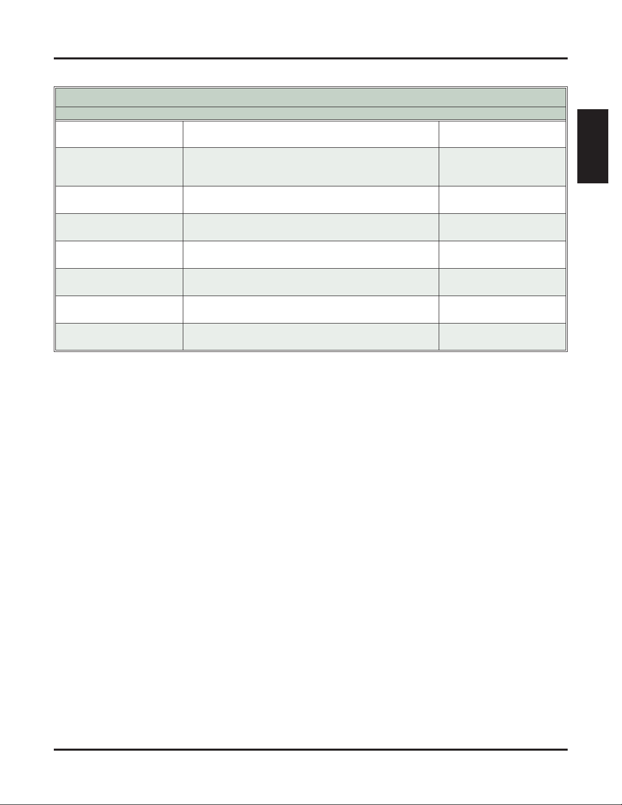
Accessories and Replacement Parts for Polaris Headsets
NEC P/N
750655
750657
750656
750 650
750651 Clear Voice Tube for Mirage and Supra Replacement (1)
750653
750652 Clear Voice Tube for Encore and Tristar (1)
750654 Rainbow Voice Tube for Encore and Tristar (Package of 6)
Polaris Extension Cable (10 ft.)
• For all Polaris headset models.
Clothing Clip Replacement (1)
• For all Polaris Mirage, Tristar, and Encore headset
models.
Ear Cushion (Package of 2)
• For Supra and Encore models.
Windscreen Replacement (1)
• For Supra NC headset models
Rainbow Voice Tube for Mirage and Supra Replacement
(Package of 6)
Description Plantronics Item Number
Headsets
40703-01
29961-01 or
29961-13
15729-11
24316-01 or
24316-04
17593-01 or
17593-06
17593-7 or
17593-80
29960-01 or
29960-13
29960-70 or
29960-80
Components
DSX-40 Hardware Manual
Components ◆ 7
Headsets
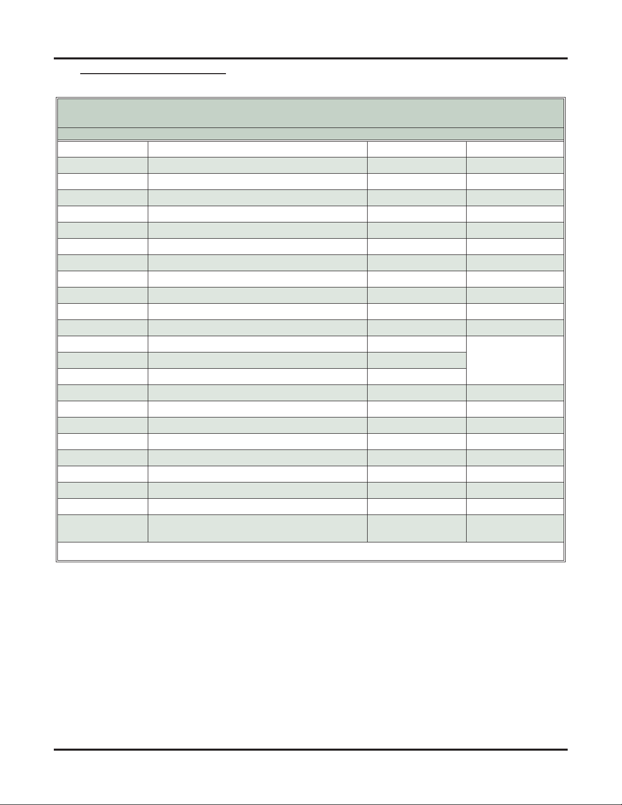
GN Netcom Headsets
8 ◆
GN Netcom Non-Amplified Headsets
(http://www.gnnetcom.com/us/en)
Model Number Description Microphone Type Style
1
GN 2110 STD01 2100 Sound Tube Monaural Sound-Tube Over-the-Head
GN 2120 NCD01 2100 Flex Monaural Noise-Canceling Over-the-Head
GN 2115 STD01 2100 SoundTube Binaural Sound-Tube Over-the-Head
GN 2125 NCD01 2100 Flex Binaural Noise-Canceling Over-the-Head
GN 2117 STD01 2100 SoundTube Monaural Sound-Tube On-the-Ear
GN 2127 NCD01 2100 Flex Monaural Noise-Canceling On-the-Ear
GN 2110 ST 2100 SoundTube Monaural Sound-Tube Over-the-Head
GN 2120 NC 2100 Flex Monaural Noise-Canceling Over-the-Head
GN 2115 ST 2100 SoundTube Binaural Sound-Tube Over-the-Head
GN 2125 NC 2100 Flex Binaural Noise-Canceling Over-the-Head
GN 2127 ST 2100 SoundTube Monaural Sound-Tube On-the-Ear
GN 2127 NC 2100 Flex Monaural Noise-Canceling On-the-Ear
405-SF Surefit Monaural Voice-Tube
405-FLEX-SF Surefit Monaural Noise-Canceling
405-UNC-SF Surefit Monaural Noise-canceling
3-Way Convertible:
Over-the-Head, Ear-
hook, Earloops
ADP-I ADDvantage Plus Monaural Noise-Canceling Over-the-Head
ADP-II ADDvantage Plus Binaural Noise-Canceling Over-the-Head
GN 2200 2200 Omega Monaural Noise-Canceling Over-the-Head
GN 2225 2200 Omega Binaural Noise-Canceling Over-the-Head
OG-I Orator-G Monaural Noise-Canceling Over-the-Head
OG-II Orator-G Binaural Noise-Canceling Over-the-Head
Contour LX-G Contour LX-G Monaural Noise-Canceling On-the-Ear
Stratus Ultra-G Stratus Ultra-G Monaural Noise-Canceling On-the-Ear
805-Flex 805-Flex Binaural Noise-Canceling
1
Requires GN8000 MPA Amplifier and Headset Switch.
Under-the-Chin or
Behind-the-Neck
Components
DSX-40 Hardware Manual
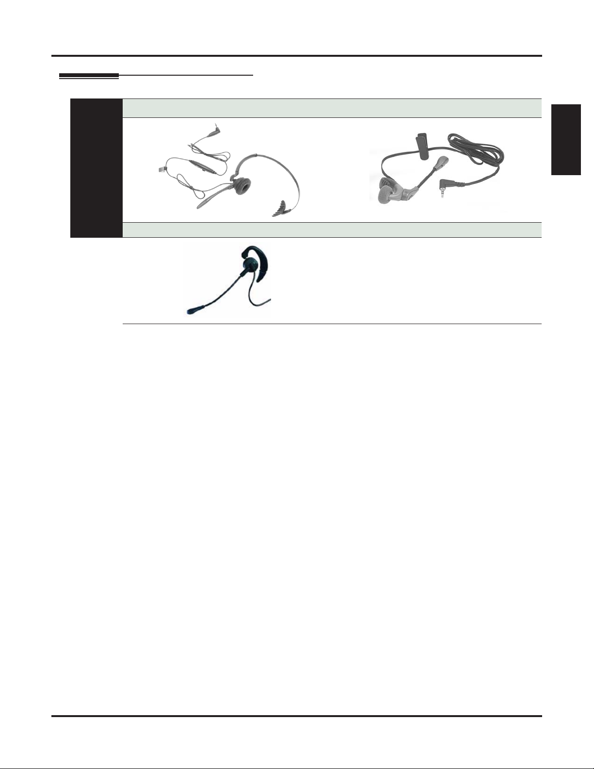
Headsets for DSX Cordless Lite II Telephone
P/N 750637 (M175) P/N 750642 (MX150)
At a Glance
P/N 730602 (EXP9530)
Headsets
Components
The following headsets are available for the DSX Cordless Lite II Telephone:
• M175 Headband Style (P/N 750637)
• MX150 Earloop Style (P/N 750642)
• EXP 9350 Convertible Headset (P/N 730602)
DSX-40 Hardware Manual Components ◆ 9
DESI Telephone Label System
DESI Telephone Label System
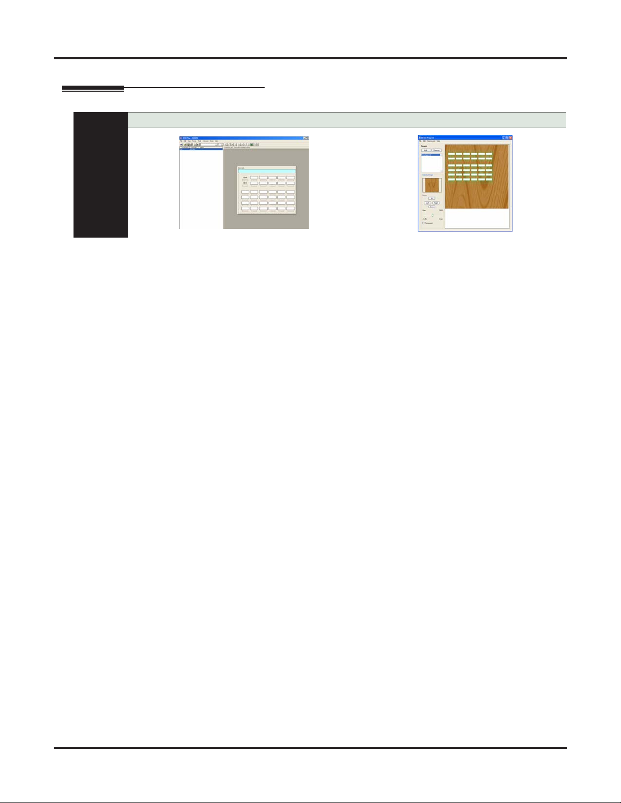
DESI Plus Labeling Software
At a Glance
DESI Plus Labeling Software is a Windows-compatible application for printing customized key data on specially designed DESI telephone labels. Use DESI Plus Labeling Software to create quick, professional custom labels that can be printed on virtually any office ink jet or laser printer. DESI Labeling Software
features:
• Automatic extension numbering
• Label templates that can be saved for later use
• Copy and paste functions
• Perforated and die cut labels for a perfect fit
• Choice of fonts and font colors
• Space for incorporating company logo
• User-printable background graphics (using DESI Preprint)
DESI Plus Labeling Software
DESI Plus Labeling Software is provided on the DSX System Document CD included with each DSX
telephone system.
10 ◆ Components DSX-40 Hardware Manual

DESI Telephone Labels
Labels for DSX Telephones Labels for NEC Single Line Telephones
At a Glance
The following DESI labels are available for DSX telephone “replacement” applications.
• 22-Button Display (pkg 20 with 10 backers)
- White (P/N 1093086)
- Black (P/N 1093085)
• 34-Button Display (pkg 20 with 10 backers)
- White (P/N 1093084)
- Black (P/N 1093083)
• 34-Button Super Display (pkg 20 with 10 backers)
- White (P/N 1093082)
- Black (P/N 1093081)
• 60-Button DSS Console (pkg 20 with 10 backers)
- White (P/N 1093080)
- Black (P/N 1093079)
DESI Telephone Label System
Components
The following DESI labels are available for DSX telephone “preprint” applications.
• 22-Button Display Preprint (pkg 25)
- P/N 1093072
• 34-Button Display Preprint (pkg 25)
- P/N 1093071
• 34-Button Super Display Preprint (pkg 25)
- P/N 1093070
• 60-Button DSS Console Preprint (pkg 25)
- P/N 1093069
The following DESI labels are available for the NEC analog single line telephones.
• For DTR-1-1
- Black (P/N 780400)
- Metallic green (P/N 780401)
- Metallic silver (P/N 780402)
- Lime green (P/N 780403)
- Preprint (blank) (P/N 780459)
• For DTR-1HM-1
- Black (P/N 780404)
- Metallic green (P/N 780405)
- Metallic silver (P/N 780406)
- Lime green (P/N 780407)
- Preprint (blank) (P/N 780460)
• For DTH-1-1
- Metallic silver (P/N 780450)
DSX-40 Hardware Manual Components ◆ 11
DSX-40 Common Equipment
DSX-40 Common Equipment
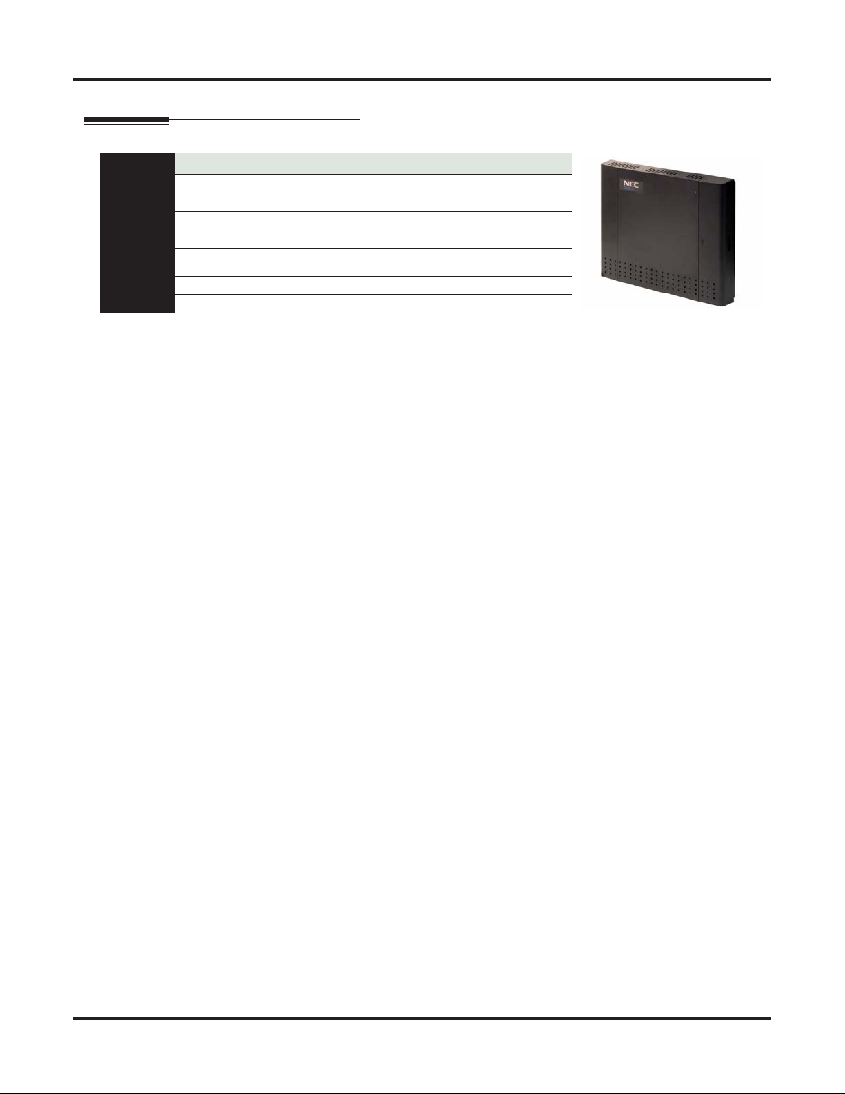
DSX-40 4x8x2 Key Telephone System with 2 Door Box Ports and Caller-ID
P/N 1090001
Digital extension ports:
Built-in: 8
Fully expanded: 24
Analog extension ports:
Built-in: 2
Fully expanded: 18
Built-in door box ports: 2
At a Glance
Built-in door box control relays: 2
Total Ports: 40 CompactFlash interface: Yes
Ethernet port: Yes (auto sensing) USB connector: Yes
DSX-40 is a compact, wall-mountable, more economical member of the DSX family that offers many of the
features and options of the larger DSX-80/160 in a smaller, self-contained cabinet. In its off-the-shelf basic
configuration, DSX-40 supports 4 CO (outside) lines with Caller ID, 8 DSX digital keyset extensions, and 2
analog (single line) extensions with power failure. Additionally, the basic DSX-40 provides:
• CompactFlash card interface (for IntraMail, software loading, and database backup)
• Conference circuits, DTMF receivers and DTMF generators
• NAND Flash for storing the system database
• Battery for short term (14 day) backup of the internal Real Time Clock and station parameters
• Two audio inputs for Background Music and Music on Hold (1/8” mono minijacks)
• One audio output for External Paging (1/8” mono minijack)
• Ethernet and USB ports for local and remote PC Programming
• RS-232 serial port for Station Message Detail Recording
• 2 DSX Analog Door Box ports with associated relays
• Built-in V.32BIS 14.4K BPS modem for remote maintenance
Analog line ports:
Built-in: 4
Total: 8
Expansion slots:
Station expansion slots: 2
Line expansion slots:1
Audio outputs: 1
Audio inputs: 2
Tips to remember:
1. The CPU also has a reset switch that provides the following three functions:
• System reset (when momentarily pressed).
• System initialization (when held down as power is turned on).
• Software update (when held down for a few seconds while a software update CompactFlash card is
installed).
2. DSX-40 provides FSK Message Waiting. It does not provide high voltage Message Waiting.
Even with all the value built into the basic off-the-shelf DSX-40, the system is easily expandable by adding
station and line PCBs. See DSX-40 PCBs (page 13) for more.
12 ◆ Components DSX-40 Hardware Manual
DSX-40 PCBs
DSX-40 PCBs
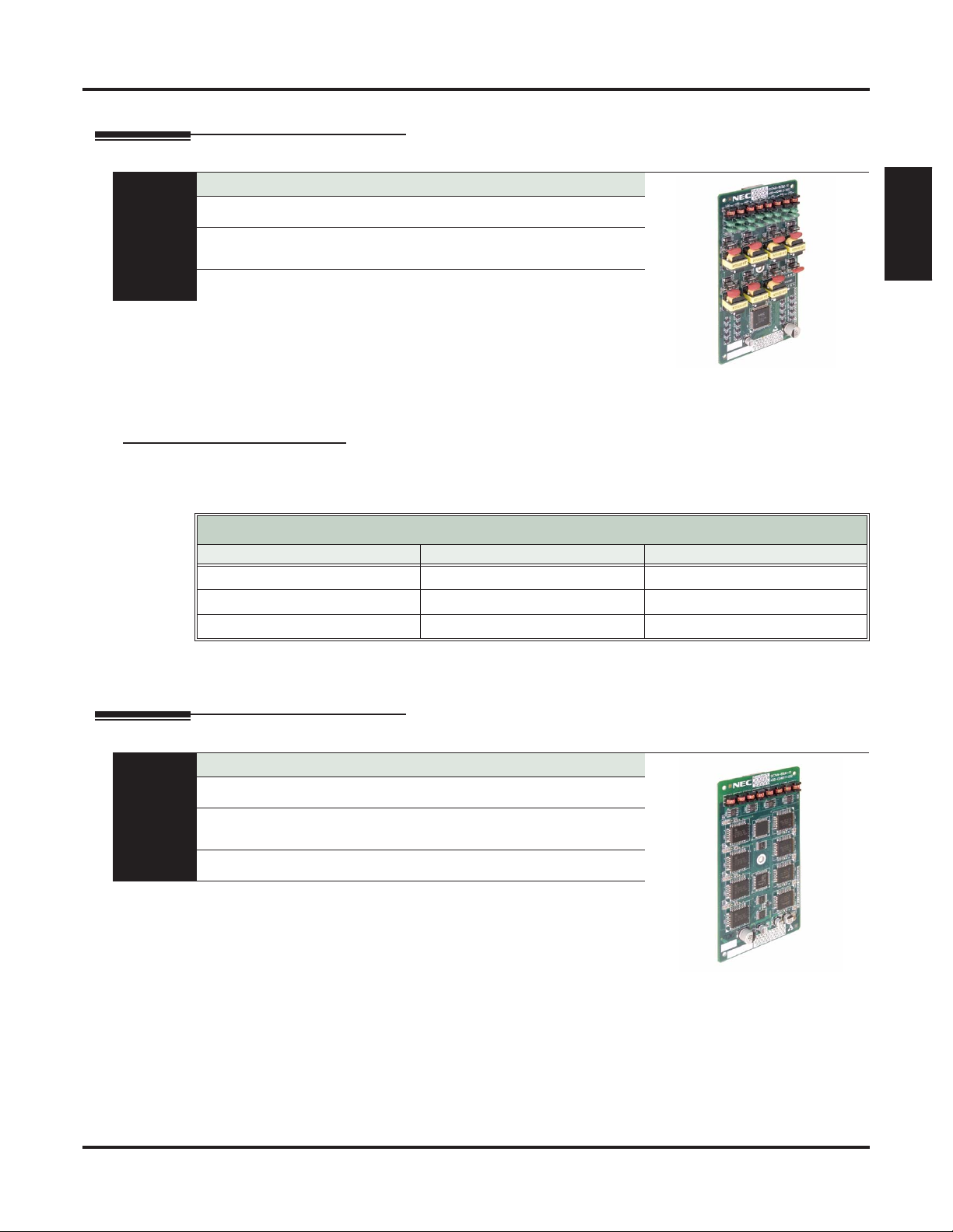
DSX-40 8-Port Digital Station (8ESIU) Card
P/N 1091002
Digital station ports: 8 Installs in either the top or middle DSX-40
Max. cards installed: 2 (16 additional digital station ports)
At a Glance
Max.digital ports: 24 (8 in each digital card
installed plus 8 built-in)
The 8-Port Digital Station Card is an expansion card that provides eight additional digital station ports. You
can install up to two 8-Port Digital Station Cards, using the upper and middle expansion slots, for a system
maximum of 24 digital stations.
Expansion Guidelines
The top 2 DSX-40 expansion positions are for the 8-port station cards, and you can install them in either
position in any combination.
Top Position (9-16) Middle Position (17-14) Total
8-Port Digital Card 8-Port Digital Card 24 Digital and 2 Analog
8-Port Digital Card 8-Port Analog Card 16 Digital and 10 Analog
8-Port Analog Card 8-Port Analog Card 8 Digital and 18 Analog
expansion slot.
Can be mixed with 8-Port Analog Station
Cards in any combination in the top and
middle expansion slots.
DSX-40 Station Card Capacities
Components
Tips to remember:
• The 8-Port Digital and 8-Port Analog Station Cards use the same expansion slots (upper and middle).
DSX-40 8-Port Analog Station (8SLIU) Card
P/N 1091003
Analog station ports: 8 Installs in either the top or middle DSX-40
Max. analog cards installed: 2 (16 additional analog station ports)
At a Glance
Max. analog ports: 18 (8 in each analog
card installed plus 2 built-in)
The 8-Port Analog Station Card is an expansion card that provides eight additional analog station ports. You
can install up to two 8-Port Analog Station Cards, using the upper and middle expansion slots, for a system
maximum of 18 analog stations.
Tips to remember:
• The 8-Port Digital and 8-Port Analog Station Cards use the same expansion slots (upper and middle).
expansion slot
Can be mixed with 8-Port Digital Station
Cards in any combination in the top and
middle expansion slots
DSX-40 Hardware Manual Components ◆ 13
DSX-40 PCBs
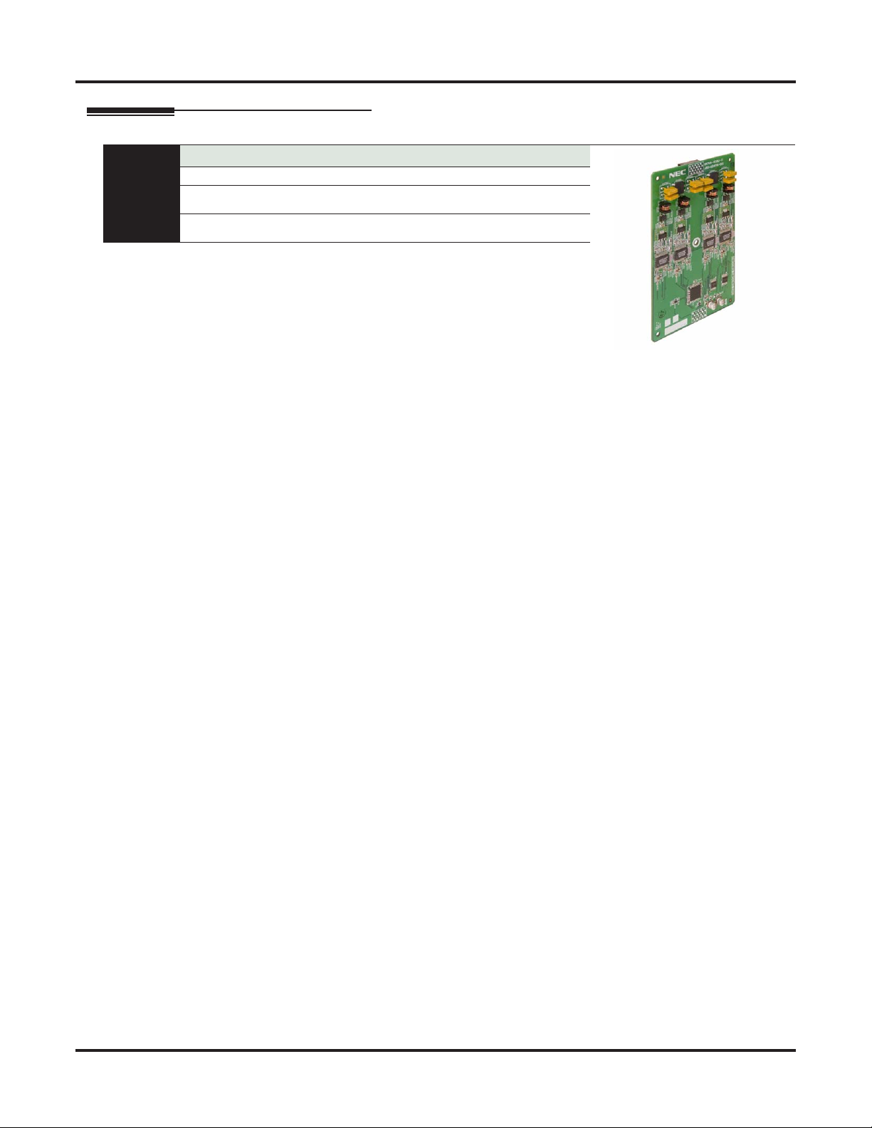
DSX-40 4 Port (4COIU) Line PCB with Caller ID
P/N 1091001
Line ports: 4 Installs only in the bottom expansion slot.
Max. line cards installed: 1 (4 additional
CO line ports)
At a Glance
Max. line ports: 8 (4 in the CO line card
plus 4 built-in)
The 4-Port CO Line Card with Caller ID is an expansion card that provides four additional CO line ports
with built-in Caller ID. You can install this card only in the bottom expansion slot for a system maximum of
8 outside line ports.
Tips to remember:
• You can install the 4-Port CO Line Card with Caller ID only in the bottom expansion slot.
Caller ID: Built in
Message Waiting: FSK only
14 ◆ Components DSX-40 Hardware Manual
IntraMail
IntraMail
DSX IntraMail 8 x 16
P/N 1091013
Ports: 8 Storage Hours: 16
Routing Mailboxes: 16
8 Announcement
8 Call Routing
Ring Group Mailboxes: 8 UCD Group Mailboxes: 8
At a Glance
Total Mailboxes:
DSX-40: 66
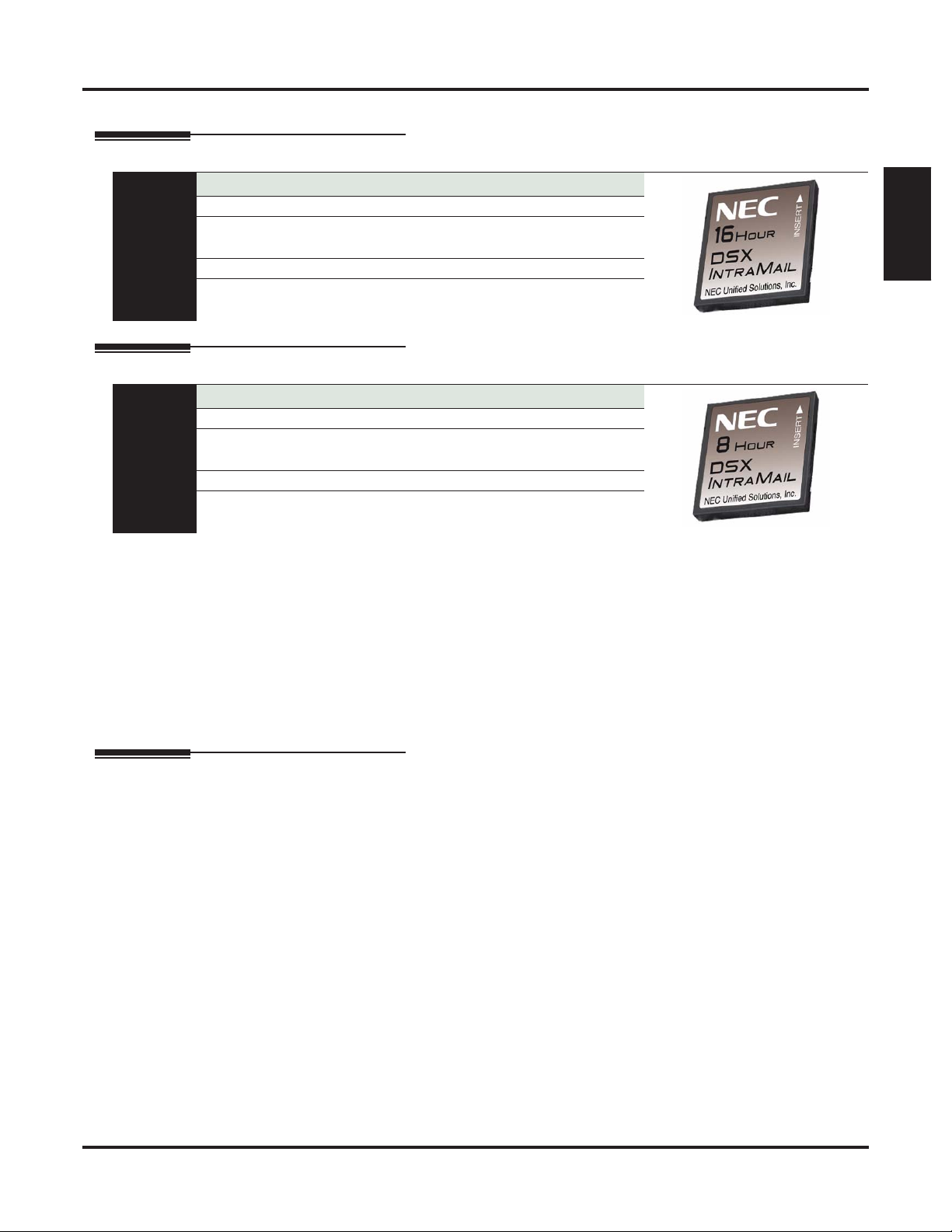
DSX IntraMail 4 x 8
P/N 1091011
Ports: 4 Storage Hours: 8
Routing Mailboxes: 16
8 Announcement
8 Call Routing
Ring Group Mailboxes: 8 UCD Group Mailboxes: 8
At a Glance
Total Mailboxes:
DSX-40: 66
IntraMail is a plug-in “in-skin” full-featured, DSP-based integrated Voice Mail with Automated Attendant
for DSX. It is available in two models:
• P/N 1091013 with 8 Voice Mail ports, 16 hours of message storage, and up to 160 mailboxes.
• P/N 1091011 with 4 Voice Mail ports, 8 hours of message storage, and up to 160 mailboxes.
Subscirber Mailboxes:
DSX-40: 34
Subscirber Mailboxes:
DSX-40: 34
Components
The IntraMail Automated Attendant answers incoming calls and routes them quickly and efficiently. Integrated
Voice Mail features include Conversation Record, Answering Machine Emulation, and Caller ID with Return
Call. Interactive Soft Keys guide the display telephone user through the extensive IntraMail feature set.
Tips to remember:
• After plugging in the IntraMail CompactFlash card, IntraMail automatically installs on power-up.
Built-In Automated Attendant
The Built-In Automated Attendant gives the system call answering and routing capabilities when IntraMail
is not installed. The Built-In Automated Attendant can use any of the first eight Call Routing Mailboxes
(001-008) for call handling, and each of these eight Routing Mailboxes can have a 30 second Instruction
Menu message (Attendant Greeting). The Routing Mailboxes must be Call Routing Mailboxes, and all other
Routing Mailbox types are ignored. Additionally, the Built-In Automated Attendant provides two voice mail
ports, allowing it to process two calls simultaneously.
The Built-In Automated Attendant does not provide voice mail.
Just like the full featured IntraMail Automated Attendant, the Built-In Automated Attendant can answer outside calls on each line according to the time of the day and day of the week that the call is ringing. After
answering, the Built-In Automated Attendant plays an Instruction Menu message (greeting) to the caller and
provides them with dialing options.
DSX-40 Hardware Manual Components ◆ 15
Miscellaneous Cards and Optional Equipment
Miscellaneous Cards and Optional Equipment
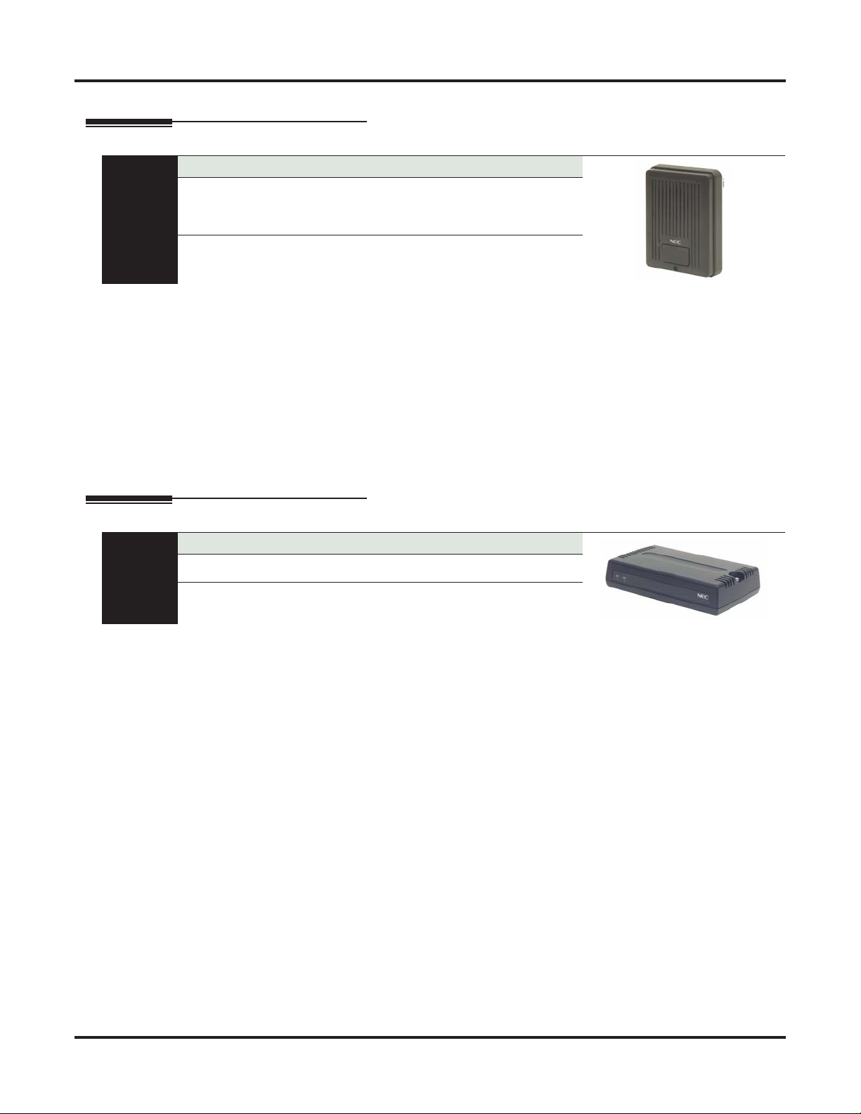
DSX Analog Door Box
P/N 922450
DSX-40:
• 2 built-in door box ports
• Additional door box ports requires 2PGDAD Modules connected to Digital Station
ports
•
At a Glance
The Analog Door Box is a self-contained Intercom unit typically used to monitor an entrance door. A visitor
at the door can press the Door Box call button (like a door bell). The Door Box then sends chime tones to all
extensions programmed to receive chimes. To answer the chime, the called extension user just lifts the handset. This lets the extension user talk to the visitor at the Door Box. The Door Box is convenient to have at a
delivery entrance, for example. It is not necessary to have company personnel monitor the delivery entrance;
they just answer the Door Box chimes instead.
Tips to remember:
• The Analog Door Box is a weather-tight unit and can be mounted outside.
• The maximum number of DSX Analog Door Boxes you can install is determined by the number of
2PGDAD Modules, which in turn is limited only by the availability of digital station ports.
• The DSX-40 has 2 built-in door box ports.
DSX 2PGDAD Module
P/N 0891027
Provides connection and relays for two
DSX Analog Door Boxes
At a Glance
The DSX 2PGDAD Module provides connection and relays for two DSX Analog Door Boxes. This module
connects to an available port on a DSX Digital Station (16ESIU) PCB.
Tips to remember:
• The maximum number of DSX Analog Door Boxes you can install is determined by the number of
2PGDAD Modules, which in turn is limited only by the availability of digital station ports.
Connects to digital station port
16 ◆ Components DSX-40 Hardware Manual

Miscellaneous Cards and Optional Equipment
DSX System Administrator (PC Program)
Free Download
Download the DSX System Administrator
from http://www.necdsx.com
At a Glance
The DSX System Administrator is a WindowsTM-based application you can use for programming
the telephone system and maintaining site databases, instead of using the conventional telephone
programming. The System Administrator provides:
● On-Line Programming (Direct Connection)
With the PC connected to the telephone system’s USB or Ethernet port, you can make immediate changes to the telephone system programming. While connected, the System Administrator also allows you to save your new data to a file on the PC hard disk, or upload a
“template” database from your PC to the system.
● Remote Programming
Using an IP or built-in modem connection between your PC and the remote system, you can
customize a customer’s system without leaving your office.
● Off-Line Programming
With Off-Line Programming, the PC Program allows you to set up a database on your PC off
line, connect to the telephone system, and upload the entire custom configuration.
● Database Save and Restore
Use the PC Program to save a site’s data to your PC hard disk. You can easily restore the saved
data later on, if required.
Components
DSX-40 Hardware Manual Components ◆ 17

Miscellaneous Cards and Optional Equipment
18 ◆ Components DSX-40 Hardware Manual

System Preparation
System Preparation
Unpacking
Unpack the equipment and check it against your equipment lists. Inspect for physical damage. If you are not
sure about a component’s function, review Components (page 1). Contact your Sales Representative if you
have additional questions.
Have the appropriate tools for the job on hand, including: a test set, a punch down tool and a digital voltmeter.
Before Installing
Make sure you have a building plan showing the location of the common equipment, extensions, the telco
demarcation and earth ground. In addition, the installation site must meet the requirements outlined in the
Standard Practices Manual.
Installation
Installation
Site Requirements
The common equipment is contained in the wall-mounted Main Equipment Cabinet. Choose a central location
for the cabinet that allows enough space for the equipment — and provides enough room for you to comfortably
work.
Figure 1: Installation Layout, DSX-40 (page 20)
requires.
and shows you about how much space your system
Single Line Telephone REN Limitations
Please note the following when installing single line telephones:
❥ The total Ringer Equivalence Number (REN) per system cannot exceed 10.
❥ The total REN per analog port cannot exceed 5.
❥ Ringer Equivalence is cumulative.
❥ A REN of 1 is the normal for an industry standard 2500 set with electromechanical ringer. Many phones
with electronic ringers have significantly lower RENs.
DSX-40 Hardware Manual Installation ◆ 19
Loading...