

Page 1

Manual Title
Additional Information
be certain.
100-231-445 C
MTS Criterion® Series 40
Product Information
Page 2

Copyright information © 2011 -2014 MTS Systems Corporation. All rights reserved.
Trademark information MTS and MTS Criterion are registered trademarks of MTS Systems Corporation
within the United States. These trademarks may be protected in other countries.
Proprietary information Software use and license is governed by MTS’ End User License Agreement
which defines all rights retained by MTS and granted to the End User. All
Software is proprietary, confidential, and owned by MTS Systems Corporation
and cannot be copied, reproduced, disassembled, decompiled, reverse
engineered, or distributed without express written consent of MTS.
Software validation and
verification
Publication information
MTS software is developed using established quality practices in accordance
with the requirements detailed in the ISO 9001 standards. Because MTSauthored software is delivered in binary format, it is not user accessible. This
software will not change over time. Many releases are written to be backwards
compatible, creating another form of verification.
The status and validity of MTS’ operating software is also checked during
system verification and routine calibration of MTS hardware. These controlled
calibration processes compare the final test results after statistical analysis
against the predicted response of the calibration standards. With these established
methods, MTS assures its customers that MTS products meet MTS’ exacting
quality standards when initially installed and will continue to perform as intended
over time.
MANUAL PART NUMBER PUBLICATION DATE
100-231-445 A January 2011
100-231-445 B March 2012
100-231-445 C June 2014
2
MTS Criterion® Series 40 Product Manual
Page 3

Contents
Technical Support 7
How to Get Technical Support 7
Before You Contact MTS Service Representative 7
If You Contact MTS by Phone 8
Preface 11
Before You Begin 11
Conventions 12
Documentation Conventions 12
Safety 13
General Safety Practices 13
Safety Practices Before System Operation 14
Safety Practices While the System Is in Operation 17
Hazard Labels 18
Introduction 21
About This Manual 21
Inappropriate Use 21
Description 22
Frame Controller 22
Software 22
Load Frame Components 24
Specifications 35
Common Specifications 36
Model Specifications 37
Dimensions 45
Installation 55
Frame Location and Ventilation 56
Leveling the Load Frame 57
MTS Criterion® Series 40 Product Manual
Contents
3
Page 4

Leveling the Table-Top Load Frame 57
Leveling the Floor-Standing Load Frame 58
Installing Optional Enclosures 59
Single-Column Load Frame 59
Dual-Column Load Frames 64
Controller Connections 69
Connecting the Main Power 69
Installing Cables 70
Accessory Mounting Dimensions 82
Model C41 Accessory Mounting Dimensions 83
Model C42 Accessory Mounting Dimensions 84
Model C43 Accessory Mounting Dimensions 86
Model C44 Accessory Mounting Dimensions 89
Model C45.504W Accessory Mounting Dimensions 91
Model C45.504/C45.105 Accessory Mounting Dimensions 93
Model C45.305 Accessory Mounting Dimensions 96
Model C45.605Accessory Mounting Dimensions 98
Operation 101
Main Power Switch (I/O) and Emergency-Stop 103
Setting Crosshead Travel Limits 105
Crush Zone Hazards 107
Fixture Mounting 108
Load Cell Mounting 109
Handset Control 114
Maintenance 117
Routine Maintenance Overview Checklist 117
Other service 119
Troubleshooting 121
Decommissioning 123
Appendix 125
Additional Digital I/O Information 125
Contents
4
MTS Criterion® Series 40 Product Manual
Page 5

Electromechanical Load Unit Maintenance and Service Logs 127
8 Hours/Daily 128
40 Hours/Weekly 129
2000 Hours 130
PC Maintenance and System Inspection 130
2000 Hours 131
System Checks 131
2000 Hours 132
Lubrication 132
2000 Hours 133
Frame and Work Area 133
Declaration of Conformity 135
MTS Criterion® Series 40 Product Manual
Contents
5
Page 6

Page 7

Technical Support
How to Get Technical Support
How to Get Technical Support
Start with your
manuals
Technical support
methods
The manuals supplied by MTS provide most of the information you need to use
and maintain your equipment. If your equipment includes software, look for
online help and README files that contain additional product inform ation.
If you cannot find answers to your technical questions from these sources, you
can use the Internet, e-mail, telephone, or fax to contact MTS for assistance.
MTS provides a full range of support services after your system is installed. If
you have any questions about a system or product, contact Technical Support in
one of the following ways.
Outside the U.S. For technical support outside the United States, contact your local sales and
service office. For a list of worldwide sales and service locations and contact
information, use the Global MTS link at the MTS web site:
www.mts.com > About MTS Systems > Global Presence (choose your
region in the right-hand column) > (choose the location closest to you)
Before You Contact MTS Service Representative
MTS can help you more efficiently if you have the following information
available when you contact us for support.
Know your contact
number and system
number
The contact number contains your company number and identifies your
equipment type (such as material testing or simulation). The number is typically
written on a label on your equipment before the system leaves MTS. If you do
not know your MTS contact number, contact your sales engineer.
When you have more than one MTS system, the system model number and series
number identifies your system. You can find your these number in your order
paperwork or directly on your equipment.
Identify the problem Describe the problem and know the answers to the following questions:
• How long and how often has the problem occurred?
• Can you reproduce the problem?
• Were any hardware or software changes made to the system before the
problem started?
• What are the equipment model numbers?
• What is the controller model (if applicable)?
• What is the system configuration?
MTS Criterion® Series 40 Product Manual
Technical Support
7
Page 8

If You Contact MTS by Phone
Know relevant
computer information
Know relevant
software information
For a computer problem, have the following information available:
• Manufacturer’s name and model number
• Operating software type and service patch information
• Amount of system memory
• Amount of free space on the hard drive where the application resides
• Current status of hard-drive fragmentation
• Connection status to a corporate network
For software application problems, have the following information available:
• The software application’s name, version number, build number, and (if
available) software patch number. This information can typically be found
in the About selection in the Help menu.
• The names of other applications on your computer, such as:
– Anti-virus software
– Screen savers
– Keyboard enhancers
– Print spoolers
– Messaging applications
If You Contact MTS by Phone
A Call Center agent registers your call before connecting you with a technical
support specialist. The agent asks you for your:
• Contact number
• Name
• Company name
• Company address
• Phone number where you can be reached
If your issue has a notification number, please provide that number. A new issue
will be assigned a unique notification number.
Technical Support
8
MTS Criterion® Series 40 Product Manual
Page 9

If You Contact MTS by Phone
Identify system type To enable the Call Center agent to connect you with the most qualified technical
support specialist available, identify your system as one of the following types:
• Electromechanical material test system
• Hydromechanical material test system
• Vehicle test system
• Vehicle component test system
• Aero test system
Be prepared to
troubleshoot
Write down relevant
information
After you call MTS logs and tracks all calls to ensure that you receive assistance for your
Prepare to perform troubleshooting while on the phone:
• Call from a telephone close to the system so that you can implement
suggestions made over the phone.
• Have the original operating and application software media available.
• If you are not familiar with all aspects of the equipment operation, have an
experienced user nearby to assist you.
In case Technical Support must call you:
• Verify the notification number.
• Record the name of the person who helped you.
• Write down any specific instructions.
problem or request. If you have questions about the status of your problem or
have additional information to report, please contact Technical Support again and
provide your original notification number.
MTS Criterion® Series 40 Product Manual
Technical Support
9
Page 10

Page 11

Before You Begin
Preface
Before You Begin
Safety first! Before you use your MTS product or system, read and understand the Safety
manual and any other safety information provided with your system. Improper
installation, operation, or maintenance can result in hazardous conditions that can
cause severe personal injury or death, or damage to your equipment and
specimen. Again, read and understand the safety information provided with your
system before you continue. It is very important that you remain aware of
hazards that apply to your system.
Other MTS manuals In addition to this manual, you may receive additional manuals in paper or
electronic form.
Manuals located on the product information CD will contain information that
pertains to your test system, such as:
• Hydraulic and/or mechanical accessory manuals
• Assembly drawings
• Parts lists
• Operation instructions
• Preventive maintenance tasks
Controller and application software manuals are typically included on the
software CD distribution disc(s).
MTS Criterion® Series 40 Product Manual
Preface
11
Page 12

Conventions
DANGER
WARNING
CAUTION
Conventions
Documentation Conventions
The following paragraphs describe some of the conventions that are used in your
MTS manuals.
Hazard conventions Hazard notices may be embedded in this manual. These notices contain safety
information that is specific to the activity to be performed. Hazard notices
immediately precede the step or procedure that may lead to an associated hazard.
Read all hazard notices carefully and follow all directions and recommendations.
Three different levels of hazard notices may appear in your manuals. Following
are examples of all three levels.
Note Refer to “Safety” on page 13 for general safety information.
Danger notices indicate the presence of a hazard with a high level of risk which,
if ignored, will result in death, severe personal injury, or substantial property
damage.
Warning notices indicate the presence of a hazard with a medium level of risk
which, if ignored, can result in death, severe personal injury, or substantial
property damage.
Caution notices indicate the presence of a hazard with a low level of risk which,
if ignored, could cause moderate or minor personal injury or equipment damage,
or could endanger test integrity.
Notes Notes provide additional information about operating your system or highlight
easily overlooked items. For example:
Note Resources that are put back on the hardware lists show up at the end of
the list.
Special terms The first occurrence of special terms is shown in italics.
Illustrations Illustrations appear in this manual to clarify text. They are examples only and do
not necessarily represent your actual system configuration, test application, or
software.
Electronic manual
conventions
This manual is available as an electronic document in the Portable Document
File (PDF) format. It can be viewed on any computer that has Adobe Acrobat
Reader installed.
12
Hypertext links The electronic document has many hypertext links displayed in a blue font. All
blue words in the body text, along with all contents entries and index page
numbers, are hypertext links. When you click a hypertext link, the application
jumps to the corresponding topic.
Preface
MTS Criterion® Series 40 Product Manual
Page 13

Safety
General Safety Practices
This section provides information about safety issues that pertain to
electromechanical systems in general. These issues include statements to the
intended use and foreseeable misuse of the system, the hazard zone, definition for
the graphical hazard labeling that is affixed to your product, and other (more
general) safety information that relates to the high-performance characteristics of
MTS Criterion electromechanical systems.
MTS Criterion test systems are designed to generate motions and forces and
impart these motions and forces into a test specimen.
When you prepare to operate the system and during system operation, ensure the
following:
• Do not use or allow personnel to operate the system who are not
General Safety Practices
experienced, trained, or educated in the inherent dangers associated with
high-performance electromechanical machines and who are not
experienced, trained, or educated with regard to the intended operation as it
applies to this test system.
• Do not disable safety components or features (including limit detectors,
light curtains, or proximity switches/detectors).
• Do not attempt to operate the system without appropriate personal safety
gear (for example, hearing, hand, and eye protection).
• Do not use specimens that are combustible, flammable, pressurized, or
explosive.
• Whenever possible, use tongs or similar device to handle specimens during
specimen installation.
• Do not use humans as specimens or allow humans to ride in or on the test
specimen or the test system for any purpose unless the system is man-rated
and all associated safety conditions are strictly enforced.
• Do not modify the system or replace system components using parts that are
not MTS component parts or effect repairs using parts or components that
are not manufactured to MTS specifications.
• Do not operate the system in an explosive atmosphere.
• Do not use the system in a test area where uncontrolled access to the test
system is allowed when the system is in operation.
If you have system related responsibilities (that is, if you are an operator, service
engineer, or maintenance person), you should study safety information carefully
before you attempt to perform any test system procedure.
MTS Criterion® Series 40 Product Manual
Safety
13
Page 14

Safety Practices Before System Operation
You should receive training on this system or a similar system to ensure a
thorough knowledge of your equipment and the safety issues that are associated
with its use. In addition, you should gain an understanding of system functions
by studying the other manuals supplied with your test system. Contact MTS for
information about the content and dates of training classes that are offered.
It is very important that you study the following safety information to ensure that
your facility procedures and the system’s operating environment do not
contribute to or result in a hazardous situation. Remember, you cannot eliminate
all the hazards associated with this system, so you must learn and remain aware
of the hazards that apply to your system at all times. Use these safety guidelines
to help learn and identify hazards so that you can establish appropriate training
and operating procedures and acquire appropriate safety equipment (such as
gloves, goggles, and hearing protection).
Each test system operates within a unique environment which includes the
following known variables:
• Facility variables (facility variables include the structure, atmosphere, and
utilities)
• Unauthorized customer modifications to the equipment
• Operator experience and specialization
• Test specimens
Because of these variables (and the possibility of others), your system can
operate under unforeseen circumstances that can result in an operating
environment with unknown hazards.
Improper installation, operation, or maintenance of your system can result in
hazardous conditions that can cause death, personal injury, or damage to the
equipment or to the specimen. Common sense and a thorough knowledge of the
system’s operating capabilities can help to determine an appropriate and safe
approach to its operation.
Safety Practices Before System Operation
Before you apply power to the test system, review and complete all of the safety
practices that are applicable to your system. The goal, by doing this, is to
improve the safety awareness of all personnel involved with the system and to
maintain, through visual inspections, the integrity of specific system
components.
Read all manuals Study the contents of this manual and the other manuals provided with your
system before attempting to perform any system function for the first time.
Procedures that seem relatively simple or intuitively obvious can require a
complete understanding of system operation to avoid unsafe or dangerous
situations.
Locate and read hazard
placards/labels
Safety
14
Find, read, and follow the hazard placard instructions located on the equipment.
These placards are placed strategically on the equipment to call attention to areas
such as known crush points and electrical voltage hazards.
MTS Criterion® Series 40 Product Manual
Page 15

Safety Practices Before System Operation
Locate lockout/tagout
points
Know facility safe
procedures
Locate Emergency Stop
buttons
Know where the lockout/tagout point is for all of the supply energies associated
with your system. This includes the hydraulic, pneumatic, electric, and water
supplies (as appropriate) for your system to ensure that the system is isolated
from these energies when required.
Most facilities have internal procedures and rules regarding safe practices within
the facility. Be aware of these safe practices and incorporate them into your daily
operation of the system.
Know the location of all the system Emergency Stop buttons so that you can
stop the system quickly in an emergency . Ensure that an Emergency Stop button
is located within 2 meters (6 feet) of the operator at all times.
Know controls Before you operate the system for the first time, make a trial run through the
operating procedures with the power off. Locate all hardware and software
controls and know what their functions are and what adjustments they require. If
any control function or operating adjustment is not clear, review the applicable
information until you understand it thoroughly.
Have first aid available Accidents can happen even when you are careful. Arrange your operator
schedules so that a properly trained person is always close by to render first aid.
In addition, ensure that local emergency contact information is posted clearly and
in sight of the system operator.
Know potential crush
and pinch points
Be aware of potential crush and pinch points on your system and keep personnel
and equipment clear of these areas.
Know electrical hazards When the system electrical power is turned on, minimize the potential for
electrical shock hazards. Wear clothing and use tools that are properly insulated
for electrical work. Avoid contact with exposed wiring or switch contacts.
Whenever possible, turn off electrical power when you work on or in proximity
to any electrical system component. Observe the same precautions as those given
for any other high-voltage machinery.
Keep bystanders safely
away
Keep bystanders at a safe distance from all equipment. Never allow bystanders to
touch specimens or equipment while the test is running.
Wear proper clothing Do not wear neckties, shop aprons, loose clothing or jewelry, or long hair that
could get caught in equipment and result in an injury. Remove loose clothing or
jewelry and restrain long hair.
Remove flammable
fluids from test specimen
Check bolt ratings and
torques
Remove flammable fluids from their containers or from components before you
install the container or component in a test system. If desired, you can replace the
flammable fluid with a non-flammable fluid to maintain the proper proportion of
weight and balance.
To ensure a reliable product, fasteners (such as bolts and tie rods) used in MTS
manufactured systems are torqued to specific requirements. Over torquing or
under torquing a fastener can create a hazardous situation due to the high forces
and pressures present in MTS test systems.
MTS Criterion® Series 40 Product Manual
Safety
15
Page 16

Safety Practices Before System Operation
On rare occasions, a fastener can fail even when it is correctly installed. Failure
usually occurs during torquing, but it can occur several days later. Failure of a
fastener can result in a high velocity projectile. Therefore, it is a good practice to
avoid stationing personnel in line with or below assemblies that contain large or
long fasteners.
Practice good
housekeeping
Protect hoses and
cables
Keep the floors in the work area clean. Do not leave tools, fixtures, or other items
not specific to the test, lying about on the floor, system, or decking.
Protect electrical cables from excessive temperatures that can cause the cables to
harden and eventually fail. Ensure that all cables have appropriate strain relief
devices installed at the cable and near the connector plug. Do not use the
connector plug as a strain relief.
Protect all system hoses and cables from sharp or abrasive objects that can cause
the hose or cable to fail. Never walk on hoses or cables or move heavy objects
over them. Consider system layout and route hoses and cables away from areas
that expose them to possible damage.
When removing hydraulic hoses for equipment repair or changing testing
components (for example, hydraulic grips), make sure to cap the hose ends to
avoid spilling hydraulic fluid.
Record changes If you change any operating procedure, write the change and the date of the
change in the appropriate manual.
Provide test area guards Use protective guards such as cages, enclosures, and special laboratory layouts
when you work with hazardous test specimens (for example, brittle or
fragmenting materials or materials that are internally pressurized).
Do not disable safety
devices
Your system might hav e active or passiv e safety devices instal led to prevent
system operation if the device indicates an unsafe condition. Do not disable such
devices as it can result in unexpected system motion.
Use appropriately sized
fuses
Provide adequate
lighting
Provide means to
access out-of-reach
components
Ensure equipment is
secure
Perodically run
consistancy checks
Safety
16
Whenever you replace fuses for the system or supply, ensure that you use a fuse
that is appropriately sized and correctly installed. Undersized or oversized fuses
can result in cables that overheat and fuses that explode. Either instance creates a
fire hazard.
Ensure adequate lighting to minimize the chance of operation errors, equipment
damage, and personal injury. You need to see what you are doing.
Make sure you can access system components that might be out of reach while
standing on the floor. For example, ladders or scaffolding might be required to
reach load cell connectors on tall load units.
Make sure the equipment is secure or provide vibration isolation. Some testing
can be performed at resonant frequencies that might cause the equipment to
vibrate and move during testing.
Pressing the Emergency-Stop button causes the system to automatically run a
consistency check. The Emergency-Stop button should be pressed occasionally
to run the constancy check.
MTS Criterion® Series 40 Product Manual
Page 17

Safety Practices While the System Is in Operation
Safety Practices While the System Is in Operation
Wear appropriate
personal protection
Wear eye protection when you work with electromechanical testing machines,
breakable specimens, or when anything characteristic to the specimen could
break apart.
W ear ear protection when you work near electric motors, pumps, or other devices
that generate high noise levels. Some systems can create sound pressure levels
that exceed 70 dbA during operation.
W ear appropriate personal protection equipment (gloves, boots, suits, respirators)
whenever you work with fluids, chemicals, or powders that can irritate or harm
the skin, respiratory system, or eyes.
Provide test area guards Use protective guards such as cages, enclosures, and special laboratory layouts
when you work with hazardous test specimens (for example, brittle or
fragmenting materials or materials that are internally pressurized).
Expect specimen
temperature changes
During cyclic testing, the specimen temperature can become hot enough to cause
burns. Wear personal protection equipment (gloves) when handling specimens.
Handle chemicals safely Whenever you use or handle chemicals (for example, cleaning fluids, hydraulic
fluid, batteries, contaminated parts, electrical fluids, and maintenance waste),
refer to the appropriate MSDS documentation for that material and determine the
appropriate measures and equipment required to handle and use the chemical
safely. Ensure that the chemical is disposed of appropriately.
Know system interlocks Interlock devices should always be used and properly adjusted. Interlock devices
are designed to minimize the chance of accidental damage to the test specimen or
the equipment. Test all interlock devices for proper operation immediately before
a test. Do not disable or bypass any interlock devices as doing so could allow
crosshead movement regardless of the true interlock condition.
Know system limits Never rely on system limits, such as mechanical limits or software limits, to
protect you or any personnel. System limits are designed to minimize the chance
of accidental damage to test specimens or to equipment. T est all limits for proper
operation immediately before a test. Always use these limits and adjust them
properly.
Do not disturb sensors Do not bump, wiggle, adjust, disconnect, or otherwise disturb a sensor (such as
an accelerometer or extensometer) or its connecting cable when power is applied.
Ensure secure cables Do not change any cable connections when electrical power is applie d. If you
attempt to change a cable connection while the system is in operation, an open
control loop condition can result. An open control loop condition can cause a
rapid, unexpected system response which can result in severe personal injury,
death, or damage to equipment. Also, ensure that all cables are connected after
you make any changes in the system configuration.
Stay alert Avoid long periods of work without adequate rest. In addition, avoid long periods
of repetitious, unvarying, or monotonous work because these conditions can
contribute to accidents and hazardous situations. If you are too familiar with the
work environment, it is easy to overlook potential hazards that exist in that
environment.
MTS Criterion® Series 40 Product Manual
Safety
17
Page 18
Hazard Labels
Stay clear of moving
equipment/avoid crush
points
Know the causes of
unexpected crosshead
motions
Do not use RF
transmitters
Hazard Labels
Stay clear of mechanical linkages, connecting cables, and hoses that move
because you can get pinched, crushed, tangled, or dragged along with the
equipment. High forces generated by the system can pinch, cut, or crush anything
in the path of the equipment and cause serious injury. Stay clear of any potential
crush points. Most test systems can produce sudden, high-force motion. Never
assume that your reactions are fast enough to allow you to escape injury when a
system fails.
The high force and velocity capabilities of MTS systems can be destructive and
dangerous (especially if crosshead motion is unexpected). The most likely causes
of unexpected crosshead response are operator error and equipment failure due to
damage or abuse (such as broken, cut, or crushed cables and hoses; shorted wires;
overstressed feedback devices; and damaged components within the control
loop). Eliminate any condition that could cause unexpected crosshead motion.
Keep radio frequency (RF) transmitters away from the workstation computers,
remote terminals, and electronics consoles. Intense RF fields can cause erratic
operation of the more sensitive circuits in the system.
The following hazard labels and icons are located on the test frame.
L
ABEL DESCRIPTION
Lift the machine upright.
Moving parts present.
Moving parts can crush and cut.
Keep hands away from moving parts.
18
Safety
MTS Criterion® Series 40 Product Manual
Page 19
LABEL DESCRIPTION
Flying objects.
Danger of eye injury.
Wear safety glasses.
Tip over hazard.
Use outriggers when machine is standalone.
Do not start, operate, or service machine
until you read and understand the operator’s
manual.
Hazard Labels
Failure to do so could result in serious injury.
There are no customer-serviceable parts on
the MTS
To turn the pulley, manually move the
crosshead upward and downward.
Pulleys can be turned by hand when power is
disabled.
Criterion electromechanical frames.
WEEE The Waste Electrical and Electronic Equipment (WEEE) symbol ( ) means
that the controller and its electronic parts must not be disposed of as unsorted
municipal waste. Proper disposal is required by approved electronic waste
collection agencies. Customers in the EC region who desire to return an end-oflife controller and its electronic parts are encouraged to contact your local MTS
Systems Sales/Service Offices for instructions.
MTS Criterion® Series 40 Product Manual
Safety
19
Page 20

Page 21

Introduction
About This Manual
Purpose The purpose of this manual is to help you understand your testing system, its
Inappropriate Use
Contents Description 22
About This Manual
capabilities, and operating requirements. This manual provides information for
all MTS Criterion Series 40 Material Test system, from the lowest force model (1
kN), to the highest (600 kN). Read each section carefully and refer to the manual
whenever you need assistance.
Before you attempt to use the MTS Criterion Series 40 Material Test System,
read and understand this manual. Improper installation or operation of this
product can result in hazardous conditions that can cause severe personal injury
or death, and damage your equipment and specimen.
Load Frame Components 24
Specifications 35
MTS Criterion® Series 40 Product Manual
Introduction
21
Page 22

Description
Description
Every MTS Criterion Series 40 Material Test System is comprised of a load
frame, electronic frame controller, and testing software.
The load frame has a rectangular shape and includes a base unit and one or two
vertical columns. The two-column models have a fixed upper transverse beam.
The moving crosshead is driven by precision ball screws on the load frame. The
crosshead is coupled to the ball screw(s) with high-strength, precision ball nuts
and rides on the ball bearings. This configuration is very efficient in minimizing
friction and wear. The ball screws are preloaded. This feature removes the
backlash so that position can be measured with increased accuracy over nonpreloaded ball screws.
The load frame drive is located in the frame base. The drive motor is connected
to the lower end of the ball screws by a series of belts and drive pulleys. On the
two-column machines, motor rotation causes synchronous rotation of the ball
screws, which causes the crosshead to move up or down. On the single-column
machines, motor rotation causes the rotation of the single ball screw, which
causes the crosshead to move up or down.
Frame Controller
Software
The frame controller is responsible for the following:
• Provides main data and signal processing power.
• Detects the activation of limit switches.
• Provides the interface between the software (computer) and the frame.
• Provides digital servocontrol for speed and position accuracy.
• Automatically identifies accessories, including load cells and
extensometers, with the self-identify feature.
• Communicates with the handset.
• Provides programmable data acquisition rate (up to 1000 Hz maximum).
• Commands the motor.
MTS testing software has various method templates available. The method
templates in the General T esting Package provide a starting point in configuring
test methods that conform to your testing needs. The General Testing Package is
separated into four specific testing categories:
22
Introduction
• MTS Tensile
• MTS Compression
• MTS Flex
• MTS Peel-Tear
MTS Criterion® Series 40 Product Manual
Page 23

Software
Many additional features can be purchased to meet your company’s specific
needs. Some of these features might already be part of the system you ordered, or
they can be added to your system as your requirements change. Refer to the
testing software manual for additional information.
MTS Criterion® Series 40 Product Manual
Introduction
23
Page 24
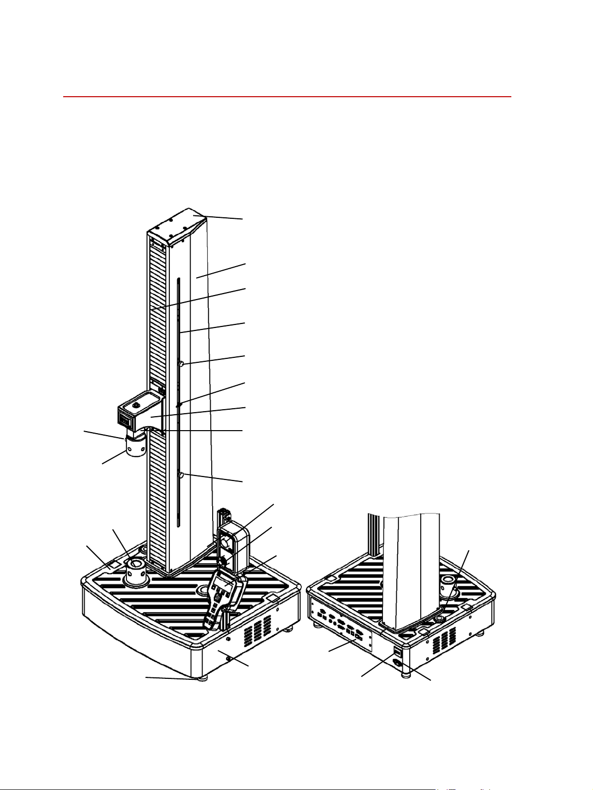
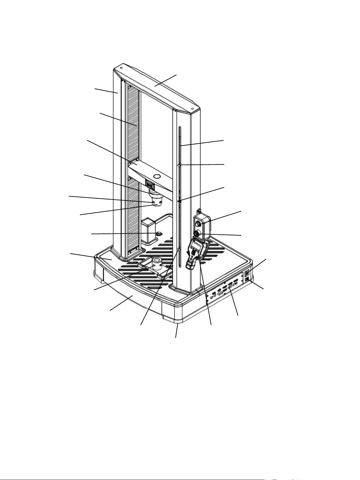
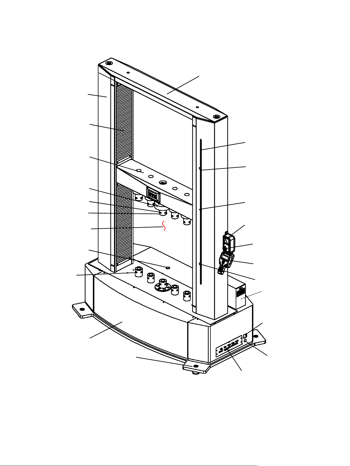
Load Frame Components
Limit Rod
Upper Limit Stop
Limit Switch Actuator
Lower Limit Stop
System-Enabled Light
Power Switch
Power Cord
Controller
Handset
Leveling Foot
Emergency Stop
Base
Base Adapter
Mat
Adapter
Pin
Load Cell
(inside)
Crosshead
Ball Screw Cover
Top Beam
Column Cover
Manual Unload
Load Frame Components
The following figures show the various components for the single-column and
two-column load frames. To familiarize yourself with the various components of
your frame, refer to the figure that shows your model number.
For dimensions, see the specification tables in the “Specifications” on page 35.
24
Introduction
Model C41.103 - Rated Force Capacity 1 kN
MTS Criterion® Series 40 Product Manual
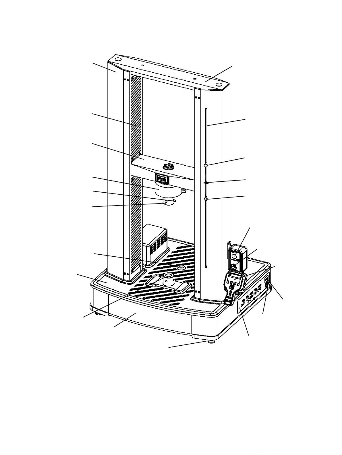
Page 25
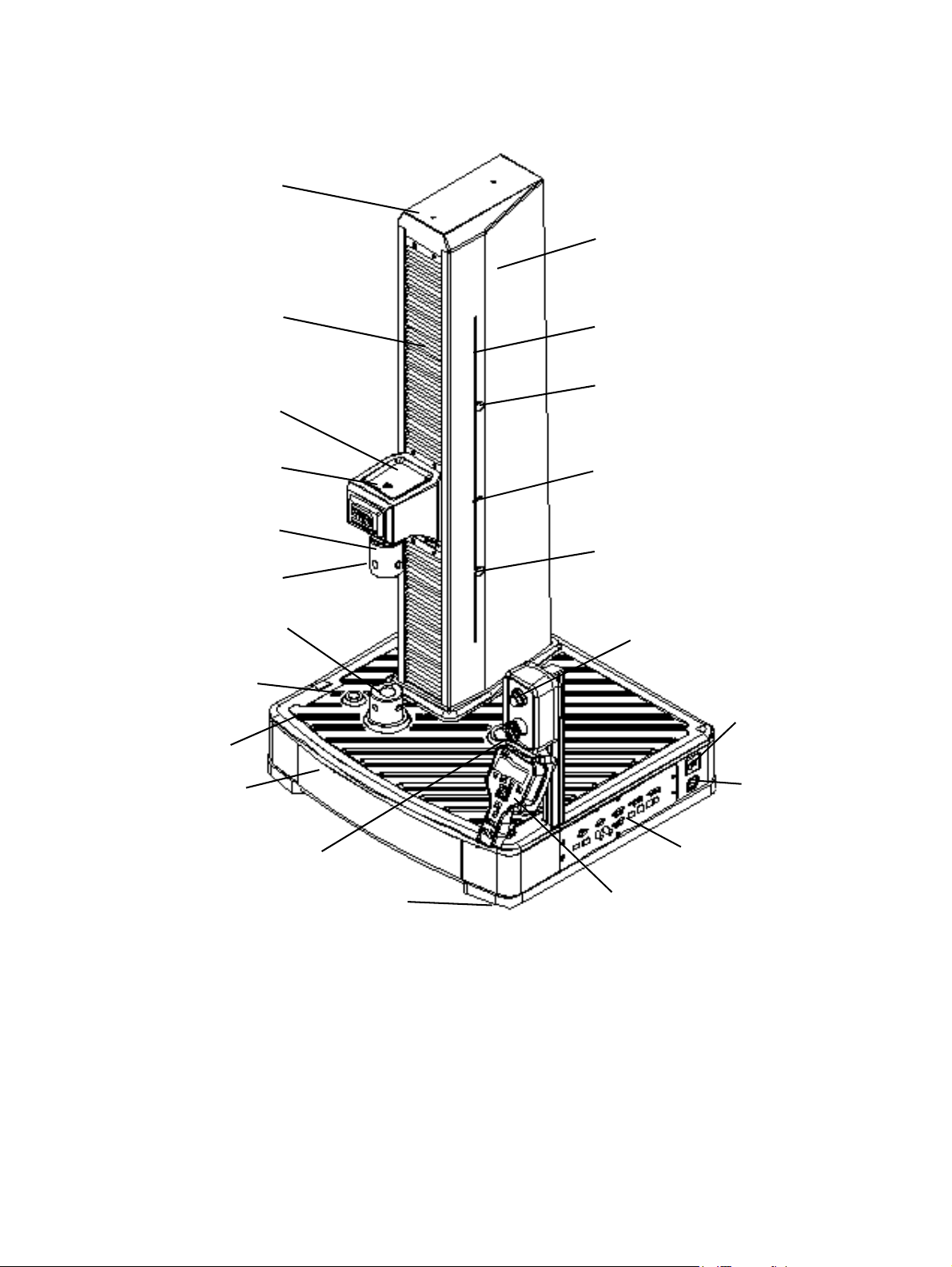
Limit Rod
Upper Limit Stop
Limit Switch Actuator
Lower Limit Stop
System-Enabled Light
Power Switch
Power Cord
Controller
Handset
Leveling Foot
Emergency Stop
Base
Base Adapter
Mat
Adapter
Pin
Load Cell
(inside)
Crosshead
Ball Screw Cover
Top Beam
Column Cover
Manual Unload
Load Frame Components
Model C42.503 - Rated Force Capacity 5 kN
MTS Criterion® Series 40 Product Manual
Introduction
25
Page 26
Load Frame Components
Top Beam
Ball Screw Cover
Load Cell
Pin
Adapter
Mat
Base Adapter
Base
Crosshead
Leveling Foot
Lower Limit Stop
Controller
Power Cord
Power Switch
Handset
Emergency Stop
System-Enabled Light
Limit Switch Actuator
Upper Limit Stop
Limit Rod
Column Cover
Manual Unload
Model C43.104 - Rated Force Capacity 10 kN
26
Introduction
MTS Criterion® Series 40 Product Manual
Page 27
Load Frame Components
Top Beam
Ball Screw Cover
Load Cell
Pin
Adapter
Mat
Base Adapter
Base
Crosshead
Leveling Foot
Lower Limit Stop
Controller
Power Cord
Power Switch
Handset
Emergency Stop
System-Enabled Light
Limit Switch Actuator
Upper Limit Stop
Limit Rod
Column Cover
Manual Unload
Model C43.304 and C43.504 - Rated Force Capacity 30 kN, 50 kN
MTS Criterion® Series 40 Product Manual
Introduction
27
Page 28
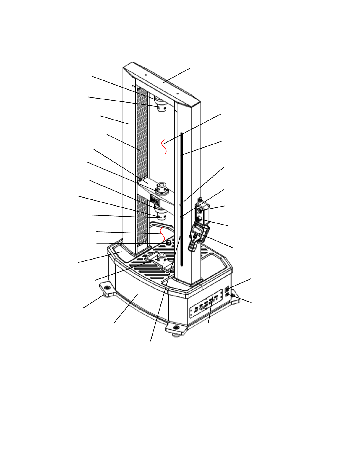
Load Frame Components
TopBeam
Ballscrewcover
Top Beam
Load Cell
Adapter
Ball Screw Cover
Crosshead
Adapter
Load Cell
Pin
Adapter
Mat
Base Adapter
Leveling Foot
Base
Lower Limit Stop
Handset
Controller
Power Cord
Power Switch
Emergency Stop
System-Enabled Light
Upper Limit Stop
Limit Switch Actuator
Limit Rod
Upper Test Space
Lower Test Space
Column Cover
Manual Unload
Model C44.104 and C44.304 - Rated Force Capacity 10 kN, 30 kN
28
Introduction
MTS Criterion® Series 40 Product Manual
Page 29
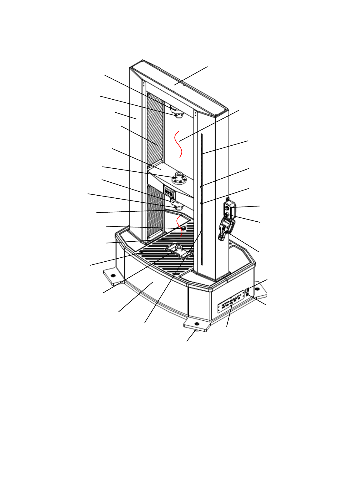
Top Beam
Load Cell
Adapter
Ball Screw Cover
Crosshead
Load Cell
Pin
Adapter
Mat
Leveling Foot
Lower Limit Stop
Handset
Controller
Power Cord
Power Switch
Upper Limit Stop
Limit Switch Actuator
Limit Rod
Base
Base Adapter
Emergency Stop
Adapter
System-Enabled Light
Upper Test Space
Manual Unload
Column Cover
Lower Test Space
Load Frame Components
Model C45.504 and C45.105 - Rated Force Capacity 50 kN, 100 kN
MTS Criterion® Series 40 Product Manual
Introduction
29
Page 30
Load Frame Components
Top Beam
Ball Screw Cover
Crosshead
Load Cell
Pin
Adapter
Leveling Foot
Lower Limit Stop
Handset
Controller
Power Cord
Power Switch
Upper Limit Stop
Limit Switch Actuator
Limit Rod
Base
Manual Unload
Emergency Stop
System-Enabled Light
Lower Test Space
Column Cover
Base Adapter
NI Signal
Acquisition Box
Model C45.504W - Rated Force Capacity 50 kN
30
Introduction
MTS Criterion® Series 40 Product Manual
Page 31

Top Beam
Ball Screw Cover
Crosshead
Load Cell
Pin
Adapter
Mat
Leveling Foot
Lower Limit Stop
Handset
Controller
Power Switch
Upper Limit Stop
Limit Switch Actuator
Limit Rod
Base
Base Adapter
Emergency Stop
System-Enabled Light
Column Cover
Manual Unload
Load Frame Components
Model C45.305 (Front)- Rated Force Capacity 300 kN
MTS Criterion® Series 40 Product Manual
Introduction
31
Page 32

Load Frame Components
Power Cord
AC Main Power Switch
and Circuit Breaker
32
Introduction
Model C45.305 (Back)- Rated Force Capacity 300 kN
MTS Criterion® Series 40 Product Manual
Page 33

Load Frame Components
Top Beam
Ball Screw Cover
Crosshead
Load Cell
Pin
Adapter
Leveling Foot
Lower Limit Stop
Handset
Controller
Power Switch
Upper Limit Stop
Limit Switch Actuator
Limit Rod
Base
Base Adapter
Emergency Stop
System-Enabled Light
Column Cover
Model C45.605 (Front)- Rated Force Capacity 600 kN
MTS Criterion® Series 40 Product Manual
Introduction
33
Page 34

Load Frame Components
Power Cord
AC Main Power Switch
and Circuit Breaker
Manual Unload
34
Introduction
Model C45.605 (Back)- Rated Force Capacity 600 kN
MTS Criterion® Series 40 Product Manual
Page 35

Specifications
Specifications
This section provides specifications for MTS Criterion Electromechanical
Material Testing System frames and accessory mounting dimensions.
Note Specifications are subject to change without notice. Contact MTS for
verification of critical specifications.
MTS Criterion® Series 40 Product Manual
Introduction
35
Page 36

Specifications
Common Specifications
The following specifications are for all MTS Criterion frames. Specifications for
the specific models are located in the following tables.
ALIBRATION STANDARD ISO 7500 CLASS 0.5 OR ASTM E4 ISO 7500 CLASS 1
C
Force range 1-100% of rated force capacity 0.5-1% of force rated
capacity
Rated force capacity at max test speed 100%
Maximum test speed at rated force
capacity
Force indicating accuracy ± 0.5 % of indicating
Speed accuracy
Position accuracy Within ± 0.5%
Strain accuracy ASTM E83 or ISO 8513
Security protection Over-Force, travel limits, over-voltage and others
Over force protection 10%
Data acquisition rate
Control loop rate
Environmental requirements
Operating temperature
Operating humidity
Storage temperature
100%
Set speed < 0.01 mm/min: speed accuracy is within ± 1.0% of set
speed
Set speed ≥ 0.01 mm/min: speed accuracy is within ± 0.2% of set
speed
1000 Hz
1000 Hz
For indoor use only
5-40°C (41-104°F)
5-85% Noncondensing
-18-49°C (0-120°F)
Maximum storage humidity
Maximum altitude
Motor and drive system
Ball screws
Position measurement Encoder
Additional DC conditioning channels 2 channels
Additional incremental encoder
conditioning channels
Introduction
36
90% Noncondensing
2000 m (6562 ft)
AC Servomotor
Preloaded
1 channel
MTS Criterion® Series 40 Product Manual
Page 37

Specifications
Model Specifications
Specifications of Model C41
P
ARAMETER SPECIFICATION
MODEL C41.103
Maximum rated force capacity 1 kN (220 lbf)
Force capacity options 1 N, 5 N, 10 N, 25 N, 50 N, 100 N, 250 N, 500 N, 1 kN
(0.2 lbf, 1 lbf, 2 lbf, 5 lbf, 10 lbf, 20 lbf, 50 lbf, 110 lbf,
220 lbf)
Frame type 1 Guide column, table-top
Test zone Single
Maximum test speed
Minimum test speed 0.005 mm/min (0.0002 in/min)
Position resolution 0.000051 mm (0.000002 in)
Vertical test space
Standard length 1100 mm (43.31 in)
Crosshead travel
Standard length 900 mm (35.4 in)
Clearance from loading axis to column cover 100 mm (3.94 in)
Frame height
Standard length 1520 mm (59.84 in)
Frame width 560 mm (22.05 in)
Frame depth 530 mm (20.87 in)
Weight
Standard length with enclosure
Standard length without enclosure
Power requirements 200-230 V AC
3000
mm/min (118 in/min)
80 kg (176 lb)
60 kg (132 lb)
5 Amp.
50/60 Hz
1000 W
1 Phase
MTS Criterion® Series 40 Product Manual
Introduction
37
Page 38

Specifications
Specifications of Model C42
P
ARAMETER SPECIFICATION
MODEL C42.503
Maximum rated force capacity 5 kN (1100 lbf )
Force capacity op tions 1 N, 5 N, 10 N, 25 N, 50 N, 100 N, 250 N, 500 N
1 kN, 2 kN, 5 kN
(0.2 lbf, 1 lbf, 2 lbf, 5 lbf, 10 lbf, 20 lbf, 50 lbf, 110 lbf
220 lbf, 450 lbf, 1100 lbf)
Frame type 1 Guide column, table-top
Test zone Single
Maximum test speed
Minimum test speed 0.005 mm/min (0.0002 in/min)
Position resolution 0.00005 mm (0.000002 in)
Vertical test space
Standard length
Extended length
Crosshead travel
Standard length
Extended length
Clearance from loading axis to column cover 100 mm (3.94 in)
Frame height
Standard length
Extended length
Frame width 704 mm (27.7 in)
Frame depth 636 mm (25 in)
Weight
2000
mm/min (78.7 in/min)
820 mm (32.3 in)
1120 mm (44.1 in)
650 mm (25.6 in)
950 mm (37.4 in)
1332 mm (52.44 in)
1632 mm (64.25 in)
Standard length with enclosure
Standard length without enclosure
Extended length with enclosure
Extended length without enclosure
Power requirements 200-230 V AC
Introduction
38
142 kg (312 lb)
112 kg (246 lb)
161 kg (354.2 lb)
125 kg (275 lb)
5 Amp
50/60 Hz
1000 W
1 Phase
MTS Criterion® Series 40 Product Manual
Page 39

Specifications of Model C43 (part 1 of 2)
P
ARAMETER SPECIFICATION
MODEL C43.104 C43.304 C43.504
Maximum rated force capacity 10 kN 30 kN 50 kN
Specifications
Force capacity options 100 N, 250 N, 500
N,1 kN, 2.5 kN, 5
kN, 10 kN
(20 lbf, 50 lbf, 110
lbf, 220 lbf, 500 lbf,
1100 lbf, 2200 lbf)
Frame type 2 Guide columns
Table-top
Test zone Single Single Single
Maximum test speed 2000 mm/min
(78.7 in/min)
Minimum test speed 0.005 mm/min
(0.0002 in/min)
Position resolution 0.00005 mm
(0.000002 in)
Vertical test space
Standard length
Extended length
1200 mm (47.2 in)
1500 mm (59.1 in)
100 N, 250 N, 500
N,1 kN, 2.5 kN, 5 kN,
10 kN, 20 kN, 30 kN
(20 lbf, 50 lbf, 110 lbf,
220 lbf, 500 lbf, 1100
lbf, 2200 lbf, 4400 lbf,
6600 lbf)
2 Guide columns
Table-top
1020 mm/min
(40.16 in/min)
0.005 mm/min
(0.0002 in/min)
0.00006 mm
(0.0000024 in)
1200 mm (47.2 in)
1500 mm (59.1 in)
100 N, 250 N, 500
N,1 kN, 2.5 kN, 5 kN,
10 kN, 20 kN, 30 kN,
50 kN
(20 lbf, 50 lbf, 110 lbf,
220 lbf, 500 lbf, 1100
lbf, 2200 lbf, 4400 lbf,
6600 lbf, 11000lbf)
2 Guide columns
Table-top
750 mm/min
(29.53 in/min)
0.005 mm/min
(0.0002 in/min)
0.00006 mm
(0.0000024 in)
1200 mm (47.2 in)
1500 mm (59.1 in)
Crosshead travel
Standard length
Extended length
Space between columns 425 mm (16.73 in) 420 mm (16.54 in) 420 mm (16.54 in)
Frame height
Standard length
Extended length
Frame width 794 mm (31.26 in) 826 mm (32.52 in) 826 mm (32.52 in)
Frame depth 757 mm (29.8 in) 768 mm (30.24 in) 768 mm (30.24 in)
1000 mm (39.37 in)
1300 mm (51.18 in)
1616 mm (63.6 in)
1916 mm (75.43 in)
1000 mm (39.37 in)
1300 mm (51.18 in)
1752 mm (68.97 in)
2052 mm (80.28 in)
1000 mm (39.37 in)
1300 mm (51.18 in)
1752 mm (68.97 in)
2052 mm (80.28 in)
MTS Criterion® Series 40 Product Manual
Introduction
39
Page 40

Specifications
Weight
Specifications of Model C43 (part 2 of 2)
Standard length wi th en closure
Standard length without
enclosure
Extended length with enclosure
Extended length without
enclosure
Power requirement s 200-230 V AC
212 kg (466.4 lb)
175 kg (385 lb)
232 kg (510.4 lb)
190 kg (418 lb)
10 Amp
50/60 Hz
2000 W
1 Phase
350 kg (770 lb)
305 kg (671 lb)
378 kg (831.6 lb)
325 kg (715 lb)
200-230 V AC
12 Amp
50/60 Hz
2400 W
1 Phase
350 kg (770 lb)
305 kg (671 lb)
378 kg (831.6 lb)
325 kg (715 lb)
200-230 V AC
12 Amp
50/60 Hz
2400 W
1 Phase
40
Introduction
MTS Criterion® Series 40 Product Manual
Page 41

Specifications of Model C44
P
ARAMETER SPECIFICATION
MODEL C44.104 C44.304
Maximum rated force capacity 10 kN 30 kN
Specifications
Force capacity op tio ns 100 N, 250 N, 500 N,1 kN, 2.5
kN, 5 kN, 10 kN
(20 lbf, 50 lbf, 110 lbf, 220 lbf,
500 lbf, 1100 lbf, 2200 lbf)
Frame type 2 Guide columns
Floor-standing
Test zone Single or Dual Single or Dual
Maximum test speed 2000 mm/min (78.7 in/min) 1020 mm/min (40.16 in/min)
Minimum test speed 0.005 mm/min (0.0002 in/min) 0.005 mm/min (0.0002 in/min)
Position resolution 0.000049 mm (0.0000019 in) 0.00006 mm (0.0000024 in)
Vertical test space
Standard length
Extended length
Crosshead travel
Standard length
Extended length
1190 mm (46.9 in)
1490 mm (58.7 in)
1000 mm (45.28 in)
1300 mm (51.18 in)
100 N, 250 N, 500 N,1 kN, 2.5
kN, 5 kN, 10 kN, 20 kN,30 kN
(20 lbf, 50 lbf, 110 lbf, 220 lbf,
500 lbf, 1100 lbf, 2200 lbf,
4400 lbf, 6600 lbf)
2 Guide columns
Floor-standing
1190 mm (46.9 in)
1490 mm (58.7 in)
1000 mm (45.28 in)
1300 mm (51.18 in)
Space between columns 400 mm (15.75 in) 400 mm (15.75 in)
Frame height
Standard length
Extended length
Frame width 861 mm (33.9 in) 861 mm (33.9 in)
Frame depth 689 mm (27.1 in) 689 mm (27.1 in)
Weight
Standard length with enclosure
Standard length without enclosure
Extended length with enclosure
Extended length without enclosure
Power requirements 200-230 V AC
1951 mm (76.8 in)
2251 mm (88.6 in)
403 kg (886.6 lb)
367 kg (807.4 lb)
425 kg (935 lb)
383 kg (842.6 lb)
10 Amp
50/60 Hz
2000 W
1 Phase
1951 mm (76.8 in)
2251 mm (88.6 in)
431 kg (948.2 lb)
395 kg (869 lb)
452 kg (994.4 lb)
410 kg (902 lb)
200-230 V AC
12 Amp
50/60 Hz
2400 W
1 Phase
MTS Criterion® Series 40 Product Manual
Introduction
41
Page 42

Specifications
Specifications of Model C45 (part 1 of 2)
P
ARAMETER SPECIFICATION
MODEL C45.504 C45.504W C45.105
Maximum rated force capacity 50 kN 50 kN 100 kN
Force capacity op tio ns 1 kN, 2.5 kN, 5 kN, 10
kN, 20 kN, 30 kN, 50
kN
(220 lbf, 500 lbf, 1100
lbf, 2200 lbf, 4400 lbf,
6600 lbf, 11000 lbf)
Frame type 2 Guide columns
Floor-standing
Test zone Single or Dual Single Single or Dual
Maximum test speed 750 mm/min
(29.53 in/min)
Minimum test speed 0.005 mm/min
(0.0002 in/min)
Position resolution 0.000047 mm
(0.0000019 in)
Vertical test space
Standard length
Extended length
Crosshead travel
1220 mm (48.0 in)
1520 mm (59.8 in)
1 kN, 2.5 kN, 5 kN, 10
kN, 20 kN, 30 kN, 50
kN
(220 lbf, 500 lbf, 1100
lbf, 2200 lbf, 4400 lbf,
6600 lbf, 11000 lbf)
2 Guide columns
Floor-standing
750 mm/min
(29.53 in/min)
0.005 mm/min
(0.0002 in/min)
0.000047 mm
(0.0000019 in)
1520 mm (59.8 in) 1220 mm (48.0 in)
1 kN, 2.5 kN, 5 kN, 10
kN, 20 kN, 30 kN, 50
kN,100 kN
(220 lbf, 500 lbf, 1100
lbf, 2200 lbf, 4400 lbf,
6600 lbf, 11000 lbf,
22000 lbf)
2 Guide columns
Floor-standing
750 mm/min
(29.53 in/min)
0.005 mm/min
(0.0002 in/min)
0.000047 mm
(0.0000019 in)
1520 mm (59.8 in)
Standard length
Extended length
Space between columns 600 mm (23.62 in) 1000 mm (39.37 in) 600 mm (23.62 in)
Frame height
Standard length
Extended length
Frame width 1315 mm (51.77 in) 1710 mm (67.32 in) 1315 mm (51.77 in)
Frame depth 957 mm (37.68 in) 957 mm (37.68 in) 957 mm (37.68 in)
Introduction
42
1000 mm (39.37 in)
1300 mm (51.18 in)
2269 mm (89.3 in)
2569 mm (101.1 in)
1300 mm (51.18 in) 1000 mm (39.37 in)
1300 mm (51.18 in)
2569 mm (101.1 in) 2269 mm (89.3 in)
2569 mm (101.1 in)
MTS Criterion® Series 40 Product Manual
Page 43

Weight
Specifications
Specifications of Model C45 (part 2 of 2)
Standard length with enclosure
Standard length without
enclosure
Extended length with enclosure
Extended length without
enclosure
Power requirements 200-230 V AC
1240 kg (2734 lb)
1195 kg (2635 lb)
1318 kg (2906 lb)
1265 kg (2789 lb
12 Amp
50/60 Hz
2400 W
1 Phase
1800 kg (3968 lb)
1700 kg (3748 lb)
200-230 V AC
12 Amp
50/60 Hz
2400 W
1 Phase
1240 kg (2734 lb)
1195 kg (2635 lb)
1318 kg (2906 lb)
1265 kg (2789 lb
200-230 V AC
22 Amp
50/60 Hz
4400 W
1 Phase
MTS Criterion® Series 40 Product Manual
Introduction
43
Page 44

Specifications
Specifications of Model C45
P
ARAMETER SPECIFICATION
MODEL C45.305 C45.605
Maximum rated force capacity 300 kN 600 kN
Force capacity op tions 150 kN, 200 kN, 300 kN 100 kN(Upper Zone), 500 kN,
600 kN
(33,000 lbf, 44,000 lbf, 66,000
lbf )
Frame type 2 Guide columns
Floor-standing
Test zone Single Dual
Maximum test speed 750 mm/min
(29.53 in/min)
Minimum test speed 0.005 mm/min (0.0002 in/min) 0.005 mm/min (0.0002 in/min)
Position resolution 0.000049 mm (0.0000019 in) 0.000016 mm (0.0000006 in)
Vertical test space
Standard length
Extended length
Crosshead travel
Standard length
Extended length
Space between columns 650 mm (25.59 in) 750 mm (29.52 in)
Frame height
1540 mm (60.63 in)
1840 mm (72.44 in)
1100 mm (43.31 in)
1400 mm (55.12 in)
(22,000 lbf, 110,000 lbf,
132,000 lbf)
2 Guide columns
Floor-standing
254 mm/min
(10 in/min)
2000 mm (78.74 in)
1750 mm (68.90 in)
Standard length
Extended length
Frame width 1362 mm (53.62 in) 1660 mm (65.35 in)
Frame depth 1100 mm (43.31 in) 1272 mm (50.08 in)
Weight
Standard length with enclosure
Standard length without
enclosure
Extended length with enclosure
Extended length without
enclosure
Power requirements 380-480 V AC
Introduction
44
2535 mm (99.80 in)
2835 mm (111.61 in)
1660 kg (3660 lb)
1605 kg (3538 lb)
1760 kg (3880 lb)
1695 kg (3737 lb)
20 Amp
50/60 Hz
5200 W
3 Phase
3490 mm (137.40 in)
3530 kg (7782 lb)
3500 kg (7716 lb)
380-480 V AC
20 Amp
50/60 Hz
5200 W
3 Phase
MTS Criterion® Series 40 Product Manual
Page 45

Dimensions
105 mm
(4.13 in)
188 mm
(7.40 in)
Standard
1520 mm
(59.84 in)
175 mm
(6.89 in)
530 mm
(20.87 in)
560 mm
(22.05 in)
100 mm
(3.94 in)
Specifications
Model C41.103-Rated Force Capacity 5 kN
MTS Criterion® Series 40 Product Manual
Introduction
45
Page 46

Specifications
146 mm
(5.75 in)
278 mm
(10.94 in)
Standard
1332 mm
(52.44 in)
Extended Length
1632 mm
(64.25 in)
100 mm
(3.94 in)
161 mm
(6.34 in)
636 mm
(25.04 in)
704 mm
(27.72 in)
Model C42.503 - Rated Force Capacity 5 kN
46
Introduction
MTS Criterion® Series 40 Product Manual
Page 47

710 mm
(27.95 in)
145 mm
(5.71 in)
72 mm
(2.83 in)
794 mm
(31.26 in)
757 mm
(29.8 in)
173 mm
(6.81 in)
Standard
1616 mm
(63.6 in)
Extended Length
1916 mm
(75.43 in)
Specifications
Model C43.104 - Rated Force Capacity 10 kN
MTS Criterion® Series 40 Product Manual
Introduction
47
Page 48

Specifications
742 mm
(29.21 in)
160 mm
(6.30 in)
81 mm
(3.19 in)
826 mm
(32.52 in)
768 mm
(30.24 in)
216 mm
(8.5 in)
Standard
1752 mm
(68.97 in)
Extended Length
2052 mm
(80.79 in)
Model C43.304 and C43.504 - Rated Force Capacity 30 kN, 50 kN
48
Introduction
MTS Criterion® Series 40 Product Manual
Page 49

Specifications
709 mm
(27.91 in)
142 mm
(5.59 in)
90 mm
(3.54 in)
861 mm
(33.9 in)
689 mm
(27.1 in)
370 mm
(14.57 in)
Standard
1951 mm
(76.8 in)
Extended Length
2251 mm
(88.6 in)
Model C44.104 and C44.304 - Rated Force Capacity 10 kN, 30 kN
MTS Criterion® Series 40 Product Manual
Introduction
49
Page 50

Specifications
1107 mm
(43.58 in)
240 mm
(9.45 in)
140 mm
(5.51 in)
1315 mm
(51.77 in)
957 mm
(37.68 in)
437 mm
(17.20 in)
Standard
2269 mm
(89.3 in)
Extended Length
2569 mm
(101.1 in)
50
Introduction
Model C45.504 and C45.105 - Rated Force Capacity 50 kN, 100 kN
MTS Criterion® Series 40 Product Manual
Page 51

1500 mm
(59.06 in)
240 mm
(9.45 in)
140 mm
(5.51 in)
1710 mm
(67.32 in)
957 mm
(37.68 in)
425 mm
(16.73 in)
Standard
2565 mm
(100.98 in)
Specifications
MTS Criterion® Series 40 Product Manual
Model C45.504W - Rated Force Capacity 50 kN
Introduction
51
Page 52

Specifications
1143 mm
(45 in)
245 mm
(9.65 in)
180 mm
(7.09 in)
1362 mm
(53.62 in)
1100 mm
(43.31 in)
560 mm
(22.05 in)
Standard
2535 mm
(99.80 in)
Extended Length
2835 mm
(111.61 in)
52
Introduction
Model C45.305 - Rated Force Capacity 300 kN
MTS Criterion® Series 40 Product Manual
Page 53

1420 mm
(55.90 in)
274 mm
(10.79 in)
250 mm
(9.84 in)
1660 mm
(65.35 in)
1272 mm
(50.08 in)
625 mm
(24.61 in)
Standard
3340 mm
(131.50 in)
Specifications
MTS Criterion® Series 40 Product Manual
Model C45.605 - Rated Force Capacity 600 kN
Introduction
53
Page 54

Specifications
54
Introduction
MTS Criterion® Series 40 Product Manual
Page 55

Installation
Contents Frame Location and Ventilation 56
Leveling the Load Frame 57
Installing Optional Enclosures 59
Controller Connections 69
Accessory Mounting Dimensions 82
MTS Criterion® Series 40 Product Manual
Installation
55
Page 56

Frame Location and Ventilation
Frame Location and Ventilation
To ensure proper ventilation, locate the load frame approximately 300 mm (12
inches) from adjacent walls and equipment. Allow approximately 1 m (3 feet)
behind the equipment for service access. Do not block the vent holes on the sides
or bottom of the frame.
For comfortable working conditions and proper equipment operation, heat
dissipation of the equipment must be considered in providing adequate heating or
air conditioning in the laboratory area. Heat dissipation can be approximated by
summing the heat losses going into a room (1 kVA is equivalent to 860 kcal/hr
[3,400 Btu/hr]) and the gains from other sources such as furnaces and personnel.
56
Installation
MTS Criterion® Series 40 Product Manual
Page 57

Leveling the Load Frame
Frame Base
Leveling Foot
Loosen the top nut.
Turn bottom nut to adjust level.
Leveling the Table-Top Load Frame
Level the table-top load frame immediately after you position it for installation.
This prevents the base from rocking and provides a level test surface for more
accurate test results.
Equipment The following items are required:
• Spirit or bubble level
• Open-end wrench
Procedure To level the frame base:
1. Place a spirit or bubble level on the center of the base beam.
2. Loosen the top nut on each leveling foot.
Leveling the Load Frame
3. Using an open-end wrench, alternately adjust the height of each leveling
foot while you monitor the spirit or bubble level reading.
4. Rotate the spirit or bubble level 90° to verify that the load frame is level side
to side and front to back.
5. When the machine is level, tighten the top nut on each leveling foot.
MTS Criterion® Series 40 Product Manual
Installation
57
Page 58

Leveling the Floor-Standing Load Frame
Frame Base
Leveling Foot
Loosen the top nut.
Turn the top end of
the foot to adjust the
level.
Leveling the Floor-Standing Load Frame
Level the load frame immediately after you position it for installation. This
prevents the base from rocking and provides a level test surface for more accurate
test results.
Equipment The following items are required:
• Spirit or bubble level
• 8# hex key wrench for C44 model
• 10# hex key wrench for C45.105 and C45.504W model
• 24# open-end wrench for C45.305 model
• 28# open-end wrench for C45.605 model
Procedure To level the frame base:
1. Place a spirit or bubble level on the center of the base beam.
2. Loosen the top nut on each leveling foot using the open-end wrench.
3. Using hex key wrench or open-end wrench, alternately adjust the height of
each leveling foot while you monitor the spirit or bubble level reading.
4. Rotate the spirit or bubble level 90° to verify that the load frame is level side
to side and front to back.
5. When the machine is level, tighten the top nut on each leveling foot using
the socket wrench.
58
Installation
MTS Criterion® Series 40 Product Manual
Page 59

Installing Optional Enclosures
1
4
2
3
6
8
5
7
10
9
11
12
13
Every MTS Criterion Series 40 Material Test System has an optional test area
enclosure. If the MTS test enclosure is not purchased, customers must provide an
enclosure of their own to protect against ejected parts or materials from test
specimens.
Single-Column Load Frame
The optional enclosure for single-column load frames is comprised of a back
frame and a front door, which completely encloses the test space.
When shipping, front door and back frame of enclosure are removed from the
frame and packaged separately. After the frame is placed in its testing location,
you need to install enclosure.
C41 model A typical installation procedure for installing an enclosure for C41 single-column
units is provided following the figure.
Installing Optional Enclosures
MTS Criterion® Series 40 Product Manual
Installation
59
Page 60

Single-Column Load Frame
I
TEM DESCRIPTION
1 Left Side Panel Assembly
2 Horizontal Bar
3 M6 X 20mm Socket Head Screw, M6 Butt Fastener
4 Safety Switch
5 Back Glass
6 Safety Switch Mount Plate
7 Right Side Panel Assembly
8
9 Rubber Mat
10 M6X30mm Socket Head Screw
11
12 M6X20mm Socket Head Screw
13
Handset
Component
M6 C’bore Butt Fasteners
Front Door
1. Cut the slits for the enclosure legs on the rubber mat (Item 9) with a knife.
2. Remove the handset component (Item 8) from the frame, disconnect the
cable with the handset, and remove the aluminum column from the frame.
3. Position the right-side panel assembly (Item 7) on the frame base, and
thread four M6X30 socket head screws (Item 10) through the holes on the
frame.Do not over-tighten. You can position for alignment after the left side
panel (Item 1) and horizontal bar (Item 12) are installed.
4. Put two M6 C'Bore butt fasteners (Item 11) in the slots in the right-side
panel.
5. Position the handset component on the right-side panel assembly (Item 7)
and connect the cable as done previously. Insert two M6X20mm socket head
screws (Item 12) and hand-tighten.
60
Installation
6. Repeat Steps 3 through 5 for the left-side panel assembly (Item 1).
7. Install the rear of the enclosure prior to mounting the lower horizontal bar
(Item 2) in the back of the enclosure with the M6 butt fastener (Item 3).
Then insert the back glass (Item 5) into the slots in the side panel, and install
the remaining two horizontal bars (Item 2) with the M6 butt fastener (Item
3).
8. When all of the above components are aligned, hand-tighten all fasteners.
MTS Criterion® Series 40 Product Manual
Page 61

Single-Column Load Frame
Model C41 Load Frame with Enclosure
9. Install the safety switch. Prior to assembling the safety switch mount plate
(Item 6), put the cable of the safety switch (Item 4) along the groove in a
left-ward direction. (The cable is pre-mounted in the slot of the right-side
panel assembly). Using two M6 X 20mm socket head screws and the M6
C'bore butt fasteners, mount the safety switch mount plate to the side panel.
10. Position the safety switch (Item 4) with the arrow-on switch pointing
forward. Using the M4 x 35mm crossed discal screws and M4 washers,
mount the switch to the safety switch mount plate.
11. Place the front door (Item 13) into position and secure the hinges to the leftside panel’s hinges.
12. Check for proper alignment of the safety switch and adjust as needed.
13. Remove the protective covering from the panels and door.
When the assembly is completed, it should look like the previous figure.
MTS Criterion® Series 40 Product Manual
Installation
61
Page 62

Single-Column Load Frame
1
4
2
3
6
8
5
7
10
9
11
12
13
14
C42 model A typical installation procedure for installing an enclosure for C42 single-
column units is provided following the figure.
62
Installation
I
TEM DESCRIPTION
1
2
3
Left Side Panel Assembly
Horizontal Bar
M6 X 20mm Socket Head Screw, M6 Butt
Fastener
4
5
6
7
8
9
10
Safety Switch
Back Glass
Safety Switch Mount Plate
Right Side Panel Assembly
Handset Component
Rubber Mat
M6X30mm Socket Head Screw
MTS Criterion® Series 40 Product Manual
Page 63

Single-Column Load Frame
11
12
13
14
M6 C'bore Butt Fasteners
M6X20mm Socket Head Screw
Front Door
Sheet Metal Cover
1. Remove the rubber mat (Item 9), the sheet metal cover (Item 14), and the
handset component (Item 8) from the frame. Disconnect the cable with the
handset; remove the aluminum column from the frame.
2. Cut the slits for the enclosure legs on the rubber mat (Item 9) with a knife.
3. Position the right-side panel assembly (Item 7) on the frame base, and
thread four M6x30 socket head screws (Item 10) through the holes on the
frame.Do not over-tighten. You can position for alignment after the left-side
panel (Item 1) and horizontal bar (Item 12) are installed.
4. Insert two M6 C'Bore butt fasteners (Item 11) in the slots in the right-side
panel.
5. Position the handset component on the right-side panel assembly (Item 7)
and connect the cable as done previously. Insert two M6X20mm socket head
screws (Item 12) and hand-tighten.
6. Repeat Steps 3 through 5 for the left-side panel assembly (Item 1)
7. When all of the above components are aligned, hand-tighten all the
fasteners.
8. Remount the sheet metal cover and rubber mat as done previously
9. Install the rear of the enclosure prior to mounting the lower horizontal bar
(Item 2) in the back of the enclosure with the M6 butt fastener (Item 3).
Then insert the back glass (Item 5) into the slots in the side panel, and install
the remaining two horizontal bars (Item 2) with the M6 butt fastener (Item
3).
10. Install the safety switch. Prior to assembling the safety switch mount plate
(Item 6), put the cable of the safety switch along the groove in a left-ward
direction. (The cable is pre-mounted in the slot of the right-side panel
assembly). Using two M6 X 20mm socket head screws and the M6 C'bore
butt fasteners, mount the safety switch mount plate to the side panel.
11. Position the safety switch (Item 4) with the arrow-on switch pointing
forward. Using the M4 x 35mm crossed discal screws and M4 washers,
mount the switch to the safety switch mount plate.
12. Place the front door (Item 13) into position and secure the hinges to the leftside panel’s hinges.
13. Check for proper alignment of the safety switch and adjust as needed.
14. Remove the protective covering from the panels and door.
When the assembly is completed, it should look like the previous figure.
MTS Criterion® Series 40 Product Manual
Installation
63
Page 64

Dual-Column Load Frames
Model C42 Load Frame with Enclosure
Dual-Column Load Frames
The optional enclosure for dual-column load frames is comprised of a front of
enclosure and a rear of enclosure, which completely encloses the test space.
When shipping, front door and back door of enclosure are removed from the
frame and packaged separately. After the frame is placed in its testing location,
you need to install enclosure.
Installation
64
MTS Criterion® Series 40 Product Manual
Page 65

Dual-Column Load Frames
1
2
3
4
5
6
7
8
9
11
10
Front of Dual-Column Load Frame
Front of dual-column
units
A typical installation procedure for installing the front enclosure for dual-column
units is provided following the figure.
TEM DESCRIPTION
I
1
2
Left Side Panel Assembly
M6 Butt Fastener
3
M6 X20 mm Socket Head Screw
4
5
6
7
8
9
10
11
Horizontal bar
M4X35 mm Crossed Discal Screws
Safety Switch
M6X25 mm Socket Head screw
Safety Switch Mount Plate
Right Side Panel Assembly
M6 X40 mm Socket Head Screw
Front Door
MTS Criterion® Series 40 Product Manual
Installation
65
Page 66

Dual-Column Load Frames
1. Remove the M6 X 20mm socket head screws (Item 3) from the frame.
2. Position the left-side panel assembly (Item 1) on the frame base, and thread
the screws through the holes on the frame.
3. Secure the left-side panel to the frame using four M6X40 mm socked head
screws (Item 10). Do not over-tighten. You can position for alignment after
the right-side panel (Item 9) and horizontal bar (Item 4) are installed.
4. Repeat Steps 2 and 3 for the right-side panel assembly (Item 9).
5. Use the M6 butt fasteners (Item 2) to connect the horizontal bar (Item 4) and
the side panel.
6. When the all of above components are aligned, hand-tighten all fasteners.
7. Install the safety switch. Prior to assembling the safety switch mount plate
(Item 8), put the cable of the safety switch along the groove in a left-ward
direction. (The cable is pre-mounted in the slot of the right-side panel
assembly). Using two M6 X 20mm socket head screws and the M6 C'bore
butt fasteners, mount the safety switch mount plate to the side panel.
8. Position the safety switch (Item 6) with the arrow-on switch pointing
forward. Using the M4 x 35mm crossed discal screws (Item 5) and M4
washers, mount the switch to the safety switch mount plate.
9. Place the front door (Item 11) into position and secure the hinges to the leftside panel’s hinges.
10. Check for proper alignment of the safety switch and adjust as needed.
66
Installation
MTS Criterion® Series 40 Product Manual
Page 67

Dual-Column Load Frames
1
2
3
4
5
6
7
Rear of Dual-Column Load Frame
Rear of dual-column
load frames
A typical installation procedure for installing the rear enclosure for dual-column
units is provided following the figure.
I
TEM DESCRIPTION
1 Left Side Panel Assembly
2 M6 Butt Fastener
3 M6 X20 mm Socket Head Screw
4 Horizontal Bar
5 Right Side Panel Assembly
6 M6 X40 mm Socket Head screw
7
Back Door
1. Remove the M6 X 20mm socket head screws (Item 3) from the frame.
2. Position the left-side panel assembly (Item 1) on the frame base, and thread
the screws through the holes on the frame.
3. Secure the left-side panel to the frame using four M6X40 mm buttonhead
cap screws (Item 6). Do not over-tighten. You can position for alignment
after the right-side panel (Item 5) and horizontal bar (Item 4) are installed.
MTS Criterion® Series 40 Product Manual
Installation
67
Page 68

Dual-Column Load Frames
Dual-Column Load Frame With Enclosure
4. Repeat Steps 2 and 3 for the right-side panel assembly (Item 5).
5. Use the M6 butt fasteners (Item 2) to connect the horizontal bar (Item 4) and
the side panel.
6. When the all of above components are aligned, hand-tighten all fasteners.
7. Place the back door (Item 7) into position with the door latch to the right
side and secure the hinges to the left-side panel’s hinges.
8. Adjust the latch to align exactly with the door catch as needed.
9. Remove the protective covering from the panels and door.
When the assembly is completed, the image below is the final effect.
Installation
68
MTS Criterion® Series 40 Product Manual
Page 69

Controller Connections
Controller Connections
Connecting the Main Power
1 kN through 100 kN The input voltage of MTS Criterion frames rated 100 kN or less is single phase
200-230 V, 50/60 Hz.
Note Local electrical codes supercede any information found here.
For MTS Criterion frames equal or less than 10 kN, use 3 holes type I socket
(C13 style on the Criterion) for power input, specification of power wire is
H05VV-F,3G1 mm
+S+S+S, VDE, SABS, IEMMEQU for certification.
For MTS Criterion frames more than 10 kN, use the 3-wires cable that is
provided for power input, and connect to the customer electrical box and
disconnect. The type of power cable is listed below:
2
, compatible with standards of KEMA-KEUR, CEBEC,
• 10 kN~50 kN - HO7RN-F 3G2.5 mm
PECSO for certification.
• 100 kN - HO7RN-F 3G4 mm
certification.
Note Electrical connections must be made by qualified personnel and is their
responsibility for using the proper power disconnect that conforms to
local codes and regulations when connecting the machine to the
building’s main power.
2
2
, compatible with standards of ELOT,
, compatible with IEMMEQU, PECSO for
300 kN through 600kN The input voltage of MTS Criterion frames rated 300kN or more is three phases
380-480 V, 50/60 Hz.
For MTS Criterion frames more than 10 kN, use the 3-wires cable that is
provided for power input, and connect to the customer electrical box and
disconnect. The type of power cable is : HO7RN-F 3G4 mm
IEMMEQU, PECSO for certification.
2
, compatible with
Electrical disconnect The customer is responsible for providing an electrical power disconnect that is
easy to operate and easy to reach. It must also meet IEC 60947-1 and IEC 609473 standards.
Recommended circuit breaks would be ones that are of the thermal magnetic type
with characteristics suitable for large inductive loads (D-type trip characteristic).
If fuses are used, It is recommended that they are of the time-delay type with dual
elements. These recommendations should be followed to avoid nuisance tripping.
MTS Criterion® Series 40 Product Manual
Installation
69
Page 70

Installing Cables
CAUTION
J1 USBJ2 Handset
J3 InterlockJ4 EncoderJ5 Digital I/OJ7 Monitor1 J6 Monitor2J9 DC Cond J8 DC Cond
Power OK Faul t
J10 Aux Pw1
J11 Guard
J12 Digital I/O
Insight
J13 Digital I/O
User
J14 E-Stop
Installing Cables
Exercise care when connecting cables. Ensure that you are using the correct
cables and that all connections are secure. When you are finished, double-check
to ensure that all components are connected properly.
To maintain EMC compliance and help ensure optimal performance, MTS
recommends ordering all system cables from MTS. Cables should be installed so
that they are protected from conditions that could damage the cable.
There is dangerous voltage inside the machine.
Connecting cables with power applied can cause damage to the equipmen t.
Ensure that the power is turned off before connecting cables.
Controller connectors
J1 USB This is a standard USB 2.0 connector that accepts a USB-B cable connector and
70
Installation
connects to the computer. This provides a communications interface between the
testing software on the PC and the controller. This is used to allow the software to
change settings in the controller and to receive data from the controller.
MTS Criterion® Series 40 Product Manual
Page 71

Installing Cables
1
2
3
4
5
6
J2 Handset This is intended to interface to the handset. Specifics for this connector are:
• 12 V output power with 200 mA current limit
• RS422 driver (differential)
• RS422 receiver (differential)
• Interlock input. Handset shorts between INTLK+ and INTLK- when it is
connected.
• 8-pin RJ-45 connector
Pin assignments are as follows:
P
IN SIGNAL
1 Transmit+
2 Transmit-
3 +12 V
4 INTLK+
5 INTLK-
6 Analog GND
7 Receive+
8 Receive-
J3 Interlock J3 is intended for remote interlock connection. If not used, jumper plug P/N 049-
635-901 must be installed to enable system interlocks to be cleared.
MTS Criterion® Series 40 Product Manual
Installation
71
Page 72

Installing Cables
J4 Encoder This connector is intended for encoder-based transducers. Specifics for this
connector are:
• Power: +5 V +/- 0.25 V at 100 mA max
• Signals: Quadrature A and B with index I
• Logic: Differential receivers (can connect single ended)
• Maximum Rate: 100,000 lines/sec = 400,000 counts/sec
Pin assignments are as follows:
P
IN SIGNAL
1 TEDS data
2 A+
3 A-
4 +5 V
5 I+
6 I-
7 Analog GND
8 B+
9 B-
10 TEDS ground
72
Installation
MTS Criterion® Series 40 Product Manual
Page 73

Installing Cables
J5 Digital I/O The J5 connector routes the Digital I/O from the MTS Insight control board to
J12 on the MTS Criterion interface board. The pin assignment below is only for
reference. The cable from J5 to J12 must be connected for system operation.
P
IN SIGNAL
1 DIN1+
2 DIN2+
3 DIN3+
4 DOUT1+
5 DOUT2+
6 DOUT3+
7 No Contact
8
+12 V
9 DIN1-
10 DIN2-
11 DIN3-
12 DOUT1-
13 DOUT2-
14 DOUT3-
15 Analog GND
J6 and J7 Monitor Two monitor connectors are provided. There are several possible uses for analog
monitor outputs: external data acquisition, tuning, troubleshooting, and so forth.
For tuning, it is desirable to monitor command and feedback, or command and
error, simultaneously while changing the controller parameters. Therefore, two
monitor outputs are provided. Specifics for these connectors are:
• Analog +/-10.5 V
• Calibrated to +/-10 V
• 16-bit resolution minimum
• BNC connectors
MTS Criterion® Series 40 Product Manual
Installation
73
Page 74

Installing Cables
J8 and J9 DC
Conditioner
T wo external DC conditioner connectors are provided. Up to two external
transducers can be connected such as: axial or transverse extensometers, biaxial
extensometer, auxilary load cells, pressure gages, LVDTs (with external
conditioning), or strain-gaged components.
Pin assignments are as follows:
P
IN SIGNAL
1 TEDS data
2 EX+
3 EX-
4 FB-
5 RCAL1 (FBR+)
6 RCAL2 (FBR-)
7 FB+
8 EXS-
9 EXS+
10 TEDS ground
J10 Aux Pw1 The connector is the auxilary Power connector. It can provide power to external
devices. Pin assignments are as follows:
PIN SIGNAL
1 +12 V 400 mA (max combined with Pin 6)
2 AGND
3 -12 V 400 mA max
4 PGND
5 +5 V 400 mA max
6 +12 V 400 mA (max combined with Pin 1)
7 AGND
8 DGND
9 +24 V 400 mA max
74
Installation
MTS Criterion® Series 40 Product Manual
Page 75

Installing Cables
J11 Guard The connector should be connected to the safety system (Enclosure switch) or
jumpered for crosshead motion.
The enclosure switch has two NC contacts. One must be connected between Pin
1 and Pin 6. The other must be connected between Pin 2 and Pin 7.
GUARD_CONFIG1/2-jumpers determine if crosshead motion slows to 540 mm/
min or comes to a complete stop when the enclosure door opens. That is to say,
No Jumpers = complete stop with door open.
Jumpers from Pin3-Pin8 and Pin5-Pin9 = crosshead slows to 540 mm/min with
the enclosure door open.
Pin assignments are as follows:
P
IN SIGNAL
1 GUARD1A+
2 GUARD2A+
3 GUARD_CONFIG1+
4 No Contact
5 GUARD_CONFIG2-
6 GUARD1A -
7 GUARD2A-
8 GUARD_CONFIG1-
9 GUARD_CONFIG2+
MTS Criterion® Series 40 Product Manual
Installation
75
Page 76

Installing Cables
J12 Digital I/O Insight The J12 connector routes the Digital I/O from the MTS Insight control board to
J5 on the MTS Criterion interface board. The pin assignment below is only for
reference. The cable from J12 to J5 must be connected for system operation.
P
IN SIGNAL
1 VCC
2 No Contact
3 DOUT3+
4 DOUT2+
5 DOUT1+
6 DIN3+
7 DIN2+
8 DIN1+
9 GND
10 DOUT3-
11 DOUT2-
12 DOUT1-
13 DIN3-
14 DIN2-
15 DIN1-
76
Installation
MTS Criterion® Series 40 Product Manual
Page 77

Installing Cables
J13 Digital I/O User Digital I/O signals include three optically isolated inputs, three optically isolated
outputs, and 12 V power. Functions of each digital input or output are software
selectable. A typical example might be connecting an external switch; see
“Additional Digital I/O Information” on page 125. Only DIN1 and DOUT2 & 3
are available for external use. DIN2 & DOUT1 are used for Fault Status
communications with the software. DIN3 is used for Enclosure door switch
status. Pin assignments are as follows:
Note If the optional enclosure is not used, DIN3 is still required by the control
system to bypass the low-speed safety system.
PIN SIGNAL
1 DIN1+
2 DIN2+
3 DIN3+
4 DOUT1+
5 DOUT2+
6 DOUT3+
7 No Contact
8
VCC
9 DIN1-
10 DIN2-
11 DIN3-
12 DOUT1-
13 DOUT2-
14 DOUT3-
15 Analog GND
MTS Criterion® Series 40 Product Manual
Installation
77
Page 78

Installing Cables
J14 E- Stop This connector is intended to connect to a remote Emergency-Stop switch. If not
used, a jumper plug must be installed. If you are building a cable, the maximum
length is 30.48 m (100 ft) with 18 AWG. The switch should be wired normally
closed, such that when the switch is pressed, an interlock is generated. Pin
assignments are as follows:
• ESTOP3 = emergency stop switch with two sets of contacts (optional
remotely mounted).
• ESTOP_OUT = optional ESTOP output for accessory, includes two contact
outputs and one feedback. For use with pneumatic/hydraulic grip controls,
furnaces, environmental chambers, and so on.
P
IN SIGNAL
1 ESTOPB_OUT-
2 No Contact
3 ESTOP_OUT_MONITOR-
4 ESTOP_OUT_MONITOR+
5 ESTOP3B+
6 ESTOPA_OUT-
7 ESTOP3B-
8 ESTOP3A+
9 ESTOPB_OUT+
10 No Contact
11 No Contact
12 No Contact
13 ESTOP3A-
14 ESTOPA_OUT+
15 No Contact
78
Installation
MTS Criterion® Series 40 Product Manual
Page 79

Crosshead load cell
Lower Testing Zone Load
Cell Connector (Shown on
Model C44)
connector
Installing Cables
For a single-testing zone material testing system, there is a connector for the load
cell under the crosshead on one of the columns. For an optional dual-testing zone
material testing system, there is a connector for the load cell under the top beam
on one of the columns, and there are two connectors for the load cell under the
crosshead on one of the columns. When using the upper testing zone, the upper
load cell is connected to the connector under the top beam on one of the
columns, and the two connectors under the crosshead are connected by a jumper
cable. When using the lower testing zone, the lower load cell is connected to the
back one of two connectors under the crosshead. Pin assignments are as follows:
P
IN SIGNAL
1 EX+
2 EX-
3 No Contact
4 FB+
5 FB-
6 No Contact
7 SHIELD
8 TEDS+
9 No Contact
10 EXS+
11 No Contact
12 RCAL1 (FBR+)
13 RCAL2 (FBR-)
14 TEDS-
15 EXS-
MTS Criterion® Series 40 Product Manual
Installation
79
Page 80

Installing Cables
Allen Screw
M4x8
Connector Cover
NI Signal Acquisition
Box Mounting
The Model C45.504W frame can test with multiple load cells and multiple
channels. If this configuration is desired, an NI Signal Acquisition Box is
required. The typical mounting procedure follows.
1. Twist down all fasteners with the Allen wrench and remove the connector
cover from the base of the load frame.
80
Installation
MTS Criterion® Series 40 Product Manual
Page 81

Installing Cables
NI Signal
Acquisition Box
Allen Screw
M4x8
Sheet Metal
Bracket
NI Connector
2. Secure the sheet metal bracket fo the base with four Allen screws M4x8.
3. Align the jacks and plugs of the NI connector, and then press down the NI
Signal Acquisition Box to the right position.
4. Secure the box with four Allen screws and hand-tighten.
MTS Criterion® Series 40 Product Manual
Installation
81
Page 82

Accessory Mounting Dimensions
Accessory Mounting Dimensions
You can attach numerous testing accessories and fixtures to the load frame for
specialized tests. The following figures show the standard mounting holes in
each style of load frame. Use these standard mounting holes to mount your
accessories. A void tapping new holes that may weaken or otherwise compromise
the integrity of the load frame. The following sections describe each style of load
frame separately. Look for the section pertaining to your specific model for the
appropriate dimensions.
Note All measurements in the following figures are shown in mm.
82
Installation
MTS Criterion® Series 40 Product Manual
Page 83

Model C41 Accessory Mounting Dimensions
Model C41.103 Base Beam Mounting Dimensions
Φ5.4x10 Deep
Dowel Hole for Orientation
(2x)
M16-7H
Thru
Model C41.103 Crosshead Mounting Dimensions
Φ5.4x10 Deep
Dowel Hole for Orientation
(2x)
Φ13 Thru
Model C41.103 Accessory Mounting Dimensions
M8-7H
Thru(2x)
15
21
Φ5 Thru
Dowel Hole for Orientation
(2x)
Model C41 Accessory Mounting Dimensions
Base beam
Crosshead
Accesory Mounting
MTS Criterion® Series 40 Product Manual
Installation
83
Page 84

Model C42 Accessory Mounting Dimensions
Model C42.503 Base Beam Mounting Dimensions
M16-7H
35 Deep
Φ5.4x10 Deep
Dowel Hole for Orientation
(2x)
Model C42.503 Crosshead Mounting Dimensions
Φ13 Thru
Φ5.4x10 Deep
Dowel Hole for Orientation
(2x)
Model C42 Accessory Mounting Dimensions
Base beam
Crosshead
Installation
84
MTS Criterion® Series 40 Product Manual
Page 85

Top beam
Model C42.503 Top Beam Mounting Dimensions
M16-7H
30 Deep
Model C42.503 Accessory Mounting Dimensions
M8-7H
Thru(2x)
15
21
Φ5 Thru
Dowel Hole for Orientation
(2x)
Model C42 Accessory Mounting Dimensions
Accessory Mounting
MTS Criterion® Series 40 Product Manual
Installation
85
Page 86

Model C43 Accessory Mounting Dimensions
Model C43.104 Base Beam Mounting Dimensions
425 Horizontal Clearance
Φ5.4 x10 Deep
Dowel Hole for Orientation
(2x)
M16-7H
35 Deep
M10-7H(4x)
20 Deep
M8-7H(4x)
20 Deep
Model C43.304/C43.504 Base Beam Mounting Dimensions
420 Horizontal Clearance
Φ5.4x10 Deep
Dowel Hole for Orientation
(2x)
M16-7H
Thru
M10-7H(4x)
25 Deep
M8-7H(4x)
20 Deep
Model C43 Accessory Mounting Dimensions
Base beam
Installation
86
MTS Criterion® Series 40 Product Manual
Page 87

Crosshead
Model C43.104 Crosshead Mounting Dimensions
Φ18.5 Thru
Φ5.4x10 Deep
Dowel Hole for Orientation
(2x)
Model C43.304/C43.504 Crosshead Mounting Dimensions
Φ35 Thru
Φ5.4x10 Deep
Dowel Hole for Orientation
(2x)
Model C43 Accessory Mounting Dimensions
MTS Criterion® Series 40 Product Manual
Installation
87
Page 88

Model C43 Accessory Mounting Dimensions
Model C43.104 Top Beam Mounting Dimensions
M16-7H(2x)
30 Deep
Model C43.304/C43.504 Top Beam Mounting Dimensions
M16-7H(2x)
30 Deep
Top beam
Installation
88
MTS Criterion® Series 40 Product Manual
Page 89

Model C44 Accessory Mounting Dimensions
Model C44.104/C44.304 Base Beam Mounting Dimensions
400 Horizontal Clearance
Φ5.4x10 Deep
Dowel Hole for Orientation
(2x)
M16-7H
Thru
M10-7H(4x)
25 Deep
M8-7H(4x)
20 Deep
Model C44.104/C44.304 Topside of Crosshead Mounting Dimensions
Φ5.4x10 Deep
Dowel Hole for Orientation
(2x)
Φ82
M8-7H(4x)
25 Deep
Model C44 Accessory Mounting Dimensions
Base beam
Crosshead
MTS Criterion® Series 40 Product Manual
Installation
89
Page 90

Model C44 Accessory Mounting Dimensions
Model C44.104/C44.304 Underside of Crosshead Mounting Dimensions
Φ18.5 Thru
Φ5.4x10 Deep
Dowel Hole for Orientation
(2x)
Model C44.104/C44.304 Topside of Top Beam Mounting Dimensions
M16-7H(2x)
35 Deep
Model C44.104/C44.304 Underside of Top Beam Mounting Dimensions
M8-7H(4x)
10 Deep
Φ18.5 Thru
Φ5.4x10 Deep
Dowel Hole for Orientation
(2x)
Top beam
90
Installation
MTS Criterion® Series 40 Product Manual
Page 91

Model C45.504W Accessory Mounting Dimensions
Model C45.504WBase Beam Mounting Dimensions
1000 Horizontal clearance
Φ5.4x10 deep
Dowel hole for Orientation
(10x)
M12-7H(6x)
35 deep
M16-7H(4x)
12 deep
Φ80
M27X2.0-7H
40 deep
Φ100 deep 26
155.5
155.5
155.5
25
155.5
M10-7H(8x)
25 deep
75
M12-7H(8x)
25 deep
276 280
276
140
Model C45.504W Topside of Crosshead Mounting Dimensions
Φ32.5 Thru
155.5 155.5 155.5155.5
Φ65 deep 66
Φ38.1 deep
60(4X)
Φ18.5
Thru(4X)
Model C45.504W Accessory Mounting Dimensions
Base beam
Crosshead
MTS Criterion® Series 40 Product Manual
Installation
91
Page 92

Model C45.504W Accessory Mounting Dimensions
Model C45.504W Underside Crosshead Mounting Dimensions
155.5 155.5 155.5155.5
Φ5.4x12 Deep
Dowel Hole for Orientetion
(20x)
Model C45.504W Topside of Top Beam Mounting Dimensions
892
M24-7H (2x)
50 Deep
Model C45.504W Backside of Top Beam Mounting Dimensions
416.5
88
M8-7H (2x)
15 Deep
Top beam
92
Installation
MTS Criterion® Series 40 Product Manual
Page 93

Model C45.504/C45.105 Accessory Mounting
Model C45.504/C45.105 Base Beam Mounting Dimensions
Φ5.4x10 Deep
Dowel Hole for Orientation
(2x)
M12-7H(6x)
30 Deep
M12-7H(4x)
30 Deep
M10-7H(4x)
30 Deep
Φ80
M27-7H Thru
600 Horizontal Clearance
Model C45.504/C45.105 Topside of Crosshead Mounting Dimensions
Φ5.4x10 Deep
Dowel Hole for Orientation
(2x)
M12-7H(6x)
30 Deep
Φ100
Model C45.504/C45.105 Accessory Mounting Dimensions
Base beam
Crosshead
MTS Criterion® Series 40 Product Manual
Installation
93
Page 94

Model C45.504/C45.105 Accessory Mounting
Model C45.504/C45.105 Underside of Crosshead Mounting Dimensions
Φ5.4x10 Deep
Dowel Hole for Orientation
(2x)
Φ33 Thru
Model C45.504/C45.105 Topside of Top Beam Mounting Dimensions
M24-7H(2x)
50 Deep
Φ33 Thru
Top beam
Installation
94
MTS Criterion® Series 40 Product Manual
Page 95

Model C45.504/C45.105 Accessory Mounting
Model C45.504/C45.105 Underside of Top Beam Mounting Dimensions
Φ5.4 x10 Deep
Dowel Hole for Orientation
(2x)
Φ33 Thru
280
75
50
M10-7H (4x)
20 Deep
Model C45.504/C45.105 Backside of Top Beam Mounting Dimensions
206
88
M8-7H (2x)
15 Deep
MTS Criterion® Series 40 Product Manual
Installation
95
Page 96

Model C45.305 Accessory Mounting Dimensions
Model C45.305 Base Beam Mounting Dimensions
650 Horizontal Clearance
Φ5.4 x12 Deep
Dowel Hole for Orientation
(2x)
M12-7H
(8x) 25 Deep
M16-7H(12x)
40 Deep
Φ128 M36x2-7H
40 Deep
290
100
45°
170
34
Model C45.305 Topside of Crosshead Mounting Dimensions
Φ42
Φ102 x 55 Deep
Model C45.305 Accessory Mounting Dimensions
Base beam
Crosshead
Installation
96
MTS Criterion® Series 40 Product Manual
Page 97

Top beam
Model C45.305 Underside of Crosshead Mounting Dimensions
Φ42
50
Φ5.4 x12 Deep
Dowel Hole for Orientation
(2x)
Model C45.305 Topside of Top Beam Mounting Dimensions
M30-7H (2x)
50 Deep
580
Model C45.305 Backside of Top Beam Mounting Dimensions
M8-7H (2x)
15 Deep
211
88
Model C45.305 Accessory Mounting Dimensions
MTS Criterion® Series 40 Product Manual
Installation
97
Page 98

Model C45.605Accessory Mounting Dimensions
Model C45.605 Base Beam Mounting Dimensions
750 Horizontal Clearance
Φ5.4x12 Deep
DowelHole for Orientation
(2x)
M16-7H
(10x) 35 Deep
M20-7H(12x)
40 Deep
Φ160
40
350
206
100
200
Φ75 Deep 60
Model C45.605 Topside of Crosshead Mounting
Φ190
Φ5.4x12 Deep
Dowel Hole for Orientation
(2x)
M12-7H
(6x) 30 Deep
Φ152Deep 94
Φ82Thru
Model C45.605Accessory Mounting Dimensions
Base beam
Crosshead
Installation
98
MTS Criterion® Series 40 Product Manual
Page 99

Top beam
Model C45.605 Underside of Crosshead Mounting Dimensions
Φ5.4x12 Deep
Dowel Hole for Orientation
(2x)
Φ82Thru
100
Model C45.605 Underside of Top beam Dimensions
50
Φ5.4x12 Deep
Dowel Hole for Orientation
(2x)
Φ32.5
Model C45.605 Upside of Top Beam Dimensions
700
M42-7H
(2x)Deep 70
Φ65 Deep 60
Φ32.5Thru
Model C45.605Accessory Mounting Dimensions
MTS Criterion® Series 40 Product Manual
Installation
99
Page 100

Model C45.605Accessory Mounting Dimensions
100
Installation
MTS Criterion® Series 40 Product Manual
 Loading...