

Page 1

be certain.
m
Bionix® EnviroBath™
Biomedical Environmental Chamber
100-209-141 A
Page 2

Copyright information © 2009 MTS Systems Corporation. All rights reserved.
Trademark information MTS, Bionix, Insight, Landmark, and QTest are registered trademarks of MTS
Systems Corporation; Alliance, EnviroBath, and Synergie are trademarks of
MTS Systems Corporation within the United States. These trademarks may be
protected in other countries.
Publication information
MANUAL PART NUMBER PUBLICATION DATE
100-209-141 A February 2009
Page 3

Contents
Technical Support 5
How to Get Technical Support 5
Before You Contact MTS 5
If You Contact MTS by Phone 7
Problem Submittal Form in MTS Manuals 8
Preface 9
Before You Begin 9
Conventions 10
Documentation Conventions 10
Introduction 13
About the Bionix EnviroBath Chamber 13
Bionix EnviroBath Chamber Specifications 15
Safety Information 17
Installation 19
General Installation Guidelines 19
Saline Distribution Assembly 19
Serum Distribution Assembly 20
Bionix EnviroBath 1 Chamber Common Vertical Mounting Configurations 22
Bionix EnviroBath 6 Chamber Common Mounting Configurations 25
Bionix EnviroBath 10 Chamber Common Mounting Configurations 28
Horizontal Mounting Configurations 31
Universal Adapters 33
Bionix® EnviroBath™ Chamber Contents
3
Page 4

Operation 35
Maintenance 37
4
Contents
Bionix® EnviroBath™ Chamber
Page 5

Technical Support
How to Get Technical Support
Start with your
manuals
Technical support
methods
MTS web site
www.mts.com
E-mail techsupport@mts.com
Telephone MTS Call Center 800-328-2255
Fax 952-937-4515
The manuals supplied by MTS provide most of the information you need to use
and maintain your equipment. If your equipment includes MTS software, look
for online help and README files that contain additional product information.
If you cannot find answers to your technical questions from these sources, you
can use the internet, e-mail, telephone, or fax to contact MTS for assistance.
MTS provides a full range of support services after your system is installed. If
you have any questions about a system or product, contact MTS in one of the
following ways.
The MTS web site gives you access to our technical support staff by means of a
Technical Support link:
www.mts.com > Contact Us > Service & Technical Support
Weekdays 7:00 A.M. to 5:00 P.M., Central Time
Please include “Technical Support” in the subject line.
Before You Contact MTS
MTS can help you more efficiently if you have the following information
available when you contact us for support.
Know your site
number and system
number
Bionix® EnviroBath™ Chamber Technical Support
The site number contains your company number and identifies your equipment
type (material testing, simulation, and so forth). The number is usually written on
a label on your MTS equipment before the system leaves MTS. If you do not
have or do not know your MTS site number, contact your MTS sales engineer.
Example site number: 571167
When you have more than one MTS system, the system job number identifies
which system you are calling about. You can find your job number in the papers
sent to you when you ordered your system.
Example system number: US1.42460
5
Page 6

Know information from
prior technical
If you have contacted MTS about this problem before, we can recall your file.
You will need to tell us the:
assistance
• MTS notification number
• Name of the person who helped you
Identify the problem Describe the problem you are experiencing and know the answers to the
following questions:
• How long and how often has the problem been occurring?
• Can you reproduce the problem?
• Were any hardware or software changes made to the system before the
problem started?
• What are the model numbers of the suspect equipment?
• What model controller are you using (if applicable)?
• What test configuration are you using?
Know relevant
computer information
Know relevant
software information
If you are experiencing a computer problem, have the following information
available:
• Manufacturer’s name and model number
• Operating software type and service patch information
• Amount of system memory
• Amount of free space on the hard drive in which the application resides
• Current status of hard-drive fragmentation
• Connection status to a corporate network
For software application problems, have the following information available:
• The software application’s name, version number, build number, and if
available, software patch number. This information is displayed briefly
when you launch the application, and can typically be found in the “About”
selection in the “Help” menu.
• It is also helpful if the names of other non-MTS applications that are
running on your computer, such as anti-virus software, screen savers,
keyboard enhancers, print spoolers, and so forth are known and available.
Technical Support
6
Bionix® EnviroBath™ Chamber
Page 7

If You Contact MTS by Phone
Your call will be registered by a Call Center agent if you are calling within the
United States or Canada. Before connecting you with a technical support
specialist, the agent will ask you for your site number, name, company, company
address, and the phone number where you can normally be reached.
If you are calling about an issue that has already been assigned a notification
number, please provide that number. You will be assigned a unique notification
number about any new issue.
Identify system type To assist the Call Center agent with connecting you to the most qualified
technical support specialist available, identify your system as one of the
following types:
• Electromechanical materials test system
• Hydromechanical materials test system
• Vehicle test system
• Vehicle component test system
• Aero test system
Be prepared to
troubleshoot
Write down relevant
information
After you call MTS logs and tracks all calls to ensure that you receive assistance and that action
Prepare yourself for troubleshooting while on the phone:
• Call from a telephone when you are close to the system so that you can try
implementing suggestions made over the phone.
• Have the original operating and application software media available.
• If you are not familiar with all aspects of the equipment operation, have an
experienced user nearby to assist you.
Prepare yourself in case we need to call you back:
• Remember to ask for the notification number.
• Record the name of the person who helped you.
• Write down any specific instructions to be followed, such as data recording
or performance monitoring.
is taken regarding your problem or request. If you have questions about the status
of your problem or have additional information to report, please contact MTS
again and provide your original notification number.
Bionix® EnviroBath™ Chamber Technical Support
7
Page 8

Problem Submittal Form in MTS Manuals
Use the Problem Submittal Form to communicate problems you are experiencing
with your MTS software, hardware, manuals, or service which have not been
resolved to your satisfaction through the technical support process. This form
includes check boxes that allow you to indicate the urgency of your problem and
your expectation of an acceptable response time. We guarantee a timely
response—your feedback is important to us.
The Problem Submittal Form can be accessed:
• In the back of many MTS manuals (postage paid form to be mailed to MTS)
• www.mts.com > Contact Us > Problem Submittal Form (electronic form to
be e-mailed to MTS)
Technical Support
8
Bionix® EnviroBath™ Chamber
Page 9

Preface
Before You Begin
Safety first! Before you attempt to use your MTS product or system, read and understand the
Safety manual and any other safety information provided with your system.
Improper installation, operation, or maintenance of MTS equipment in your test
facility can result in hazardous conditions that can cause severe personal injury or
death and damage to your equipment and specimen. Again, read and understand
the safety information provided with your system before you continue. It is very
important that you remain aware of hazards that apply to your system.
Other MTS manuals In addition to this manual, you may receive additional MTS manuals in paper or
electronic form.
If you have purchased a test system, it may include an MTS System
Documentation CD. This CD contains an electronic copy of the MTS manuals
that pertain to your test system, including hydraulic and mechanical component
manuals, assembly drawings and parts lists, and operation and preventive
maintenance manuals. Controller and application software manuals are typically
included on the software CD distribution disc(s).
Bionix® EnviroBath™ Chamber Preface
9
Page 10

Conventions
DANGER
WARNING
CAUTION
Conventions
Documentation Conventions
The following paragraphs describe some of the conventions that are used in your
MTS manuals.
Hazard conventions As necessary, hazard notices may be embedded in this manual. These notices
contain safety information that is specific to the task to be performed. Hazard
notices immediately precede the step or procedure that may lead to an associated
hazard. Read all hazard notices carefully and follow the directions that are given.
Three different levels of hazard notices may appear in your manuals. Following
are examples of all three levels.
Note For general safety information, see the safety information provided with
your system.
Danger notices indicate the presence of a hazard with a high level of risk which,
if ignored, will result in death, severe personal injury, or substantial property
damage.
Warning notices indicate the presence of a hazard with a medium level of risk
which, if ignored, can result in death, severe personal injury, or substantial
property damage.
Caution notices indicate the presence of a hazard with a low level of risk which,
if ignored, could cause moderate or minor personal injury, equipment damage, or
endanger test integrity.
Notes Notes provide additional information about operating your system or highlight
easily overlooked items. For example:
Note Resources that are put back on the hardware lists show up at the end of
the list.
Special terms The first occurrence of special terms is shown in italics.
Illustrations Illustrations appear in this manual to clarify text. It is important for you to be
aware that these illustrations are examples only and do not necessarily represent
your actual system configuration, test application, or software.
Electronic manual
conventions
This manual is available as an electronic document in the Portable Document
File (PDF) format. It can be viewed on any computer that has Adobe Acrobat
Reader installed.
10
Preface
Bionix® EnviroBath™ Chamber
Page 11

Conventions
Hypertext links The electronic document has many hypertext links displayed in a blue font. All
blue words in the body text, along with all contents entries and index page
numbers, are hypertext links. When you click a hypertext link, the application
jumps to the corresponding topic.
Bionix® EnviroBath™ Chamber Preface
11
Page 12

Conventions
12
Preface
Bionix® EnviroBath™ Chamber
Page 13
Introduction
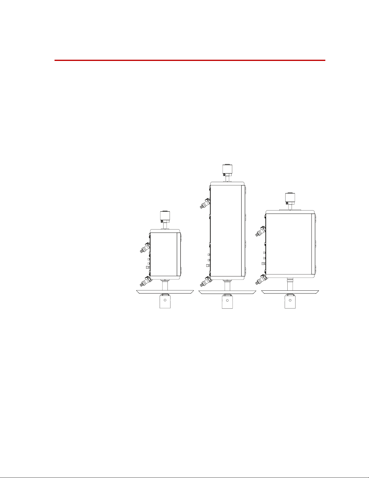
1 liter
10 liter
6 liter
About the Bionix EnviroBath Chamber
The MTS Bionix EnviroBath chamber is engineered for compatibility with MTS
Landmark and MTS Insight load frames. The Bionix EnviroBath chamber is also
compatible with the MTS Model 810, Model 858, Mini Bionix load frames, and
legacy EM load frames (such as Alliance, QTest and Synergie). It has an acrylic
chamber and its transparent walls allow easy viewing when non-opaque fluids
are employed in the test. The walls are compatible with the relatively moderate
temperatures typically employed in simulating the biomaterials service
environment.
The Bionix EnviroBath chamber facilitates accurate and efficient mechanical
testing of medical devices and biomaterial specimens in fluids heated to body
temperatures. Engineered for biomedical and general material test applications,
the Bionix EnviroBath chamber is easy to set up, operate, and maintain. It is
available in a range of volume configurations to accommodate a broad variety of
test specimens. A universal adapter design ensures full compatibility with all
MTS electromechanical and servohydraulic load frame systems, as well as other
electromechanical test systems.
Bionix® EnviroBath™ Chamber Introduction
13
Page 14

Features include:
• Variety of volume configurations: 1 liter, 6 liters, 10 liters
• Supports saline and protein-based fluids
• Utilizes a wide selection of Bionix grips and fixtures
• Reliable fluid temperature control mechanism
• Optional protein-based fluid system
The designs accommodate a variety of fixture and specimen heights and provide
easy access for specimen and fixture attachment.
Mounting of the Bionix EnviroBath chamber uses an attachment kit that installs
directly onto the system load cell (servohydraulic) or the baseplate clevis adapter
(electromechanical). In addition, the 10 liter EnviroBath chamber has column
clamps for servohydraulic applications.
Constant temperature control is regulated by an external circulator bath. Low
level fluid sensors shut the system down if the fluid drops unexpectedly to preset
minimum levels.
The standard Bionix EnviroBath chamber system includes a chamber,
recirculating heating system, and lower attachment kit.
Optional pull-rods are used inside the environmental chamber. For some
configurations, a flexible bellows tightly seals these rods. The pull-rods are easily
attached to the load cell (mounted on the base plate of the load frame) and to the
crosshead.
The chamber works with both axial and axial-torsion grips designed by MTS to
withstand the corrosive environment of the chamber. For supported grips and
fixtures, see the “Compatibility Matrix” on page 16.
14
Introduction
Bionix® EnviroBath™ Chamber
Page 15

Bionix EnviroBath Chamber Specifications
General Specifications
T
EMPERATURE
Range 5°C above ambient to 40°C
(40°F above ambient to 104°F)
Stability ±2°C at 37°C (±3.6°F at 98.6°F)
POWER (V AC, HZ, A)
120 V AC, 50/60 Hz, 11 A
240 V AC, 50 Hz, 10 A
Capacity and Dimensions
M
ODEL VOLUME AXIAL FORCE TORSIONAL FORCE INTERNAL DIMENSIONS
*
1 1 liter 2.4 kN
(540 lbf)
6 6 liters 2.4 kN
(540 lbf)
10 10 liters 10 kN
(2248 lbf)
* Width x Height x Depth
28 N·m
(20.6 lbf·ft)
28 N·m
(20.6 lbf·ft)
100 N·m
(73.7 lbf·ft)
X H X D)
(W
100 x 200 x 56 mm
4 x 8 x 2.2 in
130 x 480 x 100 mm
5 x 19 x 3.9 in
215 x 305 x 150 mm
8.5 x 12 x 5.8 in
Options
1610
Mister/Spray Option XX
Protein-Based Fluid XXX
Horizontal XX
Digital Temperature Monitor XXX
EXTERNAL DIMENSIONS
(W
X H X D)
180 x 295 x 95 mm
7 x 11.5 x 3.65 in
205 x 575 x 140 mm
8 x 22.5 x 5.5 in
295 x 395 x 190 mm
11.5 x 15.5 x 7.4 in
*
Bionix® EnviroBath™ Chamber Introduction
15
Page 16

Compatibility Matrix
G
RIPS AND FIXTURES 1610PART NUMBER
Bionix Vise Action Grips, 100 N XXX 100-186-411
Model 642.01 Bend Fixture XXX 100-201-458 (EM)
100-201-456 (SH)
Manual Thumb Screw XXX 100-167-987
Bionix Stainless Steel Compression Platens, 40 mm XXX100-203-455
Bionix Spring Action Grips XX 056-077-50x
Bionix Stainless Steel Compression Platens, 50 mm XX 100-182-229
Model 684.01A-42 Titanium Cam Action Grips XX 049-008-701
Bionix Vise Action Grips, 2 kN XX 100-174-783
Bionix Roller Action Grips, 1 kN XX 100-185-262
Model 642.01 Bend Fixture X 100-203-453 (EM)
100-203-454 (SH)
Bionix Stainless Steel Compression Platens, 100 mm X 100-182-227
Model 686.01A-42 Axial Torsional Grips X 051-882-2xx
Note: EnviroBath 10 chamber is compatible with customer-supplied spinal fixture per ASTM F1717-01.
Electromechanical Load Frames
1610
MTS Insight 1 & 2 standard length XX
MTS Insight 1 & 2 extended length XXX
MTS Insight 5 - 300 standard and extended length XXX
Legacy MTS load frames and Instron EM Load Frames Consult MTS
Servohydraulic Load Frames
1610
Bionix Tabletop Axial or Axial/Torsional
MTS Landmark
Legacy MTS load frames
‡
‡
* Additional adapter required.
† Extended columns required.
‡ Crosshead mounted actuator.
*
X
XXX
Consult MTS
*†
X
X
16
Introduction
Bionix® EnviroBath™ Chamber
Page 17

Safety Information
Hazard placard
placement
Hazard placards contain specific safety information and are affixed directly to the
system so they are plainly visible.
Each placard describes a system-related hazard. When possible, international
symbols (icons) are used to graphically indicate the type of hazard and the
placard label indicates its severity. In some instances, the placard may contain
text that describes the hazard, the potential result if the hazard is ignored, and
general instructions about how to avoid the hazard.
Know system limits Never rely on system limits such as mechanical limits or software limits to
protect you or any personnel. Limits are designed to minimize the chance of
accidental damage to test specimens or to equipment. Test all limits for proper
operation immediately before a test. Always use these limits and adjust them
properly.
High temperature
hazards
Toxicity of process
Instructions in setting up the heating circulator bath can be found in the vendor
documentation. The customer is responsible for ensuring that the process
temperature is set below the boiling point of the process fluid. Perform
overtemperature interlock testing as recommended by the heating circulator bath
documentation.
Be sure to follow the safety warnings in the MSDS for the process fluids.
fluid
Bionix® EnviroBath™ Chamber Safety Information
17
Page 18

Safety Information
18
Bionix® EnviroBath™ Chamber
Page 19
Installation
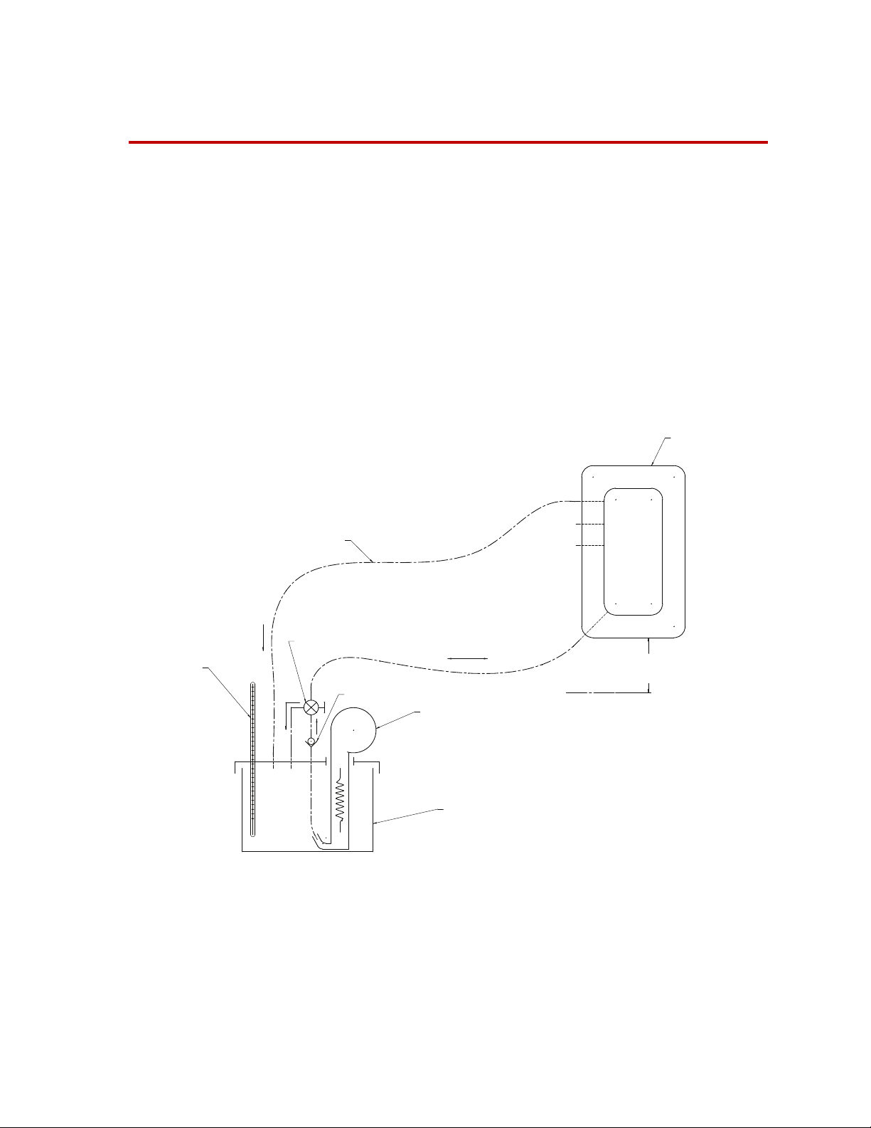
POSITIVE HEAD REQUIRED.
CHAMBER MUST BE ABOVE
PUMP AND CONNECT TUBING
FOR PROPER CIRCULATION AND DRAIN.
RESERVOIR WITH ACTIVE TEMP CONTROL FUNCTION
USE 1/2 INCH ID
(0.9% SALINE, MAX)
SILICONE EXTENSION TUBING
BIONIX CHAMBER
COUPLING
COUPLING
4.
FOR ALL CONNECTIONS
PRESSURE OF 1.6M [66"] (APPROX.)
QUICK
HEATER/CIRCULATOR
QUICK
THE CIRCULATION PUMP HAS LIMITED HEAD PRESSURE/FLOW PERFORMANCE. ZERO FLOW WILL OCCUR AT HEAD A
SPEED SETTING UNLESS A SAFE STEADY-STATE
FLUID LEVEL CAN BE ESTABLISHED.
IMPORTANT OPERATIONAL TIPS
:
GRAVITY DRAIN SYSTEM:
TUBE ROUTING FROM UPPER QUICK COUPLING MUST BE GENERALLY DOWNWARD. 1.
LOWER QUICK COUPLING MUST BE ABOVE RESERVOIR FOR CHAMBER TO DRAIN COMPLETELY WHEN PUMP IS SWITCHED 2.
OFF.
BEWARE OF OVER FILLING CHAMBER
: UNDER STEADY-STATE CIRCULATION CHAMBER FLUID LEVEL WILL TYPICALLY BE 2-4 3.
CM (3/4"-1-1/2") ABOVE UPPER QUICK COUPLING PORT.
DO NOT ALLOW IT TO REACH THE UPPER SURFACE OF THE
SAMPLE COMPARTMENT. THE CIRCULATION PUMP HAS "HIGH" AND "LOW" SPEED SETTING. DO NOT OPERATE AT HIGH
GLASS
THERMOMETER
3-WAY VALVE
CHECK VALVE
This section provides general installation guidelines and illustrations for the most
common mounting configurations.
General Installation Guidelines
Tubing and connector
requirements
Because of the variety of process fluids that can be used, MTS recommends
using only MTS supplied tubing and connectors. Use of improper tubing and
connectors could void any warranty.
Saline Distribution Assembly
The following illustration shows a typical setup using a saline distribution
system.
Bionix® EnviroBath™ Chamber Installation
19
Page 20

Serum Distribution Assembly
USE ONLY I/P-82 PUMP TUBING
AT SUCTION LINE
COUPLING
TEMP CONTROL FUNCTION
EXCEPT AT TUBE PUMP
(USE DEMINERALIZED WATER)
(1/2 INCH ID)
USE 1/2 INCH ID
THERMOMETER
USE 1/2 INCH ID
19L RESERVOIR - PROTEIN SERUM
FOR ALL CONNECTIONS
SILICONE EXTENSION TUBING
HEATER/CIRCULATOR
SILICONE EXTENSION TUBING
QUICK
QUICK
TUBE PUMP
BIONIX CHAMBER
COUPLING
COUPLING
QUICK
COUPLING
QUICK
28L RESERVOIR WITH ACTIVE
GLASS
AT PUMP
3-WAY VALVE
LOSS AND FLUID EVAPORATION.
IMPORTANT OPERATIONAL TIPS
:
GRAVITY DRAIN SYSTEM:
TUBING ROUTING FROM UPPER QUICK COUPLING MUST 1.
BE GENERALLY DOWNWARD.
LOWER QUICK COUPLING MUST BE ABOVE RESERVOIR 2.
FOR CHAMBER TO DRAIN COMPLETELY WHEN PUMP IS
SWITCHED OFF.
BEWARE OF OVER FILLING CHAMBER: UNDER STEADY-3.
STATE CIRCULATION CHAMBER FLUID LEVEL WILL
TYPICALLY BE 2-4 CM (3/4"-1-1/2") ABOVE UPPER QUICK
COUPLING PORT. DO NOT ALLOW IT TO REACH THE
UPPER SURFACE OF THE SAMPLE COMPARTMENT.
THE TUBING PUMP HAS A VARIABLE SPEED SETTING.4.
DETERMINE A PUMP SPEED WHICH RESULTS IN A SAFE
STEADY-STATE FLUID LEVEL.
DUAL RESERVOIR HEAT EXCHANGER
DUE TO LOSSES THROUGHOUT THE HEAT 5.
EXCHANGE SYSTEM, HEATER SET POINT
TEMPERATURE MAY NEED TO BE 5
C TO 10 C
ABOVE DESIRED TEST FLUID TEMPERATURE.
EXAMPLE: FOR A 37
C TEST FLUID TEMPERATURE
START WITH A HEATER SET POINT OF 47
C. ADJUST
AS NEEDED.
FOR BEST MEASUREMENT ACCURACY MAINTAIN 6.
125MM IMMERSION DEPTH FOR GLASS
THERMOMETER.
PLACE FOAM INSULATION AROUND CARBOY 7.
AND OVER HEATER RESERVOIR TO MINIMIZE HEAT
The following illustration shows a typical setup using a serum distribution
system. The illustration uses the EnviroBath 6/10 chamber as an example; the
setup for an EnviroBath 1 chamber would be similar.
Connect the hoses Cut tubing to the appropriate length and push the tubing onto the quick coupling.
20
Installation
Bionix® EnviroBath™ Chamber
Connect the quick coupling connectors to the circulating bath and EnviroBath
chamber connectors.
Page 21

Position the
circulating system
relative to the chamber
Determine the height at which the circulating system is placed relative to the
EnviroBath chamber to ensure proper fluid circulation and drain. Proper
orientation also minimizes the chance of fluid leaking from the top of the
chamber.
Head is the measure of the distance between the fluid out coupling on the
circulating bath and the bottom of the EnviroBath chamber. A positive head is
required for proper circulation and drain; the tubing routing from the upper quick
coupling to the circulating system should be generally downward. The lower
quick coupling must be above the reservoir for the chamber to drain completely
when the pump is switched to OFF.
Also consider head distance when setting up the system. The circulating pump
has limited head pressure/flow performance. Zero flow will occur at a head of
approximately 1.6 m (66 in).
Rate of process fluid
flow
Do not overfill the chamber. Under steady-state circulation, the chamber fluid
typically is 2–4 cm (0.75–1.5 in) above the upper quick coupling port. Do not
allow the fluid to reach the upper surface of the sample compartment. The
circulating pump has a high and low speed setting. Do not operate at high speed
setting unless a safe steady-state fluid level can be established.
Bionix® EnviroBath™ Chamber Installation
21
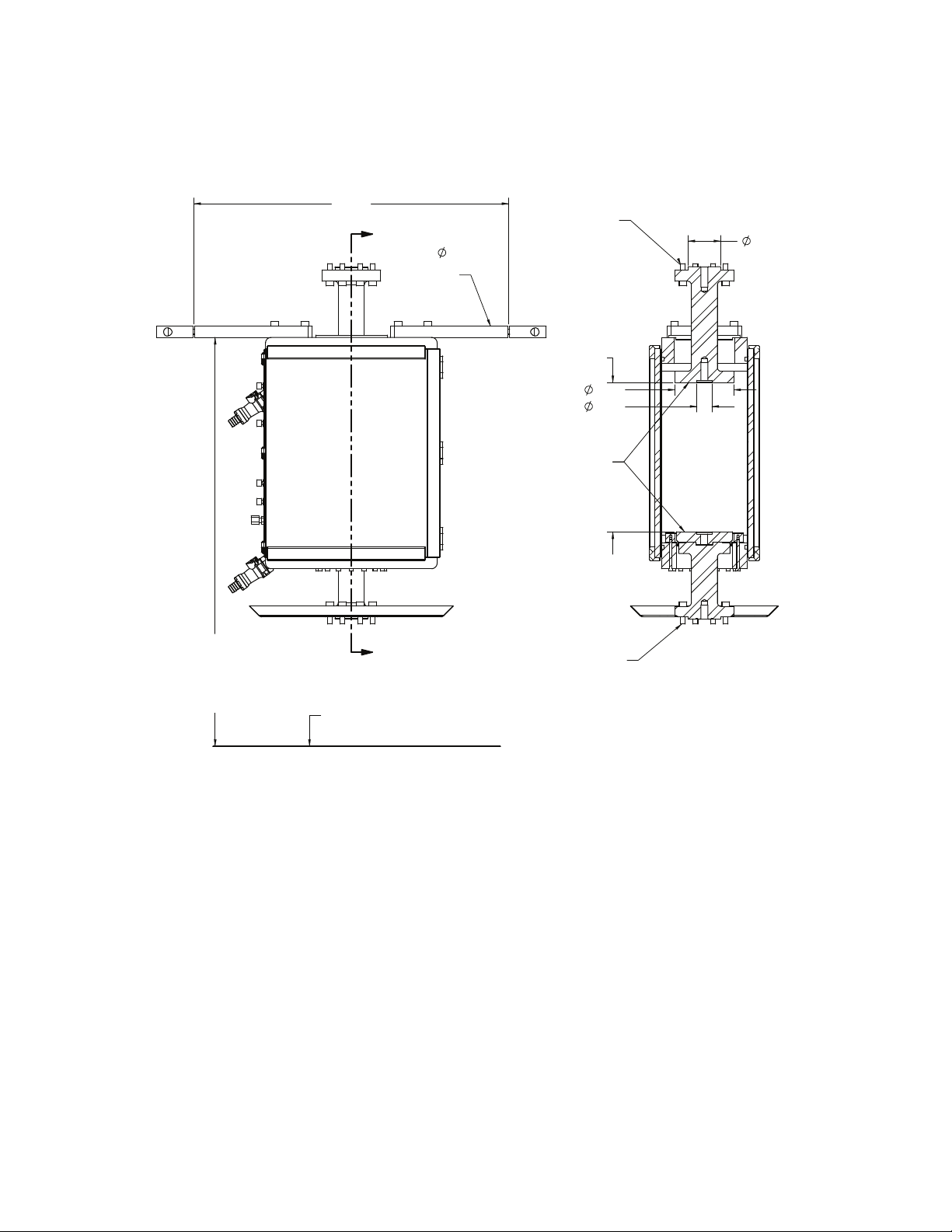
Page 22
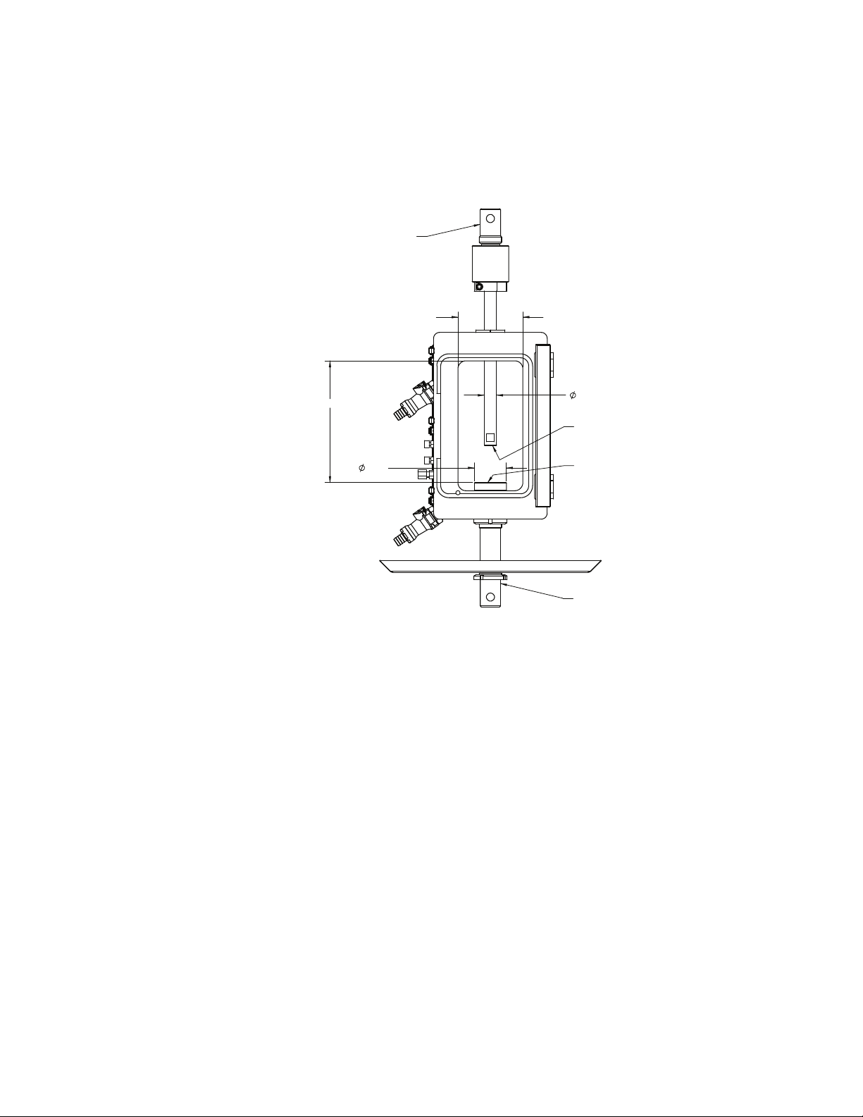
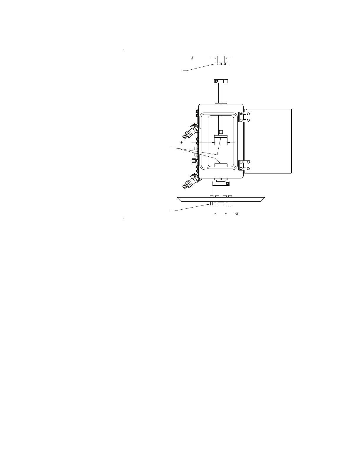
Bionix EnviroBath 1 Chamber Common Vertical Mounting Configurations
Note Adapters (for example “B”, “C”, “D”) referenced in the following
illustration are detailed in “Universal Adapters” on page 33.
Electromechanical,
2.4 kN (550 lb)
MALE UNIVERSAL ADPTR
"B", "C", "D"
4.000
7.500
1.970
.750
ACCESSORY MOUNT-UPPER
C
M6X1 ON
L
ACCESSORY MOUNTING-LOWER
C
M6 AT
L
4X M5X.8 ON A 1.688BC
COUPLING ASSY
MALE "D"
22
Installation
Bionix® EnviroBath™ Chamber
Page 23
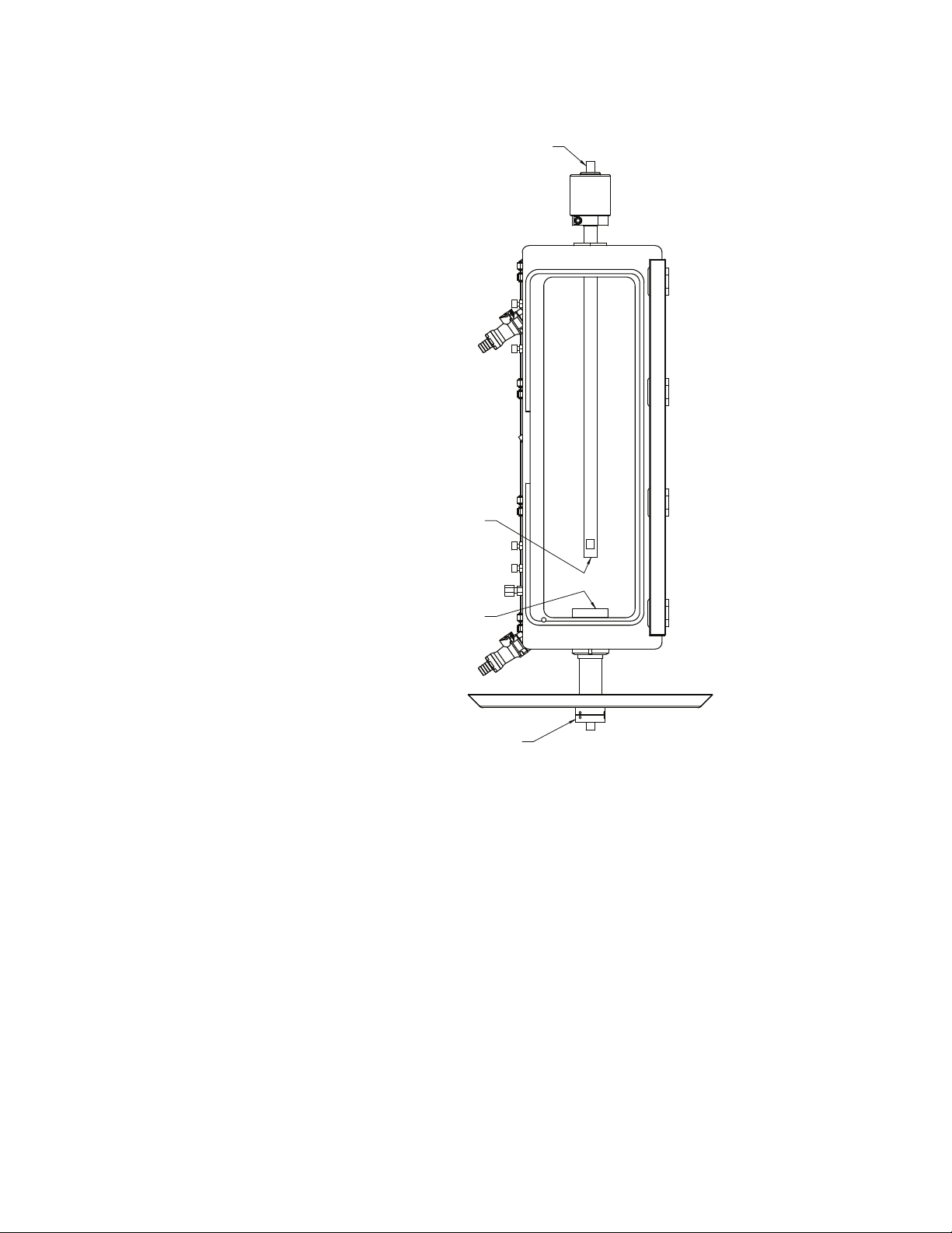
Servohydraulic, axial,
2.4 kN (550 lb)
LOAD FRAME ATTACHMENT:
M12 SCREW ON
C
L
ACCESSORY MOUNT-UPPER
M6X1 ON
ACCESSORY MOUNTING-LOWER
M6 AT
4X M5X.8 ON A 1.688BC
C
L
C
L
LOAD FRAME ATTACHMENT
M12X1.25 STUD AND
SPIRAL WASHER SET ON
C
L
Bionix® EnviroBath™ Chamber Installation
23
Page 24
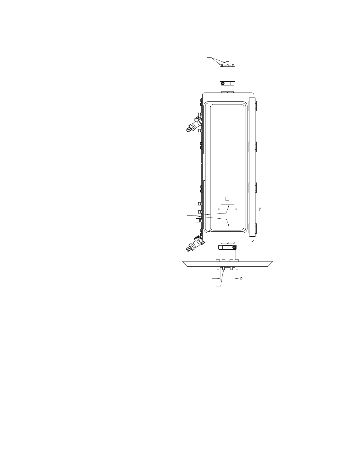
Servohydraulic.
4X M5X.8 ON A 1.688BC
M6 ON
ACCESSORY MOUNTING:
C
L
4X M5 SCREW ON A 1.688BC
C
L
M12 SCREW ON
LOAD FRAME ATTACHMENT:
8X M8 SCREW ON A 3.100 BC
LOAD FRAME ATTACHMENT:
PILOT
2.200
PILOT
1.125
1.980
axial/torsional
2.4 kN (550 lb)/
28 N·m (250 in-lb)
24
Installation
Bionix® EnviroBath™ Chamber
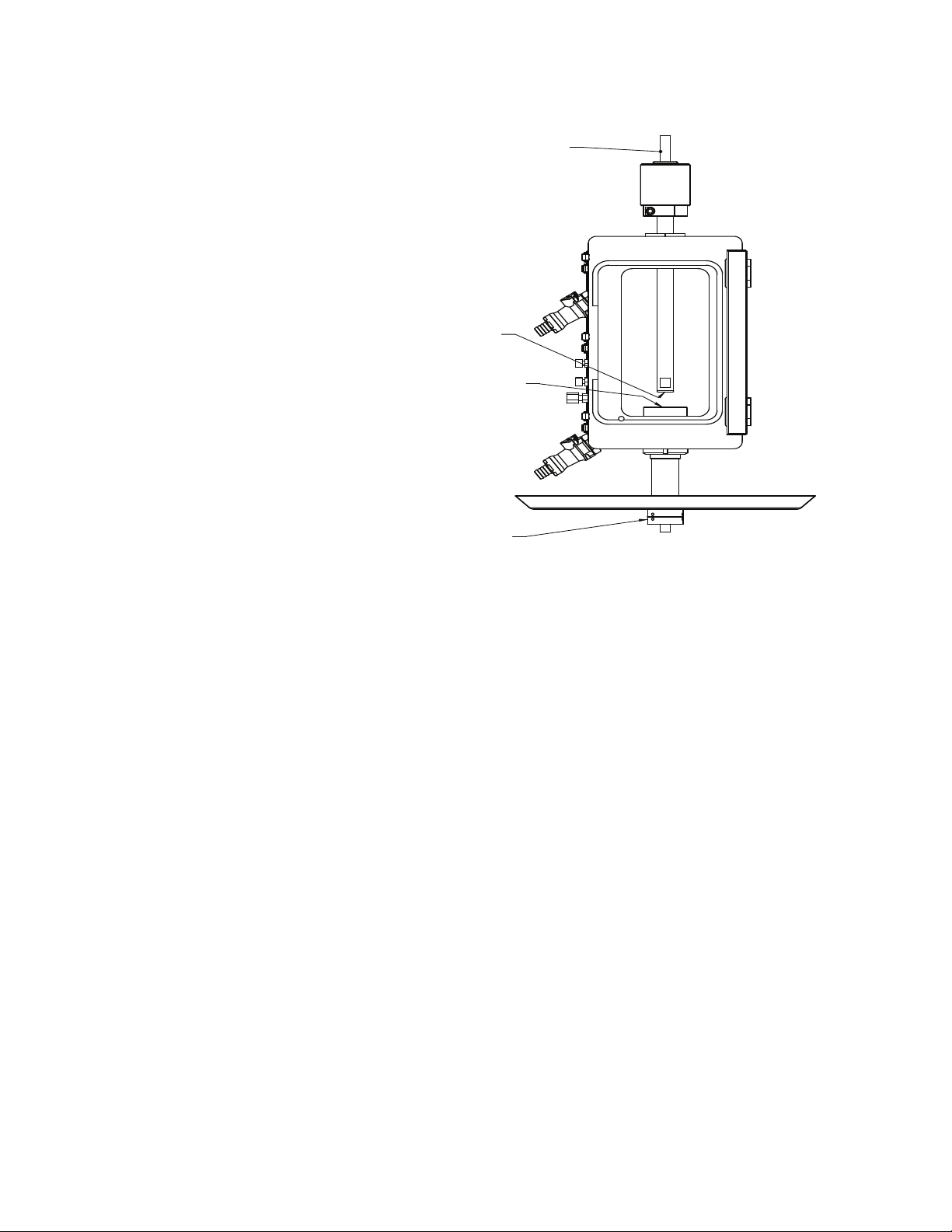
Page 25

Bionix EnviroBath 6 Chamber Common Mounting Configurations
M6 AT
LOWER
ADAPTER
C
L
M6X1 ON
UNIVERSAL
C
L
MOUNT-UPPER
COUPLING ASSY
4X M5X.8 ON A 1.688BC
"B", "C", "D"
MALE
MALE "D"
ACCESSORY MOUNTING-
ACCESSORY
1.970
.750
18.500
5.100
Note Adapters (for example “B”, “C”, “D”) referenced in the following
illustration are detailed in “Universal Adapters” on page 33.
Electromechanical,
vertical, 2.4 kN (550 lb)
Bionix® EnviroBath™ Chamber Installation
25
Page 26
Servohydraulic, axial,
2.4 kN (550 lb)
LOAD FRAME ATTACHMENT:
M12 SCREW ON
ACCESSORY
MOUNT-UPPER
M6X1 ON
C
L
C
L
ACCESSORY
MOUNTING-LOWER
4X M5X.8 ON A
LOAD FRAME ATTACHMENT
M12X1.25 STUD AND
SPIRAL WASHER SET ON
M6 AT
1.688BC
C
L
C
L
26
Installation
Bionix® EnviroBath™ Chamber
Page 27
Servohydraulic.
LOAD FRAME ATTACHMENT:
8X M8 SCREW ON A 3.100 BC
1.688BC
4X M5X.8 ON A
C
L
4X M5 SCREW ON A 1.688BC
C
L
LOAD FRAME ATTACHMENT:
M12 SCREW ON
ACCESSORY
MOUNTING:
M6 ON
2.200
1.980
axial/torsional
2.4 kN (550 lb)/
28 N·m (250 in-lb)
Bionix® EnviroBath™ Chamber Installation
27
Page 28

Bionix EnviroBath 10 Chamber Common Mounting Configurations
"B", "C", "D"
MALE UNIVERSAL ADPTR
MALE UNIVERSAL ADAPTER
"D"
.750
B
B
C
L
4X M5X.8 ON A 1.688BC
M6X1 ON
ACCESSORY MOUNT-LOWER
M12X1.25 ON
C
L
ACCESSORY MOUNT-UPPER
SECTION B-B
M6X1 ON
C
L
5.750
Note Adapters (for example “B”, “C”, “D”) referenced in the following
illustration are detailed in “Universal Adapters” on page 33.
Electromechanical,
2.4 kN (550 lb)
28
Installation
Bionix® EnviroBath™ Chamber
Page 29
Electromechanical,
10 kN (2.2 kip)
8.500
MALE UNIVERSAL ADAPTER
"D"
11.400
1.250
5.350
ACCESSORY MOUNT-UPPER
M12X1.25 ON
ACCESSORY MOUNT-LOWER
M12X1.25 ON
M6X1 ON
4X M5X.8 ON A 1.688BC
MALE UNIVERSAL ADAPTER
"D"
C
L
C
L
C
L
Bionix® EnviroBath™ Chamber Installation
29
Page 30
Servohydraulic,
22.3
[661.19 AXIAL XDCR]
23.7
27.4
[662.20X-05 A/T XDCR]
[662.20X-03/-04 A/T XDCR]
MNT
3.00
COLUMN
T-SLOT TABLE SURFACE
21.110
A
A
8X M8X1.25 ON A 3.100BC
ON A 3.100BC
C
L
5/16-18UNC
ON A 3.100BC
ACCESSORY MOUNTING:
4X M5X.8 ON A 1.688BC
M12 ON
SECTION A-A
8X M8X1.25 OR
5/16-18UNC
C
L
M12X1.25 AT
LOAD FRAME ATTACHMENT:
LOAD FRAME ATTACHMENT:
M12X1.25 AT
C
L
8X M8X1.25 OR
3.930
1.000
2.201
11.200 MAX
10 kN (2.2 kip)
30
Installation
Bionix® EnviroBath™ Chamber
Page 31
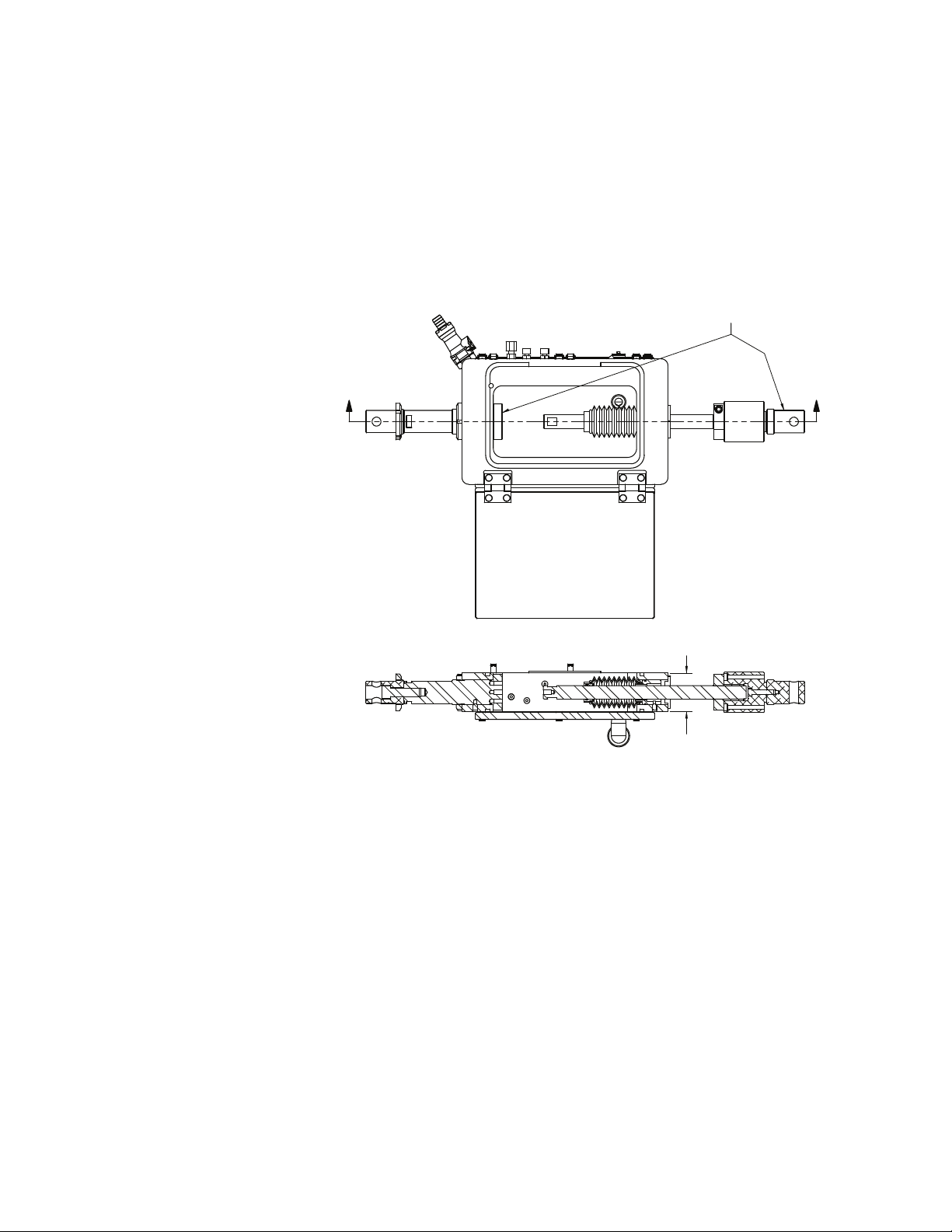
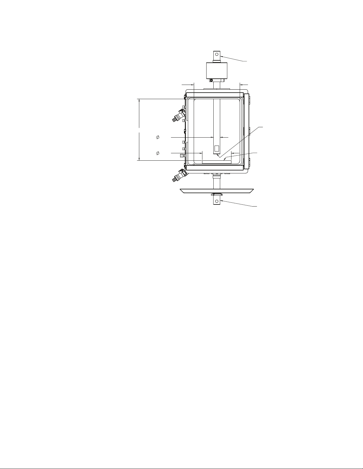
Horizontal Mounting Configurations
AS VERTICAL
MOUNTINGS SAME
LOAD FRAME AND ACCESSORY
A
A
SECTION A-A
2.150
TOP VIEW
The Bionix EnviroBath 1 chamber and Bionix EnviroBath 6 chamber can be
horizontally mounted in the MTS Insight 1 kN and 2 kN single column load
frames.
Note Adapters (for example “B”, “C”, “D”) referenced in the following
illustration are detailed in “Universal Adapters” on page 33.
Horizontal, Bionix
EnviroBath 1,
Electromechanical,
2.4 kN (550 lb)
Bionix® EnviroBath™ Chamber Installation
31
Page 32

Horizontal, Bionix
AS E/M VERTICAL
MOUNTINGS SAME
LOAD FRAME AND ACCESSORY
TOP VIEW
EnviroBath 6,
Electromechanical,
2.4 kN (550 lb)
32
Installation
Bionix® EnviroBath™ Chamber
Page 33

Universal Adapters
Clevis Pin
Connection Type
Attachment
CLEVIS PIN CONNECTION TYPE TYPE BTYPE CTYPE D
Load Up to 10 N Up to 200 N Up to 150 kN
Clevis Diameter (X) 0.50 in 0.625 in 1.25 in
Pin Diameter (Y) 0.187 in 0.25 in 0.50 in
Upper Grip Connection (male) Bm Cm Dm
Lower Grip Connection (male) Dm Dm Dm
Upper Load Frame Connection (female) Bf Cf Df
Lower Load Frame Connection (female) Df Df
Df
Bionix® EnviroBath™ Chamber Installation
33
Page 34

34
Installation
Bionix® EnviroBath™ Chamber
Page 35

Operation
Bionix EnviroBath
chamber
Heating circulator
bath operation
Other than the hose connections and closing and latching the door before filling
the chamber with fluid, all operation is performed using the heating circulator
bath.
A manual describing operation of the heating circulator bath is provided by the
vendor.
Process fluids Use only recommended fluids:
• Water
• Saline
• Protein serum
Set limits before
testing
Limits should be set such that grips and fixtures cannot damage the EnviroBath
chamber during setup and testing.
For electromechanical test frames, limits are usually set by positioning physical
switches to stop crosshead travel when the limit is reached. For more
information, see the individual frame product manual.
For servohydraulic test frames, limits are usually set in the control software. For
more information, see setting detectors in the controller software manual for
additional information.
Elevated temperature
operation
For elevated temperature operation information, see circulating bath vendor
documentation
Fluids used in the EnviroBath chamber can reach boiling point.
Boiling fluid can cause personal injury and equipment damage.
When operating the EnviroBath chamber at elevated temperature, it is the
customer’s responsibility to ensure the temperature set point is below the boiling
point of the process fluid.
Bionix® EnviroBath™ Chamber Operation
35
Page 36

Resonant frequency
The drip pan has a resonant frequency of about 10 Hz and vibrates if the
system is operated around that frequency.
A vibrating drip pan can cause fluid spills. Vibration over time can result in
equipment damage.
Do not operate the system at approximately 10 Hz.
36
Operation
Bionix® EnviroBath™ Chamber
Page 37

Maintenance
Periodic cleaning Maintenance of the Bionix EnviroBath chamber consists of periodic cleaning and
seal inspection.
Before cleaning, disassemble the chamber and extension rod feed-thru seals to
the extent necessary to inspect for build-up of deposits.
To clean the unit, use a mild detergent and a clean, lint-free cloth. Rinse
thoroughly to remove detergent deposits and dry with a clean, lint-free cloth.
Seal inspection O-ring seals, fittings, and pipe thread sealant should be inspected at each use and
replaced if leakage is noticed. When replacing seals, ensure that the seam is at the
top. The seals can be removed by pulling them out of the channel. The seals can
be installed by starting with one end top center, and pushing the seal into the
groove with a thumb or finger. Never use a sharp objects to install seals.
Heating circulator
bath operation
A manual describing maintenance of the heating circulator bath is provided by
the vendor.
Bionix® EnviroBath™ Chamber Maintenance
37
Page 38

38
Maintenance
Bionix® EnviroBath™ Chamber
Page 39

Page 40

m
MTS Systems Corporation
14000 Technology Drive
Eden Prairie, Minnesota 55344-2290 USA
Toll Free Phone: 800-328-2255
(within the U.S. or Canada)
Phone: 952-937-4000
(outside the U.S. or Canada)
Fax: 952-937-4515
E-mail: info@mts.com
Internet: www.mts.com
ISO 9001 Certified QMS
 Loading...