

Page 1

m
be certain.
Advantage™ Pneumatic Grips
Product Information
100-013-660 L
Page 2

Copyright information © 2012 MTS Systems Corporation. All rights reserved.
Trademark information MTS is a registered trademark of MTS Systems Corporation within the United
States. These trademarks may be protected in other countries.
Molykote is a registered trademark of Carleton-Stuart Corporation. Surfalloy is a
trademark of Alloying Surfaces Incorporated. Scotch-Brite is a trademark of 3M.
All other trademarks or service marks are property of their respective owners.
Publication information
Manual Part Number Publication Date
100-013-660 A October 2000
100-013-660 B December 2000
100-013-660 C January 2001
100-013-660 D June 2001
100-013-660 E June 2001
100-013-660 F September 2001
100-013-660 G October 2004
100-013-660 H November 2004
100-013-660 J February 2005
100-013-660 K November 2009
100-013-660 L August 2012
2
Advantage™ Pneumatic Grips
Page 3

Contents
Technical Support 5
How to Get Technical Support 5
Before You Contact MTS 6
If You Contact MTS by Phone 7
Problem Submittal Form in MTS Manuals 8
Preface 11
Before You Begin 11
Conventions 12
Documentation Conventions 12
Introduction 15
Functional Description 17
Specifications 20
Safety Information 21
General Safety Practices: Grips and Fixtures 21
Hazard Placard Placement 27
Power Loss Consideration 27
Installation 29
Installation Using the Mounting Pin 30
Installation Without Using the Mounting Pin 32
Connecting the Air Supply 35
Advantage™ Pneumatic Grips Contents
3
Page 4

Operation 39
Selecting Face Surfaces 40
Grip Faces for the 10 N Grips 41
Grip Faces for the 200 N and 2000 N Grips 42
Grip Faces for the 10,000 N Grips 45
Changing Face Surfaces 47
Changing Wedges 48
Installing a Specimen 50
Adjusting the Air Supply Pressure 53
Maintenance 55
4
Contents
Advantage™ Pneumatic Grips
Page 5

Technical Support
How to Get Technical Support
Start with your
manuals
Technical support
methods
The manuals supplied by MTS provide most of the information you need to use
and maintain your equipment. If your equipment includes software, look for
online help and README files that contain additional product information.
If you cannot find answers to your technical questions from these sources, you
can use the Internet, e-mail, telephone, or fax to contact MTS for assistance.
MTS provides a full range of support services after your system is installed. If
you have any questions about a system or product, contact Technical Support in
one of the following ways.
www.mts.com The web site provides access to our technical support staff by means of an
onlineform:
www.mts.com > Contact MTS > Service & Technical Support button
E-mail tech.support@mts.com
Telephone MTS Call Center 800-328-2255
Weekdays 7:00 A.M. to 5:00 P.M., Central Time
Fax 952-937-4515
Please include “Technical Support” in the subject line.
Outside the U.S. For technical support outside the United States, contact your local sales and
service office. For a list of worldwide sales and service locations and contact
information, use the Global MTS link at the MTS web site:
www.mts.com > Global MTS > (choose your region in the right-hand
column) > (choose the location closest to you)
Advantage™ Pneumatic Grips Technical Support
5
Page 6

Before You Contact MTS
MTS can help you more efficiently if you have the following information
available when you contact us for support.
Know your site
number and system
number
Know information from
prior technical
The site number contains your company number and identifies your equipment
type (such as material testing or simulation). The number is typically written on a
label on your equipment before the system leaves MTS. If you do not know your
MTS site number, contact your sales engineer.
Example site number: 571167
When you have more than one MTS system, the system job number identifies
your system. You can find your job number in your order paperwork.
Example system number: US1.42460
If you have contacted MTS about this problem before, we can recall your file
based on the:
assistance
• MTS notification number
• Name of the person who helped you
Identify the problem Describe the problem and know the answers to the following questions:
• How long and how often has the problem occurred?
• Can you reproduce the problem?
• Were any hardware or software changes made to the system before the
problem started?
Technical Support
6
• What are the equipment model numbers?
• What is the controller model (if applicable)?
• What is the system configuration?
Advantage™ Pneumatic Grips
Page 7

Know relevant
computer information
For a computer problem, have the following information available:
• Manufacturer’s name and model number
• Operating software type and service patch information
• Amount of system memory
• Amount of free space on the hard drive where the application resides
• Current status of hard-drive fragmentation
• Connection status to a corporate network
Know relevant
For software application problems, have the following information available:
software information
• The software application’s name, version number, build number, and (if
available) software patch number. This information can typically be found
in the About selection in the Help menu.
• The names of other applications on your computer, such as:
– Anti-virus software
– Screen savers
– Keyboard enhancers
– Print spoolers
– Messaging applications
If You Contact MTS by Phone
A Call Center agent registers your call before connecting you with a technical
support specialist. The agent asks you for your:
• Site number
• Name
• Company name
• Company address
• Phone number where you can be reached
If your issue has a notification number, please provide that number. A new issue
will be assigned a unique notification number.
Advantage™ Pneumatic Grips Technical Support
7
Page 8

Identify system type To enable the Call Center agent to connect you with the most qualified technical
support specialist available, identify your system as one of the following types:
• Electromechanical material test system
• Hydromechanical material test system
• Vehicle test system
• Vehicle component test system
• Aero test system
Be prepared to
Prepare to perform troubleshooting while on the phone:
troubleshoot
• Call from a telephone close to the system so that you can implement
suggestions made over the phone.
• Have the original operating and application software media available.
• If you are not familiar with all aspects of the equipment operation, have an
experienced user nearby to assist you.
Write down relevant
In case Technical Support must call you:
information
• Verify the notification number.
• Record the name of the person who helped you.
• Write down any specific instructions.
After you call MTS logs and tracks all calls to ensure that you receive assistance for your
problem or request. If you have questions about the status of your problem or
have additional information to report, please contact Technical Support again and
provide your original notification number.
Problem Submittal Form in MTS Manuals
Use the Problem Submittal Form to communicate problems with your software,
hardware, manuals, or service that are not resolved to your satisfaction through
the technical support process. The form includes check boxes that allow you to
indicate the urgency of your problem and your expectation of an acceptable
response time. We guarantee a timely response—your feedback is important to
us.
Technical Support
8
Advantage™ Pneumatic Grips
Page 9

Access the Problem Submittal Form:
• In the back of many MTS manuals (postage paid form to be mailed to MTS)
• www.mts.com > Contact Us > Problem Submittal Form button (electronic
form to be e-mailed to MTS)
Advantage™ Pneumatic Grips Technical Support
9
Page 10

Technical Support
10
Advantage™ Pneumatic Grips
Page 11

Preface
Before You Begin
Safety first! Before you use your MTS product or system, read and understand the Safety
manual and any other safety information provided with your system. Improper
installation, operation, or maintenance can result in hazardous conditions that can
cause severe personal injury or death, or damage to your equipment and
specimen. Again, read and understand the safety information provided with your
system before you continue. It is very important that you remain aware of
hazards that apply to your system.
Other MTS manuals In addition to this manual, you may receive additional manuals in paper or
electronic form.
You may also receive an MTS System Documentation CD. It contains an
electronic copy of the manuals that pertain to your test system, such as:
• Hydraulic and mechanical component manuals
• Assembly drawings
• Parts lists
• Operation manual
• Preventive maintenance manual
Controller and application software manuals are typically included on the
software CD distribution disc(s).
Advantage™ Pneumatic Grips Preface
11
Page 12

Conventions
DANGER
WARNING
CAUTION
Conventions
Documentation Conventions
The following paragraphs describe some of the conventions that are used in your
MTS manuals.
Hazard conventions Hazard notices may be embedded in this manual. These notices contain safety
information that is specific to the activity to be performed. Hazard notices
immediately precede the step or procedure that may lead to an associated hazard.
Read all hazard notices carefully and follow all directions and recommendations.
Three different levels of hazard notices may appear in your manuals. Following
are examples of all three levels.
Note For general safety information, see the safety information provided with
your system.
Danger notices indicate the presence of a hazard with a high level of risk which,
if ignored, will result in death, severe personal injury, or substantial property
damage.
12
Warning notices indicate the presence of a hazard with a medium level of risk
which, if ignored, can result in death, severe personal injury, or substantial
property damage.
Caution notices indicate the presence of a hazard with a low level of risk which,
if ignored, could cause moderate or minor personal injury or equipment damage,
or could endanger test integrity.
Notes Notes provide additional information about operating your system or highlight
easily overlooked items. For example:
Note Resources that are put back on the hardware lists show up at the end of
the list.
Special terms The first occurrence of special terms is shown in italics.
Preface
Advantage™ Pneumatic Grips
Page 13

Conventions
Illustrations Illustrations appear in this manual to clarify text. They are examples only and do
not necessarily represent your actual system configuration, test application, or
software.
Electronic manual
conventions
This manual is available as an electronic document in the Portable Document
File (PDF) format. It can be viewed on any computer that has Adobe Acrobat
Reader installed.
Hypertext links The electronic document has many hypertext links displayed in a blue font. All
blue words in the body text, along with all contents entries and index page
numbers, are hypertext links. When you click a hypertext link, the application
jumps to the corresponding topic.
Advantage™ Pneumatic Grips Preface
13
Page 14

Conventions
14
Preface
Advantage™ Pneumatic Grips
Page 15
Introduction
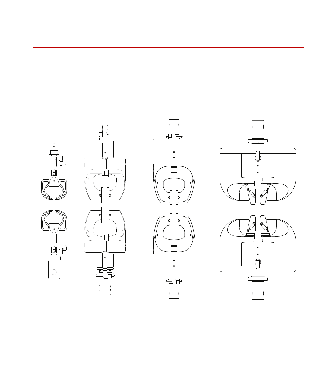
10 N 200 N 2000 N 10,000 N
Contents Functional Description 17
The Advantage™ Pneumatic Grips hold a test specimen in a load unit for static
tension testing. Most of the grips accommodate flat-surfaced specimens only, the
10,000 N high tensile grip can clamp flat and round specimens.
Specifications 20
Advantage Pneumatic Grip Family
Advantage™ Pneumatic Grips Introduction
15
Page 16

What you need to
know
This manual assumes that you know how to use your controller. See the
appropriate manual for information about performing any controller-related step
in this manual’s procedures. You are expected to know how to:
• Turn main power on and off (electromechanical systems) or turning
hydraulic pressure on and off (servohydraulic systems)
• Manually adjust the actuator or crosshead position
• Adjust the air supply pressure
• Use the air controller clamping controls (if available)
16
Introduction
Advantage™ Pneumatic Grips
Page 17

Functional Description
The Advantage Pneumatic Grips are designed for static tension testing. The
pneumatic grips require an external air supply to provide filtered, dry air to the
grips. Applying air to the grips cause them to clamp and removing the air causes
them to release. There are a variety of ways to control the air to the grips. The
grips can be installed in an electromechanical load frame or a servohydraulic load
unit with the appropriate adapter kit.
Functional Description
Advantage 10 N
applications
Advantage
200 N/2000 N
applications
The 10 N (2 lbf) capacity pneumatic grips are designed for low tensile
applications and testing thin specimens with low breaking strengths like the gold
wire in electronics, tungsten wire, thermocouples, gels, and plastic films.
These grips feature dual acting, swivel faces that simultaneously move to the
centerline of the grip and eliminate the bending strains on your specimen that can
invalidate your test results. The ability to swivel lets these faces conform to any
variations in your specimen’s geometry. The grip also has a self-aligning feature
which allows the grips to maintain alignment while actuated.
The 200 N (40 lbf) and 2000 N (400 lbf) capacity pneumatic grips can be used to
test a variety of thin films, sheets, and tapes.
The low and medium tensile models feature dual acting grip faces that
simultaneously move to the centerline of the grip. This assures correct specimen
alignment and removes the bending strains that can invalidate test results.
The design of these grips let you quickly and easily load and align your
specimens. They also feature an area above the grip faces that is large enough for
you to load the specimens while holding them with your fingers.
The weight of the 200 N grip is low enough to allow it to be used with 100 N
force transducers.
Advantage™ Pneumatic Grips Introduction
17
Page 18

Functional Description
Advantage 10,000 N
applications
Grip faces
and wedges
The 10,000 N (2,200 lbf) capacity pneumatic grips are designed for performing
tensile tests on a variety of materials including elastomers, plastics, rigid and
semi-rigid films, and sheets. These grips can use a variety of flat, round, and veeshaped wedges. They feature dual acting grip faces that simultaneously move to
the centerline of the grip.
The grips offer quick and easy specimen insertion. This model also features a
constant clamping load to protect your specimens from damage due to slippage.
The weight of the 10,000 N grip is low enough to allow it to be used with 5,000
N force transducers.
The 10 N, 200 N, and 2000 N grips use grip faces to contact and hold a specimen.
The 10,000 N grips use wedges to contact and hold a specimen. Several surfaces
are available for the faces and grips (not all surfaces are available for all grips).
• Corrugated for gripping smooth and flexible specimens
• Serrated for gripping soft material
• Smooth rubber coating for extra gripping protection of thin delicate
specimens (in some cases the smooth faces will slip below the rated capacity
of the grip)
• Matte rubber coating for more gripping power than smooth rubber coated
faces
Electromechanical
Servohydraulic
Introduction
18
systems
systems
• Corrugated rubber coating for more gripping power than the matte rubber
coated faces
• Diamond tipped for more aggressive gripping needs
• Grab test for gripping fabric specimens
• Line contact for gripping rubber, latex, and cable sheath
Installing the grips in an electromechanical system involves mounting one grip to
the base of the load frame and the other grip to the crosshead of the load frame.
Standard mounting pins are used.
Installing the grips in a servohydraulic system involves attaching one grip onto
the end of the load unit actuator rod and one grip to the load unit force transducer.
The standard mounting pin can be removed so the grip can be bolted directly to
the actuator or load transducer.
Advantage™ Pneumatic Grips
Page 19

Functional Description
Adapters Each grip assembly includes a set of standard mounting pins. Some grip
assemblies include different size mounting pins for the upper and lower grips.
Optional adapters are available to install the grips in some specific load frames or
load units.
Optional mounting adapters allow the grips to be installed on an actuator and
load transducer of a servohydraulic load unit. The adapter allows the use of the
standard mounting pin in servohydraulic systems.
Advantage™ Pneumatic Grips Introduction
19
Page 20

Specifications
WARNING
Specifications
This section lists the specifications for the Advantage Pneumatic Grips.
General Specifications
P
ARAMETER SPECIFICATION
Temperature range
Air supply must provide clean dry air at 5.5 bar (80 psi)
* Between -40°C and 0°C moisture will accumulate on exposed parts and freeze.
Moisture compromises the functionality of the grips at this temperature range. Use
an external clamp/release switch for this temperature range.
You can burn yourself if you touch the clamping knobs on the grips when
they are hotter than 55°C (130°F)
Use protective gloves if it is necessary to manually clamp or unclamp the grips at
elevated temperatures. Or add remote clamping control to the grips (see “Air
connection kits” on page 36).
°C to 200°C (-40°F to 400°F)
-40
*
Model Specific Specifications
Model Capacity
Clamping Force
*
Upper Grip Weight Max Specimen
Thickness
10 N 10 N (2 lbf) ~31 N (7 lbf) ~0.27 kg (0.6 lb) 5 mm (0.2 in)
200 N 200 N (40 lbf) ~623 N (140 lbf) ~0.91 kg (2 lb) 10 mm (0.39 in)
2000 N 2000 N (400 lbf) ~7100 N (1600 lbf) ~2.7 kg (6 lb) 12 mm (0.47 in)
10,000 N 10 kN (2200 lbf) ~17 kN (4000 lbf) ~6.8 kg (15 lb) 25 mm (1 in)
* At 5.5 bars (80 psi).
20
Introduction
Advantage™ Pneumatic Grips
Page 21

Safety Information
General Safety Practices: Grips and Fixtures
Typically, grips and fixtures are part of equipment used in MTS testing systems.
This section provides general information about safety issues that pertain to
systems that use grips and fixtures. These issues include statements to the
intended use and foreseeable misuse of the system and definition for the
graphical hazard labeling that is affixed to your product, and other (more general)
safety information that relates to the high-pressure and high-performance
characteristics of MTS servohydraulic and electromechanical systems.
When you prepare to operate a system that includes grips or fixtures, ensure the
following:
• Do not use or allow personnel to operate the system who are not
experienced, trained, or educated in the inherent dangers associated with
high-performance servo hydraulics and who are not experienced, trained, or
educated with regard to the intended operation as it applies to this test
system.
• Do not disable safety components or features (including limit detectors,
light curtains, or proximity switches/detectors).
• Do not attempt to operate the system without appropriate personal safety
gear (for example, hearing, hand, and eye protection).
• Do not modify the system or replace system components using parts that are
not MTS component parts or effect repairs using parts or components that
are not manufactured to MTS specifications.
• Do not operate the grips or fixtures in an explosive atmosphere.
• Do not use the system in a test area where uncontrolled access to the test
system is allowed when the system is in operation.
• For servohydraulic systems, do not operate the system unless an interlock is
installed to monitor supply pressure into the HSM and initiate a system
interlock if a low or no pressure event occurs.
If you have system related responsibilities (that is, if you are an operator, service
engineer, or maintenance person), you should study safety information carefully
before you attempt to perform any test system procedure.
Advantage™ Pneumatic Grips Safety Information
21
Page 22

You should receive training on this system or a similar system to ensure a
thorough knowledge of your equipment and the safety issues that are associated
with its use. In addition, you should gain an understanding of system functions
by studying the other manuals supplied with your test system. Contact MTS for
information about the content and dates of training classes that are offered.
It is very important that you study the following safety information to ensure that
your facility procedures and the system’s operating environment do not
contribute to or result in a hazardous situation. Remember, you cannot eliminate
all the hazards associated with this system, so you must learn and remain aware
of the hazards that apply to your system at all times. Use these safety guidelines
to help learn and identify hazards so that you can establish appropriate training
and operating procedures and acquire appropriate safety equipment (such as
gloves, goggles, and hearing protection).
Each test system operates within a unique environment which includes the
following known variables:
• Facility variables (facility variables include the structure, atmosphere, and
utilities)
• Unauthorized customer modifications to the equipment
• Operator experience and specialization
• Test specimens
Because of these variables (and the possibility of others), your system can
operate under unforeseen circumstances that can result in an operating
environment with unknown hazards.
Improper installation, operation, or maintenance of your system can result in
hazardous conditions that can cause death, personal injury, or damage to the
equipment or to the specimen. Common sense and a thorough knowledge of the
system’s operating capabilities can help to determine an appropriate and safe
approach to its operation.
Read all manuals Study the contents of this manual and the other manuals provided with your
system before attempting to perform any system function for the first time.
Procedures that seem relatively simple or intuitively obvious may require a
complete understanding of system operation to avoid unsafe or dangerous
situations.
Safety Information
22
Advantage™ Pneumatic Grips
Page 23

Avoid pinch/crush
points
Pinch points exist between the parts of the grip or fixture that contact the
specimen. Be aware of these pinch points when installing a specimen or working
around the grip or fixture during test setup. High forces generated when grip
pressure is activated can pinch, cut, or crush anything in the path of the grip/
fixture specimen contact area and cause serious injury. Stay clear of any potential
pinch points.
A crush point exists between the grips. Whenever possible, use tongs or similar
tool when handling the specimen during specimen installation. Never allow any
part of your body to enter the path of machine movement or to touch moving
machinery, linkages, hoses, cables, specimens, and so forth. These present
serious crush points or pinch points.
Locate and read
hazard placards/labels
Know facility safe
procedures
Find, read, and follow the hazard placard instructions located on the equipment.
These placards are placed strategically on the equipment to call attention to areas
such as known crush points, electrical voltage, and high pressure hazards.
Most facilities have internal procedures and rules regarding safe practices within
the facility. Be aware of these safe practices and incorporate them into your daily
operation of the system.
Know controls Before you operate the system for the first time, make a trial run through the
operating procedures with the power off. Locate all hardware and software
controls and know what their functions are and what adjustments they require. If
any control function or operating adjustment is not clear, review the applicable
information until you understand it thoroughly.
Know specimen
properties
Advantage™ Pneumatic Grips Safety Information
The user is responsible for understanding the characteristics of the test specimen.
Be sure to use appropriate personal protective equipment (clothing, hand gloves,
eye protection etc.).
Use protective guards such as cages, enclosures, and special laboratory layouts
when you work with hazardous test specimens (for example, brittle or
fragmenting materials or materials that are internally pressurized).
23
Page 24

Have first aid available Accidents can happen even when you are careful. Arrange your operator
schedules so that a properly trained person is always close by to render first aid.
In addition, ensure that local emergency contact information is posted clearly and
in sight of the system operator.
Be aware of
component movement
with hydraulics off
Keep bystanders
safely away
The actuator rod can also drift down when hydraulics are turned off hitting
anything in its path. This uncommanded movement is because of oil movement
between the pressure/return ports and oil blow by across the piston hub. Be aware
that this can happen and clear the area around the actuator rod when hydraulics
are turned off.
Keep bystanders at a safe distance from all equipment. Never allow bystanders to
touch specimens or equipment while the test is running.
Wear proper clothing Do not wear neckties, shop aprons, loose clothing or jewelry, or long hair that
could get caught in equipment and result in an injury. Remove loose clothing or
jewelry and restrain long hair.
Remove flammable
fluids
Check bolt ratings and
torques
Remove flammable fluids from their containers or from components before you
install the container or component. If desired, you can replace the flammable
fluid with a non-flammable fluid to maintain the proper proportion of weight and
balance.
To ensure a reliable product, fasteners (such as bolts and tie rods) used in MTSmanufactured systems are torqued to specific requirements. If a fastener is
loosened or the configuration of a component within the system is modified, refer
to information in this product manual to determine the correct fastener, fastener
rating, and torque. Overtorquing or undertorquing a fastener can create a
hazardous situation due to the high forces and pressures present in MTS test
systems.
Practice good
housekeeping
Do not exceed the
Maximum Supply
Safety Information
24
Pressure
On rare occasions, a fastener can fail even when it is correctly installed. Failure
usually occurs during torquing, but it can occur several days later. Failure of a
fastener can result in a high velocity projectile. Therefore, it is a good practice to
avoid stationing personnel in line with or below assemblies that contain large or
long fasteners.
Keep the floors in the work area clean. Hydraulic fluid that is spilled on any type
of floor can result in a dangerous, slippery surface. Do not leave tools, fixtures,
or other items not specific to the test, lying about on the floor, system, or decking.
For hydraulic grips and fixtures. make sure that the hydraulic supply pressure is
limited to the maximum pressure defined by the grip or fixture identification (ID)
tag.
Advantage™ Pneumatic Grips
Page 25

Do not disable safety
devices
Your system may have active or passive safety devices installed to prevent
system operation if the device indicates an unsafe condition. Do not disable such
devices as it may result in unexpected system motion.
Provide adequate
lighting
Provide means to
access out-of-reach
components
Wear appropriate
personal protection
Handle chemicals
safely
Ensure adequate lighting to minimize the chance of operation errors, equipment
damage, and personal injury. You need to see what you are doing.
Make sure you can access system components that might be out of reach while
standing on the floor. For example, ladders or scaffolding might be required to
reach load cell connectors on tall load units.
Wear eye protection when you work with high-pressure hydraulic fluid,
breakable specimens, or when anything characteristic to the specimen could
break apart.
Wear ear protection when you work near electric motors, pumps, or other devices
that generate high noise levels. Some systems can create sound pressure levels
that exceed 70 dbA during operation.
Wear appropriate personal protection equipment (gloves, boots, suits, respirators)
whenever you work with fluids, chemicals, or powders that can irritate or harm
the skin, respiratory system, or eyes.
Whenever you use or handle chemicals (for example, cleaning fluids, hydraulic
fluid, batteries, contaminated parts, electrical fluids, and maintenance waste),
refer to the appropriate MSDS documentation for that material and determine the
appropriate measures and equipment required to handle and use the chemical
safely. Ensure that the chemical is disposed of appropriately.
Know system
interlocks
Interlock devices should always be used and properly adjusted. Interlock devices
are designed to minimize the chance of accidental damage to the test specimen or
the equipment. Test all interlock devices for proper operation immediately before
a test. Do not disable or bypass any interlock devices as doing so could allow
hydraulic pressure to be applied regardless of the true interlock condition. The
Reset/Override button is a software function that can be used to temporarily
override an interlock while attempting to gain control of the system.
Know system limits Never rely on system limits such as mechanical limits or software limits to
protect you or any personnel. System limits are designed to minimize the chance
of accidental damage to test specimens or to equipment. Test all limits for proper
operation immediately before a test. Always use these limits and adjust them
properly.
Advantage™ Pneumatic Grips Safety Information
25
Page 26

Do not disturb sensors Do not bump, wiggle, adjust, disconnect, or otherwise disturb a sensor (such as
an accelerometer or extensometer) or its connecting cable when hydraulic
pressure is applied.
Ensure secure cables Do not change any cable connections when electrical power or hydraulic pressure
is applied. If you attempt to change a cable connection while the system is in
operation, an open control loop condition can result. An open control loop
condition can cause a rapid, unexpected system response which can result in
severe personal injury, death, or damage to equipment. Also, ensure that all
cables are connected after you make any changes in the system configuration.
Stay alert Avoid long periods of work without adequate rest. In addition, avoid long periods
of repetitious, unvarying, or monotonous work because these conditions can
contribute to accidents and hazardous situations. If you are too familiar with the
work environment, it is easy to overlook potential hazards that exist in that
environment.
Contain small leaks Do not use your fingers or hands to stop small leaks in hydraulic or pneumatic
hoses. Substantial pressures can build up, especially if the hole is small. These
high pressures can cause the oil or gas to penetrate your skin, causing painful and
dangerously infected wounds. Turn off the hydraulic supply and allow the
hydraulic pressure to dissipate before you remove and replace the hose or any
pressurized component.
Stay clear of moving
equipment/avoid crush
points
Know the causes of
unexpected actuator
motions
Safety Information
26
Stay clear of mechanical linkages, connecting cables, and hoses that move
because you can get pinched, crushed, tangled, or dragged along with the
equipment. High forces generated by the system can pinch, cut, or crush anything
in the path of the equipment and cause serious injury. Stay clear of any potential
crush points. Most test systems can produce sudden, high-force motion. Never
assume that your reactions are fast enough to allow you to escape injury when a
system fails.
The high force and velocity capabilities of MTS actuators can be destructive and
dangerous (especially if actuator motion is unexpected). The most likely causes
of unexpected actuator response are operator error and equipment failure due to
damage or abuse (such as broken, cut, or crushed cables and hoses; shorted wires;
overstressed feedback devices; and damaged components within the servocontrol
loop). Eliminate any condition that could cause unexpected actuator motion.
Advantage™ Pneumatic Grips
Page 27

Hazard Placard Placement
Hazard placards contain specific safety information and are affixed directly to the
system so they are plainly visible. Each placard describes a system-related
hazard. When possible, international symbols (icons) are used to graphically
indicate the type of hazard and the placard label indicates its severity. In some
instances, the placard can contain text that describes the hazard, the potential
result if the hazard is ignored, and general instructions about how to avoid the
hazard.
The following label is typically located on the grips.
Hand crush hazard from the sides. Use
caution when working near the grips
when pneumatic pressure to the grips is
enabled.
Model identification label. Includes
product name, part number, force
capacity, temperature range, and air
pressure requirements.
Power Loss Consideration
If power to the MTS air controller fails, grip pressure will be lost. Typically,
specimens gripped by pneumatic grips are relatively small and light weight.
Consequently, any chance of specimen or equipment damage is slight. As an
added precaution, a controller force detector could be set to detect load drop-off
and generate an interlock to stop program command.
Advantage™ Pneumatic Grips Safety Information
27
Page 28

Safety Information
28
Advantage™ Pneumatic Grips
Page 29

Installation
Contents Installation Using the Mounting Pin 30
This section describes how to install the Advantage Pneumatic Grips into a load
frame of an electromechanical test system or a load unit of a servohydraulic test
system.
Installation Without Using the Mounting Pin 32
Connecting the Air Supply 35
Advantage™ Pneumatic Grips Installation
29
Page 30

Installation Using the Mounting Pin
Mounting Dowel
Mounting Pin
Locking Collar
Grip Assembly
Load Unit Mounting Adapter
10 N 200 N/2000 N 10,000 N
Installation Using the Mounting Pin
This section describes how to install of the Advantage Pneumatic Grips using the
standard mounting pin.
Installation Components Using the Mounting Pin
Servohydraulic
adapter
Installation
30
If you are installing the grips on a
servohydraulic load unit and want to use the
standard mounting pins, you must install a
load unit mounting adapter on the actuator
and on the force transducer.
Advantage™ Pneumatic Grips
Page 31

Installation Using the Mounting Pin
1. Set up the load frame.
A. Turn on the power to the load frame.
B. Adjust the crosshead position as necessary to allow adequate room to
install the grips.
C. Turn the load frame power off.
D. Clean all of the surfaces that will contact each other (such as the
mounting pin and the load frame mounting adapter) and lubricate them
with Magnalube
®
-G.
2. Mount the grip assemblies to the load frame.
A. Install the mounting pin into the load frame mounting adapter.
B. Align the holes of the mounting pin with the load frame mounting
adapter.
C. Install the mounting dowel to attach the grip assembly to the load
frame.
D. When both grips are mounted to the load frame, align the upper and
lower grips to each other and tighten the locking collars to remove any
slack.
3. Connect the air supply.
The grips can be controlled with air valve knobs on the grip, optional in-line
air control switches, or a remote air grip controller. Go to “Connecting the
Air Supply” on page 35 to connect the air control system for your
application.
4. Install the faces or wedges.
The 10 N, 200 N, and 2000 N grips use grip faces and the 10,000 N grips
use grip wedges. See “Selecting Face Surfaces” on page 40 then:
• Go to “Changing Face Surfaces” on page 47 to install the grip faces.
• Go to “Changing Wedges” on page 48 to install wedges into the grips.
This completes the installation of the grips.
Advantage™ Pneumatic Grips Installation
31
Page 32

Installation Without Using the Mounting Pin
End Cap
Cap Screw
Grip Assembly
Air Fitting
Actuator
Spacer
10 N 200 N/2000 N 10,000 N
Spring Pin
Threaded
Adapter
Jam Nuts
Was he r
Installation Without Using the Mounting Pin
This section describes how to install the Advantage Pneumatic Grips by bolting
them directly to a load unit actuator and force transducer (usually in a
servohydraulic test system).
Note You will need the appropriate attachment kit to install the grips in a
servohydraulic load unit.
Installation
32
Non-pinned Installation Components
Advantage™ Pneumatic Grips
Page 33

Installation Without Using the Mounting Pin
WARNING
1. Set up the load unit.
A. Turn on the system hydraulic pressure.
B. Adjust the actuator and crosshead positions as necessary to allow
adequate room to install the grips. Lock the crosshead if you reposition
it.
C. Turn the hydraulic pressure off.
Installing the grip puts your hands in a crush zone.
Your fingers and hands could get crushed.
Make sure you have locked the crosshead, and that you have removed hydraulic
pressure from the load unit.
D. Clean all of the surfaces that will contact each other (such as screw
threads and adapters) and lubricate them with Magnalube-G.
Note Depending on the attachment kit needed for the installation, you might
need to install a threaded insert into the actuator or force transducer.
2. Remove the mounting pin.
The grips normally have the mounting pin installed when they are
manufactured. The mounting pin must be removed so the grip can be bolted
to the actuator or force transducer.
10 N only Remove the spring pins to remove the end cap from the grip assembly.
Remove the cap screw that secures the mounting pin to the end cap.
200 N/2000 N only Remove the end cap from the grip assembly. Remove the cap screw that
secures the mounting pin to the end cap.
10,000 N only If installed, remove the wedges (see “Changing Wedges” on page 48).
Remove the socket head screw from the mounting pin (access the screw
through the top of the grip).
Advantage™ Pneumatic Grips Installation
33
Page 34

Installation Without Using the Mounting Pin
Air Port
3. Mount the grips to the load unit.
Mount one grip to the actuator and the other to the force transducer.
10 N only An installation kit (MTS part number 100-044-042) is required for the 10 N
grip. Replace the cap screw with the longer one from the installation kit.
Replace the O-ring from the end cap with the washer from the kit. Insert the
cap screw through the end cap and secure it with one jam nut. Attach the
grip assembly to the end cap with the spring pins. Thread second jam nut on
the cap screw and thread the entire grip assembly into the actuator or force
transducer. Use the second jam nut to align the two grips and tighten the
second jam nut to secure the grip in place.
200 N/2000 N only Use the socket head screw to attach the end cap and
spacer to the actuator or force transducer. Ensure
the two end caps are aligned with each other and
that the air port will be aligned with the front of the
grip assembly (the side with the air fitting) before
you tighten the cap screw. Attach the grip assembly
to the end cap.
10,000 N only Align the grip assembly over the actuator or force transducer and thread the
socket head screw into the actuator (access the screw through the top of the
grip). Align the two grip assemblies and torque the socket head screw to 97
N•m (72 ft-lb).
34
Installation
4. Connect the air supply.
The grips can be controlled with the air valve knobs on the grip, remotely
through a grip controller, or with a remote switch assembly. Go to
“Connecting the Air Supply” on page 35 to connect the air control system
for your application.
5. Install the faces or wedges.
The 10 N, 200 N, and 2000 N grips use grip faces and the 10,000 N grips
use grip wedges. See “Selecting Face Surfaces” on page 40 then proceed to
one of the following:
• Go to “Changing Face Surfaces” on page 47 to install the grip faces.
• Go to “Changing Wedges” on page 48 to install wedges into the grips.
Advantage™ Pneumatic Grips
Page 35

Connecting the Air Supply
An external air supply is required to operate the grips. The air supply must
produce clean dry air. Different grip control options are available.
• The most basic configuration consists of connecting the two grips directly
to the air supply using the supplied fixtures and tubing. This requires the
grips to be controlled manually using the air valve knob on each grip (the
10 N grip requires remote, in line, air switches).
• Optional air switches allow each grip to be independently clamped and
released.
• The optional Advantage Pneumatic Grip Controller allows each grip to
be independently clamped and released using two configurable foot
switches.
Connecting the Air Supply
Advantage™ Pneumatic Grips Installation
35
Page 36

Connecting the Air Supply
Air connection kits The following list the kits which can be used individually or in
combinations of each other:
KIT MTS PART NUMBER DESCRIPTION
Standard Fittings
(included with all grips)
Filter/Regulator Kit
(Optional)
Remote Switch Kit
(Included with the
10000 N grip)
Quick Attachment Kit
(Optional)
Air Controller
(Optional)
100-041-200 The grips include mating connectors to the grips air
fixtures, a “Y” fitting, and 3 m of tubing. These
components can be used to connect both grips to a
common air source.
100-041-199 Includes a filter, regulator, air gage, and a valve to
adjust the air pressure, and 3 m of tubing.
100-041-201 Includes two, in line air toggle switches, and
3 m of tubing. This allows you to use the toggle
switches to clamp and release each grip
independently.
100-041-202 Includes two quick disconnect fittings and 3 m of
tubing.
213-0001 The Advantage Pneumatic Grip Controller kit
includes a filter, regulator, air gage, and a valve to
adjust the air pressure. It can also turn the air on
(clamp) and off (release) to each grip.
36
Installation
Advantage™ Pneumatic Grips
Page 37

Quick
Attachment
MTS P/N
100-041-202
Air Controller
MTS P/N
100-053-233
To Air
Supply
To Air
Supply
Standard
Fittings
MTS P/N
100-041-200
Filter/Regulator Assembly
MTS P/N 100-041-199
Alternate P/N 26.90018
Remote
Switches
MTS P/N
100-041-201
12
12
Connecting the Air Supply
Advantage™ Pneumatic Grips Installation
Pneumatic Configurations
37
Page 38

Connecting the Air Supply
38
Installation
Advantage™ Pneumatic Grips
Page 39

Operation
WARNING
Contents Selecting Face Surfaces 40
Grip operation consists of selecting and changing face surfaces (or wedges), and
installing a specimen.
Changing Face Surfaces 47
Changing Wedges 48
Installing a Specimen 50
Adjusting the Air Supply Pressure 53
Clamping and
releasing the grips
Clamping and releasing the grips can be accomplished several ways:
• Manually – each grip has a knob (except the 10 N model) that controls an
air valve. Turn the knob clockwise to clamp the grip and counterclockwise
to release the grip.
• Foot switch– the optional Advantage Pneumatic Grip Controller allows you
to control each grip independently using a foot switch. It includes two foot
switches that can be configured to your preference.
• Toggle switch– an optional kit (MTS part number 100-041-201) provides a
pair of in line air toggle switches. Each switch can control the clamp and
release of one of the grips.
You can burn yourself if you touch the clamping knobs on the grips when
they are hotter than 55°C (130°F)
Use protective gloves if it is necessary to manually clamp or unclamp the grips at
elevated temperatures. Or add remote clamping control to the grips (see “Air
connection kits” on page 36).
Advantage™ Pneumatic Grips Operation
39
Page 40

Selecting Face Surfaces
Selecting Face Surfaces
A face is a type of surface attachment for the Advantage Pneumatic grips. There
are a variety of surface coatings to accommodate a variety of specimens. The
following tables will help you determine which face is suitable for a specific type
of specimen.
Note You are responsible for matching the appropriate face with the type of
specimen you intend to test.
Face Surface Usage Guidelines
Face Surface Usage
Corrugated
Gripping smooth specimens such as textile, fabrics, tissue, leather, and
other smooth materials.
Serrated
Gripping soft materials such as paper, board, aluminum, copper, steel
wire, and soft steels without causing failure.
Smooth rubber coated
Rubber matte
*
Offers extra protection for thin specimens such as plastic films.
Offers more gripping power than smooth rubber coated faces and are more
resistant to abrasive specimens.
Rubber corrugated
Offers more gripping power than smooth rubber matte faces and protects
thin flexible specimens.
Diamond tipped
Provides an aggressive gripping surface for gripping soft materials such as
soft steels, rigid plastic, and wood.
Grab test
Gripping fabrics such as leather and woven fabrics. The grab test face is
used in accordance with international ASTM D5034, ASTM D7683,
ASTM D2208, and ISO 5082.
Line contact
* In some cases the smooth faces will slip below the rated capacity of the grip.
Gripping rubber, latex, and cable sheath.
Once you have determined the grip surface, refer to the following to select the
proper face for your grip:
• Go to “Grip Faces for the 10 N Grips” on page 41.
40
Operation
• Go to “Grip Faces for the 200 N and 2000 N Grips” on page 42.
• Go to “Grip Faces for the 10,000 N Grips” on page 45.
Advantage™ Pneumatic Grips
Page 41

Grip Faces for the 10 N Grips
These grip faces are for the 10 N (2 lbf) Advantage Pneumatic Grips and
specimens from 0 to 5 mm thick.
Selecting Face Surfaces
15 mm x 8 mm
(0.6 in x 0.3 in)
Tab le 1:
Face Surface Part Number
Smooth 056-163-701
Serrated 056-163-702 38.00662
†
Rubber
* Obsolete part numbers are associated with older grips. Current part
† Rubber grip faces are for use only at room temperature.
numbers are direct replacements.
056-163-703 38.00401
Obsolete P/N
*
Advantage™ Pneumatic Grips Operation
41
Page 42

Selecting Face Surfaces
Grip Faces for the 200 N and 2000 N Grips
The faces for the 200 N (40 lbf) and the 2000 N (450 lbf) Advantage Pneumatic
Grips are compatible and the same as the ones used on MTS Screw Grips. The 25
x 25 mm (1.0 x 1.0 in) size is preferred for the 200 N grip; the 38 x 58 mm (1.5 x
2.28 in) size is preferred for the 2000 N grip.
12.5 mm x 25 mm
(0.5 in x 1 in)
25 mm x 25 mm
(1 in x 1 in)
Table 2:
Face Surface Part Number
Rubber (smooth)
* Obsolete part numbers are associated with older grips. Current part
numbers are direct replacements.
† Rubber grip faces are for use only at room temperature.
†
056-163-825
Obsolete P/N
Table 3:
Face Surface Part Number
Smooth 056-163-801
Corrugated 056-163-802 38.00689
Serrated 056-163-803 38.00690
Diamond Tip 056-163-804 38.00593
Rubber (matte)
Rubber (corrugated)
Rubber (smooth)
Line Contact r=4.75mm 056-163-808 38.00693
†
†
†
056-163-805 38.00692
056-163-806 38.00691
056-163-807 38.00424
Obsolete P/N
*
*
42
Operation
Line Contact w/Rubber
Opposite
Line Contact w/Rubber
Opposite
* Obsolete part numbers are associated with older grips. Current part
† Rubber grip faces are for use only at room temperature.
†
r=4.75mm
†
r=2.5mm
numbers are direct replacements.
056-163-826 none
056-163-829 38.00544
Advantage™ Pneumatic Grips
Page 43

Selecting Face Surfaces
25 mm x 75 mm
(1 in x 2.6 in)
25 mm x 150 mm
(1 in x 5.9 in)
Table 4:
Face Surface Part Number
Smooth 056-163-809
Corrugated 056-163-810 38.00695
Serrated 056-163-811 38.00696
Diamond Tip 056-163-812 38.00581
Rubber (matte)
Rubber (corrugated)
Rubber (smooth)
* Obsolete part numbers are associated with older grips. Current part
numbers are direct replacements.
† Rubber grip faces are for use only at room temperature.
†
†
†
056-163-813 38.00698
056-163-814 38.00697
056-163-815 38.00425
Obsolete P/N
Table 5:
Face Surface Part Number
Diamond 056-163-828
Rubber 056-163-830 38.00543
* Obsolete part numbers are associated with older grips. Current part
numbers are direct replacements.
Obsolete P/N
*
*
Advantage™ Pneumatic Grips Operation
43
Page 44

Selecting Face Surfaces
38 mm x 58 mm
(1.5 in x 2.3 in)
Table 6:
Face Surface Part Number
Smooth 056-163-816
Corrugated 056-163-817 38.00406
Serrated 056-163-818 38.00407
Diamond Tip 056-163-819 38.00408
Rubber (matte)
Rubber (corrugated)
Rubber (smooth-EPDM)
Line Contact (r=4.75mm) 056-163-823 38.00410
Line Contact (r=4.75mm) w/
Rubber Opposite
Grab Test 056-163-824 38.00412
* Obsolete part numbers are associated with older grips. Current part
numbers are direct replacements.
† Rubber grip faces are for use only at room temperature.
†
†
†
†
056-163-820 38.00700
056-163-821 38.00699
056-163-822 38.00409
056-163-827 38.00701
Obsolete P/N
*
44
Operation
Advantage™ Pneumatic Grips
Page 45

Grip Faces for the 10,000 N Grips
These grip faces are wedges for the high tensile grips rated at 10,000 N (2000
lbf). The usable width of these wedges is 25 mm (1 in) or 50 mm (2 in), the
insertion depth is 38 mm (1.5 in), and the temperature range is -40°C to 177°C (40°F to 350°F). They are sold in matched sets of four.
Flat 25 mm (1 in)
wedges
Surface Specimen Thickness Part Number
90° Diamond 0–7.1 mm (0–0.28 in) 50507906
90° Diamond 7.1–14.4 mm (0.28–0.57 in) 50507907
Surfalloy 0–7.1 mm (0–0.28 in) 50507917
Surfalloy 7.2–14.4 mm (0.28–0.57 in) 50507918
Serrated 0–7.1 mm (0–0.28 in) 50507919
Serrated 7.1–14.4 mm (0.28–0.57 in) 50507920
Smooth 0–7.1 mm (0–0.28 in) 50507924
Smooth 7.1–14.4 mm (0.28–0.57 in) 50507925
Corrugated 0–7.1 mm (0–0.28 in) 50507929
Corrugated 7.1–14.4 mm (0.28–0.57 in) 50507930
Selecting Face Surfaces
Flat 50 mm (2 in)
wedges
Advantage™ Pneumatic Grips Operation
Surface Specimen Thickness Part Number
90° Diamond 0–7.1 mm (0–0.28 in) 54585001
90° Diamond 7.1–14.4 mm (0.28–0.57 in) 54585002
Surfalloy 0–7.1 mm (0–0.28 in) 54585005
Surfalloy 7.2–14.4 mm (0.28–0.57 in) 54585006
Serrated 0–7.1 mm (0–0.28 in) 54507909
Serrated 7.1–14.4 mm (0.28–0.57 in) 54507910
Smooth 0–7.1 mm (0–0.28 in) 54507913
Smooth 7.1–14.4 mm (0.28–0.57 in) 54507914
Corrugated 0–7.1 mm (0–0.28 in) 54507917
Corrugated 7.1–14.4 mm (0.28–0.57 in) 54507918
45
Page 46

Selecting Face Surfaces
Round wedges
Surface Specimen Diameter Part Number
Surfalloy 10 mm 50507912
Surfalloy 15 mm 50507913
Surfalloy 25 mm 50507914
Surfalloy 0.5 in 50507915
Surfalloy 1 in 50507916
Vee-shaped wedges
The vee wedge specimen diameter specification represents the diameter range if
the specimen is installed from the side of the grips (the widest opening). The
specimen diameter also lists the maximum specimen diameter if the specimen is
installed from the top of the grips.
Surface
Serrated 3.0–8.1/9.4 mm (0.12–0.32/0.37 in) 50507908
Serrated 8.9–10.9/15.2 mm (0.35–0.43/0.60 in) 50507909
Serrated 14.0–18.0/20.8 mm (0.55–0.71/0.82 in) 50507910
Serrated 20.1–22.9/27.2 mm (0.79–0.90/1.07 in) 50507911
* The specification has a diameter range for installing the specimen from the side of
the grips. The second specification is the maximum diameter if the specimen is
installed from the top of the grips.
Specimen Diameter
*
Part Number
46
Operation
Advantage™ Pneumatic Grips
Page 47

Changing Face Surfaces
O-ring
Grip Face Pin
Grip Face
Grip Coupling
PullPull
Upper
Lower
Serrated Faces
Grip faces for the 10 N, 200 N, and 2000 N grips are held in the grip assemblies
with grip face pins. These pins have a tiny O-ring on one end of it to prevent the
grip face pin from working its way out of the grip assembly.
Note Serrated grip faces must be orientated as
shown. Each grip face has an arrow that
indicates the direction the face should be pulled.
When the faces are installed the arrows point
towards the grip.
Changing Face Surfaces
Perform the following procedure to change the grip
faces:
1. Remove any specimen installed in the grips. Leave
the grip controls in the release position.
2. Adjust the load frame as necessary for convenient
access to the grip faces.
3. Turn off the grip air supply pressure.
4. Remove the grip face pin. Twist the grip face pin while pulling it from out of
the grip coupling.
5. Slide the grip face out of the “U” shaped grip coupling in the grip assembly.
6. Install a new grip face into the grip coupling and insert the grip face pin.
Advantage™ Pneumatic Grips Operation
47
Page 48

Changing Wedges
Unhook the top
of the spring
Spring
Anchor
Piston
Spring
Wedges
Chamber
Changing Wedges
Several types of wedges are available for the grips:
• Narrow flat wedges are used for flat specimens
• Round wedges are used for round specimens
• Vee-notched wedges are used for round specimens
• Optional wide wedges are available for flat, full width specimens
The following figure shows the components involved with changing the wedges.
Required equipment You might need the following supplies to change wedges:
48
Operation
Wedge Component Identification
• A utility hook (provided in the tool kit supplied with the grip)
• Replacement extension springs, if necessary
• Magnalube lubricant
Advantage™ Pneumatic Grips
Page 49

Changing Wedges
Procedure Perform the following procedure to replace one wedge with a different wedge.
Note Each wedge is labeled with the wedge part number and manufacturing
date code. Ensure that replacement wedges are a matched set before
attempting to install the wedges into the grip.
1. Remove any specimen installed in the grips. Leave the grip controls in the
release position.
• Position the load frame as necessary for convenient access to the grip
wedges.
• Remove the grip air supply pressure.
• For servohydraulic systems remove the hydraulic pressure from the
load unit.
2. Using the utility packing hook, disconnect both springs from the spring
posts on the corresponding wedge. It is not necessary to remove the springs
from the spring anchors.
3. Inspect the springs and replace them, if necessary.
4. Remove the wedge by sliding it towards the center of the grip and then
lifting it out of the grip.
5. Repeat Steps 2 and 3 for the remaining wedges.
6. Apply a thin coat of Magnalube lubricant to the edges of the wedge which
contact the chamber and piston.
7. Place the wedge into the center of the grip and then slide it towards the
chamber.
8. Using the utility packing hook, connect the springs from the spring anchor
on the grip piston to the spring post on the corresponding wedge.
9. Repeat Steps 6 and 7 for the remaining wedges.
Advantage™ Pneumatic Grips Operation
49
Page 50

Installing a Specimen
CAUTION
W
W
H
H
Large contact area
recommended
Small contact area can
cause premature wear
and damage the grips
Wedge face
Contact area
Bottom gap
specification
(3-6 mm)
(H x W)
Installing a Specimen
The following procedure describes how to install a specimen in the Advantage
Pneumatic Grips. This procedure assumes the proper set of face surfaces has
been selected and properly installed.
The contact area between the grip face and specimen should be as large as
possible.
A small contact area between the grip face and specimen can cause
premature wear to the grip face surface.
MTS recommends that specimens should be machined to provide the largest
possible surface contact area between the grip face and the specimen
50
Operation
Advantage™ Pneumatic Grips
Page 51

Installing a Specimen
CAUTION
CAUTION
Improper specimen installation can damage the grip faces.
To prevent damage to the grips, install the grip faces precisely as specified in the
following steps.
1. Adjust the grip pressure to the maximum level as determined in “Adjusting
the Air Supply Pressure” on page 53.
2. Apply power to the load frame or load unit.
3. Release the upper and lower grips.
Note If you are using flat wedges in the 10,000 N grips, loosen the cap screws
securing the specimen guides on the wedges. Adjust the specimen
guides so as to allow the specimen to be centered in the grip. Tighten the
socket head cap screws.
4. Place the specimen in the lower grip allowing a space of at least 3 mm (0.12
in) but not greater than 6 mm (0.25 in) between the bottom of the specimen
and the bottom inner edges of the lower grip wedges. Lock the lower grip.
5. Lower the crosshead or extend the actuator until the specimen is positioned
in the upper grip allowing a space of at least 3 mm (0.12 in) but not greater
than 6 mm (0.25 in) between the top of the specimen and the inner top edges
of the wedges. Lock the upper grip.
Specimen slippage during the test can damage the grips.
Specimen slippage typically occurs when:
• Insufficient grip pressure is used to securely grip the specimen
• Grip faces or wedges with rounded or flattened serrations are used
• A specimen is harder than the wedge or face material
Do not exceed the maximum pressure rating of the grip. Increasing the pressure
setting to hold round specimens can reduce the life of the vee-notched wedges.
Advantage™ Pneumatic Grips Operation
51
Page 52

Installing a Specimen
6. If specimen slippage occurs which exceeds the specifications in Step 4 and
Step 5, reinstall the specimen and increase the grip pressure. Note the
caution above.
52
Operation
Advantage™ Pneumatic Grips
Page 53

Adjusting the Air Supply Pressure
CAUTION
P
1.04 L×
A
--------------------
=
The output pressure of the air supply determines the gripping force applied to the
specimen by the grip faces. The optimum gripping force is great enough to
securely grip the specimen, yet low enough to minimize specimen deformation or
prevent specimen slippage.
The grips can be damaged if operated with incorrect air pressure.
Insufficient air pressure can cause the wedges to separate from the piston.
Ensure you calculate the minimum required air pressure and set the air supply
above the calculated value and below 5.5 bar (80 psi).
Excessive air pressure can damage the piston seals.
Clamping force Use the following formulas to determine the approximate clamping force of a
given air pressure:
Adjusting the Air Supply Pressure
Model Formula
10 N
200 N
2000 N
10,000 N
* At 5.5 bar (80 psi).
† Calculate a minimum operating pressure.
N
≈ bar x 5.6
lbf
≈ psi x 0.875
N
≈ bar x 113.2
lbf
≈ psi x 1.75
N
≈ bar x 1290.9
lbf
≈ psi x 20
†
kN
≈ bar x 3.23
lbf
≈ psi x 50
Clamping Force
31 N
7 lbf
623 N
140 lbf
7100 N
1600 lbf
18 kN
4000 lbf
Minimum pressure The 10,000 N grips require a minimum operating air pressure
for any given gripping force. Use the formula to calculate the
minimum air pressure for the 10,000 N grip.
Advantage™ Pneumatic Grips Operation
*
53
Page 54

Adjusting the Air Supply Pressure
Where:
2
A = Area of the piston is 215 cm
(33.3 in2)
L = Maximum axial load applied to the specimen (kN or lb)
P = Grip supply pressure (MPa or psi)
54
Operation
Advantage™ Pneumatic Grips
Page 55

Maintenance
Lever spring
Lever arm
Bearing ring
Piston
Piston seal
Endcap
Socket head
cap screws
Adapter kit
Grip face
assembly
Pushrod
Piston roller
Piston spring
Grip body
Gasket
This section provides information on Advantage Pneumatic Grip maintenance.
Also provided is a table listing spare parts kits.
Advantage™ Pneumatic Grips Maintenance
55
Page 56

Cleaning face surfaces Periodically check the face surfaces for debris buildup. Clean them if necessary.
CAUTION
Face surfaces will wear out eventually and need to be replaced. Use only MTS
replacement parts. See “Selecting Face Surfaces” on page 40 for replacement
parts.
Do not use oil or alcohol based solvents or abrasive material to clean rubber
face surfaces.
Using oil or alcohol based solvents or abrasive material such as Scotch-Brite™ on
rubber face surfaces can cause product damage.
Rubber face surfaces should be cleaned using a clean soft cloth dampened with a
water based solvent. Do not use oil or alcohol based solvents or abrasive material
such as Scotch-Brite™.
Metal face surfaces can be cleaned using an oil or alcohol based solvent and a
soft wire brush. Be sure to brush parallel with the grooves.
Spare parts kits The spare parts kits include seals, gaskets, washers and grip face pins and the
lubricant necessary for grip maintenance.
56
Maintenance
Model MTS Part Number
10 N 100-044-618
200 N 100-044-616
2000 N 100-044-617
10,000 N 100-044-619
Advantage™ Pneumatic Grips
Page 57

Page 58

m
MTS Systems Corporation
14000 Technology Drive
Eden Prairie, Minnesota 55344-2290 USA
Toll Free Phone: 800-328-2255
(within the U.S. or Canada)
Phone: 952-937-4000
(outside the U.S. or Canada)
Fax: 952-937-4515
E-mail: info@mts.com
Internet: www.mts.com
ISO 9001 Certified QMS
 Loading...