

Page 1
MTS Acumen™ Electrodynamic Test System
Load Frame User Guide
100-265-568 B be certain.
Page 2

© 2014 MTS Systems Corporation. All rights reserved.
Original Instructions (English): 100-265-568 B—January 2014
Trademark Information
MTS, be certain., Bionix, ElastomerExpress, FlatTrac, FlexTest, Just In Case, LevelPlus, MTS Criterion, MTS
EM Extend, MTS Insight, MTS Landmark, RPC, ServoSensor, SWIFT, Temposonics, TestWare, TestWorks are
registered trademarks of MTS Systems Corporation within the United States. Acumen, Advantage, Aero ST,
Aero-90, AeroPro, Criterion, CRPC, Echo, Flat-Trac, Landmark, MAST, MicroProfiler, MPT, MTS Acumen, MTS
Echo, MTS Fundamentals, MTS TestSuite, ReNew, SilentFlo, TempoGuard, TestLine, and Tytron are trademarks
of MTS Systems Corporation within the United States. These trademarks may be registered in other countries.
All other trademarks are property of their respective owners.
Proprietary Software
Software use and license is governed by the MTS End User License Agreement which defines all rights retained
by MTS and granted to the End User. All Software is proprietary, confidential, and owned by MTS Systems
Corporation and cannot be copied, reproduced, disassembled, decompiled, reverse engineered, or distributed
without express written consent of MTS.
Software Verification and Validation
MTS software is developed using established quality practices in accordance with the requirements detailed in
the ISO 9001 standards. Because MTS-authored software is delivered in binary format, it is not user accessible.
This software will not change over time. Many releases are written to be backwards compatible, creating another
form of verification. The status and validity of the MTS operating software is also checked during system verification
and routine calibration of MTS hardware. These controlled calibration processes compare the final test results
after statistical analysis against the predicted response of the calibration standards. With these established
methods, MTS assures its customers that MTS products meet exacting quality standards when initially installed
and will continue to perform as intended over time.
Manual Part Number—Publication Date—Release
100-265-568 A—September 2013
Page 3

Contents
Technical Support 5
Preface 9
Safety 13
How to Get Technical Support.................................................................................................................5
Before You Contact MTS.........................................................................................................................5
If You Contact MTS by Phone.................................................................................................................7
Problem Submittal Form in MTS Manuals..............................................................................................8
Before You Begin.....................................................................................................................................9
Documentation Conventions....................................................................................................................9
General Safety Practices.........................................................................................................................14
Safety Practices Before System Operation.............................................................................................15
Safety Practices While the System Is in Operation................................................................................17
Crush Zone.............................................................................................................................................19
Crosshead Emergency Operation...........................................................................................................21
Hazard Icons...........................................................................................................................................22
Introduction 25
Purpose ..................................................................................................................................................26
Intended Use...............................................................................................................................26
Inappropriate Use.......................................................................................................................26
Description.................................................................................................................................26
Load Frame Components...........................................................................................................26
Load Frame Dimensions........................................................................................................................29
MTS Acumen Load Frame Weight............................................................................................30
MTS Acumen Electrical Requirements......................................................................................30
MTS Acumen Force Ratings......................................................................................................31
MTS Acumen Noise Level.........................................................................................................32
Installation 33
Frame Location and Ventilation.............................................................................................................34
Environmental Requirements.................................................................................................................34
Interlock Logic.......................................................................................................................................35
Load Frame Connections........................................................................................................................35
Connecting the Main Power.......................................................................................................35
Redundant Protective Earth Ground Connection...........................................................36
Electrical Disconnect......................................................................................................37
Installing Cables.........................................................................................................................37
MTS Acumen™ Electrodynamic Test System 3
Page 4

Grounding Information..............................................................................................................38
Connector Pinouts......................................................................................................................38
System Load Cell Mounting.......................................................................................................41
Accessory Mounting Dimensions..........................................................................................................42
Operation 51
Operation................................................................................................................................................52
Main Power Switch (I/O) and Emergency Stop.........................................................................52
Main Power Switch (I/O)...............................................................................................52
Emergency Stop Button..................................................................................................53
Frame-Mounted Status Light......................................................................................................54
Crush Zone Hazards...................................................................................................................55
Locations........................................................................................................................55
Precautions ....................................................................................................................56
Fixture Mounting........................................................................................................................56
Frame-Mounted Control.............................................................................................................57
Maintenance 61
Routine Maintenance Overview Checklist.............................................................................................62
General Cleaning ...................................................................................................................................64
Monthly Maintenance.............................................................................................................................64
Other Service .........................................................................................................................................64
Decommissioning 67
Decommissioning...................................................................................................................................68
Declarations 69
DOC.......................................................................................................................................................70
4 MTS Acumen™ Electrodynamic Test System
Page 5

Technical Support
How to Get Technical Support
Start with your manuals
The manuals supplied by MTS provide most of the information you need to use and maintain your equipment.
If your equipment includes software, look for online help and README files that contain additional product
information.
Technical support methods
MTS provides a full range of support services after your system is installed. If you have any questions about
a system or product, contact Technical Support in one of the following ways.
Web site
Outside the U.S.
For technical support outside the United States, contact your local sales and service office. For a list of
worldwide sales and service locations and contact information, use the Global MTS link at the MTS web site:
www.mts.com > Global Presence > Choose a Region
www.mts.com > Contact Us (upper-right corner) > In the Subject field, choose
To escalate a problem; Problem Submittal Form
Worldwide: tech.support@mts.comE-mail
Europe: techsupport.europe@mts.com
Worldwide: 1 800 328 2255 - toll free in U.S.; +1 952 937 4000 - outside U.S.Telephone
Europe: +800 81002 222, International toll free in Europe
Before You Contact MTS
MTS can help you more efficiently if you have the following information available when you contact us for
support.
Know your site number and system number
The site number contains your company number and identifies your equipment type (such as material testing
or simulation). The number is typically written on a label on your equipment before the system leaves MTS.
If you do not know your MTS site number, contact your sales engineer.
Example site number: 571167
MTS Acumen™ Electrodynamic Test System 5
Page 6

When you have more than one MTS system, the system job number identifies your system. You can find
your job number in your order paperwork.
Example system number: US1.42460
Know information from prior technical assistance
If you have contacted MTS about this problem before, we can recall your file based on the:
• MTS notification number
• Name of the person who helped you
Identify the problem
Describe the problem and know the answers to the following questions:
• How long and how often has the problem occurred?
• Can you reproduce the problem?
• Were any hardware or software changes made to the system before the problem started?
• What are the equipment model numbers?
• What is the controller model (if applicable)?
• What is the system configuration?
Know relevant computer information
For a computer problem, have the following information available:
• Manufacturer’s name and model number
• Operating software type and service patch information
• Amount of system memory
• Amount of free space on the hard drive where the application resides
• Current status of hard-drive fragmentation
• Connection status to a corporate network
Know relevant software information
For software application problems, have the following information available:
• The software application’s name, version number, build number, and (if available) software patch number.
This information can typically be found in the About selection in the Help menu.
• The names of other applications on your computer, such as:
• Anti-virus software
• Screen savers
• Keyboard enhancers
• Print spoolers
• Messaging applications
6 MTS Acumen™ Electrodynamic Test System
Page 7

If You Contact MTS by Phone
A Call Center agent registers your call before connecting you with a technical support specialist. The agent
asks you for your:
• Site number
• Name
• Company name
• Company address
• Phone number where you can be reached
If your issue has a notification number, please provide that number. A new issue will be assigned a unique
notification number.
Identify system type
To enable the Call Center agent to connect you with the most qualified technical support specialist available,
identify your system as one of the following types:
• Electrodynamic material test system
• Electromechanical material test system
• Hydromechanical material test system
• Vehicle test system
• Vehicle component test system
• Aero test system
Be prepared to troubleshoot
Prepare to perform troubleshooting while on the phone:
• Call from a telephone close to the system so that you can implement suggestions made over the phone.
• Have the original operating and application software media available.
• If you are not familiar with all aspects of the equipment operation, have an experienced user nearby to
assist you.
Write down relevant information
In case Technical Support must call you:
• Verify the notification number.
• Record the name of the person who helped you.
• Write down any specific instructions.
MTS Acumen™ Electrodynamic Test System 7
Page 8

After you call
MTS logs and tracks all calls to ensure that you receive assistance for your problem or request. If you have
questions about the status of your problem or have additional information to report, please contact Technical
Support again and provide your original notification number.
Problem Submittal Form in MTS Manuals
Use the Problem Submittal Form to communicate problems with your software, hardware, manuals, or service
that are not resolved to your satisfaction through the technical support process. The form includes check
boxes that allow you to indicate the urgency of your problem and your expectation of an acceptable response
time. We guarantee a timely response—your feedback is important to us.
You can access the Problem Submittal Form at www.mts.com > Contact Us (upper-right corner) > In the
Subject field, choose To escalate a problem; Problem Submittal Form
8 MTS Acumen™ Electrodynamic Test System
Page 9

Preface
Before You Begin
Safety first!
Before you use your MTS product or system, read and understand the safety information provided with your
system. Improper installation, operation, or maintenance can result in hazardous conditions that can cause
severe personal injury or death, or damage to your equipment and specimen. Again, read and understand
the safety information provided with your system before you continue. It is very important that you remain
aware of hazards that apply to your system.
Other MTS manuals
In addition to this manual, you may receive additional manuals in paper or electronic form.
You may also receive an MTS System Documentation CD. It contains an electronic copy of the manuals that
pertain to your test system.
Controller and application software manuals are typically included on the software CD distribution disc(s).
Documentation Conventions
The following paragraphs describe some of the conventions that are used in your MTS manuals.
Hazard conventions
Hazard notices may be embedded in this manual. These notices contain safety information that is specific to
the activity to be performed. Hazard notices immediately precede the step or procedure that may lead to an
associated hazard. Read all hazard notices carefully and follow all directions and recommendations. Three
different levels of hazard notices may appear in your manuals. Following are examples of all three levels. (for
general safety information, see the safety information provided with your system.)
Danger:
Danger notices indicate the presence of a hazard with a high level of risk which, if ignored, will
result in death, severe personal injury, or substantial property damage.
MTS Acumen™ Electrodynamic Test System 9
Page 10
Warning:
Warning notices indicate the presence of a hazard with a medium level of risk which, if ignored,
can result in death, severe personal injury, or substantial property damage.
Caution:
Caution notices indicate the presence of a hazard with a low level of risk which, if ignored, could
cause moderate or minor personal injury or equipment damage, or could endanger test integrity.
Other special text conventions
Important:
Important notices provide information about your system that is essential to its proper
function. While not safety-related, if the important information is ignored, test results may
not be reliable, or your system may not operate properly.
Note:
Notes provide additional information about operating your system or highlight easily
overlooked information.
Recommended:
Recommended notes provide a suggested way to accomplish a task based on what MTS
has found to be most effective.
Tip:
Tips provide helpful information or a hint about how to most efficiently accomplish a task.
Access:
Access provides the route you should follow to a referenced item in the software.
Example:
Examples show specific scenarios relating to your product and appear with a shaded
background.
Special terms
The first occurrence of special terms is shown in italics.
Illustrations
Illustrations appear in this manual to clarify text. They are examples only and do not necessarily represent
your actual system configuration, test application, or software.
Electronic manual conventions
This manual is available as an electronic document in the Portable Document File (PDF) format. It can be
viewed on any computer that has Adobe Acrobat Reader installed.
10 MTS Acumen™ Electrodynamic Test System
Page 11

Hypertext links
The electronic document has many hypertext links displayed in a blue font. All blue words in the body text,
along with all contents entries and index page numbers, are hypertext links. When you click a hypertext link,
the application jumps to the corresponding topic.
MTS Acumen™ Electrodynamic Test System 11
Page 12

Page 13

Safety
Topics:
•
General Safety Practices.......................................................................................................................14
•
Safety Practices Before System Operation...........................................................................................15
•
Safety Practices While the System Is in Operation...............................................................................17
•
Crush Zone............................................................................................................................................19
•
Crosshead Emergency Operation.........................................................................................................21
•
Hazard Icons..........................................................................................................................................22
MTS Acumen™ Electrodynamic Test System 13
Page 14

Safety
General Safety Practices
This section provides information about safety issues that pertain to electrodynamic systems in general.
These issues include statements to the intended use and foreseeable misuse of the system, the hazard zone,
definition for the graphical hazard labeling that is affixed to your product, and other (more general) safety
information that relates to the high-performance characteristics of MTS electrodynamic systems.
MTS test systems are designed to generate motions and forces and impart these motions and forces into a
test specimen.
When you prepare to operate the system and during system operation, ensure the following:
• Do not use or allow personnel to operate the system who are not experienced, trained, or educated in the
inherent dangers associated with high-performance electrodynamic systems and who are not experienced,
trained, or educated with regard to the intended operation as it applies to this test system.
• Do not disable safety components or features (including limit detectors, light curtains, or proximity
switches/detectors).
• Do not attempt to operate the system without appropriate personal safety gear (for example, hearing,
hand, and eye protection).
• Do not apply energy levels that exceed the maximum energies and velocities for the system design. Refer
to the system specifications.
• Whenever possible, use tongs or a similar device to handle specimens during specimen installation.
• Do not test a specimen that exceeds the minimum (if applicable) or maximum allowable mass. Refer to
the system specifications.
• Do not use specimens that are combustible, flammable, pressurized, or explosive.
• Do not modify the system or replace system components using parts that are not MTS component parts
or effect repairs using parts or components that are not manufactured to MTS specifications.
• Do not operate the system in an explosive atmosphere.
• Do not use the system in a test area where uncontrolled access to the test system is allowed when the
system is in operation.
• Use the low power lock when working in the test space with power on.
If you have system-related responsibilities (that is, if you are an operator, service engineer, or maintenance
person), you should study safety information carefully before you attempt to perform any test system procedure.
You should receive training on this system or a similar system to ensure a thorough knowledge of your
equipment and the safety issues that are associated with its use. In addition, you should gain an understanding
of system functions by studying the other manuals supplied with your test system. Contact MTS for information
about the content and dates of training classes that are offered.
It is very important that you study the following safety information to ensure that your facility procedures and
the system’s operating environment do not contribute to or result in a hazardous situation. Remember, you
cannot eliminate all the hazards associated with this system, so you must learn and remain aware of the
hazards that apply to your system at all times. Use these safety guidelines to help learn and identify hazards
so that you can establish appropriate training and operating procedures and acquire appropriate safety
equipment (such as gloves, goggles, and hearing protection).
Each test system operates within a unique environment which includes the following known variables:
14 MTS Acumen™ Electrodynamic Test System
Page 15

• Facility variables (facility variables include the structure, atmosphere, and utilities)
• Unauthorized customer modifications to the equipment
• Operator experience and specialization
• Test specimens
Because of these variables (and the possibility of others), your system can operate under unforeseen
circumstances that can result in an operating environment with unknown hazards.
Improper installation, operation, or maintenance of your system can result in hazardous conditions that can
cause death, personal injury, or damage to the equipment or to the specimen. Common sense and a thorough
knowledge of the system’s operating capabilities can help to determine an appropriate and safe approach to
its operation.
Safety Practices Before System Operation
Before you apply power to the test system, review and complete all of the safety practices that are applicable
to your system. The goal, by doing this, is to improve the safety awareness of all personnel involved with the
system and to maintain, through visual inspections, the integrity of specific system components.
Safety
Read all manuals
Study the contents of this manual and the other manuals provided with your system before attempting to
perform any system function for the first time. Procedures that seem relatively simple or intuitively obvious
can require a complete understanding of system operation to avoid unsafe or dangerous situations.
Locate and read hazard placards/labels
Find, read, and follow the hazard placard instructions located on the equipment. These placards are placed
strategically on the equipment to call attention to areas such as known crush points and electrical voltage
hazards.
Locate lockout/tagout points
Know where the lockout/tagout point is for all of the supply energies associated with your system. This includes
the hydraulic, pneumatic, electric, and water supplies (as appropriate) for your system to ensure that the
system is isolated from these energies when required.
Know facility safe procedures
Most facilities have internal procedures and rules regarding safe practices within the facility. Be aware of
these safe practices and incorporate them into your daily operation of the system.
Locate Emergency Stop buttons
Know the location of all the system Emergency Stop buttons so that you can stop the system quickly in an
emergency. Ensure that an Emergency Stop button is located within 2 meters (6 feet) of the operator at all
times.
Know controls
Before you operate the system for the first time, make a trial run through the operating procedures with the
power off. Locate all hardware and software controls and know what their functions are and what adjustments
MTS Acumen™ Electrodynamic Test System 15
Page 16

Safety
they require. If any control function or operating adjustment is not clear, review the applicable information
until you understand it thoroughly.
Have first aid available
Accidents can happen even when you are careful. Arrange your operator schedules so that a properly trained
person is always close by to render first aid. In addition, ensure that local emergency contact information is
posted clearly and in sight of the system operator.
Know potential crush and pinch points
Be aware of potential crush and pinch points on your system and keep personnel and equipment clear of
these areas.
Know electrical hazards
When the system electrical power is turned on, minimize the potential for electrical shock hazards. Wear
clothing and use tools that are properly insulated for electrical work. Avoid contact with exposed wiring or
switch contacts.
Whenever possible, turn off electrical power when you work on or in proximity to any electrical system
component. Observe the same precautions as those given for any other high-voltage machinery.
Keep bystanders safely away
Keep bystanders at a safe distance from all equipment. Never allow bystanders to touch specimens or
equipment while the test is running.
Wear proper clothing
Do not wear neckties, shop aprons, loose clothing or jewelry, or long hair that could get caught in equipment
and result in an injury. Remove loose clothing or jewelry and restrain long hair.
Remove flammable fluids
Remove flammable fluids from their containers or from components before you install the container or
component. If desired, you can replace the flammable fluid with a non-flammable fluid to maintain the proper
proportion of weight and balance.
Check bolt ratings and torques
To ensure a reliable product, fasteners (such as bolts and tie rods) used in MTS-manufactured systems are
torqued to specific requirements. If a fastener is loosened or the configuration of a component within the
system is modified, refer to the system and component assembly drawings (located on the System
Documentation CD) to determine the correct fastener, fastener rating, and torque. Overtorquing or undertorquing
a fastener can create a hazardous situation due to the high forces and pressures present in MTS test systems.
On rare occasions, a fastener can fail even when it is correctly installed. Failure usually occurs during torquing,
but it can occur several days later. Failure of a fastener can result in a high velocity projectile. Therefore, it
is a good practice to avoid stationing personnel in line with or below assemblies that contain large or long
fasteners.
Practice good housekeeping
Keep the floors in the work area clean. Do not leave tools, fixtures, or other items not specific to the test lying
about on the floor, system, or decking.
16 MTS Acumen™ Electrodynamic Test System
Page 17

Safety
Protect hoses and cables
Protect electrical cables from excessive temperatures that can cause the cables to harden and eventually
fail. Ensure that all cables have appropriate strain relief devices installed at the cable and near the connector
plug. Do not use the connector plug as a strain relief.
Protect all system hoses and cables from sharp or abrasive objects that can cause the hose or cable to fail.
Never walk on hoses or cables or move heavy objects over them.
When removing hydraulic hoses for equipment repair or changing testing components (for example, hydraulic
grips), make sure to cap the hose ends to avoid spilling hydraulic fluid.
Record changes
If you change any operating procedure, write the change and the date of the change in the appropriate manual.
Provide test area guards
Use protective guards such as cages, enclosures, and special laboratory layouts when you work with hazardous
test specimens (for example, brittle or fragmenting materials or materials that are internally pressurized).
Do not disable safety devices
Your system might have active or passive safety devices installed to prevent system operation if the device
indicates an unsafe condition. Do not disable such devices as it can result in unexpected system motion.
Use appropriately sized fuses
Whenever you replace fuses for the system or supply, ensure that you use a fuse that is appropriately sized
and correctly installed. Undersized or oversized fuses can result in cables that overheat and fuses that explode.
Either instance creates a fire hazard.
Provide adequate lighting
Ensure adequate lighting to minimize the chance of operation errors, equipment damage, and personal injury.
You need to see what you are doing.
Provide means to access out-of-reach components
Make sure you can access system components that might be out of reach while standing on the floor. For
example ladders or scaffolding might be required to reach load cell connectors on tall load units.
Ensure equipment is secure
Make sure the equipment is secure or provide vibration isolation. Some testing can be performed at resonant
frequencies that might cause the equipment to vibrate and move during testing.
Safety Practices While the System Is in Operation
Wear appropriate personal protection
Wear eye protection when you work with breakable specimens, or when anything characteristic to the specimen
could break apart.
Wear ear protection when you work near electric motors, pumps, or other devices that generate high noise
levels. Some systems can create sound pressure levels that exceed 70 dbA during operation.
MTS Acumen™ Electrodynamic Test System 17
Page 18

Safety
Wear appropriate personal protection equipment (gloves, boots, suits, respirators) whenever you work with
fluids, chemicals, or powders that can irritate or harm the skin, respiratory system, or eyes.
Provide test area enclosure
Use protective enclosures such as cages, guards, and special laboratory layouts when you work with hazardous
test specimens (for example, brittle or fragmenting materials or materials that are internally pressurized).
MTS can provide an optional test area enclosure that properly fits the load frame. If a test area enclosure is
not purchased from MTS, it is the customer's responsibility to provide proper protective devices to ensure
operator safety.
Specimen temperature changes
During cyclic testing, the specimen temperature can become hot enough to cause burns. Wear personal
protection equipment (gloves) when handling specimens.
Handle chemicals safely
Whenever you use or handle chemicals (for example, cleaning fluids, batteries, contaminated parts, electrical
fluids, and maintenance waste), refer to the appropriate MSDS documentation for that material and determine
the appropriate measures and equipment required to handle and use the chemical safely. Ensure that the
chemical is disposed of appropriately.
Know system interlocks
Interlock devices should always be used and properly adjusted. Interlock devices are designed to minimize
the chance of accidental damage to the test specimen or the equipment. Test all interlock devices for proper
operation immediately before a test. Do not disable or bypass any interlock devices, as doing so could allow
forces to be applied regardless of the true interlock condition. The Reset/Override button is a software function
that can be used to temporarily override an interlock while attempting to start power and gain control of the
system.
Know system limits
Never rely on system limits such as mechanical limits or software limits to protect you or any personnel.
System limits are designed to minimize the chance of accidental damage to test specimens or to equipment.
Test all limits for proper operation immediately before a test. Always use these limits and adjust them properly.
Do not disturb sensors
Do not bump, wiggle, adjust, disconnect, or otherwise disturb a sensor (such as a load cell, accelerometer,
or extensometer) or its connecting cable when power is applied.
Ensure secure cables
Do not change any cable connections when electrical power is applied. If you attempt to change a cable
connection while the system is in operation, an open control loop condition can result. An open control loop
condition can cause a rapid, unexpected system response which can result in severe personal injury, death,
or damage to equipment. Also, ensure that all cables are connected after you make any changes in the system
configuration.
Stay alert
Avoid long periods of work without adequate rest. In addition, avoid long periods of repetitious, unvarying, or
monotonous work because these conditions can contribute to accidents and hazardous situations. If you are
too familiar with the work environment, it is easy to overlook potential hazards that exist in that environment.
18 MTS Acumen™ Electrodynamic Test System
Page 19

Safety
Contain small leaks
Do not use your fingers or hands to stop small leaks in pneumatic hoses. Substantial pressures can build up,
especially if the hole is small. These high pressures can cause the gas to penetrate your skin, causing painful
and dangerously infected wounds. Turn off the pneumatic supply and allow the pneumatic pressure to dissipate
before you remove and replace the hose or any pressurized component.
Stay clear of moving equipment/avoid crush points
Stay clear of mechanical linkages, connecting cables, and hoses that move because you can get pinched,
crushed, tangled, or dragged along with the equipment. High forces generated by the system can pinch, cut,
or crush anything in the path of the equipment and cause serious injury. Stay clear of any potential crush
points. Most test systems can produce sudden, high-force motion. Never assume that your reactions are fast
enough to allow you to escape injury when a system fails.
Know the causes of unexpected actuator motions
The high force and velocity capabilities of MTS actuators can be destructive and dangerous (especially if
actuator motion is unexpected). The most likely causes of unexpected actuator response are operator error
and equipment failure due to damage or abuse (such as broken, cut, or crushed cables and hoses; shorted
wires; overstressed feedback devices; and damaged components within the servocontrol loop). Eliminate
any condition that could cause unexpected actuator motion.
Do not use RF transmitters
Keep radio frequency (RF) transmitters away from the workstation computers, remote terminals, and electronics
consoles. Intense RF fields can cause erratic operation of the more sensitive circuits in the system.
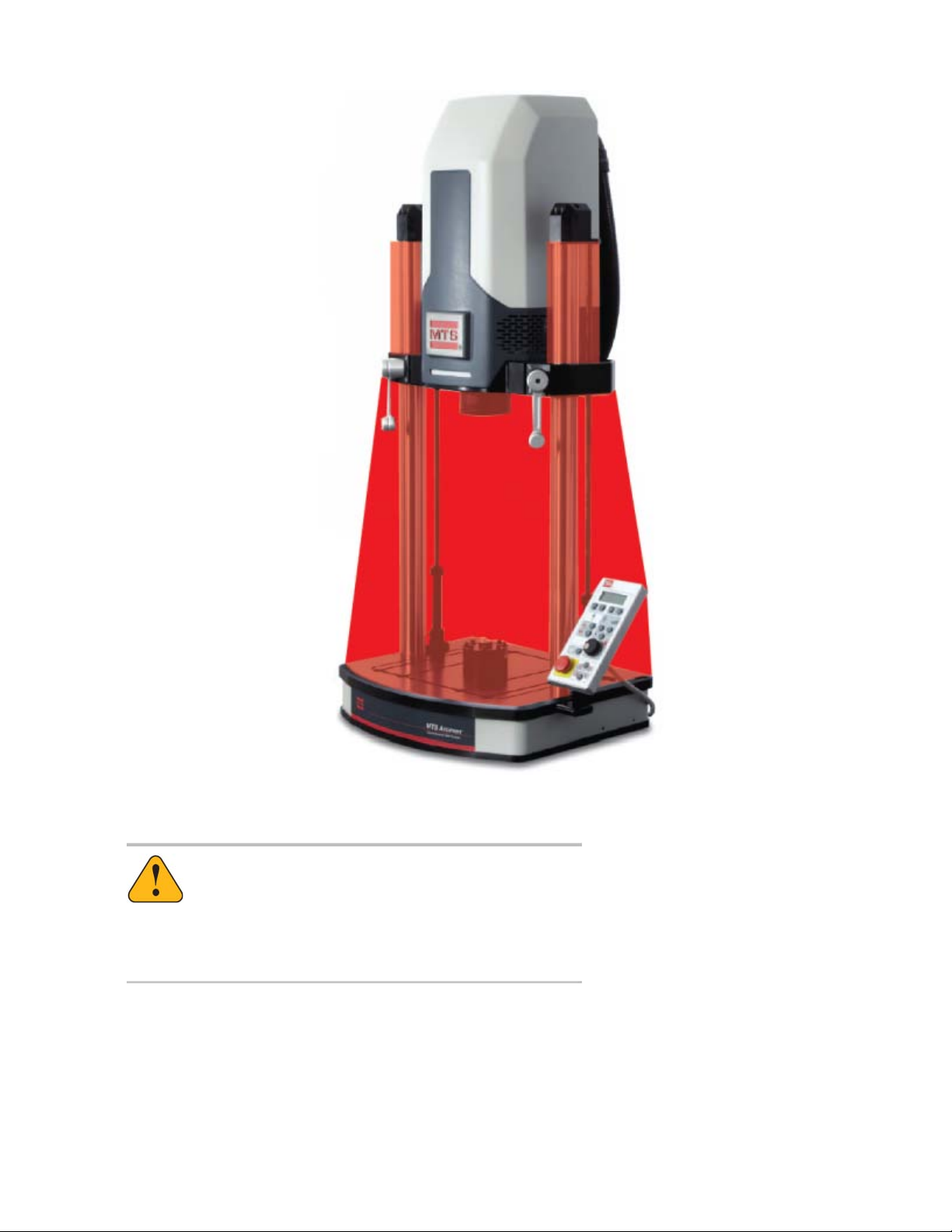
Crush Zone
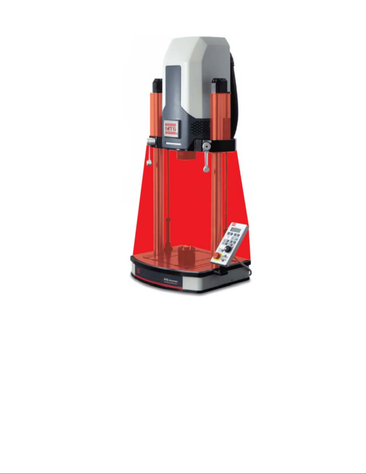
A crush zone exists between the T-slot base and crosshead which is highlighted in red in the following figure.
Keep clear of this area when the actuator is in motion. Press the Emergency Stop button on the frame-mounted
control to shut off power to the motor and stop actuator motion.
MTS Acumen™ Electrodynamic Test System 19
Page 20
Safety
Crush Zone of an MTS Acumen System
Warning:
Applying power can result in sudden actuator motion.
A moving actuator can injure anyone in its path.
Always clear the actuator area before applying power.
20 MTS Acumen™ Electrodynamic Test System
Page 21
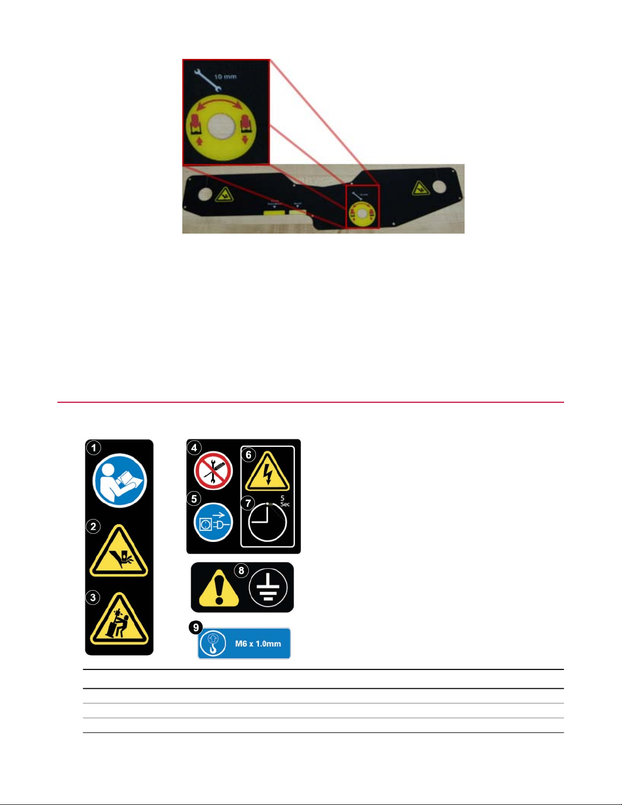
Crosshead Emergency Operation
The load frame has a manual lift actuation feature. It consists of manual method to turn the lift drive system
if the load frame or lift system lose power. In such an event, an external 10mm hex bolt can be accessed
from the underside of the crosshead. A 10mm socket wrench is required to actuate the lift system. The label
shows which direction to turn the wrench to either raise or lower the crosshead.
There are several scenarios in which the manual lift actuation system would be useful.
• In the event of a loss of facility power, a specimen can be removed from the system.
• If there is a system malfunction that prevents running the lifts via typical electrical means, the manual
approach can be used to remove specimens.
• In the event of a user, tool, fixture or specimen becoming entrapped in the load frame, and power is
removed either via E-stop activation, power switch activation or power cord removal, the entrapped person
or tool can be removed using the manual mechanism.
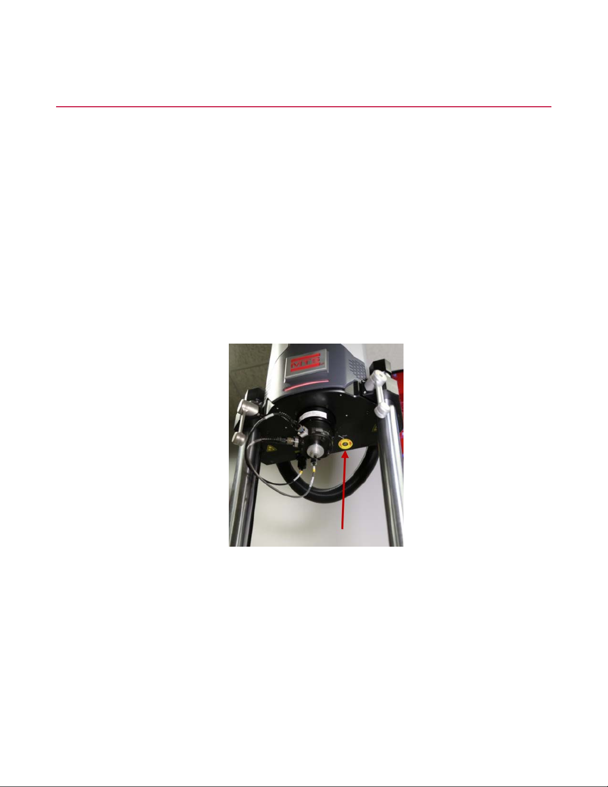
The following figure shows a close-up of the system load cell mounted on the actuator and a red arrow pointing
to the location of the hex bolt.
Safety
The manual locks must be unlocked for the system to move the crosshead.
Location of Manual Crosshead Adjustment in Relationship to Actuator Rod
MTS Acumen™ Electrodynamic Test System 21
Page 22
Safety
Location of Hex Bolt on Bottom of Crosshead
To adjust the crosshead manually:
1. Turn the left and right crosshead locks into the fully unlocked position.
2. Using a 10 mm socket wrench, turn the manual crosshead adjustment hex bolt counter-clockwise to raise
the crosshead, and turn it clockwise to lower the crosshead.
Hazard Icons
Following are the typical hazard icons used on MTS Acumen load frames.
DescriptionItem
Read manuals.1
Crush point.2
Tipping hazard.3
22 MTS Acumen™ Electrodynamic Test System
Page 23

Safety
DescriptionItem
No user-serviceable parts.4
Disconnect power before service.5
Electrical shock hazard.6
7
Electrical shock timer; value indicates number of seconds electrical shock hazard exists
after system power is disconnected.
Redundant protective earth ground connection required. Consult manual for instructions.8
Lift hole with thread size.9
MTS Acumen™ Electrodynamic Test System 23
Page 24

Page 25

Introduction
Topics:
•
Purpose .................................................................................................................................................26
•
Load Frame Dimensions........................................................................................................................29
MTS Acumen™ Electrodynamic Test System 25
Page 26

Introduction
Purpose
The purpose of this manual is to help you understand your load frame, its capabilities, and operating
requirements. This manual provides information for both MTS Acumen Electrodynamic Test Systems: 1.25 kN
and 3.0 kN. Read each section carefully and refer to the manual whenever you need assistance.
Intended Use
MTS Acumen systems provide highly precise load and motion control to accommodate a broad spectrum of
testing needs such as:
• Static and dynamic testing of polymers, composites, and other materials
• Biomaterials and medical device components
Inappropriate Use
Before you attempt to use the MTS Acumen Electrodynamic Test System, read and understand this manual.
Improper installation or operation of this product can result in hazardous conditions that can cause severe
personal injury or death, and damage your equipment and specimen.
Description
The MTS Acumen system provides a conventional load frame design with a powered, movable crosshead
and manual crosshead locks. The T-slot table provides flexibility for fixture mounting. The quick-change load
cell design simplifies attaching accessories.
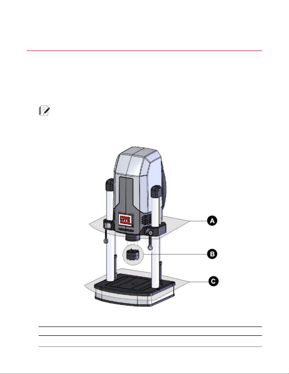
Load Frame Components
The following figure shows the components of the two-column load frame.
26 MTS Acumen™ Electrodynamic Test System
Page 27

Introduction
Two-Column Load Frame
Two-Column Load Frame Description
DescriptionItem
Actuator and power electronics (behind hood).1
Columns on which the crosshead moves up and down.2
Actuator rod.3
Manual crosshead locks. Crosshead locks must be in a fully locked position to run a test.4
Frame-mounted control.5
T-slot base plate.6
Load cell mounted on table top (load cell can also be mounted on the actuator).7
Crosshead lift.8
9
Frame-mounted status light allows you to view system status at a glance. This status is
coordinated with the MP software System panel. Status is indicated by the following colors
and a blinking or solid light:
AC power to the frame is off.Unlit
Interlocked.Red (Solid)
MTS Acumen™ Electrodynamic Test System 27
Page 28

Introduction
DescriptionItem
Red or White (Flashing)
System is in service mode. To move the system out of service
mode, slide the Service Mode switch on the upper back of
the system, and click Interlock Reset. If problems continue,
contact MTS Technical Support.
Interlock cleared, standby power is on.White (Solid)
Interlock cleared, low power.Blue (Flashing)
Interlock cleared, high power, not running.Blue (Solid)
Interlock cleared, running state.Green (Solid)
Interlock cleared, temperature warning.Yellow (Solid)
Note:
The fans to cool the electric motor increase in speed
with increasing temperature and will become louder.
This is normal system operation, and it is not necessary
to shut down the system. Reducing the frequency
and/or force output of the system will allow the actuator
to cool down. The system status light will remain yellow
until the actuator has cooled down. If the electric motor
becomes too hot, power to the electric motor will be
28 MTS Acumen™ Electrodynamic Test System
Page 29

DescriptionItem
Load Frame Dimensions
Note:
Specifications subject to change without notice.
Introduction
automatically turned off in order to prevent damage to
the system.
MTS Acumen™ Electrodynamic Test System 29
Page 30

Introduction
Load Frame Specifications
MTS Acumen 3MTS Acumen 1DescriptionDimension
A
A
B
F
G
H
3
4
5
6
1
2
MTS Acumen Load Frame Weight
Note:
Specifications subject to change without notice.
26 mm (1.02 in)26 mm (1.02 in)Minimum test space height
819 mm (32.24 in)603 mm (23.74 in)Maximum test space height
133 mm (5.24 in)133 mm (5.24 in)Working height
460 mm (18.11 in)375 mm (14.75 in)Test space widthC
63.5 mm (2.5 in)63.5 mm (2.5 in)Column diameterD
634 mm (24.96 in)550 mm (21.65 in)Footprint widthE
501 mm (19.82 in)485 mm (19.09 in)Footprint depth
764 mm (30.08 in)679 mm (26.73 in)Overall width
1726 mm (67.95 in)1511 mm (59.49 in)Overall height
Load Frame Weight
Weight
159 kg (350 lb)MTS Acumen 1
188 kg (415 lb)MTS Acumen 3
MTS Acumen Electrical Requirements
Note:
Specifications subject to change without notice.
1
Assumes standard system load cell installed, crosshead fully lowered, and actuator fully extended to end of
the dynamic stroke.
2
Assumes standard system load cell installed, crosshead fully raised, and actuator fully retracted to end of the
dynamic stroke.
3
From table to top of work surface, without optional isolation pads.
4
For systems with optional test area enclosure, add 98 mm (3.8 in) for overall system dimensions.
5
For systems with optional test area enclosure, add 45 mm (1.8 in) for overall system dimensions.
6
Measured with crosshead fully raised, without optional isolation pads.
30 MTS Acumen™ Electrodynamic Test System
Page 31

Introduction
Electrical connections must be made by qualified personnel and conform to local codes and regulations.
Local electrical codes supersede any information found here.
MTS Acumen 3MTS Acumen 1Electrical Requirements
200-240 VAC100-120 VAC (200-240)Voltage
50-60 Hz50-60 HzFrequency
7
MTS Acumen Force Ratings
Note:
Specifications subject to change without notice.
8
9
10
10 Amp7 (4) AmpCurrent
SingleSinglePhase
Force Ratings
MTS Acumen 3MTS Acumen 1Specification
3000 N (670 lbf)1250 N (280 lbf)Dynamic force
2000 N (450 lbf)850 N (190 lbf)Static force
70 mm (2.76 in)70 mm (2.76 in)Actuator dynamic stroke
>100 Hz>100 HzDynamic performance
7
MTS Acumen 1 current rated at 100 VAC. MTS Acumen 3 current rated at 200 VAC.
8
Verifiable with MTS compression spring test. Performance may vary depending on test type, test setup,
frequency, specimen, environment, and other factors.
9
Verifiable with MTS compression spring test. Performance may vary depending on test type, test setup,
frequency, specimen, environment, and other factors.
10
+/- 35 mm
MTS Acumen™ Electrodynamic Test System 31
Page 32

Introduction
Note:The specifications above are for 25°C (75°F) ambient temperature.
MTS Acumen Noise Level
Note:
Specifications subject to change without notice.
Noise Level
MTS Acumen 3MTS Acumen 1Noise Level
11
12
47 dbA47 dbATypical
69 dbA69 dbAMaximum
11
Typical usage at 1 m, free field. Noise level varies depending upon test type, specimen, environment, and
other factors.
12
Typical usage at 1 m, free field. Noise level varies depending upon test type, specimen, environment, and
other factors.
32 MTS Acumen™ Electrodynamic Test System
Page 33

Installation
Topics:
•
Frame Location and Ventilation.............................................................................................................34
•
Environmental Requirements................................................................................................................34
•
Interlock Logic........................................................................................................................................35
•
Load Frame Connections......................................................................................................................35
•
Accessory Mounting Dimensions...........................................................................................................42
MTS Acumen™ Electrodynamic Test System 33
Page 34

Installation
Frame Location and Ventilation
To ensure proper ventilation, locate the load frame approximately 300 mm (12 inches) from adjacent walls
and equipment. Allow approximately 1 m (3 feet) behind the equipment for service access. Do not block the
vent holes on the sides or back of the frame.
For comfortable working conditions and proper equipment operation, heat dissipation of the equipment must
be considered in providing adequate heating or air conditioning in the laboratory area. Heat dissipation can
be approximated by summing the heat losses going into a room (1 kVA is equivalent to 860 kcal/hr [3,400
Btu/hr]) and the gains from other sources such as furnaces and personnel.
Environmental Requirements
All MTS Acumen load frames are intended for indoor use only. This indoor environment must conform to the
following environmental specifications.
13
Environmental Requirements
SpecificationParameter
5° to 40° C (41° to 104° F)Operating Temperature
5 to 85% Non-condensingOperating Humidity
-18° to 49° C (0° to 120° F)Storage Temperature
90% Non-condensingMaximum Storage Humidity
2000 m (6562 ft)Maximum Altitude
2Pollution Degree
IP20IP Rating
IIOvervoltage Category
13
Take care when using heat producing accessories, such as ovens. Emitted heat from such devices may
damage the MTS Acumen if not properly controlled.
34 MTS Acumen™ Electrodynamic Test System
Page 35
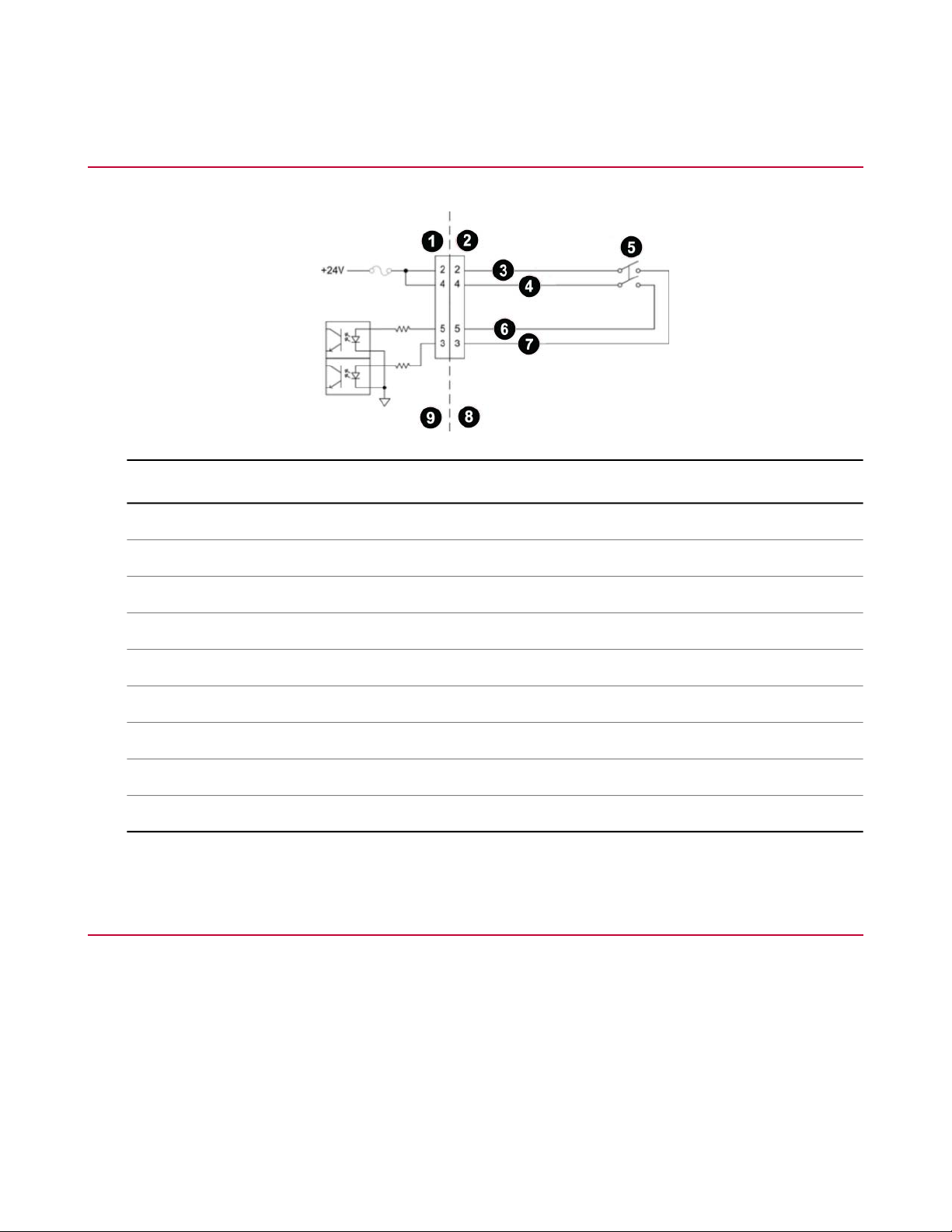
Interlock Logic
DescriptionItem
Installation
D9S1
D9P2
(Safety A+)3
(Safety B+)4
Custom Test Area Enclosure Switch5
(Safety B)6
(Safety A)7
Test Area Enclosure8
MTS Acumen Frame9
Load Frame Connections
Connecting the Main Power
The input voltage of MTS Acumen 1 frame is single phase 100-120 V /200-240 V, 50-60 Hz.
The input voltage of MTS Acumen 3 frame is single phase 200-240 V, 50-60 Hz.
MTS Acumen™ Electrodynamic Test System 35
Page 36
Installation
Note:
Local electrical codes supercede any information found here.
Customers should use the power cord kit supplied by MTS for connecting electrical power and ground to the
load frame. Use of power cords with inadequate ratings that are not equivalent to the power cord provided
with your MTS Acumen product could cause a dangerous situation.
Note:
Electrical connections must be made by qualified personnel and is their responsibility for using the
proper power disconnect that conforms to local codes and regulations when connecting the machine
to the buildings main power.
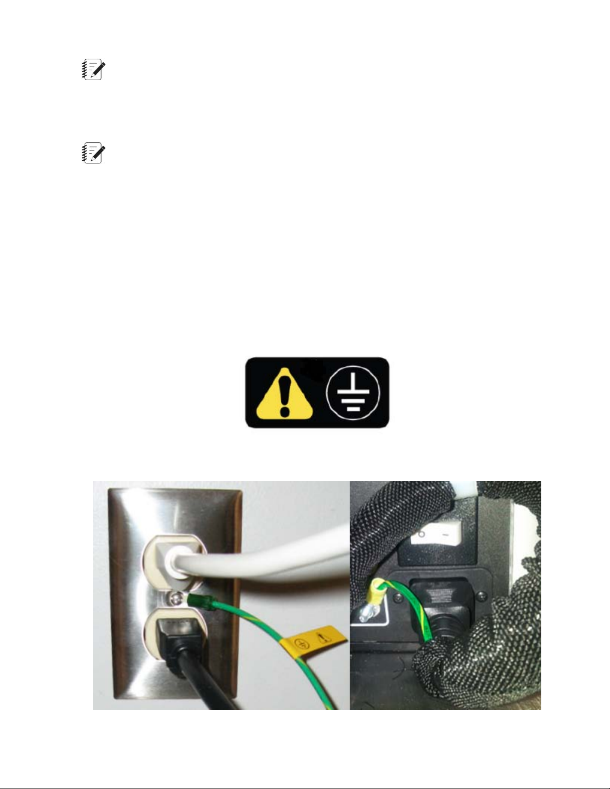
Redundant Protective Earth Ground Connection
A redundant protective earth ground connection is required. MTS Acumen Systems contain high-power drive
systems which create high ground-leakage current; therefore the MTS Acumen load frame requires a permanent
protective earth ground connection in addition to the ground in the AC mains plug/socket connection. An
additional protective earth conductor of appropriate wire gage is supplied with the power cord for this product. At
the load frame, this protective earth conductor must be connected to the grounding post near the AC mains
input of the MTS Acumen load frame. Facility-side connection of the protective earth conductor must be done
in accordance with local electrical codes. If a supplemental ground is not available, MTS offers an optional
permanently wired hard cord kit.
The photos below show the Mains Power Cable with the Supplemental Ground connection.
36 MTS Acumen™ Electrodynamic Test System
Page 37

Electrical Disconnect
Ensure that there is access and adequate room behind the frame to allow electrical disconnection of the
power cord. Disconnect the power cord before cleaning or inspecting any part of the test frame.
When the hard cord kit option is used, the customer is responsible for providing an electrical power disconnect
that is easy to operate and easy to reach. It must also meet IEC 60947-1 and IEC 60947-3 standards.
Recommended circuit breakers would be ones that are of the thermal-magnetic type with characteristics
suitable for large inductive loads (D-type trip characteristic). If fuses are used, it is recommended that they
are of the time-delay type with dual elements. These recommendations should be followed to avoid nuisance
tripping.
Installing Cables
Exercise care when connecting cables. Ensure that you use the correct cables and that all connections are
secure. When you are finished, double-check to ensure that all components are connected properly.
To maintain EMC compliance and help ensure optimal performance, MTS recommends ordering all system
cables from MTS. Cables should be installed so that they are protected from conditions that could damage
the cable.
Installation
Caution:
There is dangerous voltage inside the machine.
Connecting cables with power applied can cause damage to the equipment.
Ensure that the power is turned off before connecting cables.
Back Panel Connectors
NameItem
1
Force Transducer
14
494.26 Force2
3
14
For use when the transducer is mounted to the T-Slot base.
15
For use when the transducer is mounted to the T-Slot base.
Accelerometer
494.26 Accel4
15
MTS Acumen™ Electrodynamic Test System 37
Page 38

Installation
NameItem
494.26 Position 25
494.27 Position 16
494.27 Frame Status7
Grips8
D/A Act. Cmd.9
J23 Prog. Status10
J29 Frame Interlocks11
Frame Control12
494.47 Frame Control13
Enclosure Switch14
J28 Actuator Enable15
J43 Interlock Status16
Remote E-Stop17
Grounding Information
All equipment related to the load frame should be connected to the same electrical circuit if possible. If the
computer, monitor, or other peripherals are connected to a different electrical circuit (for example, the load
frame is connected to 208 VAC power but the computer and monitor are connected to 120 VAC power), make
sure there is no voltage difference between the two different grounds. If voltage is present, damage could
occur to the electronics in the machine, the computer and monitor, or the peripherals being used. This must
be resolved before turning on the equipment.
Where electrical power is of poor quality (noise spikes, poorly regulated, and so forth) or the ground system
in the facility contains electrical noise, attach a 4 AWG wire directly to a good earth ground point, such as a
2 m (6 ft) copper grounding rod driven at least 2 m (6 ft) into the ground. Grounding must conform to local
electrical codes.
Connector Pinouts
Force Transducer (D15S)
SignalPin
EX+1
EX-2
No Contact3
38 MTS Acumen™ Electrodynamic Test System
Page 39

Installation
SignalPin
FB+4
FB-5
No Contact6
Shield7
TEDS data8
No Contact9
EXS+10
No Contact11
RCAL1 (FBR+)12
RCAL2 (FBR-)13
TEDS ground14
EXS-15
Remote E-Stop (D15S)
SignalPin
ESTOPB_OUT-1
No Contact2
ESTOP_OUT_MONITOR-3
ESTOP_OUT_MONITOR+4
ESTOPB_IN+5
ESTOPA_OUT-6
ESTOPB_IN-7
ESTOPA_IN+8
ESTOPA_IN+9
No Contact10
No Contact11
No Contact12
ESTOPA_IN-13
MTS Acumen™ Electrodynamic Test System 39
Page 40

Installation
SignalPin
ESTOPA_OUT+14
No Contact15
Note:If E-STOP_OUT is not used, pins 3 and 4 must be jumpered together.
Accelerometer (D9S)
SignalPin
FB+1
FB-2
No Contact3
No Contact4
No Contact5
No Contact6
No Contact7
EX+8
EX-9
Enclosure Switch (D9S)
SignalPin
GUARD_VCC1
GUARDA+2
GUARDA3
GUARDB+4
GUARDB5
No Contact6
GUARD_GND7
No Contact8
No Contact9
40 MTS Acumen™ Electrodynamic Test System
Page 41

System Load Cell Mounting
The System Load Cell has two mounting configurations. One option is the top mount configuration, in which
the System Load Cell is bolted to the Acumen Linear Actuator. The other option is the bottom mount
configuration, in which the System Load Cell is bolted to the Acumen Frame Base.
The cable connections for System Load Cell are determined by its physical mounting on the Acumen Frame.
If the System Load Cell is mounted to the actuator (top mount), the connections are on the crosshead. If the
load cell/accelerometer is mounted to the frame base (bottom mount), the connections are on the lower panel.
Installation
If theSystem Load Cell is mounted to the frame base (bottom mount), the connections are shown in the
graphic below.
Connect theSystem Load Cell to either the top crosshead connector, or bottom lower panel connector, but
not both.
MTS Acumen™ Electrodynamic Test System 41
Page 42
Installation
Accessory Mounting Dimensions
You can attach numerous testing accessories and fixtures to the load frame for specialized tests. The following
figures show the standard mounting holes in each style of load frame. Use these standard mounting holes
to mount your accessories. Do not drill or tap new holes that may weaken or otherwise compromise the
integrity of the load frame.
The following sections describe each style of load frame. Some dimensions are the same for all MTS Acumen
models, and are only listed once. Look for the section pertaining to your specific model for the appropriate
dimensions.
Note:Unless otherwise specified, the tolerance for all dimensions is ±0.254 mm (0.010 in).
MTS Acumen Accessory Overview
The following graphic shows the locations of the different mounting options.
MTS Acumen Accessory Overview
DimensionItem
Actuator Fixture MountingA
42 MTS Acumen™ Electrodynamic Test System
Page 43

DimensionItem
Loadcell Fixture MountingB
Baseplate Fixture MountingC
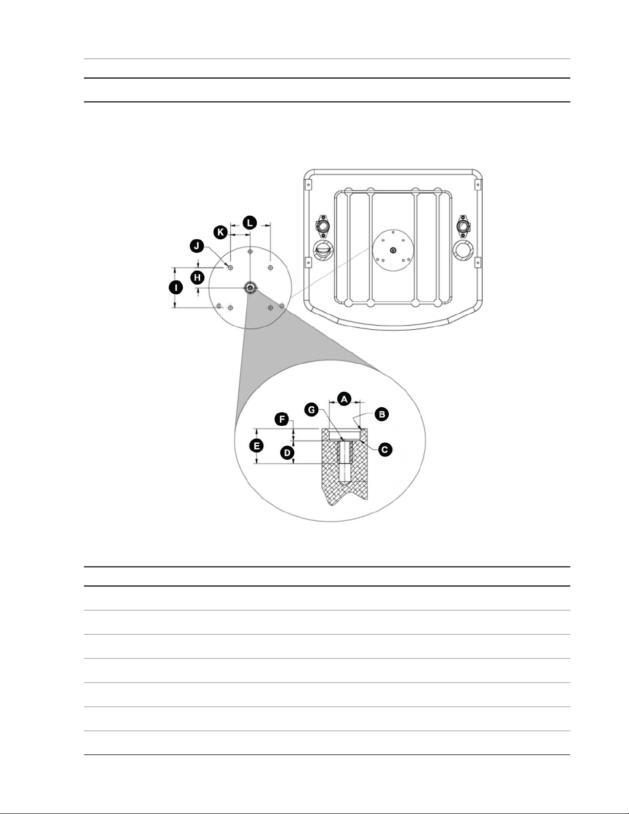
Actuator Fixture Mounting Dimensions
This section provides dimensions for mounting fixtures to the actuator.
Installation
Actuator Fixture Mounting Dimensions
DimensionItem
16.012 mm +0.0254 mm -.0000 (0.6304 in diameter +0.0010 in -0.0000 in)A
1.52 mm (0.060 in x 45°)B
R. 0.76 mm (R. 0.030 in) MaximumC
11.98 mm (0.472 in) Thread depthD
18.33 mm (0.722 in) Total depthE
6.35 mm (0.250 in)F
M6 X 1.0 mm -6H 11.98 mm deep (0.472 in deep)G
31.41 mm (1.237 in) Two placesH
62.86 mm (2.475 in) Two placesI
MTS Acumen™ Electrodynamic Test System 43
Page 44

Installation
DimensionItem
M6 X 1.0 mm -6H 11.98 mm deep (0.472 deep) Four placesJ
31.41 mm (1.237 in) Two placesK
62.86 mm (2.475 in) Two placesL
Loadcell Fixture Mounting Dimensions
This section defines the loadcell's fixturing interface. The system loadcell can be mounted to either the
baseplate, or the crosshead. The graphic in this section and the sections above show the loadcell mounted
to the crosshead.
Loadcell Fixture Mounting Dimensions
DimensionItem
16.012 mm +0.0254 mm -.00000 mm (0.6304 in +0.0010 -0.0000 in)A
1.54 mm (0.060 in) x 45°B
R. 0.76 mm (R. 0.030 in) MaximumC
11.98 mm (.472 in) Thread depthD
18.33 mm (0.722 in) Total depthE
6.35 mm (0.250 in)F
M6 X 1.0 mm -6H 11.98 mm deep (0.472 in deep)G
25.14 mm (0.99 in)H
Keep fixturing below this lineI
3.81 mm (0.15 in)J
44 MTS Acumen™ Electrodynamic Test System
Page 45
DimensionItem
32.25 mm +0.000 mm -0.0254 mm (1.270 in +0.000 -0.001 in)K
Baseplate Fixture Mounting Dimensions
This section provides dimensions for mounting fixtures to the baseplate.
Installation
Baseplate Fixture Mounting Dimensions
DimensionItem
ø 16.012 mm +0.0254 mm -0.0000 mm (ø 0.6304 in +0.0010 in -0.0000 in)A
1.52 mm (0.060 in x 45°)B
0.76 mm (R.0.030 in)C
11.98 mm (0.472 in) Thread depthD
18.33 mm (0.722 in) Total depthE
6.35 mm (0.250 in)F
M6 X 1.0 mm -6H 11.98 mm deep (0.472 in deep)G
MTS Acumen™ Electrodynamic Test System 45
Page 46
Installation
DimensionItem
31.41 mm (1.237 in) Two placesH
62.86 mm (2.475 in) Two placesI
M 6X 1.0 mm -6H 11.98 mm deep (0.472 in deep) Four placesJ
31.41 mm (1.237 in) Two placesK
62.86 mm (2.475 in) Two placesL
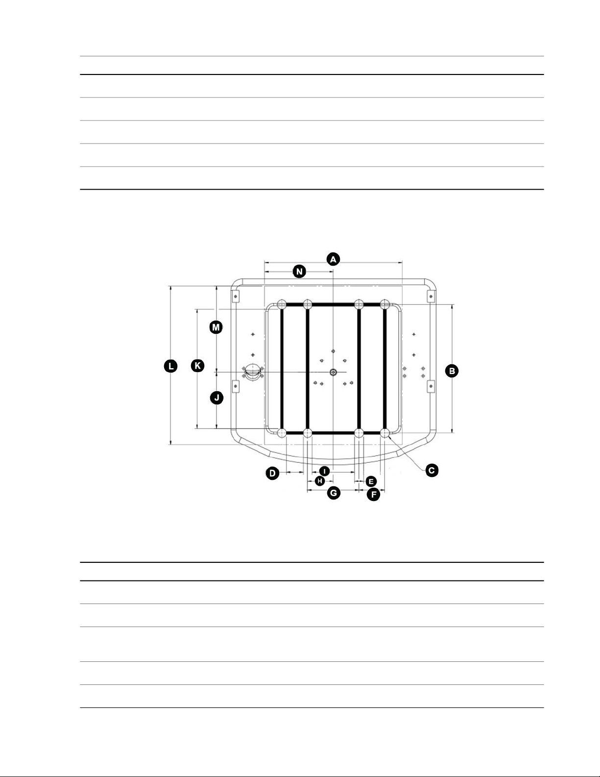
MTS Acumen 1 Baseplate and T-slot
This section provides dimensions for mounting accessories to the MTS Acumen 1 baseplate and T-slot.
MTS Acumen 1 Baseplate and T-slot
MTS Acumen 1 Baseplate and T-slot Dimensions
DimensionItem
374 mm (14.75 in) Usable areaA
349 mm (13.75 in)B
C
46 MTS Acumen™ Electrodynamic Test System
25.4 mm diameter X 16.5 mm deep (1.00 in diameter X 0.65 in deep) Eight
places
45.9 mm (1.81 in) Two placesD
24.1 mm (0.95 in) TypicalE
Page 47
DimensionItem
70.0 mm (2.756 in) Two placesF
140.0 mm (5.51 in)G
70.0 mm (2.756 in)H
116.0 mm (4.57 in)I
153.1 mm (6.03 in)J
325.1 mm (12.80 in)K
431.8 mm (17.00 in) Usable areaL
234.9 mm (9.25 in) Usable areaM
187.3 mm (7.37 in) Usable areaN
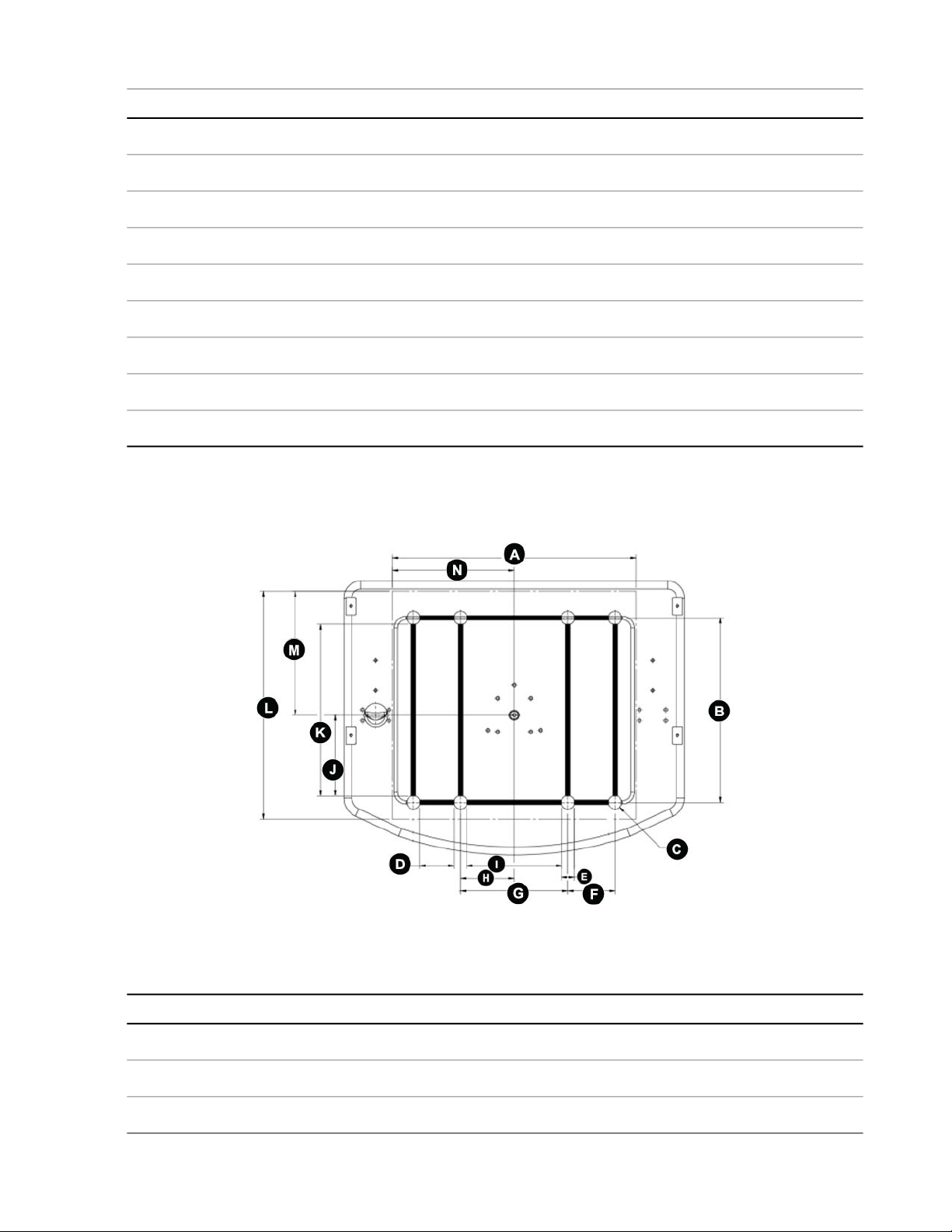
MTS Acumen 3 Baseplate and T-slot
Installation
This section provides dimensions for mounting accessories to the MTS Acumen 3 baseplate and T-slot.
MTS Acumen 3 Baseplate and T-slot
MTS Acumen 3 Baseplate and T-slot Dimensions
DimensionItem
459 mm (18.10 in) Usable AreaA
349 mm (13.75 in)B
25.4 mm diameter X 16.5 mm deep (1.00 in diameter X 0.65 in deep) Eight placesC
MTS Acumen™ Electrodynamic Test System 47
Page 48

Installation
DimensionItem
64.7 mm (2.55 in) Two placesD
24.1 mm (0.95 in) TypicalE
88.9 mm (3.5 in) Two placesF
203.2 mm (8.00 in)G
101.6 mm (4.00 in)H
179.0 mm (7.05 in)I
153.1 mm (6.03 in)J
325.1 mm (12.80 in)K
431.8 mm (17.00 in)L
234.9 mm (9.25 in)M
229.8 mm (9.05 in)N
MTS Acumen T-slot
This section provides dimensions for the T-slot.
MTS Acumen T-slot (Scaled cross-section view)
MTS Acumen T-slot Dimensions
DimensionItem
8.255 mm (0.325 in)A
48 MTS Acumen™ Electrodynamic Test System
Page 49

DimensionItem
9.017 mm (0.355 in)B
16.51 mm (0.650 in)C
14.986 mm (0.590 in)D
7.493 mm (0.295 in)E
R 0.9906 mm (R.039 in)F
R 0.6096 mm (R.024 in)G
0.012 x 45°H
4.1402 mm (0.163 in)I
DIN 508 Extended T-slot nut
This section provides dimensions for the recommended T-slot nut.
Installation
DIN 508 Extended (Recommended T-slot Nut)
DIN 508 Extended (Recommended T-slot Nut) Sizes
DimensionItem
M6 x 1.0- 6HA
19.05 mm (0.75 in) Minimum lengthB
9.398 mm (0.37 in)C
MTS Acumen™ Electrodynamic Test System 49
Page 50

Installation
DimensionItem
8.001 mm (0.315 in)D
10.0076 mm (0.394 in)E
5.9944 mm (0.236 in)F
13.9954 mm (0.551 in)G
7.0104 mm (0.276 in)H
0.015 x 45° TypicalI
3.9878 mm (0.157 in)J
50 MTS Acumen™ Electrodynamic Test System
Page 51

Operation
Topics:
•
Operation...............................................................................................................................................52
MTS Acumen™ Electrodynamic Test System 51
Page 52

Operation
Operation
This section describes the actions performed during normal, day-to-day operation of the MTS Acumen frame.
For information on using the MTS Acumen frame in actual testing, refer to the testing software manual.
Warning:
There are moving parts inside the machine.
Operating the machine without covers in place can expose the operator to moving parts that
could cause injury if contact is made.
Do not operate the MTS Acumen test frame without the covers in place.
Warning:
There are potential hazards during material testing.
Hazards generated by the materials during testing can cause injury or death.
Ensure that only qualified, trained personnel be allowed to operate the machine. Keep bystanders
away during machine operation.
Main Power Switch (I/O) and Emergency Stop
Main Power Switch (I/O)
Controller Power
The main power switch for the controller is located on the back of the controller unit. Press position I to turn
the power on to the controller. Press position O to turn off power to the controller.
FlexTest Controller Power Switch
Load Frame Power
The main power switch for the MTS Acumen load frame is located on the back side of the load frame base.
Press position I to turn the power on to the load frame. When the power is on, the frame-mounted status light
on the front of the hood illuminates. Press position O to turn off power to the load frame.
52 MTS Acumen™ Electrodynamic Test System
Page 53

Operation
Load Frame Power Switch
Note:
In case of emergency, power can also be removed from the frame or controller by removing the
detachable power cord.
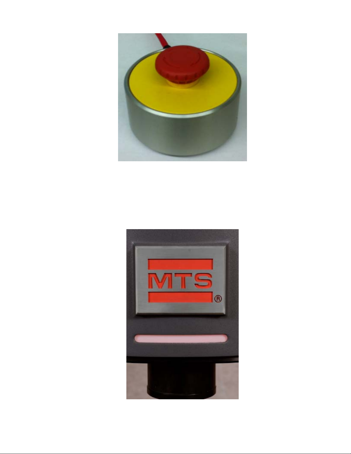
Emergency Stop Button
The frame-mounted control is equipped with an Emergency Stop button to be used for emergency purposes
only. There is also an optional Remote Emergency Stop button. The Emergency Stop buttons will shut off
power to the main actuator and crosshead lift system. To release an activated button, turn it clockwise.
The Emergency Stop button should be periodically tested by pressing it when the controller is powered on,
but not when a test is running. The controller continuously monitors the redundant Emergency Stop chain
and will generate an interlock alerting the user if any problems are detected. Pressing the Emergency Stop
button allows the active state to be checked.
Frame-Mounted Control Emergency Stop Button
MTS Acumen™ Electrodynamic Test System 53
Page 54
Operation
Optional Remote Emergency Stop Button
Frame-Mounted Status Light
The frame mounted status light allows you to view system status at a glance. This status is coordinated with
the MP software System panel. Status is indicated by the following colors and a blinking or solid light:
54 MTS Acumen™ Electrodynamic Test System
Page 55

Crush Zone Hazards
Operation
DescriptionLED Color
AC power to the frame is off.Unlit - Solid
Interlocked.Red - Solid
Service mode. Contact MTS Technical Support.Red / White - Flashing
Interlock cleared, standby power is on.White - Solid
Interlock cleared, low power.Blue - Blinking
Interlock cleared, high power, not running.Blue - Solid
Interlock cleared, temperature warning.Yellow - Solid
Interlock cleared, running state.Green - Solid
It is important to stay clear of any potential crush zones when the system is operating. Know where the crush
zones are in your system and protect yourself and others from those crush zones with appropriate safety
devices. The following paragraphs describe crush zones and precautions to take while working around crush
zones.
Locations
A crush zone exists between the T-slot base and crosshead.
MTS Acumen™ Electrodynamic Test System 55
Page 56
Operation
Precautions
Keep clear of any mechanical linkage that moves within a closed area. If the linkage should move (when the
system starts or due to mechanical failure), very high forces can be present that could pinch, cut, or crush
anything in the path of linkage movement.
Never allow any part of your body to enter the path of machine movement or to touch moving machinery,
linkages, hoses, cables, specimens, and so forth. These present serious crush points or pinch points.
Fixture Mounting
MTS offers a wide variety of fixtures. Mounting these fixtures typically involves installing the fixture or load
cell onto a mounting (clevis pin) adapter and securing it with a mounting dowel (pin). To further secure a
fixture, some configurations also include locking collars.
56 MTS Acumen™ Electrodynamic Test System
Page 57
Frame-Mounted Control
The frame-mounted control can be attached to the left or right side of the frame. It provides controls to help
you mount fixtures, and install specimens. The frame-mounted control also has an alphanumeric display and
illuminated icons to provide feedback.
Note:
When exclusive control is provided by the frame-mounted control, the actuator controls on the MP
application will be locked and overlaid by the frame-mounted control exclusive control icon:
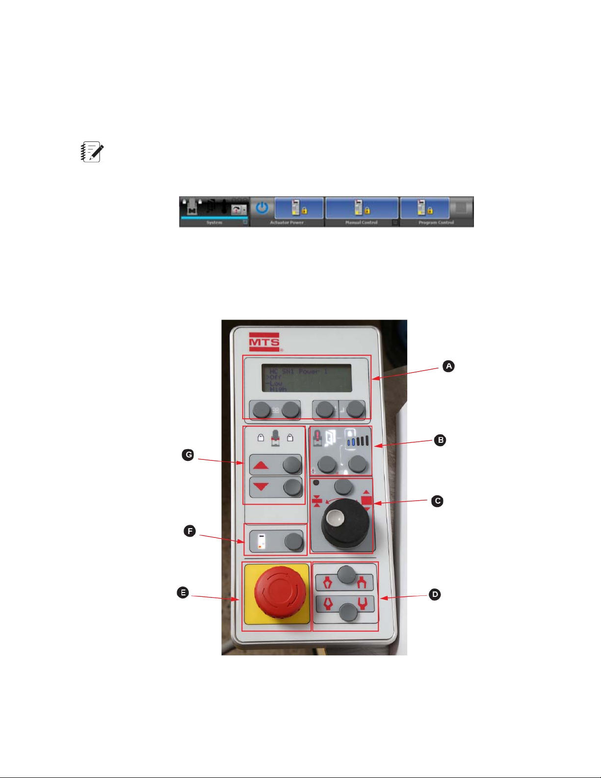
The following figure separates the frame-mounted control into boxed sections that are described in the table
that follows.
Operation
Frame-Mounted Control
MTS Acumen™ Electrodynamic Test System 57
Page 58

Operation
Frame-Mounted Control Description
DescriptionControlsSection
Display and display controlsA
1 Display. Shows four lines. There is a screen
for Manual Command (MC), Auto Offset (AO),
and a screen to change the power level. When
the interlock reset/override button is pressed, the
screen shows the override count-down, and you
can press the Enter button to cancel the override.
2, 3 Page forward or page back. Shows next
or previous text in the display.
4 Scroll. Scrolls down the text display. Selection
cycles to the top when the bottom line is
highlighted and you press the button.
5 Enter. Executes the highlighted command in
the display (for example, selecting Low and hitting
Enter would apply low power).
B
Indicators and controls related to actuator
power and control
1 Controller or program interlock indicator.
When illuminated, an interlock has occurred. On
the MTS TestSuite software, hover your cursor
over the red system error icon in the Status panel
for the cause of the interlock, or click the open
window icon to view all status indicators.
2 Door Open (only active with optional test area
enclosure). When illuminated, the door to the test
area enclosure is open, High-Speed Prohibit is
activated, and the system is in High-Speed
Prohibit mode (see High-Speed Prohibit Mode).
When the door is closed, the door indicator is not
visible.
3 High-Speed Prohibit indicator. When
illuminated, High-Speed Prohibit has been
activated by pressing the High-Speed Prohibit
button (see 6). If an optional test area enclosure
is present, High-Speed Prohibit is activated and
the indicator illuminates when the door is open
(see 2).
4 Power Indicator. Two bars = Low Power, Five
bars = High Power.
58 MTS Acumen™ Electrodynamic Test System
5 Button to reset interlocks and override them
temporarily (30 seconds). Each time you press
the button, another 30 seconds is added to the
override time which gets shown on the display
(see 1).
Page 59

Operation
DescriptionControlsSection
Important:
When you press this button, all limits are
overridden.
6 High-Speed Prohibit button. Press to put the
system in High-Speed Prohibit mode (see
High-Speed Prohibit Mode) and to prevent the
actuator from going into the Power High state.
C
D
Manual actuator control toggle button and
rotary dial
1 Manual Actuator Control Indicator. When
illuminated, manual control of the actuator is
active, and you can adjust the actuator using the
Actuator Control Dial (3).
2 Actuator Control Enable button. Press to
enable actuator positioning using the rotary dial;
press again to disable actuator positioning using
the rotary dial. Illumination of indicator (1) signifies
that the actuator control is enabled.
3 Actuator Control Dial. Turn clockwise to move
actuator in tension (retract) direction. Turn counter
clockwise to move actuator in compression
(extension) direction. The control dial operates
in the active control mode.
Grip control toggle buttons (work only with
optional, external pneumatic grip supply)
1 Upper Pneumatic Grip Control button. Press
to close the upper grip fixture; press again to open
the upper grip fixture.
2 Lower Pneumatic Grip Control button. Press
to close the lower grip fixture; press again to open
the lower grip fixture.
Emergency Stop buttonE
Press to stop the test and shut off power to the
main actuator and lift system but retain power to
the rest of the electronics in the frame. Because
power to the actuator is cut, gravity may cause
the actuator to drop. This may cause operator
harm or specimen damage, before the brake is
applied. To release emergency stop action, turn
the red button clockwise (as shown by arrows on
button).
Exclusive control toggle buttonF
Press for the frame to be managed from the
frame-mounted control only. The icon illuminates
when exclusive control is active. Press again to
MTS Acumen™ Electrodynamic Test System 59
Page 60
Operation
DescriptionControlsSection
release control from the frame-mounted control
to MTS TestSuite software.
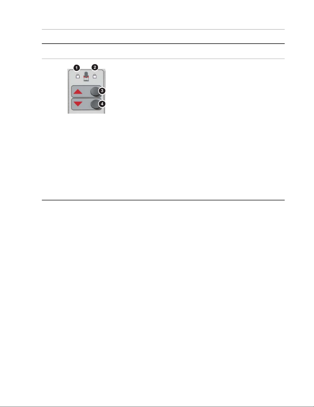
G
Crosshead manual lock indicators and
crosshead positioning buttons
1 Left crosshead manual lock icon. When
illuminated, the left crosshead manual lock handle
is in the fully locked position. When not
illuminated, the handle is in the fully unlocked
position. When blinking, the handle is in an
intermediate position.
2 Right crosshead manual lock icon. When
illuminated, the right crosshead manual lock
handle is in the fully locked position. When not
illuminated, the handle is in the fully unlocked
position. When blinking, the handle is in an
intermediate position.
3 Crosshead up button. Press to raise the
crosshead. Crosshead must be fully unlocked to
move the crosshead.
4 Crosshead down button. Press to lower the
crosshead. Crosshead must be fully unlocked to
move the crosshead.
60 MTS Acumen™ Electrodynamic Test System
Page 61

Maintenance
Topics:
•
Routine Maintenance Overview Checklist.............................................................................................62
•
General Cleaning ..................................................................................................................................64
•
Monthly Maintenance.............................................................................................................................64
•
Other Service ........................................................................................................................................64
MTS Acumen™ Electrodynamic Test System 61
Page 62

Maintenance
Routine Maintenance Overview Checklist
Important:
There are no customer serviceable components on the MTS Acumen frames. Maintenance consists
of keeping the frame and work area clean, general inspection, checking interlocks, and scheduled
frame calibration.
Recommended Service
AnnuallyMonthlyDailyCalendar Time Using 8 Hours Running
Time Rate per Day
20001608Running Time-Hours
XClean work area / Machine Surfaces
XCheck Frame Mounted Control Emergency
Stop
Present)
Applies Low Velocity
Load Frame / Crosshead
Operation
Actuator
XCheck Remote Emergency Stop (If
XCheck Test Area Enclosure - Open Door
MTSCheck Crosshead Locks For Proper
MTSCheck Crosshead Lift Belt For Wear
MTSCheck / Adjust Crosshead Lift Belt Tension
MTSCheck / Clean Crosshead Lift Screws
MTSCheck / Clean Columns
MTSAssure Crosshead Movement Is Smooth
MTSCheck Cooling System Is Operational
62 MTS Acumen™ Electrodynamic Test System
MTSClean Exposed Cooling Surfaces
MTSAssure Actuator Movement Is Smooth
MTSCheck Actuator Guidance Mechanism
MTSCheck Brake Operation
Page 63

Time Rate per Day
Electrical
Position
Maintenance
AnnuallyMonthlyDailyCalendar Time Using 8 Hours Running
MTSCheck Anti-Rotate Mechanism
MTSCheck For Excessive Contamination
MTSAssure Displacement Transducer Is Clean
MTSVerify Displacement Transducer Is Aligned
MTSConfirm Reference Transducer Is Aligned
MTSVerify Reference Transducer Center
MTSCheck Internal Cables For Abrasion
MTSCheck Internal Cable Connectors
System
Stop
Present)
Enabled
Applies Low Velocity
Power Prohibit Functions
Interlock
MTSCheck Internal Grounding
MTSClean Electronic Devices
MTSCheck Frame Mounted Control Emergency
MTSCheck Remote Emergency Stop (If
MTSCheck System Detects Velocity Limit When
MTSCheck Test Area Enclosure - Open Door
MTSCheck Frame Mounted Control - High
MTSVerify Unlocked Crosshead Generates
MTSCheck System Cable Bundle Connectors
Stable Control Modes
MTSCheck System Cable Bundle For Abrasions
MTSCheck Supplemental Ground Attached
MTSVerify Tuning Parameters Correct For
MTS Acumen™ Electrodynamic Test System 63
Page 64

Maintenance
Time Rate per Day
Correct And Enabled
AnnuallyMonthlyDailyCalendar Time Using 8 Hours Running
MTSVerify Load Frame Protection Limits
Warning:
Be careful not to spill cleaning liquid on the frame.
Cleaning solution can cause damage or injury.
To avoid hazardous conditions, always follow the manufacturers’ recommendations and cautions.
Caution:
Observe all manufacturer recommendations and cautions when using any cleaning solution.
Cleaning solution can cause damage or injury.
To avoid hazardous conditions, always follow the manufacturers’ recommendations and cautions.
General Cleaning
Clean the frame as often as needed. Use a damp, lint-free rag to clean the side covers, base, and crosshead.
If necessary, mild detergent or cleaning fluid can be used.
Monthly Maintenance
Verify that the Emergency Stop button is functioning properly.
Verify any additional interlocks are functioning properly (for example, the interlock switches on the door of a
test area enclosure).
Other Service
Regular inspection and service of the drive motor system and crosshead positioning components are needed
to prolong the life of your frame and keep it performing optimally. This type of service is preformed by MTS
field service engineers or an MTS authorized service representative. Contact your MTS authorized
representative for additional information.
64 MTS Acumen™ Electrodynamic Test System
Page 65

Maintenance
Note:
MTS offers annual maintenance and calibration plans. Contact your sales representative for more
information.
MTS Acumen™ Electrodynamic Test System 65
Page 66

Page 67

Decommissioning
Topics:
•
Decommissioning...................................................................................................................................68
MTS Acumen™ Electrodynamic Test System 67
Page 68

Decommissioning
Decommissioning
The decommissioning process is performed when the system is going to be moved or taken out of service.
Disassembly is required when performing either of these tasks.
To decommission the system:
1. Remove the specimen and fixtures. Large grips should be removed if the load frame could be tipped over.
2. Isolate the system from electrical power.
3. When the system electronics, control software, and the system PC are powered down, turn off the system’s
main electrical supply and disconnect all cables.
4. Disconnect all cables from the controller.
5. Cover the material testing machine with a dust cover, such as plastic foil. Allow for sufficient ventilation
or place a dehumidifier near the equipment.
6. Place the accessories and the instruction manual in a clean, dust-protected place, such as a tool cabinet.
Caution:
Electrical components and parts can contain hazardous chemicals and compounds.
Always refer to local codes that govern the disposal of potentially hazardous materials and
follow these codes for the proper handling and disposal of these materials.
You should follow internal safety policies for safe disposal of parts of the machine. Refer to
the MSDS for oils and greases that are used on the machine.
68 MTS Acumen™ Electrodynamic Test System
Page 69

Declarations
Topics:
•
DOC.......................................................................................................................................................70
MTS Acumen™ Electrodynamic Test System 69
Page 70
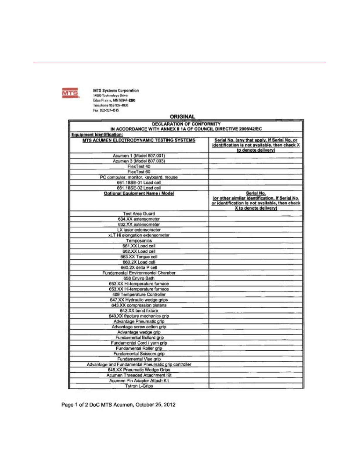
Declarations
DOC
70 MTS Acumen™ Electrodynamic Test System
Page 71

Declarations
MTS Acumen™ Electrodynamic Test System 71
Page 72

Page 73

100-265-568 B
Page 74

 Loading...