

Page 1
MTS Acumen
™
Test System Operation
100-261-657 E be certain.
Page 2

©
2014 MTS Systems Corporation. All rights reserved.
Trademark Information
MTS, FlexTest, RPC, and TestWare are registered trademarks and MTS Acumen, MTS TestSuite,
Station Builder, and Station Manager are trademarks of MTS Systems Corporation within the United
States. These trademarks may be protected in other countries. All other trademarks are the property
of their respective holders.
Proprietary Software
Software use and license is governed by the MTS End User License Agreement which defines all
rights retained by MTS and granted to the End User. All Software is proprietary, confidential, and
owned by MTS Systems Corporation and cannot be copied, reproduced, disassembled, decompiled,
reverse engineered, or distributed without express written consent of MTS.
Software Verification and Validation
MTS software is developed using established quality practices in accordance with the requirements
detailed in the ISO 9001 standards. Because MTS-authored software is delivered in binary format, it
is not user accessible. This software will not change over time. Many releases are written to be
backwards compatible, creating another form of verification. The status and validity of the MTS operating
software is also checked during system verification and routine calibration of MTS hardware. These
controlled calibration processes compare the final test results after statistical analysis against the
predicted response of the calibration standards. With these established methods, MTS assures its
customers that MTS products meet MTS’s exacting quality standards when initially installed and will
continue to perform as intended over time.
Manual Part Number—Publication Date—Release
100-261-657 E — February 2014 — MTS TestSuite MP 2.6 or later / 793 Controller Software 5.6 or later
100-261-657 D — January 2013 — MTS TestSuite MP 2.5 or later / 793 Controller Software 5.6 or later
Page 3

Table of Contents
Preface
Before You Begin.............................................................................................................................7
Documentation Conventions............................................................................................................7
Technical Support
How to Get Technical Support.......................................................................................................11
Before You Contact MTS...............................................................................................................11
If You Contact MTS by Phone........................................................................................................13
Problem Submittal Form in MTS Manuals.....................................................................................14
Safety Overview
Safety Considerations for MTS Acumen Systems.........................................................................16
Restrictions for Using MTS Series 793 Controller Software...............................................16
C-Stop (Controlled Stop) Interlock Action...........................................................................17
High-Power Prohibit Mode..................................................................................................18
Emergency Stop Button......................................................................................................19
Crush Zone.........................................................................................................................20
Safety Information Overview..........................................................................................................22
Site Precautions.............................................................................................................................23
Personnel Qualifications................................................................................................................24
System Hazard Zones...................................................................................................................24
Hazard Placard Placement............................................................................................................24
Equipment Guards, Doors, and Covers.........................................................................................25
Test Area Enclosure.......................................................................................................................25
General Safety Practices...............................................................................................................26
Safety Practices Before Operating the System..............................................................................27
Safety Practices While Operating the System ..............................................................................31
Table of Contents
System Introduction
About This Manual.........................................................................................................................34
System Overview...........................................................................................................................35
Load Frame Components...................................................................................................36
Frame-Mounted Control......................................................................................................38
Fixtures...............................................................................................................................42
Load Cell.............................................................................................................................43
Main Power Switch (I/O).....................................................................................................44
Parts of the Software Interface......................................................................................................45
Main Window.......................................................................................................................45
3
Page 4

Table of Contents
Key Concepts
About This Chapter........................................................................................................................70
Using the E-Stop Control...............................................................................................................70
Understanding Your MTS Software...............................................................................................70
Understanding MTS Applications and File Types..........................................................................72
Understanding the Control Loop....................................................................................................75
Understanding Control Modes.......................................................................................................76
Understanding the Low Power Actuator State...............................................................................78
Understanding High-Power Prohibit...............................................................................................78
Positioning the Crosshead and Actuator for the Test.....................................................................79
Understanding Nested Limits.........................................................................................................80
Using Detectors and Actions to Protect Yourself and Your Equipment..........................................85
Understanding Interlocks...............................................................................................................87
Understanding the Load Train.......................................................................................................90
Optimizing System Response Before Testing................................................................................91
Understanding and Resolving Error Conditions.............................................................................93
MTS Echo Software.......................................................................................................................94
Quick Access Toolbar..........................................................................................................47
Control Panels.....................................................................................................................47
System Panel...........................................................................................................47
Status Panel.............................................................................................................49
Actuator Power Panel...............................................................................................53
Manual Control Panel...............................................................................................53
Program Control Panel.............................................................................................56
Test Run Status Panel..............................................................................................56
Situational Awareness Panel..............................................................................................58
Layer Control Panel..................................................................................................66
Running the Example Spring Test
Example Spring Test Procedure....................................................................................................96
Power Up the Station.....................................................................................................................96
Position the Crosshead and Actuator for Initial Setup...................................................................98
Install Fixturing.............................................................................................................................102
Set Limits.....................................................................................................................................107
Set Up Meters and the Scope......................................................................................................113
Create a Compensation Set.........................................................................................................117
Install the Specimen.....................................................................................................................121
Tune the System for the Specimen..............................................................................................124
Run the Test.................................................................................................................................131
Remove the Specimen.................................................................................................................138
4
Page 5

Best Practices for Other System Configurations and Tests
Creating a Desktop Shortcut........................................................................................................144
Pre-Test Station Checkup............................................................................................................145
Setting Up the System.................................................................................................................150
Setup Tasks in the Explorer..............................................................................................150
Install Fixturing..................................................................................................................151
Setting Load Cell Location.....................................................................................151
Setting Signal Polarity............................................................................................152
Balance Fixturing ...................................................................................................155
Setting Fixture Limits..............................................................................................156
About Detector Actions...........................................................................................157
Compensate for Fixturing..................................................................................................158
Compensate for Fixturing Procedures...................................................................159
Setting Specimen Limits....................................................................................................163
Install Specimen................................................................................................................165
Installing Specimen with Protection On..................................................................166
Tune for Specimen............................................................................................................168
Best Practices for Auto Tuning...............................................................................171
Tuning Procedures............................................................................................................172
Using the selected tuning set as is.........................................................................172
Auto Tune - Generate Specimen Characteristics...................................................172
Auto Tune - Enter Specimen Characteristics.........................................................173
Verifying the Tuning Set.........................................................................................174
Adjust Tuning (Basic).............................................................................................176
Adjust Tuning (Advanced)......................................................................................177
Adjust Tuning (Expert)............................................................................................178
Pretest Configuration........................................................................................................178
Performing Setup for Additional Specimens.....................................................................178
Using Tools to Assist Setup...............................................................................................179
Generate Command...............................................................................................179
Manage Limits........................................................................................................182
Using Stop Actions Within a Test......................................................................................182
Common Hardware Tasks............................................................................................................183
Mounting a Load Cell........................................................................................................183
Mounting a Load Cell on the Actuator....................................................................184
Mounting a Load Cell on the Table.........................................................................185
Mounting Optional Low Force Load Cells in Tandem Configuration......................186
Installing Grips and Fixtures..............................................................................................187
Common Software Tasks.............................................................................................................187
Creating a Desktop Shortcut That Includes a Controller...................................................187
Correcting Resource Validation Errors..............................................................................188
Table of Contents
5
Page 6

Table of Contents
Clearing Interlocks............................................................................................................188
Applying Actuator Power...................................................................................................189
Editing Variables with the Express Editor..........................................................................190
Generating a Report in MP...............................................................................................190
Generating a Report Using the Excel Reporter Add-In.....................................................191
Exporting a Test Run.........................................................................................................191
Selecting Report Templates..............................................................................................191
Exporting Raw Data..........................................................................................................192
Maintenance
Routine Maintenance Overview Checklist...................................................................................194
General Cleaning ........................................................................................................................196
Monthly Maintenance...................................................................................................................196
Other Service ..............................................................................................................................197
Decommissioning
Decommissioning.........................................................................................................................200
6
Page 7

Preface
Before You Begin
Safety first!
Before you use your MTS product or system, read and understand the safety information provided with
your system. Improper installation, operation, or maintenance can result in hazardous conditions that can
cause severe personal injury or death, or damage to your equipment and specimen. Again, read and
understand the safety information provided with your system before you continue. It is very important that
you remain aware of hazards that apply to your system.
Other MTS manuals
In addition to this manual, you may receive additional manuals in paper or electronic form.
You may also receive an MTS System Documentation CD. It contains an electronic copy of the manuals
that pertain to your test system.
Controller and application software manuals are typically included on the software CD distribution disc(s).
Documentation Conventions
The following paragraphs describe some of the conventions that are used in your MTS manuals.
Hazard conventions
Hazard notices may be embedded in this manual. These notices contain safety information that is specific
to the activity to be performed. Hazard notices immediately precede the step or procedure that may lead
to an associated hazard. Read all hazard notices carefully and follow all directions and recommendations.
Three different levels of hazard notices may appear in your manuals. Following are examples of all three
levels. (for general safety information, see the safety information provided with your system.)
Danger:
Danger notices indicate the presence of a hazard with a high level of risk which, if ignored,
will result in death, severe personal injury, or substantial property damage.
MTS Acumen™| 7
Page 8
Preface
Warning:
Warning notices indicate the presence of a hazard with a medium level of risk which, if ignored,
can result in death, severe personal injury, or substantial property damage.
Caution:
Caution notices indicate the presence of a hazard with a low level of risk which, if ignored,
could cause moderate or minor personal injury or equipment damage, or could endanger test
integrity.
Other special text conventions
Important:
Important notices provide information about your system that is essential to its proper
function. While not safety-related, if the important information is ignored, test results may
not be reliable, or your system may not operate properly.
Note:
Notes provide additional information about operating your system or highlight easily
overlooked information.
Recommended:
Recommended notes provide a suggested way to accomplish a task based on what MTS
has found to be most effective.
Tip:
Tips provide helpful information or a hint about how to most efficiently accomplish a task.
Access:
Access provides the route you should follow to a referenced item in the software.
Examples show specific scenarios relating to your product and appear with a shaded
background.
Special terms
The first occurrence of special terms is shown in italics.
Illustrations
Illustrations appear in this manual to clarify text. They are examples only and do not necessarily represent
your actual system configuration, test application, or software.
8 | MTS Acumen
™
Page 9

Preface
Electronic manual conventions
This manual is available as an electronic document in the Portable Document File (PDF) format. It can be
viewed on any computer that has Adobe Acrobat Reader installed.
Hypertext links
The electronic document has many hypertext links displayed in a blue font. All blue words in the body text,
along with all contents entries and index page numbers, are hypertext links. When you click a hypertext
link, the application jumps to the corresponding topic.
MTS Acumen™| 9
Page 10

Page 11

Technical Support
How to Get Technical Support
Start with your manuals
The manuals supplied by MTS provide most of the information you need to use and maintain your equipment.
If your equipment includes software, look for online help and README files that contain additional product
information.
Technical support methods
MTS provides a full range of support services after your system is installed. If you have any questions
about a system or product, contact Technical Support in one of the following ways.
Web site
Outside the U.S.
For technical support outside the United States, contact your local sales and service office. For a list of
worldwide sales and service locations and contact information, use the Global MTS link at the MTS web
site:
www.mts.com > Global Presence > Choose a Region
www.mts.com > Contact Us (upper-right corner) > In the Subject field, choose
To escalate a problem; Problem Submittal Form
Worldwide: tech.support@mts.comE-mail
Europe: techsupport.europe@mts.com
Worldwide: 1 800 328 2255 - toll free in U.S.; +1 952 937 4000 - outside U.S.Telephone
Europe: +800 81002 222, International toll free in Europe
Before You Contact MTS
MTS can help you more efficiently if you have the following information available when you contact us for
support.
Know your site number and system number
The site number contains your company number and identifies your equipment type (such as material
testing or simulation). The number is typically written on a label on your equipment before the system
leaves MTS. If you do not know your MTS site number, contact your sales engineer.
Example site number: 571167
MTS Acumen™| 11
Page 12

Technical Support
When you have more than one MTS system, the system job number identifies your system. You can find
your job number in your order paperwork.
Example system number: US1.42460
Know information from prior technical assistance
If you have contacted MTS about this problem before, we can recall your file based on the:
• MTS case number
• Name of the person who helped you
Identify the problem
Describe the problem and know the answers to the following questions:
• How long and how often has the problem occurred?
• Can you reproduce the problem?
• Were any hardware or software changes made to the system before the problem started?
• What are the equipment model numbers?
• What is the controller model (if applicable)?
• What is the system configuration?
Know relevant computer information
For a computer problem, have the following information available:
• Manufacturer’s name and model number
• Operating software type and service patch information
• Amount of system memory
• Amount of free space on the hard drive where the application resides
• Current status of hard-drive fragmentation
• Connection status to a corporate network
Know relevant software information
For software application problems, have the following information available:
• The software application’s name, version number, build number, and (if available) software patch
number. This information can typically be found in the About selection in the Help menu.
• The names of other applications on your computer, such as:
— Anti-virus software
— Screen savers
— Keyboard enhancers
— Print spoolers
12 | MTS Acumen
™
Page 13

Technical Support
— Messaging applications
If You Contact MTS by Phone
A Call Center agent registers your call before connecting you with a technical support specialist. The agent
asks you for your:
• Site number
• Email address
• Name
• Company name
• Company address
• Phone number where you can be reached
If your issue has a case number, please provide that number. A new issue will be assigned a unique case
number.
Identify system type
To enable the Call Center agent to connect you with the most qualified technical support specialist available,
identify your system as one of the following types:
• Electrodynamic material test system
• Electromechanical material test system
• Hydromechanical material test system
• Vehicle test system
• Vehicle component test system
• Aero test system
Be prepared to troubleshoot
Prepare to perform troubleshooting while on the phone:
• Call from a telephone close to the system so that you can implement suggestions made over the phone.
• Have the original operating and application software media available.
• If you are not familiar with all aspects of the equipment operation, have an experienced user nearby to
assist you.
Write down relevant information
In case Technical Support must call you:
• Verify the case number.
MTS Acumen™| 13
Page 14

Technical Support
• Record the name of the person who helped you.
• Write down any specific instructions.
After you call
MTS logs and tracks all calls to ensure that you receive assistance for your problem or request. If you
have questions about the status of your problem or have additional information to report, please contact
Technical Support again and provide your original case number.
Problem Submittal Form in MTS Manuals
Use the Problem Submittal Form to communicate problems with your software, hardware, manuals, or
service that are not resolved to your satisfaction through the technical support process. The form includes
check boxes that allow you to indicate the urgency of your problem and your expectation of an acceptable
response time. We guarantee a timely response—your feedback is important to us.
You can access the Problem Submittal Form at www.mts.com > Contact Us (upper-right corner) > In the
Subject field, choose To escalate a problem; Problem Submittal Form
14 | MTS Acumen
™
Page 15

Safety Overview
Topics:
•
Safety Considerations for MTS Acumen Systems............................................................................16
•
Safety Information Overview.............................................................................................................22
•
Site Precautions................................................................................................................................23
•
Personnel Qualifications....................................................................................................................24
•
System Hazard Zones.......................................................................................................................24
•
Hazard Placard Placement................................................................................................................24
•
Equipment Guards, Doors, and Covers............................................................................................25
•
Test Area Enclosure..........................................................................................................................25
•
General Safety Practices...................................................................................................................26
•
Safety Practices Before Operating the System.................................................................................27
•
Safety Practices While Operating the System ..................................................................................31
MTS Acumen™| 15
Page 16
Safety Overview
Safety Considerations for MTS Acumen Systems
Restrictions for Using MTS Series 793 Controller Software
Using MTS Series 793 Controller Software with MTS Acumen Systems
Warning:
Improper changes to the station configuration file can result in sudden and unexpected actuator
motion.
Unexpected actuator motion can damage equipment and injure personnel.
Ensure the station configuration settings remain as set at the factory before operating the
system. Do not use MTS Series 793 Controller software to change the original factory settings
of the supplied station configuration file (.cfg) unless you are an advanced user.
Your MTS Acumen system is equipped with an MTS Series 793 Controller, which includes:
• MTS FlexTest Series 40/60 Controller
• Model 793.00 System Software bundle
The System Software bundle contains applications that perform activities centered around maintaining
servo control of the test station, and includes the following:
• Project Manager
• Station Builder
• Station Manager
• Basic TestWare
• Station Desktop Organizer
• hwi File Editor
Important:
With the exception of opening station configuration files with the Station Manager application, all
other functionality of the System Software bundle is intended only for on-site MTS personnel and
advanced users. For typical use, all limit adjustment, tuning, compensation setup, and so on, should
be performed using only MTS TestSuite MP for MTS Acumen.
Using Station Manager to open station configurations
Before you begin to use the MTS TestSuite MP application to create or run a test on your MTS Acumen
system, you must open a station configuration file. The station configuration file defines the controller
resources (such as channels, inputs, DIO, and so on) with which you perform tests. Unless you configure
your software to open a station configuration automatically when you launch MTS TestSuite software, you
must use the the Station Manager application to open the station configuration.
16 | MTS Acumen
™
Page 17
Safety Overview
Recommended:
After you open your station configuration file with the Station Manager application, MTS
recommends that you minimize the Station Manager window for the remainder of the session.
Be aware that the Station Manager application hosts the station configuration and performs
real-time control. Do not exit the Station Manager application while using your system.
For information about configuring your system to open station configuration files with launching the Station
Manager application, see Creating a Desktop Shortcut That Includes a Controller (p. 187).
Restriction for Changing the Axial Acceleration Limit
Warning:
Changing the factory settings of the Axial Acceleration Limit can result in sudden and
unexpected actuator motion.
A moving actuator can injure anyone in its path or cause damage to fixtures and specimens.
Ensure Axial Limit settings remain as set at the factory before operating the system.
The supplied station configuration file (.cfg) has an Axial Acceleration Limit set at the factory as follows
and must not be changed:
• Upper Limit: 5.000 g
• Upper Action: C-Stop Interlock
• Lower Limit: -5.000 g
• Lower Action: C-Stop Interlock
C-Stop (Controlled Stop) Interlock Action
The C-Stop Interlock is an action you can assign to specimen and fixture limit detectors during system
setup.
For example, when you right-click the thumb control used to adjust limits in the Set Up node, a context
menu appears with C-Stop Interlock in the Actions list, along with other options, such as Interlock,
Indicate, and so on.
You can also assign the C-Stop Interlock action to limit detection activities when designing a test.
C-Stop Interlock Configuration
The C-Stop Interlock action is configured to Hold At Level in the Stable Displacement control mode
with the Zero the Output option enabled.
MTS Acumen™| 17
Page 18

Safety Overview
Important:
The C-Stop Interlock action configuration is set with MTS controller software and should not be
changed for typical operations. For information about changing the C-Stop Interlock action
configuration, contact MTS.
C-Stop Action Versus Interlock Action
The primary benefit of the C-Stop Interlock action is that when it is triggered, the controller performs a
control mode switch to stable displacement and the actuator is held in place. The C-Stop Interlock action
does not remove power from the actuator.
The C-Stop Interlock action is appropriate for instances in which limiting actuator movement after the
action is triggered is the primary objective.
In contrast, when an Interlock action is triggered, the controller removes power from the actuator, which
allows the actuator to continue to fall until the mechanical brake engages. This may result in actuator
movement greater than 30 mm (1.2 in.) between the time the detector limit is triggered and when the
mechanical brake engages.
The Interlock action is appropriate for instances in which removing actuator power, regardless of incidental
actuator movement, is the primary objective.
Recommended:
It is important to understand how detector actions affect system operation. In most cases,
MTS recommends using the C-Stop Interlock action for detectors during system setup and
test design for MTS Acumen systems.
Resetting a C-Stop Interlock action
Once a C-Stop Interlock action is triggered, you must click Interlock Reset before you can switch out of
stable displacement, use Manual Command controls, or resume or run a test.
High-Power Prohibit Mode
High-Power Prohibit mode limits maximum actuator speed to 10 mm/sec or less. This mode is applied
when you press the High-Power Prohibit button on the frame-mounted control, or if the door is open on
the optional test area enclosure.
It is recommended that the system be in High-Power Prohibit mode for fixture or specimen loading. In this
mode, if the machine detects a system fault where 10mm/sec may be exceeded, it will remove power from
the actuator. When this occurs, gravity may cause the actuator to drop causing specimen damage before
the brake is applied.
18 | MTS Acumen
™
Page 19
Safety Overview
Warning:
Actuators can produce dangerous forces.
A moving actuator can injure anyone in its path.
Always ensure that the system is in High-Power Prohibit mode when installing fixtures or
specimens.
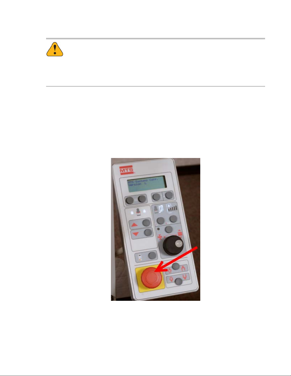
Emergency Stop Button
The frame-mounted control is equipped with an Emergency Stop button to be used for emergency purposes
only. There is also an optional Remote Emergency Stop button. The Emergency Stop buttons will shut off
power to the main actuator and crosshead lift system. To release an activated button, turn it clockwise.
The Emergency Stop button should be periodically tested by pressing it when the controller is powered
on, but not when a test is running. The controller continuously monitors the redundant Emergency Stop
chain and will generate an interlock alerting the user if any problems are detected. Pressing the Emergency
Stop button allows the active state to be checked.
Frame-Mounted Control Emergency Stop Button
MTS Acumen™| 19
Page 20
Safety Overview
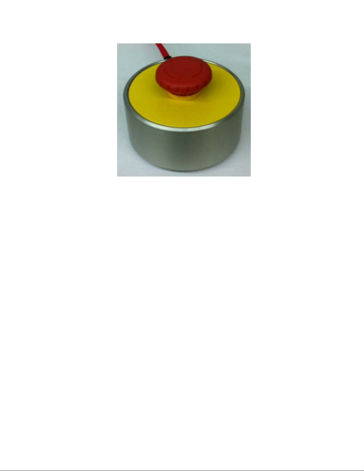
Optional Remote Emergency Stop Button
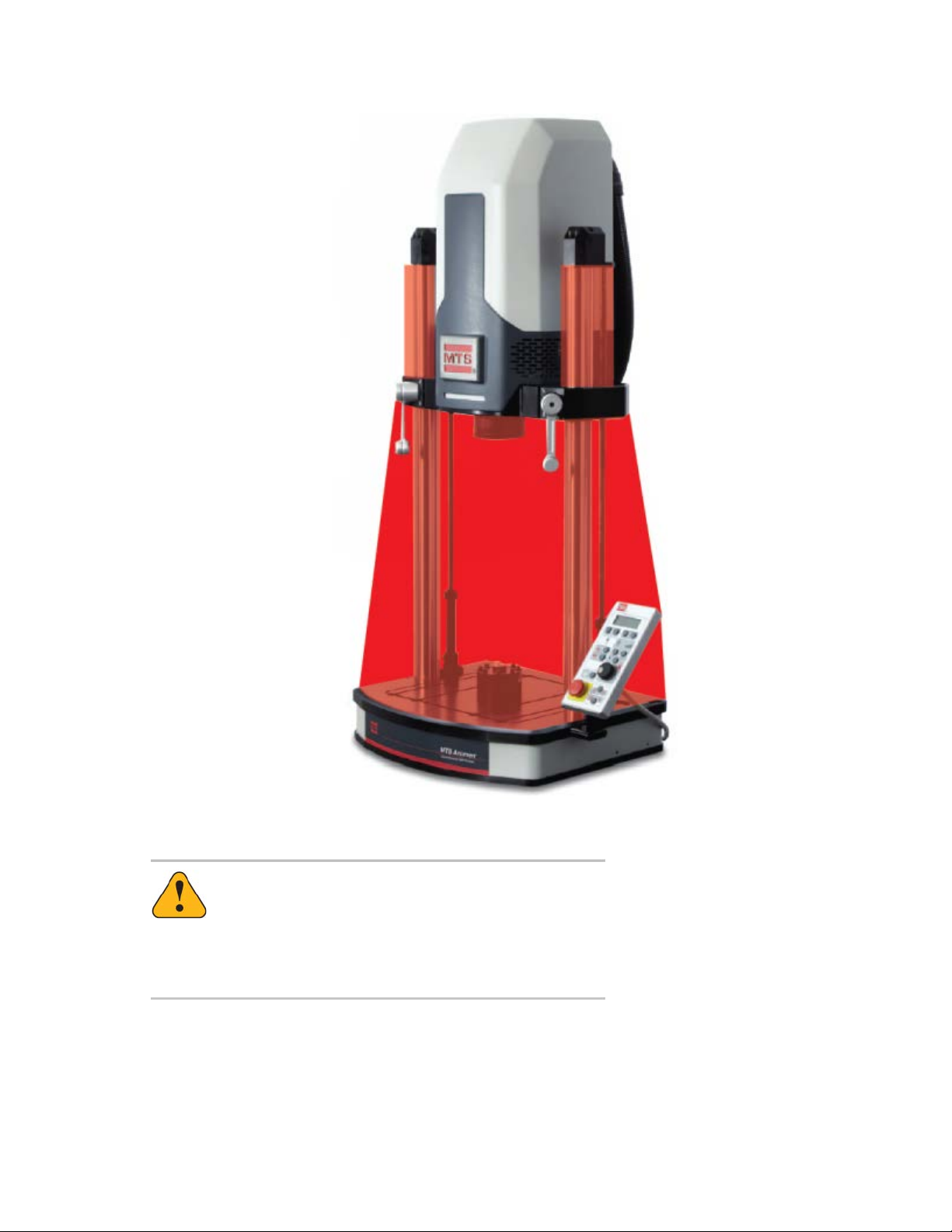
Crush Zone
A crush zone exists between the T-slot base and crosshead which is highlighted in red in the following
figure. Keep clear of this area when the actuator is in motion. Press the Emergency Stop button on the
frame-mounted control to shut off power to the motor and stop actuator motion.
20 | MTS Acumen
™
Page 21
Safety Overview
Crush Zone of an MTS Acumen System
Warning:
Applying power can result in sudden actuator motion.
A moving actuator can injure anyone in its path.
Always clear the actuator area before applying power.
MTS Acumen™| 21
Page 22

Safety Overview
Safety Information Overview
MTS systems are designed to generate single-axis or multi-axial motions and forces simultaneously in a
controlled environment and impart these motions and forces into a specimen that is secured to the system.
When you prepare to operate the system and during system operation, ensure the following:
• Do not use or allow personnel to operate the system who are not experienced, trained, or educated in
the inherent dangers associated with this system and who are not experienced, trained, or educated
with regard to the intended operation as it applies to this system.
• Do not disable safety components or features (including limit detectors, light curtains, or proximity
switches/detectors).
• Do not attempt to operate the system without appropriate personal safety gear (for example, hearing,
head, hand, and eye protection).
• Do not apply energy levels that exceed the maximum energies and velocities for the system design.
For these maximum values, see the system specifications.
• Do not use a specimen that does not meet the minimum (if applicable) or exceeds the maximum
allowable mass. For these values, see the system specifications.
• Do not use specimens that are combustible, flammable, pressurized, or explosive.
• Do not use humans as specimens or allow humans to ride in or on the specimen or the system for any
purpose unless the system is man-rated and all associated safety conditions are strictly enforced.
• Do not modify the system or replace system components using parts that are not MTS component
parts.
• Do not effect repairs using parts or components that are not manufactured to MTS specifications.
• Do not operate the system in an explosive atmosphere.
• Do not use the system in an area where uncontrolled access to the system is allowed when the system
is in operation.
22 | MTS Acumen
™
Page 23
Site Precautions
Warning:
The equipment is designed to operate in an environment where precautions have to be taken
to minimize hazards to personnel and the equipment
Ignoring hazards and failing to take necessary precautions can result in injury or death to
personnel, and damage to equipment.
Do not install or operate the system equipment in a hazardous environment.
Warning:
Hazardous situations or conditions can arise suddenly and without warning at all parts of the
system.
Safety Overview
If immediate action is not taken to remove the hazard or remove personnel from the hazard,
serious injury or death can result.
Do not operate the system unless you have full view of the equipment. If operation of the
system takes place in a remote control room (separated from the equipment), it should be
designed so that the operator has full and unobstructed view of the system equipment. Make
sure that ergonomic issues are considered in the layout of the operating area to limit operator
stress and fatigue.
Warning:
Working environments that are not designed with appropriate ventilation, lighting, heating and
cooling or non-ergonomic equipment, furniture, and equipment/furniture placements can result
in operator fatigue and stress.
Operator fatigue and stress can result in operator errors, which can result in injury to personnel
or damage to the equipment and/or specimen.
Make sure that lighting, heating, cooling, and ergonomic issues are considered in the layout
of the operating area to limit operator stress and fatigue.
MTS Acumen™| 23
Page 24

Safety Overview
Personnel Qualifications
Caution:
System installation, maintenance, setup, and operation require specialized training.
Installation, maintenance, setup, and operation of the system by unqualified personnel can
expose them, and others, to hazards that can cause death or personal injury and damage to
equipment.
Do not allow unqualified personnel to perform any of the system installation, maintenance,
setup, or operating procedures. Installation, maintenance, setup, and operating procedures
should only be performed by trained personnel.
System Hazard Zones
The area around and including the system is considered hazardous. Generally, hazards result from motions
that occur during system operation. However, there are latent pressure, overturning, and settling/unexpected
movement hazards that can occur prior to or after system operation, during specimen installation, or during
maintenance and repair.
The hazard zone includes the entire system and an additional area of at least 2 m (6 feet) around the
system perimeter.
Whenever personnel enter this defined zone they should be outfitted with adequate and appropriate safety
attire including hearing protection, safety glasses, hard hat, and safety shoes. Never wear loose fitting
clothing when in the system area. Never enter the system area when power is on.
Hazard Placard Placement
Hazard placards contain specific safety information and are affixed directly to the system so they are plainly
visible.
Each placard describes a system-related hazard. When possible, international symbols (icons) are used
to graphically indicate the type of hazard and the placard label indicates its severity. In some instances,
the placard may contain text that describes the hazard, the potential result if the hazard is ignored, and
general instructions about how to avoid the hazard.
24 | MTS Acumen
™
Page 25

Equipment Guards, Doors, and Covers
Warning:
Guards, doors, and covers are designed to protect personnel from moving parts, electrical
shock, and pressurized fluid or gas.
If guards, doors, and covers are not installed, potential hazards are exposed that can cause
injury or death. Personnel can be struck, crushed, entangled, or drawn into moving parts; hit
by flying objects launched with concussive force by the rapid expansion of pressurized gas;
sprayed from pressurized fluid that can burn and pierce; and electrocuted by exposed electrical
conductors.
Install and close all guards, doors, and covers before applying electrical power and operating
the system.
Safety Overview
Test Area Enclosure
MTS Recommends Use of a Test Area Enclosure
MTS recommends that the Load Unit be equipped with an integral Test Area Enclosure that provides
protection against hazards and containment of ejected non-projectile specimen material. The Test Area
Enclosure also enhances the security and integrity of tests by providing a barrier to unintended specimen
contact by operators and observers in addition to protecting personnel from hazards generated by moving
parts. MTS offers a Test Area Enclosure for each type of Load Unit.
The customer may elect to not have MTS supply the Test Area Enclosure. When customers decline the
MTS Test Area Enclosure, it is then the responsibility of the customer or systems integrator to safeguard
the personnel in the work area against ejected parts or materials from test specimens and to control access
to the machinery.
Additional Protection May Be Necessary
Customers or end users must evaluate risks due to ejected parts or materials from the test specimens.
Because of the wide range of applications which MTS Products are used, and over which MTS has no
control, additional protective devices may be necessary. It is MTS’ strong recommendation that the customer
or end user carry out their own product safety risk assessments to determine if additional safety devices
such as protective shielding, warning signs, and/or methods of restricting access to the product are required.
MTS Acumen™| 25
Page 26

Safety Overview
Warning:
Guards, doors, and covers are designed to protect personnel from moving parts, electrical
shock, and pressurized fluid or gas.
If guards, doors, and covers are not installed, potential hazards are exposed that can cause
injury or death. Personnel can be struck, crushed, entangled, or drawn into moving parts; hit
by flying objects launched with concussive force by the rapid expansion of pressurized gas;
sprayed from pressurized fluid that can burn and pierce; and electrocuted by exposed electrical
conductors.
Install and close all guards, doors, and covers before applying electrical power and operating
the system.
General Safety Practices
If you have system related responsibilities (that is, if you are an operator, service engineer, or maintenance
person), you should study this manual carefully before you attempt to perform any test system procedure.
You should receive training on this system or a similar system to ensure a thorough knowledge of your
equipment and the safety issues that are associated with its use. In addition, you should gain an
understanding of system functions by studying the other manuals supplied with your test system. Contact
MTS for information about the content and dates of training classes that are offered.
It is very important that you study the following safety information to ensure that your facility procedures
and the system’s operating environment do not contribute to or result in a hazardous situation. Remember,
you cannot eliminate all the hazards associated with this system, so you must learn and remain aware of
the hazards that apply to your system at all times. Use these safety guidelines to help learn and identify
hazards so that you can establish appropriate training and operating procedures and acquire appropriate
safety equipment (such as gloves, goggles, and hearing protection).
Each test system operates within a unique environment which includes the following known variables:
• Facility variables (facility variables include the structure, atmosphere, and utilities)
• Unauthorized customer modifications to the equipment
• Operator experience and specialization
• Test specimens
Because of these variables (and the possibility of others), your system can operate under unforeseen
circumstances that can result in an operating environment with unknown hazards.
Improper installation, operation, or maintenance of your system can result in hazardous conditions that
can cause death, personal injury, or damage to the equipment or to the specimen. Common sense and a
thorough knowledge of the system’s operating capabilities can help to determine an appropriate and safe
approach to its operation.
Observe the prescribed safety practices before and during system operation.
It is the user’s responsibility to take the machine out of service and contact MTS Service if discrepancies
in system operation are found.
26 | MTS Acumen
™
Page 27

Safety Overview
Safety Practices Before Operating the System
Before you apply power to the test system, review and complete all of the safety practices that are applicable
to your system. The goal, by doing this, is to improve the safety awareness of all personnel involved with
the system and to maintain, through visual inspections, the integrity of specific system components.
Read all manuals
Study the contents of this manual and the other manuals provided with your system before attempting to
perform any system function for the first time. Procedures that seem relatively simple or intuitively obvious
can require a complete understanding of system operation to avoid unsafe or dangerous situations.
Locate lockout/tagout points
Know where the lockout/tagout point is for each of the supply energies associated with your system. This
includes the hydraulic, pneumatic, electric, and water supplies (as appropriate) for your system to ensure
that the system is isolated from these energies when required.
Know facility safe procedures
Most facilities have internal procedures and rules regarding safe practices within the facility. Be aware of
these safe practices and incorporate them into your daily operation of the system.
Locate Emergency Stop buttons
Know the location of all the system Emergency Stop buttons so that you can stop the system quickly in
an emergency. Ensure that an Emergency Stop button is located within close proximity of the operator at
all times.
Know controls
Before you operate the system for the first time, make a trial run through the operating procedures with
the power off. Locate all hardware and software controls and know what their functions are and what
adjustments they require. If any control function or operating adjustment is not clear, review the applicable
information until you understand it thoroughly.
Have first aid available
Accidents can happen even when you are careful. Arrange your operator schedules so that a properly
trained person is always close by to render first aid. In addition, ensure that local emergency contact
information is posted clearly and in sight of the system operator.
Know potential crush and pinch points
Be aware of potential crush and pinch points on your system and keep personnel and equipment clear of
these areas.
An important consideration for servohydraulic systems is that when power is interrupted, it is likely that
stored accumulator pressure will persist for some time within the system. In addition, it is likely that as
stored energy dissipates, gravity will cause portions of the system to move.
MTS Acumen™| 27
Page 28

Safety Overview
Be aware of component movement with hydraulics off
For hydraulic systems, be aware that mechanical assemblies can shift or drift due to changes within
hydraulic hardware when hydraulics are turned off. This non-commanded movement is because oil can
transfer between the pressure and return ports and across internal components of the hydraulic hardware.
Be aware that this can happen and clear the area around the mechanical assemblies when hydraulics are
turned off.
Know electrical hazards
When the system electrical power is turned on, minimize the potential for electrical shock hazards. Wear
clothing and use tools that are properly insulated for electrical work. Avoid contact with exposed wiring or
switch contacts.
Whenever possible, turn off electrical power when you work on or in proximity to any electrical system
component. Observe the same precautions as those given for any other high-voltage machinery.
Make sure that all electrical components are adequately grounded. Grounds must remain connected and
undisturbed at all times.
Ensure correct cable connection
If a system cable has been disconnected, ensure that you establish the correct cable-to-connector
relationship during reconnection. Incorrect cable connections can result in improper servo loop phasing
or an open servo loop condition, either of which can cause unstable or unexpected and potentially dangerous
system motions. Verify the correct cable-to-connector relationship by observing the cable and connector
labeling and the system wiring schematics.
Keep bystanders safely away
Keep bystanders at a safe distance from all equipment. Never allow bystanders to be in close proximity
of specimens or equipment while the test is running.
Wear proper clothing
Do not wear neckties, shop aprons, loose clothing or jewelry, or long hair that could get caught in equipment
and result in an injury. Remove loose clothing or jewelry and restrain long hair.
Remove flammable fluids
Remove flammable fluids from their containers or from components before you install the container or
component. If desired, you can replace the flammable fluid with a non-flammable fluid to maintain the
proper proportion of weight and balance.
Know compressed gas hazards
Your system may contain accumulators that require a high-pressure gas precharge (pressures that exceed
138 bar [2000 psi]). High-pressure devices are potentially dangerous because a great amount of energy
is available in the event of an uncontrolled expansion or rupture.
Observe the following safety practices when you work with high-pressure air or gases:
• When you charge an accumulator, follow all the charging instructions provided in the appropriate product
information manuals. When precharging accumulators, properly identify the type of gas to be used and
the type of accumulator to be precharged.
• Use only dry-pumped nitrogen to precharge nitrogen-charged accumulators. (Dry-pumped nitrogen
can also be labeled “oil pumped” or “dry water pumped.”) Do not use compressed air or oxygen for
28 | MTS Acumen
™
Page 29

Safety Overview
precharging: the temperature increase caused by rapid gas compression can result in highly explosive
conditions when hydraulic fluid is in the presence of oxygen or compressed air.
• Always follow the recommended bleeding procedures before you remove or disassemble components
that contain pressurized gas. When you bleed a gas or remove a fitting, hose, or component that
contains a gas, remember that many gases cannot support life. Therefore, as the ratio of released gas
to oxygen increases, so does the potential for suffocation.
• Wear appropriate safety devices to protect your hearing. Escaping air or gas can create a noise level
that can damage your hearing.
• Ensure that all pressurized air or gas is bled out of a pneumatic or gas-charged device before you start
to disassemble it. A thorough understanding of the assembly and its pressurized areas is necessary
before you undertake any maintenance. Refer to the appropriate product information for the correct
bleeding procedure.
It may not be obvious or intuitive which bolts or fittings are used to restrain a pressurized area. On
some assemblies, you must remove a cover plate to gain access to the structural bolts. Sometimes, to
protect you from a rapid release of trapped gases, a small port is exposed when you remove this cover
plate. Exposing this port ensures that the gas precharge is fully bled before disassembly. However,
this is not the recommended procedure for bleeding a pneumatic or gas-charged device, because it
can expose you to the dangers of escaping compressed gas and particulates that are expelled from
the chamber or around the seals. Do not assume that cover plates and ports are installed in all the
critical locations.
Consult MTS when in doubt about the safety or reliability of any system-related procedure or modification
that involves devices that contain any type of compressed gas.
Check bolt ratings and torques
To ensure a reliable product, fasteners (such as bolts and tie rods) used in MTS-manufactured systems
are torqued to specific requirements. If a fastener is loosened or the configuration of a component within
the system is modified, refer to the system and component assembly drawings (located on the System
Documentation CD) to determine the correct fastener, fastener rating, and torque. Over torquing or under
torquing a fastener can create a hazardous situation due to the high forces and pressures present in MTS
test systems.
On rare occasions, a fastener can fail even when it is correctly installed. Failure usually occurs during
torquing, but it can occur several days later. Failure of a fastener can result in a high velocity projectile.
Therefore, it is a good practice to avoid stationing personnel in line with or below assemblies that contain
large or long fasteners.
Practice good housekeeping
Keep the floors in the work area clean. Industrial chemicals, such as hydraulic fluid, that are spilled on any
type of floor can result in a dangerous, slippery surface. Do not leave tools, fixtures, or other items not
specific to the test, lying about on the floor, system, or decking.
Protect hoses and cables
Protect electrical cables from spilled fluids and from excessive temperatures that can cause the cables to
harden and eventually fail. Ensure that all cables have appropriate strain relief devices installed at the
cable and near the connector plug. Do not use the connector plug as a strain relief.
Protect all system hoses and cables from sharp or abrasive objects that can cause the hose or cable to
fail. Use a cable cover or cable tray where cables are in traffic locations. Never walk on hoses or cables
MTS Acumen™| 29
Page 30

Safety Overview
or move heavy objects over them. Route hoses and cables away from areas that expose them to possible
damage.
Provide proper hydraulic fluid filtration
For hydraulic systems equipped with a non-MTS hydraulic power unit, make sure that hydraulic fluid
filtration is established to maintain fluid cleanliness standards as stated in the Hydraulic Fluid Care Manual
(see the System Documentation CD). Particles present in the hydraulic fluid can cause erratic or poor
system response.
Protect accumulators from moving objects
For systems equipped with accumulators, protect accumulators with supports or guards. Do not strike
accumulators with moving objects. This could cause the accumulator(s) to separate from the manifold
resulting in equipment damage and personal injury.
Record changes
If you change any operating procedure, write the change and the date of the change in the appropriate
manual.
Provide test area guards
Use protective guards such as cages, enclosures, and special laboratory layouts when you work with
hazardous test specimens (for example, brittle or fragmenting materials or materials that are internally
pressurized).
Do not exceed the Maximum Supply Pressure
For hydraulic systems and components, make sure that hydraulic supply pressure is limited to the maximum
pressure defined by the system operating limits. Read and review “System Operating Limits” for the system.
Do not disable safety devices
Your system may have active or passive safety devices installed to prevent system operation if the device
indicates an unsafe condition. Do not disable such devices as it may result in unexpected system motion.
Use appropriately sized fuses
Whenever you replace fuses for the system or supply, ensure that you use a fuse that is appropriately
sized and correctly installed. Undersized or oversized fuses can result in cables that overheat and fuses
that explode. Either instance creates a fire hazard.
Provide adequate lighting
Ensure adequate lighting to minimize the chance of operation errors, equipment damage, and personal
injury.
Provide adequate ventilation
Make sure work and maintenance areas are adequately ventilated to minimize the risks associated with
the collection of hazardous fumes (such as vaporized hydraulic fluid). This is of special concern in confined
areas where hydraulic equipment is operating at high pressure in confined areas.
30 | MTS Acumen
™
Page 31

Safety Overview
Provide means to access out-of-reach components
Make sure you can access system components that might be out of reach while standing on the floor. For
example, ladders or scaffolding might be required to reach load cell connectors on tall load units.
Safety Practices While Operating the System
Wear appropriate personal protection
Wear eye protection when you work with high-pressure hydraulic fluid, high-pressure air pressure, breakable
specimens, or when anything characteristic to the specimen could break apart.
Wear ear protection when you work near electric motors, pumps, or other devices that generate high noise
levels. This system may create sound pressure levels that exceed 70 dbA during operation.
Wear appropriate protection (gloves, boots, suits, respirators) whenever you work with fluids, chemicals,
or powders that may irritate or harm the skin, respiratory system, or eyes.
Provide test area enclosures
Use protective enclosures such as cages or shields, and special laboratory layouts when you work with
hazardous test specimens (for example, brittle or fragmenting materials or materials that are internally
pressurized).
Customer must evaluate risks due to ejected parts or materials from the test specimens. If the MTS Test
Area Enclosure option is not selected by the customer, then for protection against ejected parts or materials
from test specimens and to control access to the machinery, the Customer must provide a Test Area
Enclosure to protect personnel.
Specimen temperature changes
During cyclic testing, the specimen temperature can become hot enough to cause burns. Wear personal
protection equipment (gloves) when handling specimens.
Handle chemicals safely
Whenever you use or handle chemicals (for example, hydraulic fluid, batteries, contaminated parts, electrical
fluids, and maintenance waste), refer to the appropriate MSDS documentation for that material and
determine the appropriate measures and equipment required to handle and use the chemical safely. Ensure
that the chemical is disposed of appropriately.
Know electrodynamic system interlocks
Interlock devices should always be used and properly adjusted. Interlock devices are designed to minimize
the chance of accidental damage to the test specimen or the equipment. Test all interlock devices for
proper operation immediately before a test. Do not disable or bypass any interlock devices. The
Reset/Override button is a software function that can be used to temporarily override an interlock while
attempting to start power and gain control of the system.
Know system limits
Never rely on system limits such as mechanical limits or software limits to protect you or any personnel.
System limits are designed to minimize the chance of accidental damage to test specimens or to equipment.
MTS Acumen™| 31
Page 32

Safety Overview
Test all limits for proper operation immediately before a test. Always use these limits and adjust them
properly.
Do not disturb sensors
Do not bump, wiggle, adjust, disconnect, or otherwise disturb a sensor (such as an accelerometer or
extensometer) or its connecting cable when pressure is applied.
Ensure secure cables
Ensure that all cable connections (electrical supply, control, feedback, sensor, communications, and so
forth) are either locking type, or are secured, to ensure that they cannot be disconnected by a simple act.
Do not change any cable connections when pressure is applied. If you attempt to change a cable connection
while the system is in operation, an open control loop condition can result. An open control loop condition
can cause a rapid, unexpected system response which can result in severe personal injury, death, or
damage to equipment. Also, ensure that all cables are connected after you make any changes in the
system configuration.
Stay alert
Avoid long periods of work without adequate rest. In addition, avoid long periods of repetitious, unvarying,
or monotonous work because these conditions can contribute to accidents and hazardous situations. If
you are too familiar with the work environment, it is easy to overlook potential hazards that exist in that
environment.
Stay clear of moving equipment/avoid crush points
Stay clear of mechanical linkages, connecting cables, and hoses that move because you may get pinched,
crushed, tangled, or dragged along with the equipment. High forces generated by the system can pinch,
cut, or crush anything in the path of the equipment and cause serious injury. Stay clear of any potential
crush points. Most test systems can produce sudden, high-force motion. Never assume that your reactions
are fast enough to allow you to escape injury when a system fails.
Know the causes of unexpected actuator motions
The high force and velocity capabilities of MTS actuators can be destructive and dangerous (especially if
actuator motion is unexpected). The most likely causes of unexpected actuator response are operator
error and equipment failure due to damage or abuse (such as broken, cut, or crushed cables; shorted
wires; overstressed feedback devices; and damaged components within the servocontrol loop). Eliminate
any condition that could cause unexpected actuator motion.
Do not use RF transmitters
Keep radio frequency (RF) transmitters away from the workstation computers, remote terminals, and
electronics consoles. Intense RF fields can cause erratic operation of the more sensitive circuits in the
system.
32 | MTS Acumen
™
Page 33

System Introduction
Topics:
•
About This Manual.............................................................................................................................34
•
System Overview...............................................................................................................................35
•
Parts of the Software Interface..........................................................................................................45
MTS Acumen™| 33
Page 34

System Introduction
About This Manual
Important:
Read this entire manual before running a test.
The MTS Acumen System Operator Guide provides an overview of the MTS Acumen electrodynamic load
frame, and it provides basic guidelines for running tests using the MTS TestSuite Multipurpose (MP)
software. All personnel that use the MTS Acumen frame and MP application to run tests must be trained
in the safe use and setup of MTS equipment.
Important:
The actual test setup, safety, and run procedures must be developed by your organization based
on your unique requirements.
Intended Audience
The intended audience of this guide is MTS Acumen system operators who are responsible for running
test procedures.
Related Documentation
In addition to this guide, the Multipurpose Express and MTS Acumen family of products includes the
following documentation which you may find helpful:
•
MTS TestSuite Multipurpose Express Operator Guide
•
MTS TestSuite Multipurpose Elite User Guide
•
MTS TestSuite Multipurpose Elite Test Design Guide
•
MTS Acumen Electrodynamic Test System Load Frame User Guide
•
MTS Acumen Electrodynamic Test System Lift and Move Guide
•
MTS Acumen Electrodynamic Test System Load Frame Site Preparation Guide
•
MTS Acumen Electrodynamic Test System Test Area Enclosure Installation Guide
•
MTS Echo Software User Guide
Controller and application software manuals are typically included on the software CD. Hardware manuals
are typically included on a separate hardware CD.
34 | MTS Acumen
™
Page 35

System Overview
System Introduction
System Components
DescriptionNameItem
1
2
MTS FlexTest (Series 793)
controller software — Station
Manager application
MTS TestSuite MP software —
MTS Multipurpose (MP) Elite
and Express applications
MTS FlexTest controller software runs in the
background underneath MTS TestSuite MP. While
MTS FlexTest has a user interface, it is typically not
used with Acumen load frame systems except to
initially select a configuration and parameter set.
MTS TestSuite Multipurpose (MP) software includes
MP Elite (MPE) and MP Express (MPX) applications,
which are separately licensed products. MPE
includes the option to create complex test designs.
TestSuite MP software provides the primary
MTS Acumen™| 35
Page 36

System Introduction
DescriptionNameItem
interface for setting up and running tests with an
Acumen load frame system.
Controller3
MTS Acumen Load Frame4
The controller provides the necessary interface
between the PC and the load frame. The MTS
Acumen system with standard configuration is
supported by the MTS FlexTest Model 40 Controller,
which can support two test stations, and the MTS
FlexTest Model 60 Controller, which can support up
to four test stations. Both controllers support one
control channel per station. These controllers
provide real-time, closed-loop control with transducer
conditioning and function generation to drive various
types of servo actuators.
The MTS Acumen electrodynamic test system
provides a conventional load frame design with an
optional test area enclosure as shown below to
perform cyclic, tension, bend, and compression
tests. It has a powered, movable crosshead and
manual crosshead locks. The T-slot table provides
flexibility for fixture mounting, and the quick-change
load cell design simplifies the process of attaching
accessories to the table or crosshead. For a
description of the separate elements of the load unit,
see Load Frame Components (p. 36).
Load Frame Components
The following figure shows the components of the two-column load frame.
36 | MTS Acumen
™
Page 37

System Introduction
Two-Column Load Frame
DescriptionItem
Actuator and power electronics (behind hood).1
Columns on which the crosshead moves up and down.2
Actuator rod.3
4
9
Manual crosshead locks. (Note: crosshead locks must be in a fully locked position to run
a test.)
Frame-mounted control.5
T-slot base plate.6
Load cell mounted on table top (load cell can also be mounted on the actuator).7
Crosshead lift.8
Frame-mounted status light allows you to view system status at a glance. This status is
coordinated with the MP software System panel. Status is indicated by the following colors
and a blinking or solid light:
AC power to the frame is off.Unlit
MTS Acumen™| 37
Page 38

System Introduction
DescriptionItem
Interlocked.Red (Solid)
Red or White (Blinking)
System is in service mode. To move the system out of
service mode, slide the Service Mode switch on the upper
back of the system, and click Interlock Reset. If problems
continue, contact MTS Technical Support.
Interlock cleared, standby power is on.White (Solid)
Interlock cleared, low power.Blue (Blinking)
Interlock cleared, high power, not running.Blue (Solid)
Interlock cleared, running state.Green (Solid)
Interlock cleared, temperature warning.Yellow (Solid)
Note:
The fans to cool the actuator increase in speed with
increasing temperature and will become louder. This
is normal system operation, and it is not necessary
to shut down the system. Reducing the frequency
and/or force output of the system will allow the
actuator to cool down. The system status light will
remain yellow until the actuator has cooled down.
Frame-Mounted Control
The frame-mounted control can be attached to the left or right side of the frame. It provides controls to
help you mount fixtures and install specimens. The frame-mounted control also has an alphanumeric
display and illuminated icons to provide feedback.
Note:
When exclusive control is provided by the frame-mounted control, the actuator controls on the MP
application will be locked and overlaid by the frame-mounted control exclusive control icon:
The following figure separates the frame-mounted control into boxed sections that are described in the
table that follows.
38 | MTS Acumen
™
Page 39

System Introduction
Frame-Mounted Control
Frame-Mounted Control Description
DescriptionControlsSection
Display and display controlsA
1 Display. Shows four lines. There is a screen
for Manual Command (MC), Auto Offset (AO),
and a screen to change the power level. When
the Interlock Reset/Override button is pressed,
the screen shows the override countdown, and
you can press the Enter button to cancel the
override.
2, 3 Page forward or page back. Shows next or
previous text in the display.
MTS Acumen™| 39
Page 40

System Introduction
DescriptionControlsSection
4 Scroll. Scrolls down the text display. Selection
cycles to the top when the bottom line is
highlighted and you press the button.
5 Enter. Executes the highlighted command in
the display (for example, selecting Low and
pressing Enter would apply low power).
B
Indicators and controls related to actuator
power and control
1 Controller interlock indicator. When
illuminated, an interlock has occurred. On the
MTS TestSuite software, hover your cursor over
the red system error icon in the Status panel for
the cause of the interlock, or click the open
window icon to view all status indicators.
2 Door Open (only active with optional test area
enclosure). When illuminated, the door to the
test area enclosure is open, High-Power Prohibit
is activated, and the system is in High-Speed
Prohibit mode (see High-Power Prohibit Mode
(p. 18)). When the door is closed, the door
indicator is not visible.
3 High-Power Prohibit indicator. When
illuminated, the machine is in High-Power
Prohibit mode. The machine can be put into
High-Power Prohibit mode by pressing the
High-Power Prohibit button or by opening the
door of the optional test area enclosure.
4 Power Indicator. Two bars = Low Power, Five
bars = High Power.
40 | MTS Acumen
5 Button to reset interlocks and override them
temporarily (30 seconds). Each time you press
the button, another 30 seconds is added to the
override time which gets shown on the display
(see A1). If you reset an interlock from the
frame-mounted control, MTS recommends that
you press Enter to cancel the override.
Important:
When you press this button, all limits are
overridden.
6 High-Speed Prohibit button. Press to toggle
High-Power Prohibit mode (see High-Power
Prohibit Mode (p. 18)) on and off. High-Power
Prohibit mode prevents the actuator from going
into the Power High state.
™
Page 41

System Introduction
DescriptionControlsSection
C
D
Manual actuator control toggle button and
rotary dial
1 Manual Actuator Control Indicator. When
illuminated, manual control of the actuator is
active, and you can adjust the actuator using
the Actuator Control Dial (3).
2 Actuator Control Enable button. Press to
enable actuator positioning using the rotary dial;
press again to disable actuator positioning using
the rotary dial. Illumination of indicator (1)
signifies that the actuator control is enabled.
3 Actuator Control Dial. Turn clockwise to move
the actuator in tension (retract) direction. Turn
counter clockwise to move the actuator in
compression (extension) direction. The control
dial operates in the active control mode.
Grip control toggle buttons (work only with
optional, external pneumatic grip supply)
1 Upper Pneumatic Grip Control button. Press
to close the upper grip fixture; press again to
open the upper grip fixture.
2 Lower Pneumatic Grip Control button. Press
to close the lower grip fixture; press again to
open the lower grip fixture.
Emergency Stop buttonE
Press to stop the test and shut off power to the
main actuator and lift system but retain power
to the rest of the electronics in the frame.
Because power to the actuator is cut, gravity
may cause the actuator to drop before the brake
is applied. This may cause operator harm or
specimen damage. To release emergency stop
action, turn the red button clockwise (as shown
by arrows on button).
Exclusive control toggle buttonF
Press for the frame to be managed from the
frame-mounted control only. The icon illuminates
when exclusive control is active. Press again to
release control from the frame-mounted control
to MTS TestSuite software. Many control
functions require exclusive control to be active.
MTS Acumen™| 41
Page 42

System Introduction
DescriptionControlsSection
G
Crosshead manual lock indicators and
crosshead positioning buttons
1 Left Crosshead Manual Lock icon. When
illuminated, the left crosshead manual lock
handle is in the fully locked position. When not
illuminated, the handle is in the fully unlocked
position. When blinking, the handle is in an
intermediate position.
2 Right Crosshead Manual Lock icon. When
illuminated, the right crosshead manual lock
handle is in the fully locked position. When not
illuminated, the handle is in the fully unlocked
position. When blinking, the handle is in an
intermediate position.
3 Crosshead Up button. Press to raise the
crosshead. The crosshead must be fully
unlocked to move the crosshead.
4 Crosshead Down button. Press to lower the
crosshead. The crosshead must be fully
unlocked to move the crosshead.
Fixtures
MTS offers a variety of optional fixtures for the MTS Acumen systems. There are two standard mounting
kits, a threaded kit and a pin adapter kit.
Some common fixtures include:
• Pneumatic grips (wedge or bollard)
• Manual grips (screw or vise action)
• Aluminum compression platens
• Bend fixtures
• Bionix EnviroBath used for testing medical
devices or biomaterial specimens in fluids
The image on the right shows a specimen mounted
in pneumatic wedge grips for a tension test. For
details about mounting the particular fixtures and
grips required for your specimen, see the
documentation that came with the hardware.
Pneumatic Wedge Grips
42 | MTS Acumen
™
Page 43

System Introduction
Load Cell
A load cell is a transducer that converts a mechanical force or load into an electrical output signal. The
system load cell has an integrated accelerometer that allows MTS TestSuite MP software to measure
acceleration and compensate for inertial errors.
The MTS Acumen system table has a piloted interface that makes it easier to mount the load cell and
fixtures. The load cell can be mounted on the actuator or the T-slot table top. The following figure shows
a system with the load cell mounted on the actuator (on the left) and a system with the load cell mounted
on the table top (on the right).
Actuator Mounted (Left) and Table Mounted Load Cells (Right)
Mounting the load cell directly to the actuator provides full access to the T-slot table for fixture and test
setup. A piloted load cell mount helps reduce alignment errors and minimizes the need for a separate
alignment fixture.
If the test fixturing allows the load cell to be mounted in either orientation, the table mounted load cell
configuration is recommended. This reduces the need for setting up acceleration compensation, reduces
wear to moving cables, and reduces the risk of damage to the load cell.
MTS Acumen™| 43
Page 44

System Introduction
There are eight bolts associated with the load cell.
Four of the eight holes around the perimeter of the
load cell (see the photo on the right) are used for
mounting. The others are used to assemble the load
cell and should not be manipulated by the user. The
middle bolt hole is used to mount fixtures to the load
cell.
The following low-force load cells are optionally
provided. They do not contain an accelerometer and
are designed to be tandem-mounted, utilizing the
system cell's accelerometer for compensation.
• 500N load cell kit
• 250N load cell kit
• 125N load cell kit
Main Power Switch (I/O)
Controller Power
System Load Cell
The main power switch for the controller is located on the back of the controller unit. Press position I to
turn the power on to the controller. Press position O to turn off power to the controller.
FlexTest Controller Power Switch
Load Frame Power
The main power switch for the MTS Acumen load frame is located on the back side of the load frame base.
Press position I to turn the power on to the load frame. When the power is on, the frame-mounted status
light on the front of the hood illuminates. Press position O to turn off power to the load frame.
44 | MTS Acumen
Load Frame Power Switch
™
Page 45

System Introduction
Note:
In case of emergency, power can also be removed from the frame or controller by removing the
detachable power cord.
Parts of the Software Interface
Main Window
When you initially start the MTS TestSuite MP application, the main window appears. See the following
figure and table to understand the major components of the MTS TestSuite MP main window:
Main Window
DescriptionItemNumber
1
Quick Access toolbar
and menus
Allows you to start a new test run, open an existing test, create
a new test from a template, save a test, and save a test as a
template. For details, see Quick Access Toolbar (p. 47). For
MTS Acumen™| 45
Page 46

System Introduction
DescriptionItemNumber
more information about the menu options, see the MTS TestSuite
Multipurpose Elite User Guide.
System panel2
Provides indicators for system status, crosshead locks, open
enclosure door, and interlocks. For details, see System Panel
(p. 47) and Status Panel (p. 49).
Actuator Power panel3
Allows you to turn off power to the actuator, turn on low power,
and turn on high power. For details, see Actuator Power Panel
(p. 53).
Manual Control panel4
Allows you to move the actuator manually. For details, see Manual
Control Panel (p. 53).
Program Control panel5
Allows you to start, hold, or stop the test run. For details, see
Program Control Panel (p. 56).
Test Run Status panel6
Provides the status of the test and a button to start or stop the
procedure. For details, see Test Run Status Panel (p. 56).
Explorer panel7
Shows a hierarchical view of information related to the test,
including user workflow and test setup (for test designers).
Element panel8
When you click an element on the Explorer tab, the Element
panel shows radio buttons, boxes, and slider controls to make
modifications to that element.
9
46 | MTS Acumen
Situational Awareness
panel
Layer Control panel10
Meters and Error List11
Application Log12
™
Shows interactive diagrams for specified sensors, where you can
change settings. For details, see Situational Awareness Panel
(p. 58).
Allows you to toggle on and off various layers of information on
the Situational Awareness panel. For details, see Layer Control
Panel (p. 66).
The Meters tab shows the current numeric value of the selected
signals. Right-click a meter to add a meter and access other
options or select Properties to open the Meter Configuration
window.
The Error List tab (not shown) shows error and warning
messages that describe both critical and noncritical conditions in
the test definition. The Error List is dynamic and changes
according to the part of the application you are using.
Shows status information about application events in recent
history, such as logging into the application, exiting the application,
and interlock conditions present prior to opening tests. The
application stamps each message with the type of message,
Page 47

System Introduction
DescriptionItemNumber
generation date, and time. Right-click within the Application Log
tab to open the existing log file, add a custom note to the log,
clear all messages from the log, or export the contents to a
Microsoft Excel file. Messages persist from one session to another.
Quick Access Toolbar
Use the Quick Access toolbar to open new tests, initiate test runs, set application preferences, adjust
display settings, and perform other general MPE or MPX actions. See the following for a list of the key
actions you can perform from the Quick Access toolbar.
Quick Access Toolbar
Control Panels
System Panel
DescriptionIcon
Click to start a new test run.
Click to open an existing test. The Open Test window opens where you can select a
recent test, a test from a Project folder, or a test from another location on your computer.
Click the arrow to select New Test from Template, New Test from Existing Test, or
New Test from File (which opens the C:\MTS TestSuite\External Files directory).
Click to save changes to the current test.
Click to save the current test as a template. You must have the Save Test as Template
privilege to execute this function. If you require this function, talk to your administrator
to modify your user role.
The System panel provides status indicators for system power, crosshead locks, enclosure door, system
temperature, and controls for resetting and overriding an interlock. When the power to the frame is off,
actuator power is also off and power buttons are disabled. When a fault status indicator is triggered, the
Interlock/Override button is enabled, and other panel buttons are disabled until the interlock is reset.
MTS Acumen™| 47
Page 48

System Introduction
System Panel Icon
DescriptionIconNumber
The system is ready.1
System warning. A system warning indicates that action may be required
to achieve desired operating results, but most operations can still generally
be performed when a system warning occurs. Hover your cursor over the
icon to see the warning message.
System error. A system error has occurred that may prevent some
operations, such as applying power to the system, moving the actuator,
or clicking the Run button to run a test. Hover your cursor over the icon
to determine the cause of the system error.
Depending on the system error that has occurred, you may still be able
to perform some operations. For example, a C-Stop Interlock allows power
to the system, but you cannot move the actuator. If a Program Stop
Interlock occurs, power is allowed to the actuator and you can manually
move the actuator, but you cannot perform test runs until the system error
is resolved.
2
Manual crosshead lock. Indicates whether the crosshead is locked. The
icon to the left shows that the left side of the crosshead is unlocked and
the right side is locked. To apply high power, both sides must be locked.
3
Door open. Indicates whether the door to the test area enclosure is open
or closed. When the icon is illuminated, the door is open. To apply high
power, the door must be closed.
4
Yellow temperature sensor. Indicates that the actuator is getting warm.
The system will continue to run until a temperature limit is reached.
The fans to cool the actuator increase in speed with increasing
temperature and will become louder. This is normal system operation,
and it is not necessary to shut down the system. Reducing the frequency
and/or force output of the system will allow the actuator to cool down.
Red temperature sensor. Indicates that the actuator is too hot. The system
will interlock until the actuator is cool enough to run.
48 | MTS Acumen
™
Page 49

System Introduction
DescriptionIconNumber
5
Reset Interlock. Click to reset the interlock, or click the drop-down arrow
to select Reset Interlock or Override Interlock.
Override Interlock. Selecting this option overrides interlocks for 30
seconds. Use of this button is not recommended for Acumen systems.
Warning:
Clicking the Override Interlock button will override ALL limits
for 30 seconds each time the button is pressed including the
Axial Acceleration Limit which is designed to limit damage
due to unexpected actuator motion.
Unexpected actuator motion may result in injury or equipment
damage.
Use of the Override Interlock function is not recommended
for Acumen systems.
To cancel an override, click the Reset Interlock button.
6
Frame status indicator. Blinks to indicate which load frame is associated
with the station when you select Controller > Identify Frame. This status
light corresponds to the Frame-Mounted System Status on the front hood
of the load frame. For more information about what each status light
indicates, see Load Frame Components (p. 36).
7
Click to open the Status Indicator window and view a list of status controls.
Red lights indicate which status indicators are triggered. For more
information about each status indicator and what you can do to resolve
triggered status indicators, see Status Panel (p. 49).
Status Panel
The Status panel shows a red indicator when a fault status has been triggered. Hover your cursor over
the red indicator on the panel to see a message explaining the error. Click the open window icon to see
a list of all status indicators. The following table describes the status indicators and the corrective action
to take when an error occurs.
MTS Acumen™| 49
Page 50

System Introduction
Note: The red indicators above are typical of a tripped E-Stop.
Status Panel
Corrective ActionErrorStatus IndicatorItem
Power1
See individual status information.Active items in this
category cause power to
be removed from the
main actuator and lift
system.
E-stop2
The Emergency-stop
circuit is active.
If no safety faults are active, verify that the
Emergency-Stop button on the
frame-mounted control is cleared. Also verify
that the remote Emergency-Stop button is
cleared or that a jumper plug is installed in
its place.
Safety fault3
See individual status information.Active items in this
category indicate that a
safety-related fault has
occurred.
4
Accessory
E-stop/safety relay
status
The accessory safety
relay monitored state
does not match
commanded state.
Verify that the Remote/Accessory
Emergency-Stop cable is attached securely.
If a remote Emergency-Stop is not used,
check that a jumper plug is installed in its
place.
50 | MTS Acumen
Shut down the software and cycle power to
the frame to reset this fault status. If the fault
persists, contact MTS Technical Support.
™
Page 51

System Introduction
Corrective ActionErrorStatus IndicatorItem
5
6
Safety velocity
monitoring status
E-stop switch
status
Velocity > 10 mm/s is
detected while in
High-Power Prohibit
mode, which is active
when the High-Power
Prohibit button is active
or the optional test area
enclosure door is open.
The system has shut
down to protect the
operator. If there is large mass (fixturing) attached to
redundant
Emergency-stop switch
circuits do not match.
Check that the control mode and tuning are
appropriate for the current setup.
If this error occurred while trying to turn on
low power, there may be stored energy in
the system causing the actuator to move
when the brake is released. Close the test
area enclosure door or de-activate the
High-Power Prohibit button on the
frame-mounted control. Click Power Low.
the actuator, adjust the output offset to
increase the initial current to the actuator
when it is enabled.
Press the Interlock Reset button to clear this
fault.
Check that all cables are attached securely.The state of the
Pressing Emergency-Stop buttons too slowly
may also cause this fault.
Resetting this fault status requires shutting
down the software and cycling power to the
frame. If the fault persists, contact your MTS
service engineer.
9
10
11
Other7
Controller Interlock8
Controller interlock
source active
Motor temperature
over limit
Motor temperature
warning
occurred that requires
servicing.
controller interlock
elements has tripped.
items on the MTS
Acumen frame that
would cause the
Controller Interlock to be
active.
The motor temperature
exceeds limit.
(Warning only) The
motor temperature is
warm.
Contact MTS Technical Support.A safety system fault has
See individual status information.One of the subordinate
See individual status information.This category contains
This interlock can be cleared once the motor
temperature returns to its operating range.
Press Interlock Reset to clear this fault.
The frame will continue to run in this state
without damage, but the motor temperature
is approaching its limit.
MTS Acumen™| 51
Page 52

System Introduction
Corrective ActionErrorStatus IndicatorItem
The fans to cool the motor increase in speed
with increasing temperature and will become
louder. This is normal system operation, and
it is not necessary to shut down the system.
Reducing the frequency and/or force output
of the system will allow the motor to cool
down.
Ambient air temperature may be too high.
Check that air intake and exhaust vents on
the MTS Acumen frame are clean and not
obstructed.
14
15
16
Other12
Gate Interlock13
Safety enclosure
status
'High-power
prohibit' button
status
Crosshead lock
status
less common fault
conditions. Also lights
whenever the
Emergency Stop is set.
allowed to run in this
state.
enclosure is open. The
system will not allow
high power.
The High-Power Prohibit
button on the
frame-mounted control
is active. The system will
not allow High Power.
crosshead is unlocked.
Refer to the message log for details.Status indicator to cover
See individual status information.Programs are not
Press Interlock Reset to clear this fault.
Close the door to the test area enclosure.The door to the test area
Press the High-Power Prohibit button on the
frame-mounted control to toggle its state.
Lock the crossheads.One or both sides of the
17
18
52 | MTS Acumen
Left crosshead
lock status
Right crosshead
lock status
Watch Dog19
™
The left side of
crosshead is not fully
locked.
The right side of
crosshead is not fully
locked.
Communication to the
frame has been lost.
Verify that the left crosshead lock handle is
in the fully locked position and the left
crosshead lock icon on the frame-mounted
control is illuminated.
Verify that the right crosshead lock handle
is in the fully locked position and the right
crosshead lock icon on the frame-mounted
control is illuminated.
Verify that the Frame Status cable is
connected securely and that the frame is
powered on.
Page 53

System Introduction
Corrective ActionErrorStatus IndicatorItem
Restart the system controller software to
clear this fault.
20
21
Watchdog timeout
Watchdog error
in communication
between the controller
and the frame.Watchdog reset22
See Watch Dog above.Indicate an interruption
Actuator Power Panel
Use the Actuator Power panel to control power to the actuator. You must apply low power (two of five bars)
before you can apply high power (five bars) to the system. When an interlock is triggered, the power buttons
are disabled until the interlock is reset. If a controller is not connected or frame power is off, the actuator
power buttons are disabled.
Actuator Power Panel
DescriptionIcon
Power off button. Click to turn off power to the actuator.
Power Low button. Click to apply low power to the actuator. While the actuator is in low
power, you can perform some tasks, such as opening the door of the test enclosure,
installing fixtures, installing the specimen, and so on. You must apply low power before
you can apply high power.
High-Power Prohibit indicator. This indicator illuminates if there is an open door on the
optional test area enclosure or if the High-Power Prohibit button is active on the
frame-mounted control. When illuminated, velocity is limited, and the system will not allow
high power to be applied to the actuator.
Power High button. Click to apply high power to the actuator. You must apply low power
before you can apply high power.
Manual Control Panel
Use the Manual Control panel to position the actuator. You can configure the actions of the Retract, Extend,
and Home jog buttons on the Preferences menu > Configuration > Control Panel tab.
MTS Acumen™| 53
Page 54

System Introduction
Manual Control Panel
DescriptionIcon
Retracts the actuator and applies tension to the specimen.
Extends the actuator and applies compression to the specimen.
Moves the test station actuator to the predefined home position.
Click to open the Manual Control window.
Manual Control Window
The Manual Control window allows you to modify the control settings. To open the Manual Control window,
click the open window icon on the Manual Control panel.
Manual Control Window
DescriptionNameItem
54 | MTS Acumen
™
Select the control channel.Channel1
Active Control Mode2
Shows the current control mode. Click Apply to make a
selected control mode the active control mode.
Page 55

System Introduction
DescriptionNameItem
Select a control mode.Control Mode3
Applies the manual command to the actuator.Command4
If necessary, click the cog wheel icon to open the Slider
Settings window, where you can change the slider-bar
range.
If you select a Master Command Group that has individual
channels at different Command values, this control shows
the highest and lowest Command values for the Group.
Additionally, it shows pointers and extension/retraction
symbols that indicate the highest and lowest Command
values. Pointers lock together once they have been used
to move the Group to a common Command value.
To modify the slider settings, click the cog wheel icon next to the Command box. The Slider Settings
window opens.
Slider Settings Window
DescriptionNameItem
Jog Increment1
Select how far the actuator will move when you press the
Retract or Extend button on the Manual Control panel in
the increments specified in the Resolution box.
MTS Acumen™| 55
Page 56

System Introduction
DescriptionNameItem
Select the units of measurement shown on the slider control.Display Unit2
3
Range Minimum,
Range Maximum
Resolution6
Indicates the minimum and maximum range allowed on the
slider according to the units of measurement in Display
Unit.
Enter the minimum range for the slider control.Range Minimum4
Enter the maximum range for the slider control.Range Maximum5
The smallest increment used in the slider range and the
distance it will move when you click the slider arrows.
Program Control Panel
Use the Program Control panel to start, pause, and stop a test run.
Program Control Panel
DescriptionControl
Run — Start a test, resume a test that is held, or restart a test procedure that
is stopped. When the test is in the Run state, the button illuminates, and the
background is black.
Hold — Pause the test at the end of the current cycle or at the end of the current
non-cycle command activity. Click Run to resume the test run. You cannot
unload a test run that is held. When the test is in the Hold state, the button
illuminates, and the background is black.
Stop — Stop the test in place. The current cycle or command activity is not
completed. Click Run to restart the test. You can unload a test that is stopped.
When the test is stopped, the button illuminates and the background is black.
Test Run Status Panel
The Test Run Status panel provides a Stop Procedure button and information about which test run is being
processed, its status, and running time.
56 | MTS Acumen
™
Page 57

System Introduction
Test Run Status Panel
DescriptionItem
Stop
Start
Test Run Status
Stop the procedure. This button becomes active when a test is in the Initialized or
Stopped status and a test run is selected. The button is inactive when the status is
Running or Completed. The button is inactive when a test run is not selected. To
make the button active when a test is running, click Stop or Stop At.
When you click the Stop the Procedure button, the arrow changes color. The
application panel and test panel buttons become unavailable. The Results tab
appears. The status is Stopped.
Start the procedure. This button becomes active when you click the Stop button. The
status is Stopped.
When you click the Start button, a message prompts you to click Yes to save the
project and continue the test or to click No. If you click Yes, the button changes color.
The status is Stopped. The Run and Stop buttons become active.
If you click No, the test status remains unchanged and the Start button remains
active.
Initialized—The test procedure is loaded. The project must be saved for the test to
continue.
Running—The test is in progress. The Running Time box shows the current elapsed
run time. The time that elapses while the test run is held or stopped is not included.
Holding—The test run is held at the end of the current cycle. The Running Time
box does not change until the test run is restarted. The test resumes at the start of
the next segment.
Stopped—The test run is stopped in place. If the test was in a cycle, the cycle
completes before the test stops. The Running Time box does not change until the
test run is restarted. The test restarts at the beginning of the current cycle. The test
run can be manually unloaded while in this state.
Completed—The test run is complete and is automatically unloaded.
MTS Acumen™| 57
Page 58

System Introduction
DescriptionItem
Control Mode
Shows the control mode between parentheses ( ) when connected to a station. Control
modes are controller-dependent.
Note:
The active control mode is shown for one channel only if there is one channel
with more than one mode.
Situational Awareness Panel
Caution:
Although the actuator shown in the virtual diagram will move as you change settings, the
crosshead shown in the diagram remains stationary. The space you see between the crosshead
and table top on the diagram is not consistent with the space on the actual load frame.
Moving the actuator when there is inadequate space between the crosshead and the table
top can cause load cell or specimen damage.
Before moving the actuator, ensure there is adequate space between the crosshead and table
top on the actual load frame.
The Situational Awareness panel shows virtual diagrams for signals that you want to monitor and modify
(see the following figure). If they are not viewable on the panel, you may have to move the horizontal scroll
bar to the right.
58 | MTS Acumen
™
Page 59

System Introduction
Situational Awareness Panel Showing Two Signals
Situational Awareness Panel Controls and Icons
On both sides of the frame diagram, there are small horizontal bars called thumb controls (see the following
figure). The thumb controls on the left side of the diagram modify the settings for the fixture limits (for more
information about setting fixture limits, see Setting Fixture Limits (p. 156)). The thumb controls on the right
side of the diagram modify the settings for the specimen limits (for more information about setting specimen
limits, see Setting Specimen Limits (p. 163)). If the thumb controls are not visible, click the Show the Fixture
Limit-Sliders and Show the Specimen-Limit Sliders buttons on the Layer Control panel (for more information
about the Layer Control panel, see Layer Control Panel (p. 66)).
MTS Acumen™| 59
Page 60

System Introduction
Situational Awareness Panel
DescriptionIconItem
1
Thumb control for setting a fixture protection limit. When you move
the thumb control, the selected value appears. For more information,
see Setting Fixture Limits (p. 156).
Important: When setting limits, be sure to enable them! Blue
indicates an enabled limit while gray indicates a disabled limit.
Right click on the thumb control to change the status of a limit.
2
Indicates tension. Observe the virtual load frame image for the + or
- sign to determine if tension was set to positive or negative during
the Install Fixturing phase.
3
Indicates compression. Observe the virtual load frame image for the
+ or - sign to determine if tension was set to positive or negative during
the Install Fixturing phase.
4
Magnifying icon, which magnifies the actuator rod and thumb controls.
For more information, see Magnifying the controls in this section.
60 | MTS Acumen
™
Page 61

System Introduction
DescriptionIconItem
5
6
7
Magnifying the Controls
You can magnify the actuator rod and thumb controls by clicking the magnify icon in the lower right corner
of the frame diagram. This allows you to more easily adjust limits when the thumb controls are extremely
close on the load frame diagram. The slider control at the top of the magnified panel can be used to provide
even greater magnification. The green lines in the following figure show the area of the diagram that is
magnified. You can click-and-drag anywhere within the magnified diagram and to move the focus of the
actuator to highlight different areas within the space between the crosshead and table top. This allows you
to make finer adjustments to limits using the thumb controls.
Control icon, which opens the manual control panel allowing you to
move the actuator using manual controls. For more information, see
Moving the actuator using manual controls in this section.
Minus sign, which corresponds to the tension or compression symbol
shown across the load frame. In this example it is shown across from
the compression symbol indicating that compression is negative. For
information on changing this convention, see Install Fixturing
Plus sign, which corresponds to the tension or compression symbol
shown across the load frame. In this example it is shown across from
the tension symbol indicating that compression is positive. For
information on changing this convention, see Install Fixturing
MTS Acumen™| 61
Page 62

System Introduction
Note:
Limit detectors are sensors within the system that detect when the minimum and maximum limit
values you select have been triggered. To enable or disable the limit detectors for a particular limit,
right-click the thumb control and select the On or Off radio button.
Axial Displacement Magnify Panel
Moving the Actuator Using Manual Controls
To move the actuator using manual controls, click the Control icon in the lower right corner of the diagram.
This panel also allows you to modify the Manual Command Control Settings. To open the Manual Command
Control Settings window, click the cog wheel icon next to the Command box. The green lines in the
following figure show the Manual Command Control Settings panel opening after clicking the cog wheel.
62 | MTS Acumen
™
Page 63

System Introduction
Manual Command Control Settings Window Description
DescriptionControlItem
Select the rotary dial or slider control.Manual Command Control1
Jog Increment2
Display Unit3
Select how far the actuator will move when you press the
Retract or Extend button on the Manual Control panel in the
increments specified in the Resolution box.
Select the units of measurement shown on the selected control
interface in the Command box.
MTS Acumen™| 63
Page 64

System Introduction
DescriptionControlItem
4
Range Minimum, Range
Maximum
Indicates the minimum and maximum range allowed on the
manual control according to the selected units of measurement.
Select the minimum range for the manual control.Range Minimum5
Select the maximum range for the manual control.Range Maximum6
Resolution7
Smallest increment used in the manual control range and the
distance the actuator will move when you click the slider arrows
or when you click the tension or compression icons (when you
are using the dial).
Axial Force Diagram
The controls and icons described for the Axial Displacement diagram in the preceding sections also apply
to the Axial Force diagram.
The green lines in the following figures show the use of the magnification icon and the control icon.
64 | MTS Acumen
™
Page 65

System Introduction
Axial Force with Magnify Panel
MTS Acumen™| 65
Page 66

System Introduction
Axial Force with Control Panel
Layer Control Panel
The MTS Acumen system uses layers on the main window display of the frame so you can visualize the
logical architecture of your system. It highlights the physical components of your system and associates
them with the configuration changes you can make on the layered interface. The Layer Control panel has
six toggle buttons and a button to open the Add/Reorder Signal Views window. The panel is located in the
upper left corner of the main window, and it allows you to hide or show various aspects of the configuration
information and the context-sensitive help.
When a button is enabled, it will appear yellow. The following table describes each button within the Layer
Control panel.
Layer Control Panel
66 | MTS Acumen
™
Page 67

System Introduction
Hides or shows the...Icon
Fixture limit sliders.
Specimen limit sliders.
Fixture and specimen limit values.
Offset reference. When you apply inertial compensation (Compensate for Fixturing on
the Explorer tab), a secondary offset is applied for Axial Force to offset the force caused
by gravity on the fixturing. You cannot clear this static offset, which shows up on the right
side of the Axial Force diagram on the Situational Awareness panel. If you do not apply
inertial compensation, this offset is not shown. Hover your cursor over this offset in the
situational awareness panel to see a tooltip explanation.
Range of the last peak and valley applied.
Help indicators.
Click to open the Add/Reorder Signal Views window where you can add or remove signal
views or customize the order in which the signal views are shown in the Situational
Awareness panel. The signal views appear horizontally left-to-right on the Situational
Awareness panel according to the top-to-bottom ordering specified in the Selected Signal
Views list.
MTS Acumen™| 67
Page 68

Page 69

Key Concepts
Topics:
•
About This Chapter............................................................................................................................70
•
Using the E-Stop Control...................................................................................................................70
•
Understanding Your MTS Software...................................................................................................70
•
Understanding MTS Applications and File Types..............................................................................72
•
Understanding the Control Loop........................................................................................................75
•
Understanding Control Modes...........................................................................................................76
•
Understanding the Low Power Actuator State..................................................................................78
•
Understanding High-Power Prohibit..................................................................................................78
•
Positioning the Crosshead and Actuator for the Test........................................................................79
•
Understanding Nested Limits............................................................................................................80
•
Using Detectors and Actions to Protect Yourself and Your Equipment.............................................85
•
Understanding Interlocks...................................................................................................................87
•
Understanding the Load Train...........................................................................................................90
•
Optimizing System Response Before Testing...................................................................................91
•
Understanding and Resolving Error Conditions................................................................................93
•
MTS Echo Software...........................................................................................................................94
MTS Acumen™| 69
Page 70

Key Concepts
About This Chapter
This chapter, as well as the information in the Safety chapter, contains information you should know before
you attempt to run tests with your MTS Acumen system. This information applies to the typical system
used throughout this manual and the test used in the Running the Example Spring Test chapter.
For information that applies to other tests or system configurations, see:
•
The Best Practices for Other System Configurations and Tests chapter in this manual
• Individual component product manuals included in the System Documentation found under the Start
Menu on the user interface PC
Using the E-Stop Control
If something unusual occurs that requires immediate action, use the Emergency Stop (E-Stop) control
to:
• Stop whatever setup operation or test you have in progress, and
• Remove power from the motor that drives the actuator.
While using your system, always keep in mind where the Emergency-Stop control is and what it does. The
Emergency-Stop control is located on the frame-mounted control. It is a large red button on a yellow striped
background. The Emergency Stop switch stays activated until you twist the knob as indicated by the arrows.
Understanding Your MTS Software
Your MTS system includes two software packages:
• MTS FlexTest controller software
• MTS TestSuite test software
MTS FlexTest (Series 793) Software and the Station Manager Application
MTS FlexTest (also referred to as Series 793) software is the operating system that runs underneath MTS
TestSuite. While MTS TestSuite software is your primary user interface, you should be aware that MTS
FlexTest software also has a user interface. MTS FlexTest software includes several applications. You
can access Project Manager, Station Builder, Station Manager, Hwi Editor, and so on, from the Start >
All Programs > MTS 793 Software directory, or by clicking desktop icons.
70 | MTS Acumen
™
Page 71

Key Concepts
MTS FlexTest (Series 793) Controller Software Start Menu Directory and Desktop Icon
It is important to understand that the only MTS FlexTest application you need to use to perform tests is
the Station Manager application. You typically limit your use to launching the Station Manager application
and selecting a Station Configuration and associated parameter set. After that, you typically minimize the
Station Manager application while you use the MTS MPE or MPX application to set up and perform tests.
If you create a desktop shortcut for MTS MPX that links your controller and Station Configuration, you may
not have to use MTS FlexTest software at all during typical use, though it will be running in the background.
MTS TestSuite Software
MTS TestSuite software includes several applications. Depending on your installation, you may be able
to access MTS Multipurpose Elite (MPE), MTS Multipurpose Express (MPX), MTS Fatigue Analyzer, and
so on from the Start > All Programs > MTS TestSuite directory, or by clicking desktop icons.
MTS TestSuite Testing Software Start Menu Directory and Desktop Icon
It is important to understand the following:
• To run tests on your station, the only MTS TestSuite software you need is the MTS MPX application.
MTS Acumen™| 71
Page 72

Key Concepts
Note: The MTS MPE application can be configured for operators. In that configuration, it has
the same capabilities as the MTS MPX application.
• MPX operates in parallel with the Station Manager application. So while running tests, you must keep
the Station Manager application operating at all times to maintain control of the system. (You typically
minimize the Station Manager application after using it to set up your station.)
Understanding MTS Applications and File Types
File Types
When setting up and running tests, you interact with a number of different file types:
Station File Types
DescriptionFile Type
MTS FlexTest Project
Files
MTS TestSuite Project
Files
Configuration Files
A FlexTest project is a collection of files related to the Station Configuration.
When you open a configuration, it opens in the context of its parent project.
Files associated with configurations, such as sensor calibration files and
parameter sets, are linked to configurations within the project directory.
FlexTest projects are not associated with MTS TestSuite projects.
An MTS TestSuite project is a collection of file path settings related to MP
test procedures. When you open a test, it opens in the context of its parent
project. Files associated with tests, such as external files and report
templates, are linked to tests with project settings. MTS TestSuite projects
are not associated with FlexTest projects.
A Station Configuration file (.cfg) defines the controller resources allocated
to a particular station. The following figure illustrates how the configuration
file you open to perform the Example Spring Test relates to the station.
72 | MTS Acumen
™
Page 73

Key Concepts
DescriptionFile Type
Parameter Sets
Sensor Calibration Files
Test Template Files
Station Configuration Files Define Physical Station Resources
A Parameter Set is a collection of information that optimizes how the
components in your Station Configuration work together. You create
Parameter Sets when use the Station Manager application to change settings
in a Station Configuration. A Parameter Set is not a discrete file, it is
information that is saved with the Station Configuration. When you use the
MP application to set up a test, you define additional parameter settings that
are also saved with the Station Configuration.
Sensor Calibration files (.scf) contain information about system sensors,
including model number, date, calibration type, and conditioner information.
You use the Station Manager application to select Sensor Calibration files
for your Station Configuration. Sensor Calibration files are part of the
Parameter Set.
Test Template files are command files created with MPE for performing tests
on Station Configurations. Test Template files contain only test definition
information.
MTS TestSuite Test Template Icon
Test Procedure Files
Test Procedure files are similar to Test Template files, but include a container
that stores test data and results. You can create a new Test Procedure file
MTS Acumen™| 73
Page 74

Key Concepts
DescriptionFile Type
by opening an existing Test Template file, which automatically copies the
test definition information and adds a container for test data.
MTS TestSuite Test Procedure Icon
Reports
When you run a test report, data is sent from MPX to an Excel spreadsheet.
The spreadsheet can be viewed even if you do not have Excel on the interface
PC using the Excel viewer.
Using Controller and MPX Applications in a Workflow
The basic workflow to perform tests with FlexTest and MTS TestSuite software is as follows:
Note:
If you have created a desktop shortcut that automatically opens the MP application, the controller,
and a specific Station Configuration, the following workflow begins with Step 5. For information
about setting up desktop shortcuts, see the Pretest Station Checkup section.
1. Use the Station Manager application to open a Station Configuration.
2. Select a Parameter Set (which includes specific Sensor Calibration files) for your Station Configuration.
3. Minimize the Station Manager application on your desktop.
4. While keeping the Station Manager application running, open the MPX application.
5. Select the Test Procedure appropriate for your test.
6. Using MPX, perform the tasks in the Set Up category of the Explorer.
7. Using MPX, select a new test run and start the test from the control panel.
8. If desired, create a Test Report with the MPX application.
74 | MTS Acumen
Using MTS Applications and Files to Run Tests
™
Page 75

Key Concepts
Understanding the Control Loop
MTS Acumen test systems use closed-loop control, and understanding it lays a foundation for many of
the topics in this document. Closed-loop control is a basic servomechanism concept of controlling a test,
in which a controlling element controls a controlled element.
Closed-Loop Control Concept
The controlling element is the computer, the digital controller, and the MTS MP application. The controlling
element produces a control signal (Command) that represents the direction and amount of force the actuator
should apply to the specimen. The controlled element comprises the electrodynamic motor, the actuator,
and the specimen itself. The controlled element applies the required forces (command) to the specimen
and the specimen reacts to it. The feedback is the response from one of various sensors that indicates
how the controlled element has responded.
Closed Loop Control Step-by-Step
Refer to the following closed-loop diagram. It illustrates how the system operates when you use the Manual
Command panel in the MP application to apply a compressive force to the specimen. Assume that the
system is in Force Control.
MTS Acumen™| 75
Page 76

Key Concepts
Basic Closed-Loop Control in MTS Acumen Systems
1. When you enter an increase tension manual command through the MPX software, a command is sent
to the controller. This command instructs the digital controller to generate a signal that represents the
direction and amount of force the actuator needs to apply to the specimen to accommodate your
command.
2. The digital controller generates this command and sends it to the electrodynamic motor, which retracts
the actuator.
3. The actuator moves and imparts tension the specimen.
4. The force sensor (load cell) senses the amount of tension and sends this feedback to the digital controller,
where it is compared with your command.
The system automatically repeats Steps 2 through 4 until the desired command is achieved. The digital
controller continues to generate commands to the load frame to maintain the commanded force on the
specimen.
Understanding Control Modes
A control channel commands actuator movement by providing a drive signal to the electrodynamic motor.
The electrodynamic motor causes the actuator to move, which applies forces to the specimen. The selected
control mode determines how the commanded force is applied to the specimen. Only one control mode
can be active at a time per control channel.
Your system is equipped with force, displacement, and stable displacement control modes:
• Force control mode and displacement control mode are tuned on a per-specimen basis and may not
be stable if specimen characteristics change.
• The stable displacement mode is is tuned to optimize actuator control stability for all specimen types
to be used during set-up. As such, this is a low performance mode and is not intended for running tests.
76 | MTS Acumen
™
Page 77

Key Concepts
It is important to understand the following:
• Load and displacement control modes are used primarily for testing.
• The stable displacement mode is used exclusively for setup and other circumstances in which stable
system response is critical.
• It is best practice to select stable displacement as the active control mode when positioning the actuator
to install the specimen.
Using Control Modes
When setting up your station for testing, there are situations in which you can select a control mode, and
others in which the application selects the control mode automatically.
Manual Control Mode Selection
You can select a control mode when using the Manual Command panel to position the actuator. If you
have not tuned the load or displacement control modes, it is best practice to select the stable displacement
mode. If tuning is complete, you may select any control mode.
Automatic Control Mode Selections
There are several scenarios in which the application automatically selects the stable displacement control
mode, as follows:
• When you run inertial compensation and verification programs
• When you run auto tune and verification programs
• When you enter the specimen protection mode
• When a C-Stop interlock is triggered
Also, when you start a test, you lose the ability to select control modes manually. The controller automatically
switches to the control mode selections programmed into the test procedure.
To see how control modes are used when running the example test, see Running the Example Spring
Test (p. 95).
Control Mode Example
Suppose you want to compress your specimen using the Manual Command panel on a properly tuned
system:
• If you select force control, the test system will apply a compressive force to your specimen in terms of
Newtons (or pounds) of force. If you enter a 1000 Newton command and the specimen is relatively
soft, the actuator will travel several millimeters (or inches) to achieve the command. Likewise, If you
apply the same command and the specimen is relatively hard, the actuator will travel a fraction of that
distance to achieve apply the same force.
• If you select displacement control, the test system will move the actuator in terms of millimeters (or
inches) of displacement. If you apply a 10 millimeter command to a soft specimen, the actuator may
apply only a small force to the specimen to achieve the command. If you apply the same command to
a hard specimen, the actuator will apply a much greater force to apply the same displacement.
MTS Acumen™| 77
Page 78

Key Concepts
Understanding the Low Power Actuator State
Warning:
When working in Power Low, there is still enough force to quickly move the actuator.
If you do not expect the actuator to move quickly, the actuator can cause harm to the operator
to damage to the specimen.
Observe all safety measures when working in the Power Low state.
When the state of the actuator is Power Low, it is important to understand that there is the potential for
sudden actuator movement in the following situations:
• When the actuator power state is Power Off and you want to transition to Power Low, energy may still
be stored in the system (usually seen as a Force measured by the load cell) which will cause the
actuator to move suddenly.
• Transitioning from Power High to Power Low may also result in sudden actuator movement because
there may not be enough energy to hold forces on the specimen.
• Transitioning from Power Low to Power High will not be allowed if there is a potential for movement in
the actuator. This is usually caused by attempting to jog (in Displacement or Force) past the value that
can be achieved in Power Low. If the transition is not allowed, you may receive the following error
message:
It is not safe to transition to the Power High state. Adjust the command to reduce the error to
an acceptable level.
Press the jog button (reduce the force) until the error gets small enough to allow the transition to Power
High.
Understanding High-Power Prohibit
High-Power Prohibit mode limits maximum actuator speed to 10 mm/sec or less. This mode should be
used whenever you are installing fixturing or a specimen.
78 | MTS Acumen
™
Page 79

High-Power Prohibit Button and Indicator
Key Concepts
High-Power Prohibit can be started by:
• Pressing the High-Power Prohibit button on the frame-mounted control
• Opening the door on the optional test area enclosure
Note: Starting High-Power Prohibit automatically sets an interlock that must be reset prior to applying
high power. This is normal behavior and does not result in restarting tests already in progress.
Positioning the Crosshead and Actuator for the Test
Introduction
Positioning the crosshead and actuator for the test is a critical setup step for any test. Properly done, these
steps:
• Help reduce the chance of equipment or specimen damage if the actuator goes to full extenstion or
retraction.
• Help you determine the retracted actuator endpoint position which is valuable in making positioning
calculations.
• Position the actuator properly for the test so that you do not run out of travel in the middle of a test.
Raising the Crosshead
The first step is raising the crosshead high enough so that the actuator cannot contact anything even if it
goes to full extension. This step should be done with actuator power off.
MTS Acumen™| 79
Page 80

Key Concepts
Important: It is best practice to always have the crosshead high enough so that the actuator cannot
contact the table if the actuator were to go to full extension.
Retracting the Actuator
This step accomplishes a couple things. First, it allows you to verify that the actuator moves in the direction
that you expect when you invoke manual command. Second, it allows you to determine the retracted
actuator endpoint. Once you have that point, you can determine where full extension is by adding the full
stroke [70 mm (2.76 in) for most MTS Acumen load frames].
To retract the actuator:
1. Set your displacement limits to their maximum value so that travel is not impeded when you retract the
actuator.
2. Turn on High-Power Prohibit.
3. In the Actuator Power panel, click Low.
4. Use the manual controls to fully retract the actuator. Make sure the actuator moves in the direction you
expect. If not, have the engineer on the project reset the motion polarity.
Positioning the Actuator for the Test
Proper positioning of the actuator for the test is dependent on the test that you are running. General
guidelines are:
• Compression Test: 20% extended
• Through-Zero Test: 50% extended
• Tension Test: 80% extended
Note: These are general guidelines only and may need to be adjusted if more actuator travel is
necessary.
Use the manual controls to extend the actuator. Limits should be set immediately following this step.
When installing the specimen, be sure to use the crosshead controls to bring the crosshead and actuator
into position. Do not use the actuator controls when installing the specimen.
Understanding Nested Limits
Nested Limits
The MTS Acumen test system allows you to set multiple limits to help you protect your fixturing and
specimen. These varying levels of limits are called nested limits. When a limit is exceeded, an action is
invoked. Available actions include Station Power Off, Interlock, C-Stop Interlock, and more. However, MTS
recommends setting the Action to C-Stop Interlock in all cases. Before setting the action to something
other than C-Stop Interlock, contact an MTS service representative.
It is important to understand the concept of nested limits (shown in the following illustration) to help ensure
that your limits do not conflict with one another. An example of improperly set limits might be specimen
limits set lower than your test limits. If this occurred, your test would stop prematurely. By properly setting
your nested limits properly, you can ensure adequate protection for each component while also ensuring
that your tests run smoothly without unexpected interruptions.
80 | MTS Acumen
™
Page 81

Key Concepts
Nested Limits
Best PracticeActiveSet ByLimitItem
Fixture Limits1
left side of virtual
machine display.
Specimen Limits2
right side of virtual
machine display.
Test Limits3
4
Specimen
Protection
Set by test engineer
in test design
program.
Set by operator in
Install Specimen
node.
Active all the time.Set by operator on
Active all the time.Set by operator on
Active only during
the test.
Active during Install
Specimen node
only.
Set to protect the
load cell, grips, and
other fixturing.
Set to protect the
specimen.
Obtain values from
test engineer to
ensure they do not
conflict with your
other limits.
Use low limits to
prevent equipment
and specimen
damage.
MTS Acumen™| 81
Page 82

Key Concepts
Note: The preceding illustration shows settings typical for a through-zero test. Note that these
settings differ from the Example Test, which is a compression-compression test.
Fixture Limits
Fixture limits are generally the widest limits. There are fixture limits for both displacement and force. Each
of these are set on the left side of the virtual machines found in the Situational Awareness panel.
Station Fixture Limits
Fixture displacement limits prevent actuator movement that could damage fixturing. To set fixture
displacement limits:
1. Ensure that the actuator is in the proper position for the test. For through-zero testing, the actuator
should be at mid-stroke. For tension tests, the actuator should be near full extension. For compression
tests, the actuator should be near full retraction.
2. Once the actuator is properly positioned, position the crosshead so that there is just enough room to
install the specimen.
3. With both actuator and crosshead properly positioned for the start of the test, calculate the remaining
stroke and determine the distance to first contact.
4. Using the fixture displacement limits found on the left side of the virtual machine in the Situational
Awareness panel, set the limit so that it trips before the actuator makes contact.
Fixture force limits correspond to the amount of force your fixturing can withstand without damage. Often
times the load cell has the lowest force capacity. For example, if the load cell has a force capacity of ±500
N, you should set your fixture force limit for ±500 N. Fixture limits are set on the left side of the virtual
machine in the Situational Awareness panel. It is common practice to always set fixture force limits.
82 | MTS Acumen
™
Page 83

Key Concepts
Warning:
Force and displacement limits must be turned on to be active.
Failure to turn on limits after setting them can result in equipment damage or injury.
Always ensure that the limit indicators are blue (indicating active) and not grey (indicating not
active) after setting limits.
Specimen Limits
Specimen limits are generally lower than fixture limits. There are specimen limits for both displacement
and force. Each of these are set on the right side of the virtual machines found in the Situational Awareness
panel.
Station Specimen Limits
Specimen displacement limits can be set to avoid damage to the specimen. A common use of specimen
displacement limits is to set the limit so that the open grip cannot contact or bottom out on the end of the
specimen. Set specimen displacement limits on the right side of the virtual machine in the Situational
Awareness panel.
Specimen force limits are generally set to values just outside those of the test you are running. For example,
if tests are expected to see maximum forces of ±250 N, you might set your specimen limits to ±300 N. This
would trip a limit and set an interlock if the force in the test exceeded the expected values. It is common
practice to always set specimen force limits.
MTS Acumen™| 83
Page 84

Key Concepts
Warning:
Force and displacement limits must be turned on to be active.
Failure to turn on limits after setting them can result in equipment damage or injury.
Always ensure that the limit indicators are blue (indicating active) and not grey (indicating not
active) after setting limits.
Test Limits
Test limits are set by the test designer or test engineer. It is important to obtain these values before running
a test to ensure that they do not conflict with your other limits.
Important: Test limits are only active during the test.
Limit Detection Path (Viewed Using MP Elite)
Specimen Protection
Specimen protection limits are force limits designed to protect the equipment and specimen during specimen
installation. These are generally the lowest limits. For example, if your specimen can withstand 100 N
without damage, and if your standard lab procedure says that you should set limits of ±50 N for specimen
installation, you should choose the lower of the two, which, in this case is ±50 N. It is common practice to
always use specimen protection.
84 | MTS Acumen
™
Page 85

Key Concepts
Specimen Protection
Important: Specimen Protection limits are only active during the Install Specimen node. This means
that you do not need to manually turn them off at the conclusion of specimen installation. It also
means that if you leave the Install Specimen node that you should stay clear of the crush zone
unless you turn off actuator power.
Note: Specimen Protection can be turned off for certain unusual tests that require it. Use extreme
caution if you select this option.
Using Detectors and Actions to Protect Yourself and Your Equipment
It is important to understand that when set properly, MTS MP detectors can minimize the risk of damage
to the equipment and specimen. They can also inform you when something wrong or unexpected occurs,
and let you know when something you expect to occur, such as the specimen failing, actually occurs.
Virtual Frame Display for Setting Detector Limits
You can use the virtual frame display on the MTS MPX Situational Awareness panel to set detector limits
and trigger actions:
• You set physical limits to protect fixturing on the left side of the virtual frame.
MTS Acumen™| 85
Page 86

Key Concepts
• You set specimen limits on the right side of the virtual frame to protect the specimen.
Example Fixture Limit Window
Sensor Limits
You set limit detectors for force and displacement sensor input signals for protecting fixturing and the
specimen. Each sensor has a high and a low limit which you can enable separately. When a sensor exceeds
(or trips) its upper or lower limit, the selected detector action occurs.
Detector Actions
The effect a tripped detector has on the system depends on the action you select. The action may result
in the actuator stopping in place under power (C-Stop), the removal of power from the motor (Interlock),
the program stopping (Program Stop), and various other actions you can select.
Controlled-Stop (C-Stop) Interlock
In most cases, the default action assignment is Controlled-Stop. The Controlled Stop interlock causes the
controller to switch into Stable Displacement mode and prohibits subsequent actuator movement; that is,
the actuator will be held in the position it was in when the Controlled-Stop interlock was triggered.
Additionally, the power level will remain as it was prior to triggering the interlock (off, low, or high).
For more information about Controlled-Stop Interlocks, see C-Stop (Controlled Stop) Interlock Action (p.
17).
Setting Limits for Specimen Installation
Before installing the specimen, it is best practice to set upper and lower force limit detectors to levels that
protect the specimen from damage, and to set the action to Controlled-Stop. For instance, in the Example
Spring Test, before you install the specimen you set the maximum compressive force to -50 N (-0.05kN)
to minimize the risk of specimen damage.
86 | MTS Acumen
™
Page 87

Key Concepts
Important: When setting limits, be sure to enable them! Blue indicates an enabled limit while gray
indicates a disabled limit. Right click on the thumb control to change the status of a limit.
Setting Limits for Testing
After the specimen is installed and you are ready to run the test, it is best practice to adjust the upper and
lower force limit detectors to levels that will not interfere with forces that the test procedure is designed to
apply to the specimen. In general, this means you will extend detector limits values. For instance, in the
Example SpringTest, before you run the test you adjust the maximum compressive force to -500 N. In this
case, if you did not adjust the force detector levels from the levels set before installing the specimen, the
detectors would trip as soon as you start the test.
Important: When setting limits, be sure to enable them! Blue indicates an enabled limit while gray
indicates a disabled limit. Right click on the thumb control to change the status of a limit.
Nested Limits
As you
Learn More about Limits and Actions
For more information, see:
•
Setting Fixture Limits (p. 156)
•
About Detector Actions (p. 157)
•
Pre-Test Station Checkup (p. 145)
To see how this feature is used when running the example test, see:
•
Set Limits for Specimen Installation
•
Set Tuning and Testing Limits
Understanding Interlocks
An interlock is a lock-out control that prevents a mechanism from being set in motion when another
mechanism is in such a position or state that the two operating simultaneously might produce undesirable
results. For example, an MTS Acumen system can have an optional test area enclosure that includes a
door. When this door is open, an interlock prevents the operator from moving the actuator into high power.
This is to protect the operator from possible harm and the specimen and system load cell from possible
damage.
MTS Acumen System Interlocks
The following table provides a brief description of the types of interlocks that you may encounter on an
MTS Acumen system.
MTS Acumen™| 87
Page 88

Key Concepts
MTS Acumen System Interlocks
DescriptionType of Interlock
Frame Interlock
The MTS Acumen frame contains safety features built into it that are
independent of the controller and application software. This subsystem
handles the following events:
• Emergency Stop
• >10 mm/s velocity while in High-Power Prohibit mode
• Various internal system failure detectors
The reaction to these conditions is to make the system safe as fast and as
reliably as possible, with no assumptions about the state of the rest of the
system. It compromises gracefulness for reliability. Along with asserting the
controller Power Interlock, it does the following:
• Immediately asserts the actuator brake
• Immediately cuts power to the motor
As a result of cutting power, the actuator will start to fall and then the brake
will actually stop the actuator. The MTS Acumen systems have been designed
so that when this happens, an actuator not bound to a specimen will fall a
few millimeters.
The Status Indicator window will indicate E-stop status along with any other
detected faults (for example: Safe Velocity Monitoring status).
Click the software Interlock Reset button to clear the interlock. However, if
the interlock is the result of an internal system failure, the MTS Acumen
frame must be powered down, the fault repaired, and the software restarted
to clear the interlock.
Power Interlock
88 | MTS Acumen
The Power Interlock is a controller interlock that will be indicated on the MP
System panel, but not in the MTS Acumen status indicators window because
it does not come from the frame.
This interlock can be triggered by many different parts of the system,
including:
• Limit and error detectors
• External hardware that might be wired into the FlexTest controller
• Certain error conditions within the controller, such as active feedback
saturation
• Application actions
The reaction to these conditions is to make the system safe as fast and
reliably as possible with the knowledge that the controller is still functioning.
It does the following:
• Immediately asserts the actuator brake
• Delays before cutting power to the motor
As a result, the actuator may drop a little, but this is typically a fraction of a
millimeter.
™
Page 89

Key Concepts
DescriptionType of Interlock
Station Power Off
Controlled Stop Interlock
(C-Stop)
Program Stop Interlock
Program Hold Interlock
This action is similar to the Power Interlock. It turns off all power on the
station and must be reset before any power can be turned on again; however,
it does not illuminate the Interlock indicator or assert the interlock line that
is available on the back of the controller.
On an MTS Acumen system, asserting the C-Stop interlock will cause the
controller to switch to Stable Displacement mode and prohibit subsequent
movement of the actuator. Power remains in its current state (off, low, or
high).
C-Stop interlock also asserts Program Stop Interlock to prevent the Run
button from being pressed.
If the station is running, this interlock causes the station to go to the Stop
state. It also prevents the Run button from being pressed.
If the station is running, this interlock causes the station to go to Hold state.
It also prohibits the Run button from being pressed.
The Gate Interlock is asserted for:Gate Interlock
• Optional test area enclosure door open
• High-Power Prohibit active
• Crosshead not locked
The Gate Interlock also asserts the Program Stop Interlock behavior so the
Run button cannot be pressed.
Interlock Behavior
An interlock becomes activated (or tripped) when some event, such as a limit detector, trips. It remains
activated, even after the condition that caused the activation goes away. You can clear an interlock by
pressing the Interlock Reset button in the Station Manager application or MP. If the condition asserting
the interlock still exists, the interlock will re-assert immediately. This forces the operator into clearing the
condition and confirming that resuming is appropriate.
Warning:
Clicking the Override Interlock button will override ALL limits for 30 seconds each time the
button is pressed including the Axial Acceleration Limit which is designed to limit damage due
to unexpected actuator motion.
Unexpected actuator motion may result in injury or equipment damage.
Use of the Override Interlock function is not recommended for Acumen systems.
MTS Acumen™| 89
Page 90

Key Concepts
Understanding the Load Train
It is important to understand the components in the load train. When installing and removing the specimen
and performing test setup, you interact with elements of the load train.
The load train consists of all the components between the actuator’s piston rod (the component that moves
up and down) and the base of the T-Slot table. This typically includes the load cell, the upper grip, the
specimen, the lower grip, and the load cell (force sensor), as shown.
Note:
The load cell may also be mounted to the T-Slot table.
90 | MTS Acumen
Typical Components in the Load Train
DescriptionItem
Actuator1
Force Sensor (Load Cell)2
Grip Attachment Hardware3
Upper Grip4
™
Page 91

Key Concepts
DescriptionItem
Specimen5
Lower Grip6
Optimizing System Response Before Testing
In MTS systems, optimizing system response involves inertial compensation and tuning.
About Inertial Compensation
Inertial error is a result of the unwanted feedback induced by the moving fixture mass mounted to the load
cell. It is important to understand that the unwanted effects of this motion increase exponentially as the
test frequency increases.
Unwanted Load Feedback from the Moving Mass of the Load Cell and Upper Fixture
NameItem
Actuator1
Load Cell without Accelerometer2
Upper Fixture3
MTS Acumen™| 91
Page 92

Key Concepts
NameItem
Load4
Time5
To prevent this unwanted feedback from affecting your test results, MTS MP includes a Compensate for
Fixturing feature. This feature takes advantage of the accelerometer in the load cell and compensates for
the inertial error induced by the moving mass. The Compensate for Fixturing routine is run with all fixturing
in place, but without a specimen.
Note: Inertial compensation should be adjusted every time you change the fixturing attached to
the force transducer or whenever the test frequency changes significantly.
92 | MTS Acumen
Inertial Compensation Minimizes the Inertial Error Component
NameItem
Actuator1
Load Cell with Accelerometer2
Upper Fixture3
Inertial Compensation4
Load5
Time6
™
Page 93

Key Concepts
For more information, see Compensate for Fixturing (p. 158). To see how this feature is used when running
the example test, see Create a Compensation Set .
About Tuning
Tuning refers to the process of adjusting your test system so that system performance matches specimen
characteristics. When you tune, you are setting the response and stability of the servo control loop.
While precise tuning is not usually necessary, inaccurate tuning increases the error and phase lag between
command and feedback. If the error is large, it can reduce control accuracy and repeatability, and prevent
the full program command from being applied to the specimen.
It is important to understand the following:
• Improper tuning, especially for the force control mode, may cause the system to become unstable.
• MTS TestSuite software offers several tuning levels, but in most situations auto tuning and verification
is adequate.
• Tuning must be performed whenever you test a specimen that has different performance characteristics.
For more information, see Tune for Specimen (p. 168). To see how this feature is used when running the
example test, see Tune the System .
Understanding and Resolving Error Conditions
Resolving error conditions is a normal part of operating an MTS Acumen System. You typically identify
and resolve several error conditions during setup and testing.
Error List and Application Log in MPX
Example
When you open a Station Configuration (either by selecting it using the Station Manager application or by
clicking a station desktop shortcut), the Station Configuration opens in an interlocked state by design. To
help you identify this error condition, the system lights the Interlock indicator in the main window, and also
writes a “Software Interlock” entry into the Message Log. To resolve this condition, you simply press the
Interlock Reset control on the System panel in the main window.
Using Application Logs to Identify Error Conditions
Both the Station Manager and TestSuite MPX applications are equipped with logs to help you identify error
conditions. These logs are your window into the state of the system for the source of error conditions. Each
log entry is categorized with key words such as “Warning” and “Error” to inform you if intervention is
MTS Acumen™| 93
Page 94

Key Concepts
required. For quick reference, the Station Manager application includes a Message Pane, and the MPX
application includes an Error List and Application Log that displays log file entries as they occur.
MTS Echo Software
MTS Echo Software allows you to monitor the status of your tests and lab operations from any computer
or mobile device. You must have the latest version of MTS Series 793 Controller Software and access to
the internet. Each MTS Acumen frame will have a Quick Response (QR) code attached to it to enable
easy integration to the MTS Echo Software so you can start monitoring it through an easy-to-use web or
mobile interface.
Quick Response (QR) Code
All MTS Echo features are enabled on MTS Acumen systems by default. This includes:
• The System View, which allows you to see vital information for each test system, such as run state,
interlock state, signal values, station logs, and so on.
• The Lab View, where you have an overall visual representation of the entire lab. With a view of every
system, you can respond to changes in test status and plan for future resource use.
• Setting up access levels and alerts to manage status information.
• Access to information about your system such as serial number, date of manufacture, and more (this
information can be helpful when contacting technical support).
• Access to documentation for your system.
For more information about using MTS Echo Software, see the MTS Echo Software User Guide at Start
menu > MTS 793 Software > Electronic Documentation > MTS Echo.
94 | MTS Acumen
™
Page 95

Running the Example Spring Test
Topics:
•
Example Spring Test Procedure........................................................................................................96
•
Power Up the Station.........................................................................................................................96
•
Position the Crosshead and Actuator for Initial Setup.......................................................................98
•
Install Fixturing................................................................................................................................102
•
Set Limits.........................................................................................................................................107
•
Set Up Meters and the Scope.........................................................................................................113
•
Create a Compensation Set............................................................................................................117
•
Install the Specimen........................................................................................................................121
•
Tune the System for the Specimen.................................................................................................124
•
Run the Test....................................................................................................................................131
•
Remove the Specimen....................................................................................................................138
MTS Acumen™| 95
Page 96

Running the Example Spring Test
Example Spring Test Procedure
Introduction
Setting up and running the Example Spring Test is an excellent way to become familiar with the MTS
Acumen system hardware and software. These instructions are based on the example MTS Acumen
system shown in the Introduction chapter. If your system differs, see the Key Concepts and Best Practices
for Other Tests and Configurations chapters for information on how to adapt the example test to your
particular system configuration.
Overview
The Example Spring Test procedure describes how to perform a compression test using the beige spring.
Major steps include:
1.
Power Up the Station (p. 96)
2.
Position the Crosshead and Actuator for Initial Setup (p. 98)
3.
Install Fixturing (p. 102)
4.
Set Limits (p. 107)
5.
Set Up Meters and the Scope (p. 113)
6.
Create a Compensation Set (p. 117)
7.
Install the Specimen (p. 121)
8.
Tune the System for the Specimen (p. 124)
9.
Run the Test (p. 131)
10.
Remove the Specimen (p. 138)
If you are unsure of the station's readiness for collecting valid data, be sure to perform the activities in the
Pre-Test Station Checkup (p. 145) before testing.
Power Up the Station
Important: Before you begin running tests, you should consider performing the Pre-Test Station
Checkup (p. 145). This procedure is recommended anytime you select a new station, change
parameter sets or sensor calibration files with the existing station, or question whether the station
is ready to collect valid data.
1. Turn on the computer and the controller.
96 | MTS Acumen
™
Page 97

The controller power switch is located on the back of the controller.
2. Turn on the load frame.
Running the Example Spring Test
The switch is located on the back of the load frame.
3. Click the MPX station shortcut icon on your desktop. It should have a file name similar to Multipurpose
Express (FT40_station1.cfg).
MTS Acumen™| 97
Page 98

Running the Example Spring Test
Note: If your desktop does not have an MPX icon that designates the station configuration (for
example FT40_station1.cfg), see Creating a Desktop Shortcut (p. 144) for details regarding how
to set one up.
Position the Crosshead and Actuator for Initial Setup
In this section, you will raise the crosshead high enough so that the actuator cannot contact anything even
if it goes to full extension. Next, you will retract the actuator to ensure that you have the correct motion
polarity and so that you know where the actuator end point is. Finally, you will position the actuator for the
type of test that you are doing.
1. Raise the crosshead high enough so that the actuator cannot contact anything even if it goes to full
extension.
98 | MTS Acumen
Crosshead Locks and Lift Controls
DescriptionItem
Crosshead Locks (Locked)1
Crosshead Lift Controls2
Exclusive Control3
™
Page 99

Running the Example Spring Test
a) Calculate how high you need to raise the crosshead to prevent the actuator from contacting anything
even if it goes to full extension. Your calculations should include the fixturing that will be used for
the test.
Note: The stroke for most MTS Acumen load frames is 70 mm (2.76 in).
b) Move the left and right crosshead locks to the fully unlocked position.
c) If necessary, turn Exclusive Control on.
d) Using the crosshead lift controls on the frame-mounted control, move the crosshead up to the height
you calculated earlier.
e) Move the left and right crosshead locks to the fully locked position.
2. Move displacement limits to their maximum values so that actuator movement is not inhibited.
a)
In the Axial Displacement Situational Awareness panel, set all four displacement limits to their
maximum value by dragging each slider to its maximum position. This ensures that you have full
actuator travel available to you.
b) Right-click each of the four axial displacement text boxes and set the Limit to On, and the Action
to C-Stop Interlock.
3. Turn on High Power Prohibit.
MTS Acumen™| 99
Page 100

Running the Example Spring Test
If the load frame is not equipped with a test area enclosure, press the High-Power Prohibit button on
the frame-mounted control until High-Power Prohibit is illuminated. This prevents high power from being
applied to the actuator when working in the test space and places the system in High-Power Prohibit
mode.
Note: The MTS Acumen load frame shown in this manual does not have a test area enclosure
for illustrative purposes. MTS recommends that the load unit be equipped with an integral test
area enclosure that provides protection against hazards and containment of ejected non-projectile
specimen material.
4. Set actuator power to low.
If necessary, clear interlocks by clicking the Reset controller and program interlocks button. Then click
the All Power Low button in the MPX main window.
5. Retract the actuator fully.
Doing so enables you to determine where the actuator endpoint is.
a) Using the software Manual Control panel, position the actuator so that it is fully retracted.
100 | MTS Acumen
™
 Loading...