


AIR-COOLED ROOFTOP |
2007 |
PACKAGED AIR CONDITIONERS |
TECHNICAL & SERVICE MANUAL
<Unit>
Models
HEAT PUMP PRH-P8MYA
PRH-P10MYA
PRH-P16MYA
PRH-P20MYA
PRH-P200MYA
PRH-P250MYA
PRH-P400MYA
PRH-P500MYA
For use with the R407C
|
|
|
Page |
1 |
PRECAUTIONS FOR DEVICES THAT USE R407C REFRIGERANT .................................... |
1 |
|
|
[1] |
Necessary Apparatus and Materials and Notes on Their Handling ................................... |
2 |
|
[2] |
Brazing .............................................................................................................................. |
3 |
|
[3] |
Airtightness Test ................................................................................................................ |
4 |
|
[4] |
Vacuuming ......................................................................................................................... |
4 |
|
[5] |
Charging of Refrigerant ..................................................................................................... |
5 |
2 |
TYPICAL INSTALLATION EXAMPLE ..................................................................................... |
6 |
|
3 |
MODEL-DESIGNATION BREAKDOWN .................................................................................. |
6 |
|
4 |
PART NAMES AND FUNCTIONS ............................................................................................ |
7 |
|
5 |
SPECIFICATIONS .................................................................................................................... |
10 |
|
6 |
ELECTRICAL DATA ................................................................................................................. |
12 |
|
7 |
EXTERNAL DIMENSIONS ....................................................................................................... |
13 |
|
8 |
REMOTE CONTROLLER ......................................................................................................... |
15 |
|
9 |
ELECTRICAL WIRING DIAGRAM ........................................................................................... |
16 |
|
|
[1] |
Unit .................................................................................................................................... |
16 |
|
[2] |
Skeleton of Transmission Line Connection ....................................................................... |
20 |
0 |
Technical Data to Meet LVD ................................................................................................... |
20 |
|
|
[1] |
Standard Operation Data ................................................................................................... |
20 |
|
[2] |
Cooling Capacity Curves ................................................................................................... |
22 |
|
[3] |
Heating Capacity Curves ................................................................................................... |
22 |
|
[4] |
Reduction Ratio by Frosting .............................................................................................. |
22 |
|
[5] |
Capacity/Input Ratio against Changes in Room Airflow Rate ........................................... |
23 |
|
[6] |
Bypass Factor Curves ....................................................................................................... |
25 |
|
[7] |
Cooling Sensible Heating Capacity Table ......................................................................... |
25 |
|
[8] |
Fan Performance .............................................................................................................. |
27 |
|
[9] |
Center of Gravity ............................................................................................................... |
33 |
|
[10] NC Curve ........................................................................................................................... |
35 |
|
A SERVICE DATA ........................................................................................................................ |
37 |
||
|
[1] |
Appearance of Equipment ................................................................................................. |
37 |
|
[2] |
Refrigerant Circuit ............................................................................................................. |
41 |
|
[3] |
Refrigerant Charge ........................................................................................................... |
41 |
|
[4] |
Operation Range ................................................................................................................ |
41 |
|
[5] Safety & Control Devices .................................................................................................. |
42 |
|
|
|
Page |
B CONTROL ................................................................................................................................ |
43 |
|
[1] |
Composition of Control ...................................................................................................... |
43 |
[2] |
Control specifications ........................................................................................................ |
44 |
[3] Function of switches and connectors (outdoor-side) ........................................................ |
48 |
|
[4] Function of switch on indoor-side controller board ............................................................ |
55 |
|
[5] Simple parts check method ............................................................................................... |
56 |
|
[6] |
Reference Data ................................................................................................................. |
57 |
[7] Troubleshooting of each part ............................................................................................ |
58 |
|
[8] |
Emergency operation ........................................................................................................ |
61 |
[9] |
Self-diagnosis and troubleshooting ................................................................................... |
63 |
C Test run .................................................................................................................................... |
73 |
|
[1] |
Before test run ................................................................................................................... |
73 |
[2] |
Test run procedures .......................................................................................................... |
73 |
[3] |
Self-diagnosis (PAR-20MAA) ............................................................................................ |
78 |
[4] |
Self-diagnosis (PAR-21MAA) ............................................................................................. |
80 |
[5] Remote controller diagnosis (PAR-20MAA) ...................................................................... |
81 |
|
[6] Remote controller check (PAR-21MAA) ............................................................................. |
82 |
|
D INSTALLATION ....................................................................................................................... |
83 |
|
[1] Space required around units ............................................................................................. |
83 |
|
[2] Installation of the unit ........................................................................................................ |
85 |
|
[3] |
Duct construction .............................................................................................................. |
86 |
[4] |
Lifting method ................................................................................................................... |
87 |
[5] |
Drain piping ....................................................................................................................... |
88 |
[6] Modification method of fan direction (From side flow to top flow) ...................................... |
89 |
|
[7] The putting condition of the belt ........................................................................................ |
90 |
|

1 PRECAUTIONS FOR DEVICES THAT USE R407C REFRIGERANT
 Caution
Use ester oil, ether oil or alkylbenzene (small
amount) as the refrigerator oil to coat flares and
flange connections.
•The refrigerator oil will degrade if it is mixed with a large amount of mineral oil.
Use liquid refrigerant to seal the system.
•If gas refrigerant is used to seal the system, the composition of the refrigerant in the cylinder will change and performance may drop.
Do not use a refrigerant other than R407C.
•If another refrigerant (R22, etc.) is used, the chlorine in the refrigerant may cause the refrigerator oil to deteriorate.
Use a vacuum pump with a reverse flow check valve.
•The vacuum pump oil may flow back into the refrigerant cycle and cause the refrigerator oil to deteriorate.
Do not use the following tools that have been used with conventional refrigerants.
(Gauge manifold, charge hose, gas leak detector, reverse flow check valve, refrigerant charge base, vacuum gauge, refrigerant recovery equipment)
•If the conventional refrigerant and refrigerator oil are mixed in the R407C, the refrigerant may deteriorated.
•If water is mixed in the R407C, the refrigerator oil may deteriorate.
•Since R407C does not contain any chlorine, gas leak detectors for conventional refrigerants will not react to it.
Do not use a charging cylinder.
•Using a charging cylinder may cause the refrigerant to deteriorate.
Be especially careful when managing the tools.
•If dust, dirt, or water gets in the refrigerant cycle, the refrigerant may deteriorate.
If the refrigerant leaks, recover the refrigerant in the refrigerant cycle, then recharge the cycle with the specified amount of the liquid refrigerant indicated on the air conditioner.
•Since R407C is a nonazeotropic refrigerant, if additionally charged when the refrigerant leaked, the composition of the refrigerant in the refrigerant cycle will change and result in a drop in performance or abnormal stopping.
- 1 -
[1] Necessary Apparatus and Materials and Notes on Their Handling
The following tools should be marked as dedicated tools for R407C.
<<Comparison of apparatus and materials used for R407C and for R22>>
Apparatus Used |
Use |
|
R22 |
R407C |
|
|
|
|
|
Gauge manifold |
Evacuating, refrigerant filling |
Current product |
|
|
|
|
|
|
|
Charging hose |
Operation check |
|
Current product |
|
|
|
|
|
|
Charging cylinder |
Refrigerant charging |
Current product |
Do not use |
|
|
|
|
|
|
Gas leakage detector |
Gas leakage check |
Current product |
Shared with R134a |
|
|
|
|
|
|
Refrigerant collector |
Refrigerant collection |
R22 |
For R407C use only |
|
|
|
|
|
|
Refrigerant cylinder |
Refrigerant filling |
|
R22 |
Identification of dedi- |
|
|
|
|
cated use for R407C: |
|
|
|
|
Record refrigerant name |
|
|
|
|
and put brown belt on |
|
|
|
|
upper part of cylinder. |
|
|
|
|
|
Vacuum pump |
Vacuum drying |
|
Current product |
Can be used by attach- |
|
|
|
|
ing an adapter with a |
|
|
|
|
check valve. |
|
|
|
|
|
Vacuum pump with a check valve |
|
|
Current product |
|
|
|
|
|
|
Flare tool |
Flaring of pipes |
|
Current product |
|
|
|
|
|
|
Bender |
Bending of pipes |
|
Current product |
|
|
|
|
|
|
Application oil |
Applied to flared parts |
Current product |
Ester oil or Ether oil or |
|
|
|
|
|
Alkybenzene (Small |
|
|
|
|
amount) |
|
|
|
|
|
Torque wrench |
Tightening of flare nuts |
Current product |
|
|
|
|
|
|
|
Pipe cutter |
Cutting of pipes |
|
Current product |
|
|
|
|
|
|
Welder and nitrogen cylinder |
Welding of pipes |
|
Current product |
|
|
|
|
|
|
Refrigerant charging meter |
Refrigerant charging |
Current product |
|
|
|
|
|
|
|
Vacuum gauge |
Checking the vacuum degree |
Current product |
|
|
Symbols: To be used for R407C only. |
Can also be used for conventional refrigerants. |
|||
Tools for R407C must be handled with more care than those for conventional refrigerants. They must not come into contact with any water or dirt.
- 2 -
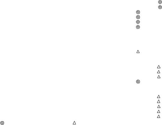
[2] Brazing
No changes from the conventional method, but special care is required so that foreign matter (ie. oxide scale, water, dirt, etc.) does not enter the refrigerant circuit.
Example: Inner state of brazed section
When non-oxide brazing was not used |
When non-oxide brazing was used |
Items to be strictly observed:
1.Do not conduct refrigerant piping work outdoors on a rainy day.
2.Apply non-oxide brazing.
3.Use a brazing material (BCuP-3) which requires no flux when brazing between copper pipes or between a copper pipe and copper coupling.
4.If installed refrigerant pipes are not immediately connected to the equipment, then braze and seal both ends of them.
Reasons:
1.The new refrigerant oil is 10 times more hygroscopic than the conventional oil. The probability of a machine failure if water infiltrates is higher than with conventional refrigerant oil.
2.A flux generally contains chlorine. A residual flux in the refrigerant circuit may generate sludge.
Note:
•Commercially available antioxidants may have adverse effects on the equipment due to its residue, etc. When applying non-oxide brazing, use nitrogen.
- 3 -

[3] Airtightness Test
No changes from the conventional method. Note that a refrigerant leakage detector for R22 cannot detect R407C leakage.
NO NO
Halide torch |
R22 leakage detector |
Items to be strictly observed:
1.Pressurize the equipment with nitrogen up to the design pressure and then judge the equipment’s airtightness, taking temperature variations into account.
2.When investigating leakage locations using a refrigerant, be sure to use R407C.
3.Ensure that R407C is in a liquid state when charging.
Reasons:
1.Use of oxygen as the pressurized gas may cause an explosion.
2.Charging with R407C gas will lead the composition of the remaining refrigerant in the cylinder to change and this
refrigerant can then not be used.
Note:
•A leakage detector for R407C is sold commercially and it should be purchased.
[4]Vacuuming
1.Vacuum pump with check valve
A vacuum pump with a check valve is required to prevent the vacuum pump oil from flowing back into the refrigerant circuit when the vacuum pump power is turned off (power failure).
It is also possible to attach a check valve to the actual vacuum pump afterwards.
2.Standard degree of vacuum for the vacuum pump
Use a pump which reaches 0.5 Torr (500 MICRON) or below after 5 minutes of operation.
In addition, be sure to use a vacuum pump that has been properly maintained and oiled using the specified oil. If the vacuum pump is not properly maintained, the degree of vacuum may be too low.
3.Required accuracy of the vacuum gauge
Use a vacuum gauge that can measure up to 5 Torr. Do not use a general gauge manifold since it cannot measure a vacuum of 5 Torr.
4.Evacuating time
•Evacuate the equipment for 1 hour after –755 mmHg (5 Torr) has been reached.
•After envacuating, leave the equipment for 1 hour and make sure the that vacuum is not lost.
5.Operating procedure when the vacuum pump is stopped
In order to prevent a backflow of the vacuum pump oil, open the relief valve on the vacuum pump side or loosen the charge hose to drawn in air before stopping operation.
The same operating procedure should be used when using a vacuum pump with a check valve.
-4 -
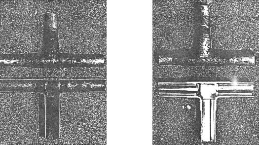
[5] Charging of Refrigerant
R407C must be in a liquid state when charging, because it is a non-azeotropic refrigerant.
For a cylinder with a syphon attached For a cylinder without a syphon attached
|
Cylin- |
Cylin- |
der |
|
|
der |
|
Cylinder color identification R407C-Gray |
Charged with liquid refrigerant |
|
Valve |
R410A-Pink |
Valve |
|
||
Liquid |
|
Liquid |
Reasons:
1.R407C is a mixture of 3 refrigerants, each with a different evaporation temperature. Therefore, if the equipment is charged with R407C gas, then the refrigerant whose evaporation temperature is closest to the outside temperature is charged first while the rest of refrigerants remain in the cylinder.
Note:
•In the case of a cylinder with a syphon, liquid R407C is charged without turning the cylinder up side down. Check the type of cylinder before charging.
- 5 -

2 TYPICAL INSTALLATION EXAMPLE
PRH
3 MODEL-DESIGNATION BREAKDOWN
P R H
Series symbol  Self-contained type (rooftop type)
Heat pump type
Refrigerant
P=R407C
P 1 0 M Y A E U
 Service reference
Design sequence
Series symbol Y=3-phase
380V,400V,415V,50Hz,3N~
Design sequence
Compressor horse power 8=8HP
10=10HP
16=16HP
20=20HP
200=8HP
250=10HP
400=16HP
500=20HP
- 6 -
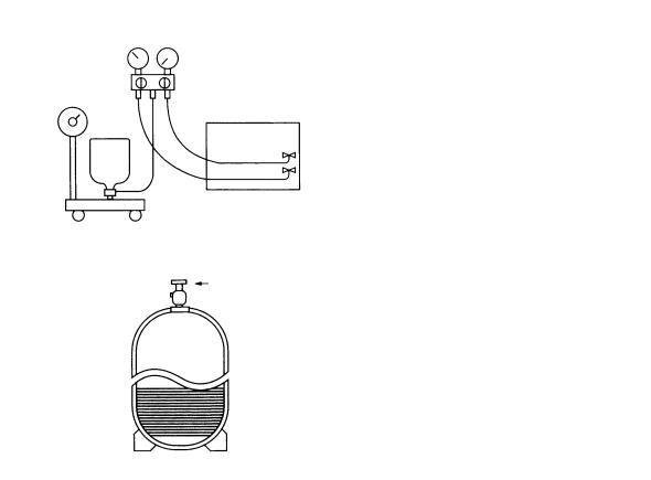
4 PART NAMES AND FUNCTIONS
Unit
Supply air
•Return air : Sucks the ambient air in.
•Supply air : Blows the air back out into the room.
Return air
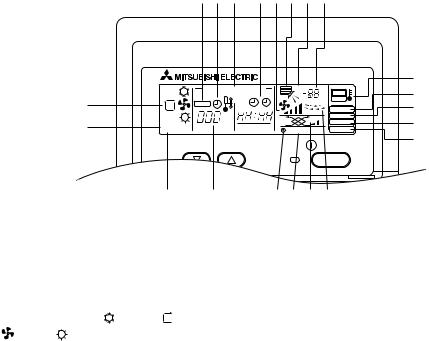
Remote controller PRH-P8, 10, 16, 20MYA (PAR-20MAA)
•Once the controls are set, the same operation mode can be repeated by simply pressing the ON/OFF button.
[Operation buttons]
|
CENTRALLY CONTROLLED |
1Hr. |
|
||
|
|
ON |
OFF |
|
ßC |
|
CHECK |
CLOCK |
|
|
|
|
|
|
|
|
|
|
|
|
|
|
FILTER |
|
ßC |
|
|
|
CHECK MODE |
STAND BY |
ERROR CODE |
|
TEST RUN |
||
|
NOT AVAILABLE |
FUNCTION |
|||
DEFROST |
|
||||
|
|
|
|||
1 |
TEMP. |
|
|
|
ON/OFF |
2 |
|
|
|
|
FILTER |
|
|
|
|
|
|
3 |
|
|
|
|
|
|
|
|
|
|
CHECK TEST |
PAR-20MAA |
TIMER SET |
|
|
|
|
2
1
0
3
4 5 6 8 7 9
1 [Room temperature adjustment] Button
2 [Timer/continuous] Button
3 [Selecting operation] Button
4[Time selection] Button [Time-setting] Button
5 [Louver] Button (This button does not operate in this model)
6 [Fan speed adjustment] Button
7 [Up/down airflow direction] Button (This button does not operate in this model)
8 [Ventilation] Button
9 [Checking/built-in] Button
0[Test run] Button
1[Filter] Button (This button does not operate in this model)
2[ON/OFF] Button
3Position of built-in room temperature
•Never expose the remote controller to direct sunlight. Doing so can result in the erroneous measurement of room temperature.
•Never place any obstacle around the lower right-hand section of the remote controller. Doing so can result in the erroneous measurement of room temperature.
-7 -
[Display]
D C B A U T Q S
E
F
A Current time/Timer |
|
|
C Centralized control |
|
|
D Abnormality control |
|
|
E Operation mode: |
COOL, |
|
FAN, |
HEAT |
|
F Preparing for Heating mode
G Defrost mode
H Set temperature
I Power ON
J Louver
CENTRALLY CONTROLLED
ON OFF
CHECK |
CLOCK |
|
STAND BY |
ßC |
|
ERROR CODE |
||
DEFROST |
||
|
 TEMP.
TEMP.
GH

 AUTO,
AUTO,
|
|
R |
1Hr. |
|
P |
|
ßC |
|
|
FILTER |
O |
|
CHECK MODE |
N |
|
TEST RUN |
|
NOT AVAILABLE |
FUNCTION |
|
M
ON/OFF
I K L J
K Not available function
L Ventilation
M Function setting mode
N Test run mode
O Error check mode
P Filter sign
Q Set effective for 1 hr.
R Sensor position
S Room temperature
T Airflow
U Fan speed
Caution:
•Only the Power display lights when the unit is stopped and power supplied to the unit.
•When power is turned ON for the first time the (CENTRAL CTRL) display appears to go off momentarily but this is not a malfunction.
•When the central control remote control unit, which is sold separately, is used the ON-OFF button, operation switch button and  TEMP. adjustment button do not operate.
•“NOT AVAILABLE” is displayed when the Airflow direction button or Louver button are pressed. This indicates that this room unit is not equipped with the fan direction adjustment function and the louver function.
•When power is turned ON for the first time, it is normal that “H0” is displayed on the room temperature indication (For max. 2 minutes). Please wait until this “H0” indication disappear then start the operation.
- 8 -

PRH-P200, 250, 400, 500MYA (PAR-21MAA)
Remote controller-Button
Opening the door.
1 |
|
|
|
2 |
|
TEMP. |
|
|
|
|
|
|
|
MENU |
ON/OFF |
3 |
BACK |
MONITOR/SET |
DAY |
|
PAR-21MAA |
CLOCK |
|
8
9
ON/OFF
0
|
FILTER |
|
|
CHECK |
A |
|
TEST |
|
OPERATION |
CLEAR |
B |
C
4 5 67
1 |
Set Temperature buttons |
0 Filter |
button (<Enter> button) |
Down |
A Test Run button |
|
|
Up |
B Check button (Clear button) |
|
2 Timer Menu button (Monitor/Set button)
3 Mode button (Return button)
4Set Time buttons
 Back
Back
 Ahead
Ahead
5 Timer On/Off button (Set Day button)
6Louver button ( Operation button)
 To preceding operation number.
7 Ventilation button ( Operation button)
 To next operation number.
8 ON/OFF button
9 Fan Speed button
Remote controller-Display
CAirflow Up/Down button
Notes:
•If you press a button for a feature that is not installed at the indoor unit, the remote controller will display the “Not Available” message.
•If you are using the remote controller to drive multiple indoor units, this message will appear only if the feature is not present at the parent unit.
•Never expose the remote controller to direct sunlight. Doing so can result in the erroneous measurement of room temperature.
•Never place any obstacle around the lower right-hand section of the remote controller. Doing so can result in the erroneous measurement of room temperature.
AB
C |
TIME SUN MON TUE WED THU FRI SAT |
|
||
TIMER |
Hr |
ON |
N |
|
|
AFTER |
AFTER OFF |
||
|
|
|||
|
ERROR CODE |
|
FUNCTION |
|
|
˚F˚C |
|
FILTER |
O |
D |
˚F˚C |
|
||
|
WEEKLY |
P |
||
E |
ONLY1Hr. |
|
SIMPLE |
|
|
AUTO OFF |
|
||
F |
G H I JK L |
M |
|
|
ADay-of-Week
Shows the current day of the week.
Time/Timer Display
Shows the current time, unless the simple or Auto Off timer is set. If the simple or Auto Off timer is set, shows the time remaining.
B“Sensor” indication
Displayed when the remote controller sensor is used.
CIdentifies the current operation
Shows the operating mode, etc.
*Multilanguage display is supported.
D“Centrally Controlled” indicator
Indicates that operation of the remote controller has been prohibited by a main controller.
E“Timer Is Off” indicator
Indicates that the timer is off.
FTemperature Setting
Shows the target temperature.
GUp/Down Air Direction indicator
The indicator  shows the direction of the outcoming airflow.
H “One Hour Only” indicator
K (Power On indicator)
Indicates that the power is on.
LVentilation indicator
Appears when the unit is running in Ventilation mode.
MFan Speed indicator
Shows the selected fan speed.
N“Locked” indicator
Indicates that remote controller buttons have been locked.
O“Clean The Filter” indicator
Comes on when it is time to clean the filter.
PTimer indicators
The indicator comes on if the corresponding timer is set.
Note:
•For purposes of this explanation, all parts of the display are shown as lit. During actual operation, only the relevant items will be lit.
Displayed if the airflow is set to weak and downward during COOL or DRY mode . (Operation varies according to model.)
The indicator goes off after one hour, at which time the airflow direction also changes .
ILouver display
Indicates the action of the swing louver. Does not appear if the louver is stationary.
JRoom Temperature display
Shows the room temperature.
- 9 -

5 SPECIFICATIONS
Specifications of air-source heat pump type packaged air conditioner (Rooftop unit)
Model name |
|
|
PRH-P8MYA/P200MYA |
|
PRH-P10MYA/P250MYA |
||||
Mode |
|
|
Cooling |
|
Heating |
|
Cooling |
|
Heating |
|
|
|
|
|
|
|
|
|
|
Capacity |
|
kW |
20.9 |
|
23.7 |
|
26.0 |
|
30.5 |
|
|
kcal/h |
18,000 |
|
19,000 |
|
22,400 |
|
26,200 |
|
|
Btu/h |
71,430 |
|
75,400 |
|
88,890 |
|
104,000 |
Refrigerant |
|
|
|
|
R407C |
|
|||
|
|
|
|
|
|
|
|
|
|
Power source |
|
|
|
|
3N~ 380/400/415V 50Hz |
|
|||
Electrical |
Power consumption |
kW |
8.12 |
|
8.02 |
|
10.22 |
|
9.82 |
characteristics |
Operating current |
A |
14.7 |
|
14.5 |
|
18.8 |
|
18.2 |
Remote controller temperature setting range |
|
19°C to 30°C |
|
17°C to 28°C |
|
19°C to 30°C |
|
17°C to 28°C |
|
Indoor-side air flow direction |
|
Convertible(Side flow<factory setting> or top flow) |
|||||||
Indoor-side fan |
Type x Quantity |
|
|
|
Sirrocco fan x 2 |
|
|||
|
|
|
|
|
|
|
|
|
|
|
Air flow rate |
CMM |
|
70 |
|
90 |
|
||
|
External static pressure |
Pa |
|
100 |
|
100 |
|
||
|
Motor type |
|
|
|
Three-phase induction motor |
|
|||
|
Motor output |
kW |
|
1.1 |
|
1.5 |
|
||
Indoor-side heat exchanger type |
|
|
|
Cross fin |
|
||||
Outdoor-side fan |
Type x Quantity |
|
|
|
Propeller fan x 1 |
|
|||
|
Air flow rate |
CMM |
|
|
|
185 |
|
|
|
|
Motor type |
|
|
|
Three-phase induction motor |
|
|||
|
|
|
|
|
|
|
|
|
|
|
Motor output |
kW |
|
|
|
0.38 |
|
|
|
Outdoor-side heat exchanger type |
|
|
|
Cross fin |
|
||||
Compressor |
Type |
|
|
|
Hermetic |
|
|||
|
Motor output |
kW |
|
5.5 |
|
7.5 |
|
||
|
Oil type |
|
|
|
FVC68D(ether oil) |
|
|||
|
Crankcase heater |
kW |
|
|
0.05 (240V) |
|
|||
External finish |
|
|
|
Polyester powder (MUNSELL 5Y8/1) |
|
||||
External dimension |
H x W x D |
mm |
|
|
1,715 x 2,000 x 926 |
|
|||
Air filter |
|
|
|
|
Field supplied |
|
|||
Drain pipe Thread |
|
|
|
|
|
R1 |
|
||
Noise level |
|
dB(A) |
|
59 |
|
60 |
|
||
Net weight |
|
kg |
|
407 |
|
412 |
|
||
Protection devices |
|
|
High pressure switch , Low pressure switch , fuse |
|
|||||
|
|
|
Over current relay(compressor , indoor-side fan motor) |
||||||
|
|
|
inner thermal switch in outdoor-side fan motor |
|
|||||
|
|
|
|
|
|
|
|||
|
|
|
|
|
|
|
|
|
|
Note 1. Cooling and Hetaing capacity indicates the maximum value at operation under the following condition. |
|||||||||
Cooling Indoor : 27°CDB/19°CWB Outdoor : 35°CDB |
|
|
|
|
|
|
|||
Heating Indoor : 20°CDB |
Outdoor : 7°CDB/6°CWB |
|
|
|
|
||||
2.The operating noise measuring point is 1m from the bottom of unit (1m from the front of the unit) in an anechoic room. (Noise level is A-scale value)
3.Refrigerant charge volumes are factory charged.
4.The range of working voltage is with in ±10% voltage of power supply.
5.Specification subject to change without notice.
- 10 -

Specifications of air-source heat pump type packaged air conditioner (Rooftop unit)
Model name |
|
|
PRH-P16MYA/P400MYA |
|
PRH-P20MYA/P500MYA |
||||
Mode |
|
|
Cooling |
|
Heating |
|
Cooling |
|
Heating |
|
|
|
|
|
|
|
|
|
|
Capacity |
|
kW |
41.8 |
|
47.4 |
|
52.0 |
|
61.0 |
|
|
kcal/h |
36,000 |
|
40,800 |
|
44,800 |
|
52,400 |
|
|
Btu/h |
142,860 |
|
150,800 |
|
177,780 |
|
208,000 |
Refrigerant |
|
|
|
|
R407C |
|
|||
|
|
|
|
|
|
|
|
|
|
Power source |
|
|
|
|
3N~ 380/400/415V 50Hz |
|
|||
Electrical |
Power consumption |
kW |
16.60 |
|
15.94 |
|
21.44 |
|
19.24 |
characteristics |
Operating current |
A |
29.6 |
|
29.2 |
|
36.6 |
|
35.4 |
Remote controller temperature setting range |
|
19°C to 30°C |
|
17°C to 28°C |
|
19°C to 30°C |
|
17°C to 28°C |
|
Indoor-side air flow direction |
|
Convertible(Side flow<factory setting> or top flow) |
|||||||
Indoor-side fan |
Type x Quantity |
|
|
|
Sirrocco fan x 2 |
|
|||
|
|
|
|
|
|
|
|
|
|
|
Air flow rate |
CMM |
|
140 |
|
180 |
|
||
|
External static pressure |
Pa |
|
200 |
|
200 |
|
||
|
Motor type |
|
|
|
Three-phase induction motor |
|
|||
|
Motor output |
kW |
|
2.2 |
|
3.7 |
|
||
Indoor-side heat exchanger type |
|
|
|
Cross fin |
|
||||
Outdoor-side fan |
Type x Quantity |
|
|
|
Propeller fan x 2 |
|
|||
|
Air flow rate |
CMM |
|
|
185 x 2 |
|
|||
|
Motor type |
|
|
|
Three-phase induction motor |
|
|||
|
|
|
|
|
|
|
|
|
|
|
Motor output |
kW |
|
|
0.38 x 2 |
|
|||
Outdoor-side heat exchanger type |
|
|
|
Cross fin |
|
||||
Compressor |
Type |
|
|
|
Hermetic |
|
|||
|
Motor output |
kW |
5.5 x 2 |
|
7.5 x 2 |
||||
|
Oil type |
|
|
|
FVC68D(ether oil) |
|
|||
|
Crankcase heater |
kW |
|
|
0.05 (240V) x 2 |
|
|||
External finish |
|
|
|
Polyester powder (MUNSELL 5Y8/1) |
|
||||
External dimension |
H x W x D |
mm |
|
|
1,735 x 2,000 x 2,130 |
|
|||
Air filter |
|
|
|
|
Field supplied |
|
|||
Drain pipe Thread |
|
|
|
|
|
R1 |
|
||
Noise level |
|
dB(A) |
|
62 |
|
63 |
|
||
Net weight |
|
kg |
|
857 |
|
872 |
|
||
Protection devices |
|
|
High pressure switch , Low pressure switch , fuse |
|
|||||
|
|
|
Over current relay(compressor , indoor-side fan motor) |
||||||
|
|
|
inner thermal switch in outdoor-side fan motor |
|
|||||
|
|
|
|
|
|
|
|||
|
|
|
|
|
|
|
|
|
|
Note 1. Cooling and Hetaing capacity indicates the maximum value at operation under the following condition. |
|||||||||
Cooling Indoor : 27°CDB/19°CWB Outdoor : 35°CDB |
|
|
|
|
|
|
|||
Heating Indoor : 20°CDB |
Outdoor : 7°CDB/6°CWB |
|
|
|
|
||||
2.The operating noise measuring point is 1m from the bottom of unit (1m from the front of the unit) in an anechoic room. (Noise level is A-scale value)
3.Refrigerant charge volumes are factory charged.
4.The range of working voltage is with in ±10% voltage of power supply.
5.Specification subject to change without notice.
- 11 -
6 ELECTRICAL DATA
VOLT |
|
ITEM |
|
PRH-P8MYA/P200MYA |
PRH-P10MYA/P250MYA |
||
|
|
Cooling |
Heating |
Cooling |
Heating |
||
|
|
|
|
||||
|
TOTAL INPUT |
kW |
8.12 |
8.02 |
10.22 |
9.82 |
|
|
TOTAL RATED CURRENT |
A |
14.7 |
14.5 |
18.8 |
18.2 |
|
|
POWER FACTOR |
% |
76 |
76 |
75 |
75 |
|
|
START CURRENT |
A |
111 |
111 |
134 |
134 |
|
|
COMPRESSOR INPUT |
kW |
6.96 |
6.86 |
8.71 |
8.31 |
|
415V |
RATED CURRENT |
A |
11.9 |
11.7 |
14.9 |
14.3 |
|
|
O/D FAN |
INPUT |
kW |
0.31 |
0.31 |
0.31 |
0.31 |
|
RATED CURRENT |
A |
1.1 |
1.1 |
1.1 |
1.1 |
|
|
I/D FAN |
External static pressure |
Pa |
100 |
100 |
100 |
100 |
|
INPUT |
|
kW |
0.85 |
0.85 |
1.2 |
1.2 |
|
RATED CURRENT |
A |
1.7 |
1.7 |
2.8 |
2.8 |
|
|
|
|
|
|
|
|
|
|
TOTAL INPUT |
kW |
8.12 |
8.02 |
10.22 |
9.82 |
|
|
TOTAL RATED CURRENT |
A |
14.7 |
14.5 |
18.8 |
18.2 |
|
|
POWER FACTOR |
% |
79 |
79 |
78 |
77 |
|
|
START CURRENT |
A |
111 |
111 |
134 |
134 |
|
|
COMPRESSOR INPUT |
kW |
6.96 |
6.86 |
8.71 |
8.31 |
|
400V |
RATED CURRENT |
A |
11.9 |
11.7 |
14.9 |
14.3 |
|
|
O/D FAN |
INPUT |
kW |
0.31 |
0.31 |
0.31 |
0.31 |
|
RATED CURRENT |
A |
1.1 |
1.1 |
1.1 |
1.1 |
|
|
I/D FAN |
External static pressure |
Pa |
100 |
100 |
100 |
100 |
|
INPUT |
|
kW |
0.85 |
0.85 |
1.2 |
1.2 |
|
RATED CURRENT |
A |
1.7 |
1.7 |
2.8 |
2.8 |
|
|
|
|
|
|
|
|
|
|
TOTAL INPUT |
kW |
8.12 |
8.02 |
10.22 |
9.82 |
|
|
TOTAL RATED CURRENT |
A |
14.7 |
14.5 |
18.8 |
18.2 |
|
|
POWER FACTOR |
% |
83 |
84 |
82 |
81 |
|
|
START CURRENT |
A |
111 |
111 |
134 |
134 |
|
|
COMPRESSOR INPUT |
kW |
6.96 |
6.86 |
8.71 |
8.31 |
|
380V |
RATED CURRENT |
A |
11.9 |
11.7 |
14.9 |
14.3 |
|
|
O/D FAN |
INPUT |
kW |
0.31 |
0.31 |
0.31 |
0.31 |
|
RATED CURRENT |
A |
1.1 |
1.1 |
1.1 |
1.1 |
|
|
I/D FAN |
External static pressure |
Pa |
100 |
100 |
100 |
100 |
|
INPUT |
|
kW |
0.85 |
0.85 |
1.2 |
1.2 |
|
RATED CURRENT |
A |
1.7 |
1.7 |
2.8 |
2.8 |
|
|
|
|
|
|
|
||
VOLT |
|
ITEM |
|
PRH-P16MYA/P400MYA |
PRH-P20MYA/P500MYA |
||
|
|
Cooling |
Heating |
Cooling |
Heating |
||
|
|
|
|
||||
|
TOTAL INPUT |
kW |
16.60 |
15.94 |
21.44 |
19.24 |
|
|
TOTAL RATED CURRENT |
A |
29.6 |
29.2 |
36.6 |
35.4 |
|
|
POWER FACTOR |
% |
78 |
75 |
81 |
75 |
|
|
START CURRENT |
A |
126 |
126 |
152 |
151 |
|
|
COMPRESSOR INPUT |
kW |
14.38 |
13.72 |
18.82 |
16.62 |
|
415V |
RATED CURRENT |
A |
23.8 |
23.4 |
29.8 |
28.6 |
|
|
O/D FAN |
INPUT |
kW |
0.62 |
0.62 |
0.62 |
0.62 |
|
RATED CURRENT |
A |
2.2 |
2.2 |
2.2 |
2.2 |
|
|
I/D FAN |
External static pressure |
Pa |
200 |
200 |
200 |
200 |
|
INPUT |
|
kW |
1.6 |
1.6 |
2.0 |
2.0 |
|
RATED CURRENT |
A |
3.6 |
3.6 |
4.6 |
4.6 |
|
|
|
|
|
|
|
|
|
|
TOTAL INPUT |
kW |
16.60 |
15.94 |
21.44 |
19.24 |
|
|
TOTAL RATED CURRENT |
A |
29.6 |
29.2 |
36.6 |
35.4 |
|
|
POWER FACTOR |
% |
80 |
78 |
84 |
78 |
|
|
START CURRENT |
A |
126 |
126 |
152 |
151 |
|
|
COMPRESSOR INPUT |
kW |
14.38 |
13.72 |
18.82 |
16.62 |
|
400V |
RATED CURRENT |
A |
23.8 |
23.4 |
29.8 |
28.6 |
|
|
O/D FAN |
INPUT |
kW |
0.62 |
0.62 |
0.62 |
0.62 |
|
RATED CURRENT |
A |
2.2 |
2.2 |
2.2 |
2.2 |
|
|
I/D FAN |
External static pressure |
Pa |
200 |
200 |
200 |
200 |
|
INPUT |
|
kW |
1.6 |
1.6 |
2.0 |
2.0 |
|
RATED CURRENT |
A |
3.6 |
3.6 |
4.6 |
4.6 |
|
|
|
|
|
|
|
|
|
|
TOTAL INPUT |
kW |
16.60 |
15.94 |
21.44 |
19.24 |
|
|
TOTAL RATED CURRENT |
A |
29.6 |
29.2 |
36.6 |
35.4 |
|
|
POWER FACTOR |
% |
85 |
82 |
89 |
82 |
|
|
START CURRENT |
A |
126 |
126 |
152 |
151 |
|
|
COMPRESSOR INPUT |
kW |
14.38 |
13.72 |
18.82 |
16.62 |
|
380V |
RATED CURRENT |
A |
23.8 |
23.4 |
29.8 |
28.6 |
|
|
O/D FAN |
INPUT |
kW |
0.62 |
0.62 |
0.62 |
0.62 |
|
RATED CURRENT |
A |
2.2 |
2.2 |
2.2 |
2.2 |
|
|
I/D FAN |
External static pressure |
Pa |
200 |
200 |
200 |
200 |
|
INPUT |
|
kW |
1.6 |
1.6 |
2.0 |
2.0 |
|
RATED CURRENT |
A |
3.6 |
3.6 |
4.6 |
4.6 |
|
|
|
|
|
|
|
|
|
- 12 -
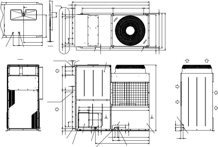
- 13 -
|
|
|
|
2000 |
|
|
Note 3 |
68 |
|
1932 |
|
||
10 |
800 |
800 |
144 |
|||
Y |
|
|||||
50 |
46 |
36.5 |
|
|
|
|
 Y
Y
121
495
155 611
585
6 5
Y-Y
748 5X135Pitch= 675 135
ø 25.4 Knockout hole |
Note 1 |
|
46 |
36.5 |
<Bottom side hole for |
ø 38.1 Knockout hole |
|
||
the controller wiring> |
<Bottom side hole for |
|
|
|
|
the power supply wiring> |
|
|
|
X-X |
|
18- ø 3 Holes 10 |
||
|
|
|||
|
|
|
230 |
15 |
|
|
Supply |
100100 |
|
|
|
|
|
|
|
|
air |
|
|
|
|
|
|
15 |
|
|
|
386 |
10 |
|
|
|
|
|
|
|
|
|
43 |
|
|
28- ø 3 Holes |
910 |
|
|
|
|
995 |
|
|
|
Return |
7X130Pitch= |
|
|
|
air |
|
|
|
|
|
|
130 |
Drain R1
Supply air duct flange
270
250
350
23
185 185
6-14X20 holes Top view <For mounting
anchor bolt M8>
[Field supply]
Service panel
1569
1579
X
Knockout hole
Left side view
60 |
43 |
Return air duct flange
6- ø 3.9 holes (Both side)
Fresh air intake (Both side)
69 |
105 |
95 |
Drain R1
ø 27 hole
<Front side hole for the controller wiring> (Accessory plate)
84 |
149 |
60 |
829 |
165 |
794 |
|
1399 |
Note 2
Front view ø 40 hole
<Front side hole for
the power supply wiring> (Accessory plate)
<Accessory>
•Conduit mounting plate
(Painted the same color as the unit body)
|
15 |
ø 27.................................................. 1pc. |
|
|
ø 34.................................................. |
1pc. |
|
|
|
ø 40 and ø 27................................. 1pc. |
|
|
|
• Tapping screw 4X12........................ 4pcs. |
|
|
|
Note 1. |
It is possible to change to ø 27 or |
840 |
880 |
910 961 |
ø 34 by selecting the conduit |
mounting plate. |
|||
|
|
2. |
The hole size can be selected to |
|
|
|
ø 27 or ø 34 or ø 40 by selecting |
|
|
|
the conduit mounting plate. |
|
|
3. |
These dimension of supply air and |
|
|
|
return air duct flange are the same. |
86 |
15 |
|
|
Air outlet
Air inlet
1715 |
Air inlet |
|
ø 25.4 Knockout hole
X<Right side hole for the controller wiring>
|
60 |
|
|
84 |
|
Service panel |
|
ø 38.1 Knockout hole |
65 |
<Right side hole for |
|
|
the power supply wiring> |
|
|
|
Right side view
• |
7 |
P8MYA/P10MYA/P200MYA/P250MYA-PRH Models |
DIMENSIONS EXTERNAL |
- 14 -
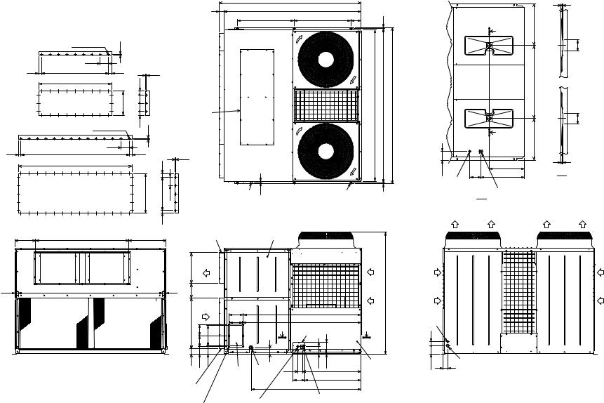
<Accessory> |
|
|
|
|
|
|
|
• Conduit mounting plate |
|
Note 1. It is possible to change to ø40 by |
|
||||
(Painted the same color as |
|
selecting the conduit mounting plate. |
68 |
||||
the unit body) |
|
2. Dimension of supply air and return air |
|||||
|
|
||||||
ø40 |
············ |
1pc. |
duct flange are shown below. |
|
|||
ø52 and ø27 |
············ |
1pc. |
|
|
|
|
|
• Tapping screw 4X12 ············ 4pcs. |
|
|
|
|
|
||
|
24- ø3 Holes |
10 |
|
|
|
|
|
|
|
|
|
|
|
|
|
|
|
150 |
|
|
|
|
|
56 |
8X150Pitch=1200 |
56 |
|
10 |
|
|
|
|
|
|
|
|
|
|
|
|
(1312) |
|
|
67 |
|
|
|
|
|
|
|
|
|
|
|
|
Supply air |
(434) |
150150 |
|
Supply air cover |
|
|
|
duct flange |
|
|
|
|
|
|
|
|
|
|
67 |
|
for top flow |
|
|
|
38- ø3 Holes |
|
|
|
||
|
|
10 |
|
|
|
||
|
|
|
|
|
|
|
|
|
|
|
150 |
|
|
|
|
44 |
13X150Pitch=1950 |
|
44 |
|
10 |
|
|
|
|
|
|
|
|
|
|
|
(2038) |
|
|
|
65 |
|
|
|
|
|
|
|
|
|
|
|
Return air |
|
|
(730) |
4X150Pitch=600 |
150 |
|
|
|
|
|
|
|
|
|
duct flange
23
Drain R1
2000
1932
800 |
800 |
144 |
15
2130 |
2170 |
2200 |
15
6-14X20 holes Top view <For mounting
anchor bolt M10> [Field supply]
111
ø25.4 Knockout hole <Bottom side hole for the controller wiring>
6 5
Y |
585 |
|
50
1030
50
Y
585
6 5
495
155 |
611 |
Y-Y |
Note 1
ø50.8 Knockout hole X-X <Bottom side hole for
the power supply wiring>
|
|
|
65 |
|
|
|
|
Supply air |
|
|
|
|
duct flange |
|
293 |
1312 |
525 |
Note 2 |
Service panel |
Supply
|
|
|
434 |
air |
|
|
|
|
|
|
|
|
|
|
|
|
|
Air |
|
Air |
46 |
2038 |
46 |
202 |
inlet |
1735 |
inlet |
|
|
|
|
|
Return
air
730 |
155 |
290 |
|
155 |
|
80 |
105 |
115 |
Left side view
Return air duct flange Note 2
6- ø3.9 holes (Both side)
200 |
|
1661 |
|
|
180 |
|
1671 |
|
|
|
|
X |
|
|
|
|
Knockout hole |
||
|
89 |
104 |
169 |
|
Fresh air |
Drain |
80 |
839 |
|
R1 |
|
|
||
intake |
165 |
794 |
||
|
||||
(Both side)
1549
ø25.4 Knockout hole <Right side hole for the controller wiring>
X |
|
|
|
80 |
|
Service panel |
104 |
65 |
ø27 hole |
Note 1 |
|
<Front side hole for |
||
ø52 hole |
||
the controller wiring> |
||
<Front side hole for |
||
(Accessory plate) |
||
the power supply wiring> |
||
Front view |
||
(Accessory plate) |
Air |
Air |
outlet |
outlet |
ø50.8 Knockout hole |
|
<Right side hole for |
|
the power supply wiring> |
Right side view |
|
Air inlet
P16MYA/P20MYA/P400MYA/P500MYA-PRH Models •

8 REMOTE CONTROLLER
(Front view) |
(Side view) |
(Rear view) |
120 |
83.5 |
|
|
|
|
|
|
|
|
|
|
|
|
|
130 |
|
19 |
|
|
46 |
|||
|
|
|
|
|
|
|
|
|
|
|
- 15 -
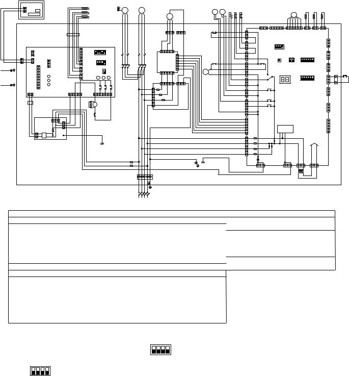
9 ELECTRICAL WIRING DIAGRAM
[1] Unit
• Models PRH-P8MYA/P10MYA
REMOTE CONTROLLER
REMOTE CONTROLLER |
|
|
|
|
|
|
|
|
|
|
BOARD |
|
|
|
TH4 |
|
|
|
PE MF1 |
||
|
CN |
|
|
|
|
|
|
|||
|
|
|
|
TH5 |
|
|
|
|||
TB6 |
LCD |
|
|
|
|
|
|
RED WHITE BLACK |
||
|
|
|
TH6 |
|
|
|
||||
|
|
|
|
|
|
|
|
|||
|
|
|
|
|
FB2 |
|
|
|
|
|
|
INDOOR-SIDE |
|
1 |
5 4 3 2 1 |
|
|
||||
|
1 CONTROLLER BOARD |
2 |
|
|
|
ON |
|
|||
TB5 |
2CN2L |
|
|
3 CN41 |
|
SW1 |
OFF |
51F |
||
|
|
|
|
4 |
|
|
|
|||
1 |
21CN22 |
|
|
|
4 3 2 1 |
|
|
|||
2 |
1 |
|
1 CN29 |
ON |
|
|||||
|
1 |
|
2 CN32 |
2 |
( |
* |
|
OFF |
52F |
|
|
|
3 |
|
1 CN21 |
3)SW2 |
|||||
|
2 |
CN90 |
|
|
|
ON |
|
|||
|
3 |
|
2 |
SWE |
|
|||||
PE |
|
|
|
|
OFF |
|
||||
4 |
|
LED1 |
|
1 |
|
|
|
|
|
|
RETURN AIR |
|
|
|
|
|
|
|
|||
5 |
|
|
2 CN20 |
X4 |
X5 |
X6 |
|
|||
DUCT |
6 |
|
LED2 |
|
|
|
|
|
|
|
|
7 |
|
LED3 |
|
|
|
|
X4 |
X5 |
X6 |
|
8 |
|
|
|
|
|
||||
PE |
9 |
|
|
|
|
|
|
|
|
|
SUPPLY AIR |
2 1 CN2D |
|
5 3 |
1 |
7 |
|
5 |
3 |
1 |
|
DUCT |
DC14V |
|
CN03 |
FAN |
|
|
|
|
|
|
|
FB1 |
|
|
|
CR |
52F |
|
|
|
|
|
|
|
|
|
|
|
|
|
||
|
INDOOR-SIDE |
|
51F |
|
|
|
|
|||
|
POWER BOARD |
|
|
|
|
|
||||
|
|
|
|
|
|
|
|
|||
|
|
CN01 |
1 |
|
|
|
|
|
|
|
|
|
|
1 2 3 |
2 |
|
|
|
|
|
|
|
CN2S |
|
3 |
|
|
|
|
|
|
|
|
F1 |
|
|
|
|
|
|
|
||
|
DC14V |
CN02 |
|
|
|
|
|
|
||
|
1 |
DC |
ZNR |
BK BLACK |
|
|
|
|
|
|
|
2 |
|
|
|
|
|
|
|||
|
|
14V |
|
(WITH INDOOR |
|
|
|
|
|
|
POWER
BOARD)
F2
F1
|
MC |
(*1) |
|
|
|
SV1 |
21S4 |
CH 63H163L |
|
|
|
|
|
TH1 |
TH2 |
TH3 |
|
|
|||||
RED |
WHITE |
BLACK |
|
|
|
|
|
|
|
|
LEV |
|
|
|
|
|
|
|
|
||||
|
MF2 |
|
|
|
|
|
|
|
|
|
|
|
|
|
|
|
|
|
|
||||
|
|
|
|
|
|
|
|
|
|
|
|
|
|
|
|
|
|
|
|
|
|
||
|
|
|
|
|
|
|
|
|
|
|
|
|
|
|
|
2 |
1 |
2 |
1 |
2 |
1 |
|
|
|
|
|
|
1 |
3 |
1 |
3 |
51C |
|
1 |
CN23 |
CNVMNT CNMNT |
|
CN40 |
CN2 |
CN3 |
CN4 |
|
|
||||
|
|
C11 |
|
|
C12 |
|
|
|
|
||||||||||||||
|
|
|
|
|
|
|
|
|
|
|
|
|
|
|
|
|
|
|
|
||||
|
|
|
|
|
|
|
|
|
|
3 |
|
|
|
|
|
|
|
|
|
|
|
|
|
|
|
|
|
|
|
|
|
|
|
1 |
CN22 |
|
|
|
|
|
|
|
|
CN3D |
|
|
|
|
|
|
|
|
|
|
|
|
|
|
1 2 3 4 |
|
|
|
|
|
|
|
|
|
|
||
|
|
|
|
|
|
|
|
|
|
|
|
|
|
|
|
|
|
|
|
|
|
|
|
|
|
|
|
|
|
|
|
|
|
3 |
|
ON |
|
|
|
|
|
|
|
|
|
|
|
|
|
1 |
|
3 |
5 |
|
|
|
|
|
OFF |
|
|
|
|
|
|
|
|
|
|
||
|
|
|
|
|
|
|
|
CN21 |
|
(*2)SW5 |
|
|
|
|
|
|
|
|
|
|
|||
51C |
|
CNFAN |
|
|
1 |
|
|
1 |
|
|
|
|
|
|
|
CN3S |
|
|
|||||
|
|
|
|
|
3 |
|
|
|
|
1 2 |
1 2 3 4 5 6 |
|
|
|
|
|
|||||||
|
|
F.C. |
CNFC2 |
|
|
|
|
|
|
ON |
|
ON |
|
|
|
|
|
|
|
|
|||
|
|
|
|
|
|
|
|
|
|
|
|
|
|
|
|
|
|
||||||
|
|
|
|
|
|
52C |
|
|
CN26 |
X04 |
OFF |
|
OFF |
|
|
|
|
|
|
|
|
||
|
|
BOARD |
|
|
|
|
1 |
SW3 |
SW4 |
SW1 |
|
|
CN3N |
|
|
||||||||
|
|
|
|
|
|
|
|
|
|
|
|
||||||||||||
52C |
|
|
|
|
|
|
|
|
|
|
|
|
|
|
|
|
|||||||
|
|
|
|
|
|
|
|
|
3 |
|
|
|
|
|
|
|
|
|
|
|
|
|
|
|
|
CNPOW |
|
|
6 |
|
|
|
|
|
|
|
|
|
|
|
|
|
|
|
|||
|
|
|
|
52C |
|
|
|
X03 |
|
|
|
|
|
|
|
|
|
|
|
||||
|
|
|
|
|
|
|
|
|
5 |
|
LED1 |
|
|
1 2 3 4 5 6 |
|
|
|
|
63H2 |
||||
|
|
1 |
|
3 |
5 |
|
|
|
|
|
|
|
|
|
|
|
|||||||
|
|
|
|
|
|
|
|
|
|
|
ON |
|
CN24 |
3 |
2 |
||||||||
|
|
|
|
|
|
|
|
CN25 |
|
|
|
|
|
|
|
||||||||
|
|
|
|
|
|
|
|
|
|
1 |
|
|
|
|
|
|
|
|
|
||||
|
|
CNOUT1 1 |
|
3 |
5 |
1 |
3 |
|
|
|
|
|
OFF |
|
|
|
|
|
|
1 |
1 |
||
|
|
|
|
|
3 |
|
|
|
|
|
SW2 |
|
|
|
|
||||||||
|
|
|
|
|
|
|
CNOUT2 |
|
|
|
|
|
|
|
|
|
|
|
|
|
|
C14 |
|
|
|
1 F10 |
|
|
|
|
|
|
|
|
X01 |
|
|
|
|
|
|
|
CN27 |
|
|||
|
|
|
|
|
|
|
|
1 |
CN53 |
|
|
|
|
|
|
|
|
|
|||||
|
|
3 |
F20 |
|
|
|
|
|
3 |
|
|
|
|
|
|
|
|
|
|
|
|
|
|
|
|
|
|
|
|
|
|
|
|
|
|
|
|
|
|
|
|
|
|
|
|
|
|
|
|
5 |
|
F30 |
|
|
|
|
|
1 |
CN52 |
X02 |
OUTDOOR-SIDE |
|
|
|
|
|
|
|
|||
|
|
|
|
|
|
|
|
|
|
|
CONTROLLER BOARD |
|
|
|
|
|
|||||||
|
|
7 |
|
|
|
|
|
|
|
|
|
X05 |
|
CN81 |
|
|
|||||||
|
|
|
|
|
|
|
|
|
|
|
|
|
|
|
|
|
|
|
|
||||
|
|
|
|
|
|
|
|
|
|
|
|
|
|
|
|
|
|
|
|
|
|||
|
|
CNIN |
|
N.F.BOARD |
|
|
|
|
|
|
|
|
|
|
|
|
|
|
|
|
|||
|
|
|
|
|
|
|
|
|
|
5 |
|
|
|
|
|
|
|
|
|
|
|
|
|
|
|
|
|
|
|
|
|
|
|
1 |
CNFC1 |
|
|
|
|
|
|
|
|
CN51 |
|
|
|
|
|
|
|
|
|
|
|
|
|
|
|
|
|
|
|
|
|
|
|
|
|
||
|
|
|
|
|
|
|
|
|
|
|
|
|
TRANSMISSION |
|
|
|
|
|
|
|
|
||
|
|
|
|
|
|
|
|
|
|
6 |
|
|
CIRCIT |
|
|
|
|
|
|
|
|
|
|
|
|
|
|
|
|
|
|
|
|
|
|
|
|
|
|
|
|
|
|
|
|
|
|
|
|
|
|
|
|
|
|
|
|
L1 7 |
CN20 |
|
|
|
|
|
DC POWER |
|
|
||||
|
|
|
|
|
|
|
|
|
|
N 5 |
F01 |
|
|
|
|
|
SUPPLY |
|
|
|
|||
|
|
|
|
|
|
|
|
|
|
|
|
|
|
|
|
|
|
|
|
|
|
|
|
|
|
|
|
|
|
|
|
|
|
L2 3 |
F04 |
|
|
|
|
|
|
|
|
|
|
|
|
|
|
|
|
|
|
|
|
|
|
|
|
|
|
|
|
|
|
|
|
|
|
|
|
|
|
|
|
|
|
|
|
|
|
L3 1 |
F02 |
|
|
|
|
|
|
|
|
|
|
|
|
RED |
WHITE |
BLACK BLUE |
|
|
|
|
|
|
|
|
|
|
|
|
|
|
|
|
|
|
|
|
|
|
GREEN/YELLOW |
|
|
|
F03 |
|
|
|
|
|
|
|
|
|
|
|
|
||||||
|
|
|
|
|
|
|
|
|
|
|
|
|
|
|
|
|
|
|
|||||
|
|
|
|
|
|
|
|
|
|
|
|
|
|
|
|
|
|
|
|
||||
|
|
|
|
|
|
|
|
|
|
|
|
CNFG |
CNS3 |
|
CN28 |
CN34 |
|
|
|
|
|
|
|
|
|
|
|
|
|
|
|
PE |
|
|
3 |
1 |
3 |
1 |
3 |
1 |
3 |
|
1 |
|
|
|
|
|
|
|
|
|
|
|
|
|
|
|
|
|
|
|
|
||||||||
TB1 |
|
|
|
|
|
|
|
|
|
|
|
|
|
|
TR |
|
|
|
|
|
|
|
|
L1 L2 L3 N PE |
|
|
|
|
|
|
|
|
|
|
|
|
|
|
|
|
CONTROL BOX |
||||||
|
|
PE CIRCUIT BREAKER |
|
|
|
|
|
|
|
|
|
|
|
|
|
|
|
|
|
|
|||
|
|
(FIELD SUPPLY) |
|
|
|
|
|
|
|
|
|
|
|
|
|
|
|
|
|
|
|
||
PRH-P8MYA : 63A
PRH-P10MYA: 63A
POWER SUPPLY 3N~PE 380/400/415V 50HZ
Symbol |
Name |
F1,F2 |
FUSE (15A 250VAC CLASS T) |
51C |
OVER CURRENT RELAY (COMPRESSOR) |
52C |
MAGNETIC CONTACTOR (COMPRESSOR) |
63L |
PRESSURE SWITCH (LOW PRESSURE) |
63H1 |
PRESSURE SWITCH (HIGH PRESSURE) |
63H2 |
PRESSURE SWITCH (FOR CONTROL) |
MC |
COMPRESSOR MOTOR |
MF2 |
FAN MOTOR (OUTDOOR-SIDE) |
TR |
TRANSFORMER |
21S4 |
4-WAY VALVE |
SV1 |
SOLENOID VALVE |
CH |
CRANK CASE HEATER (COMPRESSOR) |
LEV |
ELECTRONIC EXPANSION VALVE |
TB1,5 |
TERMINAL BLOCK |
MF1 |
FAN MOTOR (INDOOR-SIDE) |
51F |
OVER CURRENT RELAY (INDOOR-SIDE FAN MOTOR) |
Symbol |
|
|
|
Name |
|
||
52F |
MAGNETIC CONTACTOR (INDOOR-SIDE FAN MOTOR) |
||||||
TH1 |
|
|
|
|
LIQUID PIPE TEMP |
OUT |
|
TH2 |
|
|
|
|
DISCHARGE TEMP |
DOOR |
|
|
|
|
|
|
|
|
-SIDE |
TH3 |
|
|
THERMISTOR |
COND/EVA TEMP |
|||
|
|
|
|||||
TH4 |
|
|
ROOM TEMP |
IN |
|||
|
|
|
|
||||
TH5 |
|
|
|
|
LIQUID PIPE TEMP |
DOOR |
|
|
|
|
|
|
|
|
-SIDE |
TH6 |
|
|
|
|
COND/EVA TEMP |
||
|
|
|
|
|
|||
CR |
|
|
SURGE KILLER |
|
|||
FB1,FB2 |
|
FERRITE CORE |
|
||||
|
|
|
|
|
|
|
|
BOARD |
|
X4-6 |
AUXILIARY RELAY |
|
|||
|
SW1 |
SWITCH (MODEL SELECTION) |
|||||
|
|
||||||
SIDE-INDOOR CONTROLLER |
|
SW2 |
SWITCH (CAPACITY CORD) |
|
|||
|
SWE |
SWITCH (EMERGENCY OPERATION) |
|||||
|
|
||||||
|
|
LED1 |
LED (POWER SUPPLY) |
|
|||
|
|
LED2 |
LED (POWER SUPPLY<REMOTE CONTROLLER>) |
||||
|
|
LED3 |
LED (TRANSMISSION<INDOOR-SIDE·OUTDOOR-SIDE>) |
||||
|
Symbol |
Name |
|||
INDOOR-SIDE |
POWER |
BOARD |
F1 |
FUSE (4A 250VAC CLASS T) |
|
ZNR |
VARISTOR |
||||
|
CONTROLLERBOARD |
F01-F04 |
FUSE (6.3A 250VAC CLASS F) |
||
OUTDOOR-SIDE |
LED1 |
LED (FOR SERVICE) |
|||
SW1-5 |
SWITCH |
||||
|
|
|
X01-X05 |
AUXILIARY RELAY |
|
N.F |
BOARD |
F10-F30 |
FUSE (6.3A 250VAC CLASS F) |
||
|
|
|
|||
|
|
|
|
|
|
|
|
REMOTE CONTROLLER |
|||
|
|
|
|
|
|
|
|
|
Symbol |
Name |
|
|
|
|
|
|
|
|
|
|
TB6 |
TERMINAL BLOCK |
|
Note:1. The dotted lines show field wiring.
2.Color of earth wire is yellow and green twisting.
3.Specification subject to change without notice.
4.This motor(*1) includes auto reset type internal thermostat.
5.SW5(*2)[outdoor-side controller board] is shown PRH-P10MYA setting.
In case of PRH-P8MYA setting is shown as below.
1 2 3 4
ON
OFF [outdoor-side controller board]
(*2) SW5
6.SW2(*3)[indoor-side controller board] is shown PRH-P10MYA setting.
In case of PRH-P8MYA setting is shown as below.
4 3 2 1
ON
OFF [intdoor-side controller board]
(*3) SW2
7.Emergency operation
If a trouble occurs with either the remote controller or the unit microcomputer and no other trouble exists, emergency operation for cooling or heating can be performed by changing the setting of switch (SWE) on the indoor-side controller board.
8. mark is connector.
Caution,
1.To protect compressor and fan motor (indoor-side) from abnormal current, over current relays is installed. Therefore, do not change factory over current relays is installed. Therefore, do not change factory set value of over current relays.
- 16 -
• Models PRH-P16MYA/P20MYA
TH3-1
TH2-1
TH1-1
LEV1
63L1
63H11
CH1
21S41
SV11
MF21
(*1)
BLACK
MC1 WHITERED
BLACK PE MF1 WHITERED
TH4-1 TH5-1 TH6-1
REMOTE CONTROLLER
REMOTE CONTROLLER
BOARD
CN
TB6 LCD
63H21
|
|
|
|
|
|
|
|
|
2 |
|
1 |
|
|
|
|
|
|
|
|
|
|
CONTROL BOX NO.1 |
|||
|
|
|
|
X11 |
|
|
|
|
|
C14 |
|
|
|
|
|
|
|
|
|
||||||
|
|
|
|
|
|
|
|
|
|
|
|
|
|
|
|
|
|
|
|
|
|
|
|
||
|
|
|
|
|
3 |
1 |
|
|
3 |
|
1 |
|
|
|
|
|
|
|
|
|
|
|
|
|
|
1 |
CN4 |
CN3D |
CN3S |
CN3N |
CN24 |
CN27 |
CN81 |
CN51 |
|
|
|
|
|
|
|
|
|||||||||
2 |
|
|
|
|
|
|
|
|
|||||||||||||||||
1 |
|
|
|
|
|
|
|
|
|
|
|
|
|
|
|
|
DC POWER |
|
|
|
1 |
|
|||
CN3 |
|
|
|
|
|
|
|
|
|
|
|
|
|
|
|
|
|
|
|
||||||
2 |
|
|
|
6 |
|
|
6 |
|
|
|
|
|
|
|
|
|
|
|
|
||||||
|
|
|
|
|
|
|
|
|
|
|
|
SUPPLY |
|
|
|
|
|
|
|||||||
1 |
|
|
|
|
|
5 |
|
|
5 |
|
|
|
|
|
|
|
|
|
|
|
|
|
CN34 |
3 |
|
CN2 |
|
|
|
4 |
SW1 |
4 |
|
SW2 |
|
|
|
|
|
|
|
|
|
|
|
||||||
2 |
|
|
|
3 |
3 |
|
|
|
|
|
|
|
|
|
|
|
|
1 |
|
||||||
|
|
|
|
|
|
2 |
|
|
2 |
|
|
|
|
|
|
|
|
|
|
|
|
|
|
|
|
|
|
|
|
|
|
1 |
|
|
1 |
|
|
|
OUTDOOR MAIN BOARD |
|
|
|
|
|
|
|
|
||||
|
|
|
|
|
|
ON OFF |
ON OFF |
|
|
|
|
|
|
|
3 TR1 |
|
|||||||||
|
CN40 |
|
|
|
|
|
|
|
|
|
|
|
|
|
|
CN28 |
|
||||||||
|
|
|
|
2 |
SW4 |
|
|
|
|
|
|
|
|
|
|
|
|
|
|
|
|
|
|||
|
|
|
|
|
|
1 |
|
|
|
|
|
|
|
|
|
|
|
|
|
|
|
1 |
|
||
|
|
|
|
(*2)SW5 ON OFF |
|
|
|
|
|
|
|
|
|
|
|
|
|
|
|
|
|||||
|
|
|
|
|
|
|
|
|
|
|
|
TRANSMISSION |
|
|
|
|
|
|
|
||||||
|
|
|
|
4 |
|
|
|
LED1 |
|
|
|
|
|
|
|
|
|
|
|
CNS3 |
3 |
|
|||
|
|
|
|
3 |
|
|
SW3 |
|
|
|
|
|
|
|
|
CIRCUIT |
|
|
|
|
|
|
|
||
|
CNMNT 12 |
|
|
|
|
|
|
|
|
|
|
|
|
|
|
|
|
|
|
|
|||||
|
|
|
|
ON OFF |
|
|
X03 |
|
X01 |
X02 |
|
X05 |
|
|
|
|
|
|
|
|
|
||||
|
|
|
|
|
|
|
|
|
|
|
|
|
|
|
|
|
|
|
|||||||
|
|
|
|
|
|
|
|
|
|
|
|
|
|
|
|
|
|
CNFG |
|
||||||
|
CNVMNT |
|
|
|
|
|
|
|
|
|
|
|
|
|
|
|
|
|
|
|
|||||
|
|
X04 |
|
|
|
|
|
|
|
|
|
|
|
|
|
|
|
|
1 |
|
|||||
|
|
|
|
|
|
|
|
|
|
|
|
|
|
|
|
|
|
|
|
|
|
|
|||
|
|
|
|
|
|
|
|
|
|
|
|
|
|
|
|
|
|
|
|
|
|
|
|
3 |
|
|
|
CN23 |
|
CN22 |
|
CN21 |
|
CN26 |
|
|
CN25 |
|
CN53 |
|
CN52 |
|
CNFC1 |
|
|
F01 |
F04 |
F02 |
F03 |
|
|
|
|
|
|
|
|
|
|
|
|
|
|
|
|
|
|
|
C18 |
||||||||
|
|
|
|
|
|
|
|
|
|
|
|
|
|
|
|
|
|
|
|
|
|
|
CN20 |
|
|
|
1 |
3 |
1 |
3 |
1 |
3 |
1 |
3 |
5 |
1 |
3 |
1 |
3 |
1 |
3 |
5 6 |
1 |
6 |
7 |
5 |
3 |
1 |
|
1 |
|
|
|
|
|
|
|
|
|
|
|
|
|
|
|
|
|
|
|
|
L1 |
N |
L2 L3 |
|
X11 2 |
||
|
|
|
|
|
|
|
|
|
|
|
|
|
|
|
|
|
|
|
|
|
|
|
|
|
2 |
|
|
|
|
|
|
|
|
|
|
|
|
|
|
|
|
|
|
|
|
|
|
|
|
|
1 |
|
|
|
|
|
|
|
|
|
|
|
|
|
|
|
|
|
|
|
|
|
|
|
|
|
C28 |
51C1 |
|
|
|
|
52C1 |
|
|
|
|
|
|
|
|
|
|
|
|
|
|
|
|
|
|
||
|
|
|
|
|
|
|
|
52C1 |
|
|
|
|
|
|
|
|
|
|
|
|
|
|
|
|
|
|
|
|
|
|
|
|
|
|
|
|
|
|
|
|
|
|
|
|
|
|
|
|
|
PE |
|
|
C12 |
|
|
3 |
CNFAN |
|
CNPOW |
3 |
|
3 |
|
|
F30 |
|
|
|
|
|
|
|
|
GREEN/YELLOW |
|
|
|
|
1 |
|
|
|
|
|
|
|
|
|
|
|
|
|
|
|
|
|
|||||||
|
|
|
|
|
|
|
|
|
|
|
|
CNOUT2 |
|
|
|
|
|
|
|
|
|
|
|
||
|
3 |
|
|
|
|
1 |
|
6 |
|
|
3 |
|
N.F.BOARD |
|
|
|
|
|
|
|
|
|
|||
|
1 |
|
|
|
|
|
|
|
|
|
1 |
CNOUT1 |
|
|
|
|
|
|
|
|
|
|
|
||
|
|
|
|
|
|
CNFC2 |
|
|
|
|
|
|
|
|
|
|
|
|
|
||||||
|
3 |
|
|
|
5 |
|
|
|
5 |
|
5 |
|
|
|
|
|
|
|
|
|
|
|
|
|
|
|
C11 |
|
|
1 |
F.C. |
1 |
|
1 |
F20 |
|
|
|
|
|
|
|
|
|
|
|
|
||||
|
|
|
|
|
BOARD |
|
|
|
|
|
|
|
|
|
|
|
|
|
|
|
|||||
|
|
|
|
|
|
|
|
|
|
|
F10 |
|
|
|
|
|
|
|
|
|
|
|
|
|
|
|
|
|
|
|
|
|
|
52C1 |
|
|
|
1 |
3 |
5 |
7 |
CNIN |
|
|
|
|
|
|
|
PE |
PE |
|
|
|
|
|
51C1 |
|
|
|
|
|
|
|
|
|
|
BLUE |
|
|
|||||||
|
|
|
|
|
|
|
|
|
|
|
|
|
|
|
|
|
|
|
|
N |
N |
||||
|
|
|
|
|
|
|
|
|
|
|
|
|
|
|
|
|
|
|
|
|
|
|
BLACK |
||
|
|
|
|
|
|
|
|
|
|
|
|
|
|
|
|
|
|
|
|
|
|
|
WHITE |
L3 |
L3 |
|
|
|
|
|
|
|
|
|
|
|
|
|
|
|
|
|
|
|
|
|
|
|
RED |
L2 |
L2 |
|
|
|
|
|
|
|
|
52F |
|
|
|
|
CR |
|
|
|
|
|
|
|
|
|
L1 |
L1 |
|
|
|
|
|
RED |
51F |
|
|
|
|
|
|
|
|
|
|
|
|
|
|
TB11 |
TB1 |
||||
|
|
|
|
WHITE |
|
|
|
|
|
|
51F |
|
X2 |
|
|
|
|
|
|
F21 F11 |
RED |
||||
|
|
|
|
BLACK |
|
|
|
|
|
|
|
X1 |
|
|
|
|
|
|
WHITE |
||||||
|
|
|
|
|
|
|
|
|
|
|
|
|
52F |
|
|
|
|
|
|
|
|
||||
|
|
|
|
|
|
|
|
|
|
|
|
|
|
|
|
|
|
|
|
|
BLACK |
||||
|
|
|
|
|
|
|
|
|
|
|
|
|
|
|
|
|
|
|
|
|
|
|
|
|
BLUE |
|
|
|
|
|
|
|
|
|
|
|
|
|
|
|
|
|
|
|
|
|
|
|
|
GREEN/YELLOW |
|
|
|
|
|
|
ON OFF ON OFF ON OFF |
|
X6 |
|
1 |
|
|
|
|
|
|
|
|
|
|
|
|
||||
|
|
|
|
|
X6 |
|
|
|
|
|
|
|
|
|
|
|
|
|
|
|
|||||
|
|
|
|
|
1 |
1 |
|
|
|
X5 |
|
3 |
|
|
|
|
|
|
|
|
|
|
|
|
|
|
|
|
|
|
2 |
2 |
|
SWE X5 |
|
|
|
|
X1 |
|
|
|
|
|
|
|
|
|
|
||
|
|
|
|
|
3 |
3 |
|
X4 |
|
5 |
|
|
|
|
|
|
|
|
|
|
|
||||
44 
5
 X4 7
X4 7
 (*3)SW2
SW1
|
|
|
FAN |
CN41 CN29 CN21 CN20 |
|||
1 2 3 4 |
1 2 |
1 2 |
1 2 |
FB21 |
|
|
1 |
|
|
|
3 |
|
|
|
5 |
TB5 |
INDOOR CONTROLLER CN03 |
1 2 3 CN02 BK |
BLACK |
X2 |
||
1 |
BOARD |
|
|
(WITH INDOOR |
|
|
2 |
|
|
|
3 |
POWER BOARD) |
|
CN32 |
|
|
|
|
||
|
LED1LED2LED3 |
2 |
|
|
||
|
1 2 3 |
|
|
1 |
|
|
|
|
|
|
CN01 F1 ZNR |
|
|
|
|
CN90 |
|
DC14V |
|
|
|
1 2 3 4 5 6 7 8 9 |
CN2D |
CN2S 1 2 |
INDOOR |
|
|
|
CN2L CN22 |
|
|
|||
|
|
DC14V |
|
|||
|
1 2 1 2 |
|
DC14V FB11 |
POWER BOARD |
|
|
|
|
|
1 |
|
|
|
|
|
|
2 |
|
|
|
|
|
PE |
PE |
|
|
|
|
|
RETURN AIR SUPPLY AIR |
|
|
|
|
|
|
DUCT |
DUCT |
|
|
|
63H22
|
|
|
|
|
|
|
|
|
|
2 |
|
1 |
|
|
|
|
|
|
|
|
CONTROL BOX NO.2 |
||||
|
|
|
|
|
X22 |
|
|
|
|
|
|
C14 |
|
|
|
|
|
|
|
||||||
|
|
|
|
|
1 |
|
|
3 |
|
1 |
|
|
|
|
|
|
|
|
|
|
|
|
|
||
|
|
|
|
|
|
3 |
|
|
|
|
|
|
|
|
|
|
|
|
|
|
|
|
|||
|
1 |
CN4 |
CN3D |
CN3S |
|
CN3N |
CN24 |
CN27 |
|
CN81 |
|
CN51 |
|
|
|
|
|
|
|||||||
|
2 |
|
|
|
|
|
|
|
|
|
|||||||||||||||
TH3-2 |
1 |
CN3 |
|
|
|
|
|
|
|
|
|
|
|
|
|
|
|
DC POWER |
|
|
|
1 |
|||
|
2 |
|
|
|
6 |
|
|
6 |
|
|
|
|
|
|
|
|
|
|
|
|
|||||
|
|
|
|
|
|
|
|
|
|
|
|
|
|
SUPPLY |
|
|
|
|
|
||||||
TH2-2 |
1 |
|
|
|
|
|
5 |
|
|
5 |
|
|
|
|
|
|
|
|
|
|
|
|
|
CN34 |
3 |
|
2 |
CN2 |
|
|
|
4 |
|
SW1 |
4 |
|
SW2 |
|
|
|
|
|
|
|
|
|
|
|
|||
|
|
|
|
3 |
|
3 |
|
|
|
|
|
|
|
|
|
|
|
|
1 |
||||||
TH1-2 |
|
|
|
|
|
|
2 |
|
|
2 |
|
|
|
|
|
|
|
|
|
|
|
|
|
|
|
|
|
|
|
|
|
|
1 |
|
|
1 |
|
|
|
OUTDOOR MAIN BOARD |
|
|
|
|
|
|
|||||
|
|
|
|
|
|
|
ON OFF |
ON OFF |
|
|
|
|
|
CN28 3 TR2 |
|||||||||||
LEV2 |
|
CN40 |
|
|
|
|
|
|
|
|
|
|
|
|
|
|
|||||||||
|
|
|
|
2 |
|
SW4 |
|
|
|
|
|
|
|
|
|
|
|
|
|
|
|
|
|||
|
|
|
|
|
|
|
1 |
|
|
|
|
|
|
|
|
|
|
|
|
|
|
|
|
1 |
|
|
|
|
|
(*2)SW5 |
ON OFF |
|
|
|
|
|
|
|
|
|
|
|
|
|
|
|
|||||
|
|
|
|
|
|
|
|
|
|
|
|
|
|
|
|
|
|
|
|
||||||
|
|
|
|
|
4 |
|
|
|
LED1 |
|
|
|
|
|
|
|
TRANSMISSION |
|
|
|
|
CNS3 |
3 |
||
|
|
|
|
|
3 |
|
|
|
SW3 |
|
|
|
|
|
|
|
|
CIRCUIT |
|
|
|
|
|
||
|
|
CNMNT 12 |
|
|
|
|
|
|
|
|
|
|
|
|
|
|
|
|
|
|
|
||||
|
|
|
|
|
ON OFF |
|
|
X03 |
|
X01 |
X02 |
|
X05 |
|
|
|
|
|
|
|
|
||||
|
|
|
|
|
|
|
|
|
|
|
|
|
|
|
|
|
CNFG |
|
|||||||
|
|
CNVMNT |
|
|
|
|
|
|
|
|
|
|
|
|
|
|
|
|
|
|
|
||||
|
|
|
|
X04 |
|
|
|
|
|
|
|
|
|
|
|
|
|
|
|
|
1 |
||||
|
|
|
|
|
|
|
|
|
|
|
|
|
|
|
|
|
|
|
|
|
|
|
|
||
|
|
|
|
|
|
|
|
|
|
|
|
|
|
|
|
|
|
|
|
|
|
|
|
|
3 |
|
|
|
CN23 |
|
CN22 |
|
CN21 |
|
CN26 |
|
|
CN25 |
|
CN53 |
|
CN52 |
|
|
CNFC1 |
|
F01 |
F04 |
F02 |
F03 |
|
|
|
|
|
|
|
|
|
|
|
|
|
|
|
|
|
|
|
||||||||
63L2 |
|
1 |
3 |
1 |
3 |
1 |
3 |
1 |
3 |
5 |
1 |
3 |
1 |
3 |
1 |
3 |
5 6 |
1 |
6 |
7 |
5 |
3 |
1 |
CN20 |
|
|
|
|
|
|
|
|
|
|
|
|
|
|
|
|
|
|
|
|
L1 |
N |
L2 L3 |
|
|
||
|
|
|
|
|
|
|
|
|
|
|
|
|
|
|
|
|
|
|
|
|
|
||||
63H12
CH2
21S42
CIRCUIT BREAKER (FIELD SUPPLY) PRH-P16MYA: 63A PRH-P20MYA: 70A
PE
POWER SUPPLY 3N~PE 380/400/415V 50HZ
SV12 |
|
51C2 |
|
52C2 |
|
|
|
|
|
|
|
|
|
|
C28 |
|
|
52C2 |
|
|
|
|
|
|
|
|
|
|
|
|
|
|
|
|
|
|
|
|
|
|
1 |
|
|
|
|
|
|
|
|
|
|
|
|
2 |
|
|
|
|
|
|
|
|
|
|
|
|
2 |
|
|
|
|
|
|
|
|
PE |
|
|
|
1 |
X22 |
|
|
|
|
|
|
|
|
|
|
|
C18 |
|
|
|
|
|
|
|
GREEN/YELLOW |
|
|
|
|
C12 |
|
|
|
|
|
1 |
|
|
|
|
|
|
|
|
|
|
|
|
CNOUT2 |
|
|
|
|
|
|
3 |
|
1 |
6 |
|
|
3 |
N.F.BOARD |
|
|
|
|
|
1 |
|
|
|
|
|
|
|
|||
|
|
|
|
|
|
|
CNOUT1 |
|
|
|
||
|
|
|
|
CNFC2 |
|
|
|
|
|
|||
|
|
3 |
5 |
5 |
|
5 |
|
|
|
|
||
MF22 |
CNFAN |
|
|
|
|
|
|
|||||
(*1) |
|
1 |
3 |
CNPOW |
3 |
|
3 |
F30 |
|
|
|
|
|
|
C11 |
1 |
F.C. |
|
1 |
|
1 |
F20 |
|
|
|
|
|
|
BOARD |
|
|
|
|
|
||||
|
|
|
|
|
|
|
|
F10 |
|
|
|
|
|
|
|
|
51C2 |
52C2 |
|
|
1 |
3 5 7 CNIN |
BLUE |
|
PE |
|
BLACK |
|
|
|
|
|
|
BLACK |
N |
|||
|
|
|
|
|
|
|
|
|
||||
MC2 |
WHITE |
|
|
|
|
|
|
|
|
WHITE |
L3 |
|
RED |
|
|
|
|
|
|
|
|
RED |
|
L2 |
|
|
|
|
|
|
|
|
|
|
|
|
|
L1 |
|
|
|
|
|
|
|
|
|
|
|
|
TB21 |
|
|
|
|
|
|
|
|
X6 |
1 |
F22 |
F12 |
|
|
|
|
ON OFF ON OFF ON OFF |
|
|
|
|
|||||
|
|
|
X6 |
|
|
|
|
|
||||
|
|
|
1 |
1 |
|
|
X5 |
3 |
|
|
|
|
|
|
|
2 |
2 |
SWE |
|
X5 |
|
|
|
|
|
|
|
|
3 |
3 |
|
X4 |
5 |
|
|
|
||
44
5X4 7
(*3)SW2
TH4-2 |
TH5-2 TH6-2 |
SW1 |
|
|
FAN |
|
|
|
|||
|
|
CN41 CN29 CN21 CN20 |
|||
|
|
1 2 3 4 |
1 2 |
1 2 |
1 2 |
|
|
FB22 |
|
|
1 |
|
|
|
|
|
3 |
|
|
|
|
|
5 |
C19 |
|
CN03 |
|
|
|
BLACK |
1 |
INDOOR CONTROLLER |
1 2 3 CN02 |
BK (WITH INDOOR |
|||
3 |
BOARD |
|
||||
|
|
3 |
|
|
POWER BOARD) |
|
|
CN32 |
|
|
|
|
|
|
LED1 LED2 LED3 |
2 |
|
|
|
|
|
1 2 3 |
|
1 |
|
|
|
|
|
|
CN01 F1 |
ZNR |
|
|
|
|
CN90 |
|
DC14V |
|
|
|
1 2 3 4 5 6 7 8 9 |
CN2S |
1 |
2 |
|
|
|
CN2L CN22 |
CN2D |
INDOOR |
|||
|
DC14V |
|
|
|||
|
1 2 1 2 |
DC14V FB12 |
|
|
POWER BOARD |
|
|
|
1 |
|
|
|
|
|
|
2 |
|
|
|
|
Symbol |
Name |
F11,12,21,22 |
FUSE (15A 250VAC CLASS T) |
51C1,51C2 |
OVER CURRENT RELAY (COMPRESSOR) |
52C1,52C2 |
MAGNETIC CONTACTOR (COMPRESSOR) |
63L1,63L2 |
PRESSURE SWITCH (LOW PRESSURE) |
63H11,63H12 |
PRESSURE SWITCH (HIGH PRESSURE) |
63H21,63H22 |
PRESSURE SWITCH (FOR CONTROL) |
MC1,MC2 |
COMPRESSOR MOTOR |
MF21,MF22 |
FAN MOTOR (OUTDOOR) |
TR1,TR2 |
TRANSFORMER |
21S41,21S42 |
4-WAY VALVE |
SV11,SV12 |
SOLENOID VALVE |
CH1,CH2 |
CRANK CASE HEATER (COMPRESSOR) |
LEV1,LEV2 |
ELECTRONIC EXPANSION VALVE |
TB1,5,11,21 |
TERMINAL BLOCK |
MF1 |
FAN MOTOR (INDOOR) |
51F |
OVER CURRENT RELAY (INDOOR FAN MOTOR) |
|
|
Symbol |
|
|
Name |
|
||
52F |
|
MAGNETIC CONTACTOR (INDOOR FAN MOTOR) |
||||
TH1-1,TH1-2 |
|
|
LIQUID PIPE TEMP |
OUT |
||
TH2-1,TH2-2 |
|
|
DISCHARGE TEMP |
|||
|
|
DOOR |
||||
TH3-1,TH3-2 |
THERMISTOR |
COND/EVA TEMP |
||||
|
||||||
TH4-1,TH4-2 |
ROOM TEMP |
IN |
||||
|
|
|||||
TH5-1,TH5-2 |
|
|
LIQUID PIPE TEMP |
|||
|
|
DOOR |
||||
TH6-1,TH6-2 |
|
|
COND/EVA TEMP |
|||
|
|
|
||||
CR |
|
SURGE KILLER |
|
|||
FB11,12,21,22 |
FERRITE CORE |
|
||||
|
|
|
|
|
|
|
BOARD |
X4-6 |
AUXILIARY RELAY |
|
|||
SW1 |
SWITCH (MODEL SELECTION) |
|||||
SW2 |
SWITCH (CAPACITY CORD) |
|
||||
INDOOR CONTROLLER |
|
|||||
SWE |
SWITCH (EMERGENCY OPERATION) |
|||||
LED1 |
LED (POWER SUPPLY) |
|
||||
LED2 |
LED (POWER SUPPLY<REMOTE CONTROLLER>) |
|||||
LED3 |
LED (TRANSMISSION<INDOOR·OUTDOOR>) |
|||||
|
||||||
Symbol |
Name |
|||
INDOOR POWER |
BOARD |
ZNR |
VARISTOR |
|
|
|
|
F1 |
FUSE (4A 250VAC CLASS T) |
OUTDOOR BOARDMAIN |
|
|
SWITCH |
|
SW1-5 |
||||
|
|
F01-F04 |
FUSE (6.3A 250VAC CLASS F) |
|
|
|
LED1 |
LED (FOR SERVICE) |
|
|
|
X01-X05 |
AUXILIARY RELAY |
|
N.F BOARD |
F10-F30 |
FUSE (6.3A 250VAC CLASS F) |
||
|
|
|
|
|
|
REMOTE CONTROLLER |
|||
|
|
|
|
|
|
|
Symbol |
Name |
|
|
|
|
|
|
|
|
TB6 |
TERMINAL BLOCK |
|
Note:1. The dotted lines show field wiring.
2.Color of earth wire is yellow and green twisting.
3.Specification subject to change without notice.
4.This motor(*1) includes auto reset type internal thermostat.
5.SW5(*2)[outdoor main board] shows PRH-P20MYA setting. In case of PRH-P16MYA setting is shown as below.
Control box no.1 1 2 3 4
(*2) SW5 |
|
|
|
|
|
ON |
[outdoor main board] |
|
|
|
|
|
OFF |
||
|
|
|
|
|
|
||
|
|
|
|
|
|
|
|
Control box no.2 |
|
||||||
1 |
2 |
3 |
4 |
|
|
|
|
(*2) SW5 |
|
|
|
|
|
ON |
[outdoor main board] |
|
|
|
|
|
OFF |
||
|
|
|
|
|
|
|
|
6.SW2(*3)[indoor controller board] shows PRH-P20MYA setting.
In case of PRH-P16MYA setting is shown as below.
4 3 2 1
ON
OFF [intdoor controller board]
(*3) SW2
7.Emergency operation
If a trouble occurs with either the remote controller or the unit microcomputer and no other trouble exists, emergency operation for cooling or heating can be performed by changing the setting of switch (SWE) on the indoor controller board.
8. mark is connector.
Caution,
1.To protect compressor and fan motor (indoor) from abnormal current, over current relays is installed. Therefore, do not change factory set value of over current relays.
- 17 -
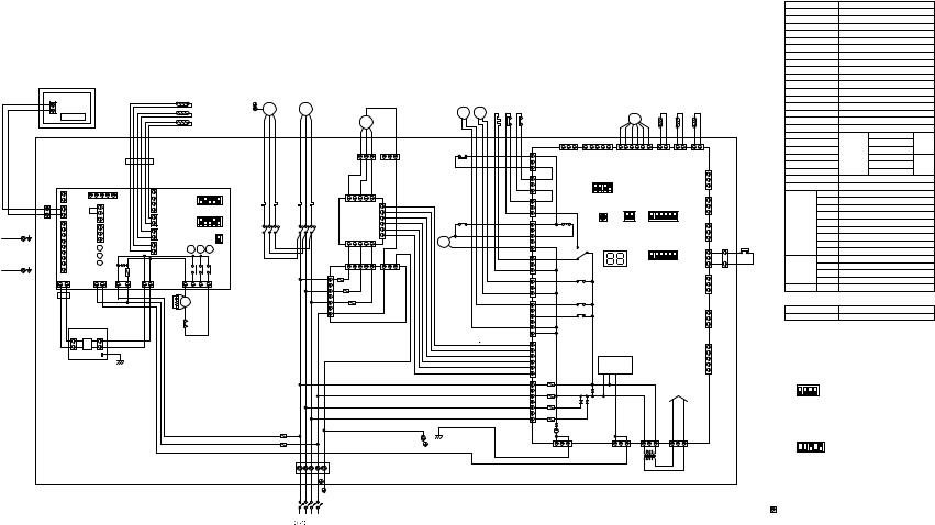
- 18 -
REMOTE CONTROLLER
REMOTE CONTROLLER
|
BOARD |
|
|
|
|
|
|
|
|
TH4 |
|
|
|
|
|
|
||
|
|
|
|
|
|
|
|
|
|
|
|
|
|
|
|
|
|
|
|
TB6 |
|
LCD |
|
|
|
|
|
|
|
|
TH5 |
|
|
|
|
|
|
|
|
|
|
|
|
|
|
|
|
TH6 |
|
|
|
|
|
|
||
|
|
|
|
|
|
|
|
|
|
|
|
|
|
|
|
|
|
|
|
|
|
|
|
|
|
|
|
FB2 |
|
|
|
|
|
|
|
|
|
|
|
INDOOR |
|
|
|
|
|
|
|
|
|
|
|
|
|
|
|
|
|
CONTROLLER BOARD |
|
|
|
|
|
|
|
|
|
|
|
|
|
||||
|
|
21 |
|
5 |
4 |
3 |
2 |
4 |
1 |
|
|
1 2 3 4 5 |
|
|||||
|
|
CN2L |
|
|
|
|
|
|
|
ON |
||||||||
|
TB5 |
|
|
|
CN51 |
2 |
CN41 |
|
||||||||||
|
|
|
|
|
|
3 |
|
|
|
|
|
|
|
OFF |
||||
|
1 |
1 |
CN22 |
|
|
1 |
|
|
4 |
|
|
|
|
|
SW1 |
|
|
|
|
2 |
|
|
|
CN31 |
|
|
1 |
2 |
5 |
|
|||||||
|
2 |
|
|
2 |
|
1 |
CN29 |
|
3 |
4 |
ON |
|||||||
|
|
|
|
|
|
3 |
|
|
|
|
|
|
|
|
|
|||
|
|
1 |
|
|
|
1 |
|
|
2 |
|
|
(*3)SW2 |
|
|
OFF |
|||
|
|
3 |
|
|
|
|
CN32 |
1 |
CN21 |
|
|
|
|
|
||||
|
|
|
|
|
2 |
|
|
|
|
|
|
|||||||
|
|
2 |
|
|
|
|
|
|
|
|
|
|
|
|
|
|
|
|
|
|
|
|
|
|
3 |
|
|
2 |
|
|
|
|
|
SWE |
|
ON |
|
PE |
|
4 |
CN90 |
|
|
|
|
1 |
|
|
|
|
|
|
OFF |
|||
|
5 |
|
|
LED1 |
CN20 |
X4 |
X5 |
|
X6 |
|
|
|
||||||
RETURN AIR |
|
6 |
|
|
|
LED2 |
2 |
|
|
|
|
|
|
|
|
|
||
DUCT |
|
7 |
|
|
|
|
|
|
|
|
|
|
|
|
|
|||
|
|
|
|
LED3 ZNR |
|
|
|
X4 |
X5 |
X6 |
|
|
||||||
|
|
8 |
|
|
|
|
|
|
|
|
||||||||
PE |
|
9 |
|
|
CN3C |
|
FUSE |
|
|
|
|
|
|
|
|
|
|
|
|
|
|
|
|
|
|
|
|
|
|
|
|
|
|
|
|||
2 |
1 |
CN2D |
|
3 |
1 |
|
3 1 |
3 1 |
|
7 |
5 |
3 |
|
1 |
|
|
|
|
SUPPLY AIR |
|
|
|
|
FAN |
|
||||||||||||
|
|
DC13.1V |
|
|
|
|
CND |
CNDK |
|
|
|
|
|
|
||||
DUCT |
|
|
FB1 |
|
|
|
|
|
|
|
|
|
|
|
|
|
|
|
|
|
|
|
|
|
|
|
|
CR |
52F |
|
|
|
|
|
|
|
|
|
|
|
|
|
|
|
|
|
|
|
|
|
|
|
|
|
||
|
|
|
INDOOR |
|
|
|
|
|
|
|
|
|
|
|
|
|
|
|
|
|
|
POWER BOARD |
|
|
|
|
|
51F |
|
|
|
|
|
|
|
||
|
|
|
CN2S |
|
CNSK |
|
|
|
|
|
|
|
|
|
|
|
|
|
|
|
|
1 |
DC |
|
1 |
|
|
|
|
|
|
|
|
|
|
|
|
|
|
|
2 |
|
3 |
|
|
|
|
|
|
|
|
|
|
|
|
|
|
|
|
13.1V |
|
|
|
|
|
|
|
|
|
|
|
|
|
||
|
|
|
|
|
|
|
|
|
|
|
|
|
|
|
|
|
|
|
|
|
|
|
TAB1 |
|
|
|
|
|
|
|
|
|
|
|
|
|
|
PE MF1
BLACK
WHITE
RED
51F
52F
F2
F1
|
MC |
|
(*1) |
|
|
|
SV1 |
21S4 |
CH 63H1 63L |
|
|
|
|
|
|
|
|
|
|
|
|
|
|||
|
WHITE |
BLACK |
|
|
MF2 |
|
|
|
|
|
|
|
RED |
|
|
|
|
|
|
|
|
|
|
||
|
|
|
|
1 |
3 |
1 |
3 |
51C |
|
|
1 |
CN23 |
|
|
|
|
C11 |
|
|
C12 |
|
|
|
|
|
|
|
|
|
|
|
|
|
|
|
|
3 |
|
|
|
|
|
|
|
|
|
|
|
|
1 |
CN22 |
|
|
|
1 |
3 |
5 |
|
|
|
|
|
3 |
|
|
|
|
|
|
|
|
|
|
CN21 |
|||
51C |
|
|
CNFAN |
|
|
1 |
|
|
|
1 |
||
|
|
|
|
|
|
|
3 |
|
||||
|
|
|
F.C. |
|
CNFC2 |
|
|
|
|
|
|
|
|
|
|
|
|
|
52C |
|
|
|
CN26 |
||
|
|
|
BOARD |
|
|
|
|
|
1 |
|||
52C |
|
|
|
|
|
|
|
|
||||
|
|
|
|
|
|
|
|
|
|
3 |
|
|
|
|
|
CNPOW |
|
|
6 |
|
|
|
|
||
|
|
|
|
|
52C |
|
|
|
|
|||
|
|
|
|
|
|
|
|
|
|
5 |
|
|
|
|
|
1 |
3 |
5 |
|
|
|
|
|
|
|
|
|
|
|
|
|
|
|
|
CN25 |
|||
|
|
|
CNOUT1 1 |
3 |
5 |
1 |
3 |
|
|
|
1 |
|
|
|
|
|
|
|
|
|
|||||
|
|
|
|
|
|
|
CNOUT2 |
|
|
|
3 |
|
|
|
1 |
F10 |
|
|
|
|
|
|
1 |
CN53 |
|
|
|
|
|
|
|
|
|
|
|
|||
|
|
3 |
|
F20 |
|
|
|
|
|
|
3 |
|
|
|
|
|
|
|
|
|
|
|
|
|
|
|
|
5 |
|
F30 |
|
|
|
|
|
|
1 |
CN52 |
|
|
|
|
|
|
|
|
|
|
|
||
|
|
7 |
|
|
|
|
|
|
|
|
|
|
|
|
|
CNIN |
|
|
N.F.BOARD |
|
|
|
|
|
|
|
|
|
|
|
|
|
|
|
|
|
5 |
|
|
|
|
|
|
|
|
|
|
|
|
1 |
CNFC1 |
|
|
|
|
|
|
|
|
|
|
|
6 |
|
|
|
|
|
|
|
|
|
|
|
L1 |
7 |
CN20 |
|
|
|
|
|
|
|
|
|
|
N |
5 |
F01 |
|
|
|
|
|
|
|
|
|
|
|
||
|
|
|
|
|
|
|
|
|
|
L2 |
3 |
F04 |
|
|
|
|
|
|
|
|
|
|
|
||
|
|
|
|
|
|
|
|
|
|
L3 |
1 |
F02 |
|
|
|
|
|
|
|
|
|
|
|
||
RED |
WHITE |
BLACK BLUE |
|
GREEN/YELLOW |
|
|
|
|
|
|
F03 |
|
|
|
|
|
|
|
|
|
|||||
PE
TB1
L1 L2 L3 N PE
PE CIRCUIT BREAKER
(FIELD SUPPLY) PRH-P200MYA : 50A PRH-P250MYA : 50A
POWER SUPPLY
380/400/415V
50HZ
TH1 TH2 TH3
LEV
|
|
|
|
|
|
|
|
|
2 |
|
1 |
|
2 |
1 |
2 |
1 |
|
|
|
CNVMNT |
CNMNT |
|
|
|
CN40 |
|
|
CN2 |
|
|
CN3 |
|
CN4 |
|
|
||
|
|
|
|
|
|
|
|
|
|
|
|
|
|
|
|
CN3D |
|
|
|
|
1 |
2 |
3 |
4 |
|
|
|
|
|
|
|
|
|
|
|
|
|
|
|
ON |
|
|
|
|
|
|
|
|
|
|
|
|
|
|
|
|
|
|
OFF |
|
|
|
|
|
|
|
|
|
|
|
|
|
|
|
|
|
|
(*2)SW5 |
|
|
|
|
|
|
|
|
|
|
|
CN3S |
|
|
||
|
|
|
|
|
|
|
|
|
|
|
|
|
|
|
|
|
|
|
|
|
|
|
|
|
1 |
2 |
1 |
2 |
3 |
4 |
5 |
6 |
|
|
|
|
|
|
X04 |
|
|
|
|
ON |
|
ON |
|
|
|
|
|
|
|
|
|
|
|
|
SW3 |
|
OFF |
|
OFF |
|
|
|
|
|
|
|
|
|
|
||
|
|
|
|
SW4 |
|
|
SW1 |
|
|
|
|
CN3N |
|
|
||||
|
|
X03 |
|
LED1 |
|
|
1 |
2 |
3 |
4 |
5 |
6 |
|
|
|
3 |
2 |
|
|
|
|
|
|
|
|
|
CN24 |
||||||||||
|
|
|
|
|
|
|
|
ON |
|
|
|
|
|
|
|
|||
|
|
|
|
|
|
|
|
OFF |
|
SW2 |
|
|
|
|
|
1 |
1 |
|
|
|
|
|
|
|
|
|
|
|
|
|
|
|
|
||||
|
|
|
|
|
|
|
|
|
|
|
|
|
|
|
|
|
||
|
|
X01 |
|
|
|
|
|
|
|
|
|
|
|
|
|
CN27 |
|
C14 |
|
|
|
|
|
|
|
|
|
|
|
|
|
|
|
|
|
||
|
|
X02 |
|
|
|
OUTDOOR MAIN BOARD |
|
|
|
|
|
|
|
|||||
|
|
X05 |
|
|
|
|
|
|
|
|
|
|
|
|
|
CN81 |
|
|
|
|
|
|
|
|
|
|
|
|
|
|
|
|
|
|
CN51 |
|
|
|
|
|
TRANSMISSION |
|
|
|
|
|
|
|
|
|
|
|
|
|||
|
|
|
|
CIRCIT |
|
|
|
|
|
|
|
|
|
|
|
|
|
|
|
|
|
|
|
|
|
|
|
|
|
|
DC POWER |
|
|
|
|||
|
|
|
|
|
|
|
|
|
|
|
|
SUPPLY |
|
|
|
|
||
|
CNFG |
|
CNS3 |
|
|
CN28 |
|
CN34 |
|
|
|
|
|
|
||||
3 |
1 |
|
|
|
3 |
1 |
|
3 |
1 |
|
|
3 |
|
|
1 |
|
|
|
|
|
|
|
|
|
|
|
TR |
|
|
|
|
|
|
|
|
|
|
CONTROL BOX
SYMBOL |
NAME |
|
|
F1,F2 |
|
FUSE (15A 250VAC CLASS T) |
|
51C |
|
OVER CURRENT RELAY (COMPRESSOR) |
|
52C |
|
MAGNETIC CONTACTOR (COMPRESSOR) |
|
63L |
|
PRESSURE SWITCH (LOW PRESSURE) |
|
63H1 |
|
PRESSURE SWITCH (HIGH PRESSURE) |
|
63H2 |
|
PRESSURE SWITCH (FOR CONTROL) |
|
MC |
|
COMPRESSOR MOTOR |
|
MF2 |
|
FAN MOTOR (OUTDOOR) |
|
TR |
|
TRANSFORMER |
|
21S4 |
|
4-WAY VALVE |
|
SV1 |
|
SOLENOID VALVE |
|
CH |
|
CRANK CASE HEATER (COMPRESSOR) |
|
LEV |
|
ELECTRONIC EXPANSION VALVE |
|
TB1,5 |
|
TERMINAL BLOCK |
|
MF1 |
|
FAN MOTOR (INDOOR) |
|
51F |
|
OVER CURRENT RELAY (INDOOR FAN MOTOR) |
|
52F |
|
MAGNETIC CONTACTOR (INDOOR FAN MOTOR) |
|
TH1 |
|
LIQUID PIPE TEMP |
|
TH2 |
|
DISCHARGE TEMP |
OUTDOOR |
TH3 |
|
THERMISTOR COND/EVA TEMP |
|
TH4 |
|
ROOM TEMP |
|
TH5 |
|
LIQUID PIPE TEMP |
INDOOR |
TH6 |
|
COND/EVA TEMP |
|
CR |
|
SURGE KILLER |
|
FB1,FB2 |
FERRITE CORE |
|
|
INDOOR |
X4-6 |
AUXILIARY RELAY |
|
CONTROLLER |
SW1 |
SWITCH (MODEL SELECTION) |
|
BOARD |
SW2 |
SWITCH (CAPACITY CORD) |
|
|
SWE |
SWITCH (EMERGENCY OPERATION) |
|
|
LED1 |
LED (POWER SUPPLY) |
|
|
LED2 |
LED (POWER SUPPLY<REMOTE CONTROLLER>) |
|
|
LED3 |
LED (TRANSMISSION<INDOOR.OUTDOOR>) |
|
63H2 |
ZNR |
VARISTOR |
|
|
FUSE |
FUSE (T6.3AL250V) |
|
OUTDOOR |
F01-F04 |
FUSE (6.3A 250VAC CLASS F) |
|
MAIN BOARD |
LED1 |
LED (FOR SERVICE) |
|
|
X01-X05 |
AUXILIARY RELAY |
|
|
SW1-5 |
SWITCH |
|
N.F.BOARD |
F10-F30 |
FUSE (6.3A 250VAC CLASS F) |
|
REMOTE CONTROLLER |
|
|
|
SYMBOL |
NAME |
|
|
TB6 |
|
TERMINAL BLOCK |
|
Note: 1. The dotted lines show field wiring.
2.Color of earth wire is yellow and green twisting.
3.Specification subject to change without notice.
4.This motor(*1) includes auto reset type internal thermostat.
5.SW5(*2)[OUTDOOR MAIN BOARD] shows PRH-P250MYA setting. In case of PRH-P200MYA setting is shown as below.
1 2 3 4
ON |
[OUTDOOR MAIN BOARD] |
OFF |
|
(*2) SW5 |
|
6.SW2(*3)[INDOOR CONTROLLER BOARD] shows PRH-P250MYA setting.
In case of PRH-P200MYA setting is shown as below.
1 2 3 4 5
ON


 OFF [INDOOR CONTROLLER BOARD] (*3) SW2
7.Emergency operation
If a trouble occurs with either the remote controller or the unit microcomputer and no other trouble exists, emergency operation for cooling or heating can be performed by changing the setting of switch (SWE) "ON" on the indoor controller board.
8.mark is connector.
Caution,
1.To protect compressor and fan motor (indoor) from abnormal current, over current relays is installed. Therefore, do not change factory set value of over current relays.
P200MYA/P250MYA-PRH Models •
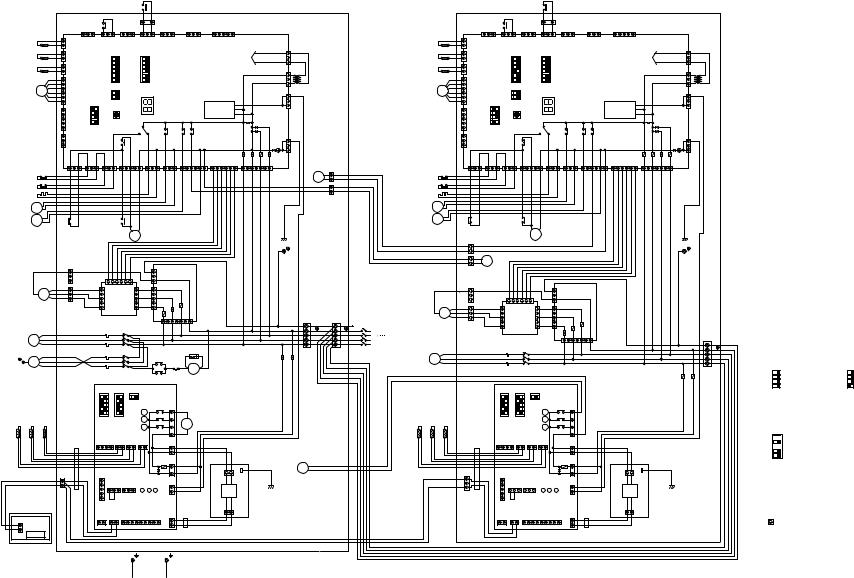
- 19 -
TH3-1
TH2-1
TH1-1
LEV1
63L1
63H11
CH1
21S41
SV11
MF21
(*1)
BLACK
WHITE
MC1 RED
BLACK
WHITE
PE MF1 RED
TH4-1 TH5-1 TH6-1
REMOTE
CONTROLLER
REMOTE CONTROLLER
BOARD
TB6 LCD
|
|
|
|
|
|
|
|
|
|
|
|
63H21 |
|
|
|
|
|
|
|
|
|
|
|
|
|
|
|
|
|
|
|
|
|
|
|
|
|
|
|
|
|
|
|
|
|
|
2 |
|
1 |
C14 |
|
|
|
|
|
|
|
|
|
|
CONTROL BOX NO.1 |
|
|||
|
|
|
|
|
X11 |
|
|
|
|
|
|
|
|
|
|
|
|
|
|
|
|
|
|
|
|
|
||||||
|
|
|
|
|
1 |
|
|
|
|
|
3 |
|
1 |
|
|
|
|
|
|
|
|
|
|
|
|
|
|
|
|
|||
|
|
|
|
|
|
3 |
|
|
|
|
|
|
|
|
|
|
|
|
|
|
|
|
|
|
|
|
|
|
||||
1 |
CN4 |
|
CN3D |
|
CN3S |
|
CN3N |
|
|
CN24 |
|
CN27 |
|
CN81 |
|
CN51 |
|
|
|
|
|
|
|
|
||||||||
2 |
|
|
|
|
|
|
|
|
|
|
|
|
|
|
|
|
|
|
|
|
|
|
|
|
|
|
|
|
|
|
|
|
1 |
CN3 |
|
|
|
|
|
|
|
|
|
|
|
|
|
|
|
|
|
|
|
|
|
|
|
DC POWER |
|
|
|
1 |
|
||
2 |
|
|
|
|
|
6 |
|
|
|
|
|
6 |
|
|
|
|
|
|
|
|
|
|
|
|
|
|
|
|
||||
|
|
|
|
|
|
|
|
|
|
|
|
|
|
|
|
|
|
|
|
|
SUPPLY |
|
|
|
|
|
||||||
|
|
|
|
|
|
|
|
|
|
|
|
|
|
|
|
|
|
|
|
|
|
|
|
|
|
|
|
|||||
1 |
|
|
|
|
|
|
5 |
|
|
|
|
|
5 |
|
|
|
|
|
|
|
|
|
|
|
|
|
|
|
|
CN34 |
3 |
|
CN2 |
|
|
|
|
|
4 |
|
|
SW1 |
|
4 |
|
|
SW2 |
|
|
|
|
|
|
|
|
|
|
|
|
|
|||||
2 |
|
|
|
|
|
3 |
|
|
|
3 |
|
|
|
|
|
|
|
|
|
|
|
|
|
|
|
1 |
|
|||||
|
|
|
|
|
|
|
2 |
|
|
|
|
|
2 |
|
|
|
|
|
|
|
|
|
|
|
|
|
|
|
|
|
|
|
|
|
|
|
|
|
|
1 |
|
|
|
|
|
1 |
|
|
|
|
|
OUTDOOR MAIN BOARD |
|
|
|
|
|
|
|
|
|||||
|
|
|
|
|
|
|
|
ON OFF |
|
|
|
ON OFF |
|
|
|
|
|
|
|
|
3 TR1 |
|
||||||||||
|
CN40 |
|
|
|
|
|
2 |
|
|
|
|
|
|
|
|
|
|
|
|
|
|
|
|
CN28 |
|
|||||||
|
|
|
|
|
|
|
|
SW4 |
|
|
|
|
|
|
|
|
|
|
|
|
|
|
|
|
|
|
|
|
|
|||
|
|
|
|
|
|
|
1 |
|
|
|
|
|
|
|
|
|
|
|
|
|
|
|
|
|
|
|
|
|
1 |
|
||
|
|
|
(*2)SW5 |
|
|
ON OFF |
|
|
|
|
|
|
|
|
|
|
|
|
|
|
|
|
|
|
|
|
|
|||||
|
|
|
|
|
|
|
|
|
|
|
|
|
|
|
|
|
|
TRANSMISSION |
|
|
|
|
|
|
3 |
|
||||||
|
|
|
|
4 |
|
|
|
|
|
|
|
LED1 |
|
|
|
|
|
|
|
|
|
|
|
|
|
|
|
CNS3 |
|
|||
|
|
|
|
3 |
|
|
|
|
|
SW3 |
|
|
|
|
|
|
|
|
|
|
CIRCUIT |
|
|
|
|
|
|
|
||||
|
CNMNT |
|
2 |
|
|
|
|
|
|
|
|
|
|
|
|
|
|
|
|
|
|
|
|
|
|
|
|
|
|
|||
|
|
1 |
|
|
|
|
|
|
|
|
|
|
|
|
|
|
|
|
|
|
|
|
|
|
|
|
|
|
|
|
||
|
|
|
|
ON OFF |
|
|
|
|
|
X03 |
|
|
|
|
X01 |
X02 |
|
|
X05 |
|
|
|
|
|
|
|
|
|
|
|||
|
|
|
|
|
|
|
|
|
|
|
|
|
|
|
|
|
|
|
|
|
|
|
|
|
|
|
|
|||||
|
|
|
|
|
|
|
|
|
|
|
|
|
|
|
|
|
|
|
|
|
|
|
|
|
|
|
CNFG |
|
|
|||
|
CNVMNT |
|
|
|
|
|
|
X04 |
|
|
|
|
|
|
|
|
|
|
|
|
|
|
|
|
|
|
|
|
|
|||
|
|
|
|
|
|
|
|
|
|
|
|
|
|
|
|
|
|
|
|
|
|
|
|
|
|
|
1 |
|
||||
|
|
|
|
|
|
|
|
|
|
|
|
|
|
|
|
|
|
|
|
|
|
|
|
|
|
|
|
|
|
|||
|
|
|
|
|
|
|
|
|
|
|
|
|
|
|
|
|
|
|
|
|
|
|
|
|
|
|
|
|
|
|
3 |
|
|
CN23 |
|
CN22 |
CN21 |
|
CN26 |
|
|
|
|
CN25 |
|
CN53 |
|
CN52 |
|
|
CNFC1 |
|
|
F01 |
F04 |
F02 |
F03 |
|
|
||||||
|
|
|
|
|
|
|
|
|
|
|
|
|
|
|
|
|
|
C18 |
||||||||||||||
|
|
|
|
|
|
|
|
|
|
|
|
|
|
|
|
|
|
|
|
|
|
|
|
|
|
|
|
|
1 CN20 |
|
||
|
1 |
3 |
1 |
|
3 |
1 |
|
3 |
|
1 |
3 |
|
5 |
|
1 |
|
3 |
1 |
3 |
1 |
3 |
5 |
6 |
1 |
6 |
7 |
5 |
3 |
X11 |
1 |
||
|
|
|
|
|
|
|
|
|
|
|
|
|
|
|
|
|
|
|
|
|
|
|
|
|
|
L1 |
N |
L2 |
L3 |
|
2 |
|
|
|
|
|
|
|
|
|
|
|
|
|
|
|
|
|
|
|
|
|
|
|
|
|
|
|
|
|
2 |
||||
|
|
|
|
|
|
|
|
|
|
|
|
|
|
|
|
|
|
|
|
|
|
|
|
|
|
|
|
|
|
|
|
|
|
|
|
|
|
|
|
|
|
|
|
|
|
|
|
|
|
|
|
|
|
|
|
|
|
|
|
|
|
|
|
|
1 |
|
|
|
|
|
|
|
|
|
|
|
|
|
|
|
|
|
|
|
|
|
|
|
|
|
|
|
|
|
|
|
|
C28 |
51C1 |
|
|
|
|
|
|
52C1 |
|
|
|
|
|
|
|
|
|
|
|
|
|
|
|
|
|
|
|
|
|
|
|
||
|
|
|
|
|
|
|
|
|
|
|
|
52C1 |
|
|
|
|
|
|
|
|
|
|
|
|
|
|
|
|
|
|
|
|
|
|
|
|
|
|
|
|
|
|
|
|
|
|
|
|
|
|
|
|
|
|
|
|
|
|
|
|
|
|
PE |
|
|
|
C12 |
|
|
|
|
|
|
|
|
|
|
|
|
|
|
|
|
CNOUT2 |
|
|
|
|
|
|
|
|
|
|
|
|
|
|
|
|
|
|
|
|
|
|
|
|
|
|
|
|
|
|
|
|
|
|
|
|
|
|
|
|
|
|
|
|
|
||
|
3 |
|
|
|
|
|
1 |
|
|
|
|
6 |
|
|
|
3 |
|
|
N.F.BOARD |
|
|
|
|
|
|
|
|
|
|
|
||
|
1 |
|
|
|
|
|
|
|
|
|
|
|
|
|
|
|
|
|
|
|
|
|
|
|
|
|
|
|
|
|
||
|
|
|
|
|
|
|
|
|
|
|
|
|
|
|
1 |
|
|
|
|
|
|
|
|
|
|
|
|
|
GREEN/YELLOW |
|
|
|
|
1 |
|
|
|
3 |
CNFAN |
CNPOW |
3 |
|
3 |
|
|
F30 |
|
|
|
|
|
|
|
|
|
|
|
|
|||||||
|
3 |
|
|
|
5 |
|
|
CNFC2 |
|
|
5 |
|
5 |
|
CNOUT1 |
|
|
|
|
|
|
|
|
|
|
|
|
|
||||
|
|
|
|
|
|
|
|
|
|
|
|
|
|
|
|
|
|
|
|
|
|
|
|
|
|
|
|
|||||
|
C11 |
|
|
|
1 |
|
|
F.C. |
|
|
1 |
|
1 |
|
F20 |
|
|
|
|
|
|
|
|
|
|
|
|
|
||||
|
|
|
|
|
|
|
BOARD |
|
|
|
F10 |
|
|
|
|
|
|
|
|
|
|
|
|
|
|
|||||||
|
|
|
|
|
|
|
|
|
|
|
|
|
|
|
|
|
|
|
|
|
|
|
|
|
|
|
|
|
|
|
||
|
|
|
|
|
|
51C1 |
|
|
52C1 |
|
|
|
|
|
|
1 |
3 5 |
|
7 |
CNIN |
|
|
|
|
|
|
|
BLUE |
PE |
PE |
||
|
|
|
|
|
|
|
|
|
|
|
|
|
|
|
|
|
|
|
|
|
|
|
|
|
|
BLACK |
N |
N |
||||
|
|
|
|
|
|
|
|
|
|
|
|
|
|
|
|
|
|
|
|
|
|
|
|
|
|
|
|
|
|
|||
|
|
|
|
|
|
|
|
|
|
|
|
|
|
|
|
|
|
|
|
|
|
|
|
|
|
|
|
|
|
WHITE |
L3 |
L3 |
|
|
|
|
|
|
|
|
|
|
|
|
|
|
|
|
|
|
|
|
|
|
|
|
|
|
|
|
|
|
RED |
L2 |
L2 |
|
|
|
|
|
|
|
|
|
|
52F |
|
|
|
|
|
|
|
|
|
|
CR |
|
|
|
|
|
|
|
|
L1 |
L1 |
|
|
|
|
|
|
RED |
51F |
|
|
|
|
|
|
|
|
|
|
|
|
|
|
|
|
|
|
|
|
TB11 |
TB1 |
||||
|
|
|
|
|
WHITE |
|
|
|
|
|
|
|
|
|
|
|
X2 |
51F |
|
|
|
|
|
|
|
|
|
|
F21 F11 |
|
RED |
|
|
|
|
|
|
BLACK |
|
|
|
|
|
|
|
|
|
|
|
X1 |
|
52F |
|
|
|
|
|
|
|
|
WHITE |
||||
|
|
|
|
|
|
|
|
|
|
|
|
|
|
|
|
|
|
|
|
|
|
|
|
|
|
|
|
|
BLACK |
|||
|
|
|
|
|
|
|
|
|
|
|
|
|
|
|
|
|
|
|
|
|
|
|
|
|
|
|
|
|
|
|
|
|
|
|
|
|
|
|
|
|
|
|
|
|
|
|
|
|
|
|
|
|
|
|
|
|
|
|
|
|
|
|
|
|
BLUE |
|
|
|
|
|
|
|
|
|
|
|
|
|
|
|
|
|
|
|
|
|
|
|
|
|
|
|
|
|
|
|
|
GREEN/YELLOW |
|
INDOOR |
|
|
ON OFF |
ON OFF |
ON OFF |
|
|
|
|
|
|
|
|
|
|
|
|
|
|
|
|
|
|
|
|||||||
CONTROLLER BOARD |
|
|
|
|
|
|
|
|
|
|
|
|
|
|
|
|
|
|
|
|||||||||||||
5 |
|
|
5 |
|
|
|
|
|
|
|
|
|
|
|
|
|
|
|
|
|
|
|
|
|
|
|
|
|||||
|
|
|
|
|
|
|
|
|
|
|
|
|
|
|
|
|
|
|
|
|
|
|
|
|
|
|
|
|
|
|
||
|
|
|
|
|
4 |
|
|
4 |
|
|
|
SWE |
|
|
|
|
|
|
|
|
|
|
|
|
|
|
|
|
|
|
|
|
|
|
|
|
|
3 |
|
|
3 |
|
|
|
|
|
|
|
|
|
|
|
|
|
|
|
|
|
|
|
|
|
|
||
|
|
|
|
|
2 |
|
|
2 |
|
|
|
|
|
|
X6 |
X6 |
|
1 |
|
|
|
|
|
|
|
|
|
|
|
|
|
|
|
|
|
|
|
1 |
|
|
1 |
|
|
|
|
|
|
X5 |
|
3 |
|
|
|
|
|
|
|
|
|
|
|
|
|
||
|
|
|
|
|
|
SW1 |
(*3) |
SW2 |
|
|
|
|
X5 |
|
|
|
|
|
|
|
|
|
|
|
|
|
|
|||||
|
|
|
|
|
|
|
|
|
|
X4 |
|
5 |
|
X1 |
|
|
|
|
|
|
|
|
|
|
|
|||||||
|
|
|
|
|
|
|
|
|
|
|
|
|
|
|
X4 |
|
|
|
|
|
|
|
|
|
|
|
|
|
||||
|
|
|
|
|
|
|
|
|
|
|
|
|
|
|
|
|
|
7 |
|
|
|
|
|
|
|
|
|
|
|
|
|
|
|
|
|
|
|
|
|
|
|
|
|
|
|
|
|
|
|
|
|
|
|
|
|
|
|
|
|
|
|
|
|
|
|
|
|
|
|
|
|
CN41 |
CN29 |
CN21 |
CN20 |
|
|
|
FAN |
|
|
|
|
|
|
|
|
|
|
|
|
|
||||||
|
FB21 |
|
|
1 |
2 |
3 |
4 |
1 |
2 |
1 |
2 |
1 |
2 |
|
|
|
|
|
|
|
|
|
|
|
|
|
|
|
|
|||
|
|
|
|
|
|
1 |
|
|
|
|
|
|
|
|
|
|
|
|
|
|||||||||||||
|
|
|
|
|
|
|
|
|
|
|
|
|
|
|
|
|
|
|
|
|
|
|
|
|
|
|
|
|
|
|||
|
|
|
|
|
|
|
|
|
|
|
|
|
|
|
|
|
|
|
3 |
|
|
|
|
|
|
|
|
|
|
|
|
|
|
|
|
|
|
|
|
|
|
|
|
|
|
|
|
|
|
FUSE |
CNDK |
|
|
|
|
|
|
|
|
|
|
|
|
|
|
|
|
|
|
|
|
|
|
|
|
|
|
|
|
|
|
ZNR |
|
1 |
|
|
|
|
1 |
3 |
|
|
|
|
|
X2 |
|
|
|
|
|
|
|
|
|
|
|
|
|
|
|
|
|
|
|
3 |
|
|
|
|
|
|
|
|
|
|
|||||
TB5 |
|
|
|
|
|
|
|
|
|
|
|
|
|
|
|
|
|
|
|
CNSK |
|
TAB1 |
|
|
|
|
|
|
||||
|
|
|
|
|
|
|
|
|
|
|
|
|
|
|
|
|
|
|
|
|
|
|
|
|
|
|
|
|
||||
1 |
|
|
|
|
1 |
|
CN31 |
CN32 |
|
|
|
|
|
|
CND |
|
|
|
|
|
|
|
|
|
|
|
|
|||||
|
|
|
|
|
|
|
|
|
|
|
|
|
|
|
|
|
|
|
|
|
|
|
|
|||||||||
2 |
|
|
|
|
2 |
|
1 |
2 |
3 |
1 |
2 |
3 |
LED1 |
LED2 |
LED3 |
1 |
|
|
|
|
DC |
|
|
|
|
|
|
|
||||
|
|
|
|
3 |
|
|
|
|
|
|
|
|
|
|
|
|
|
|
|
|
|
|
|
|
|
|
|
|
||||
|
|
|
|
|
4 |
|
|
|
|
|
|
|
|
|
|
|
|
|
3 |
|
|
|
|
13.1V |
|
|
|
|
|
|
|
|
|
|
|
|
|
5 |
|
|
|
|
|
|
|
|
|
|
|
|
|
CN3C |
|
|
|
|
|
|
|
|
|
|
|
|
|
|
|
|
|
|
CN51 |
|
|
|
|
|
|
|
|
|
|
|
CN2D |
|
|
|
|
1 |
2 |
|
INDOOR |
|
|
|
||||
|
|
|
|
|
|
|
|
|
|
|
|
|
|
|
|
|
|
|
|
|
|
|
|
|
|
|||||||
|
|
|
|
|
CN2L |
CN22 |
1 |
2 |
3 |
CN90 |
7 |
8 |
DC13.1V |
FB11 |
|
|
CN2S |
|
|
POWER BOARD |
|
|
||||||||||
|
|
|
|
|
1 |
2 |
|
1 |
2 |
4 |
5 |
6 |
9 |
1 |
|
|
|
|
|
|
|
|
|
|
|
|
|
|||||
|
|
|
|
|
|
|
|
|
|
|
|
|
|
|
|
|
|
|
2 |
|
|
|
|
|
|
|
|
|
|
|
|
|
CIRCUIT BREAKER (FIELD SUPPLY) PRH-P400MYA: 63A PRH-P500MYA: 70A
 PE
PE
POWER SUPPLY
380/400/415V
50HZ
|
|
|
|
63H22 |
|
|
|
|
|
|
|
|
2 |
1 |
C14 |
|
CONTROL BOX NO.2 |
|
|
X22 |
|
|
|
|
||
|
|
1 |
3 |
1 |
|
|
|
|
|
|
3 |
|
|
|
|||
1 |
CN4 |
CN3D |
CN3S |
CN3N |
CN24 |
CN27 |
CN81 |
CN51 |
2 |
|
|
|
|
|
|
|
TH3-2 |
1 |
|
|
|
|
|
|
|
|
TH2-2 |
2 |
CN3 |
|
6 |
|
6 |
|
|
|
1 |
|
|
5 |
|
5 |
|
|
|
|
|
CN2 |
|
4 |
SW1 |
4 |
SW2 |
|
|
|
|
2 |
|
|
|
|||||
TH1-2 |
|
3 |
3 |
|
|
||||
|
|
|
2 |
|
2 |
|
|
|
|
|
|
|
|
1 |
|
1 |
|
OUTDOOR MAIN BOARD |
|
|
|
|
|
|
ON OFF |
|
ON OFF |
||
LEV2 |
|
CN40 |
|
|
|
|
|
||
|
|
2 |
SW4 |
|
|
|
|
||
|
|
|
|
1 |
|
|
|
|
|
|
|
|
|
|
|
|
|
|
|
|
|
|
(*2)SW5 |
|
ON OFF |
|
|
|
TRANSMISSION |
|
|
|
4 |
|
|
LED1 |
|
|
|
|
|
|
3 |
|
SW3 |
|
|
CIRCUIT |
|
|
|
CNMNT |
2 |
|
|
|
|
|
|
|
|
1 |
|
|
|
|
|
|
|
|
|
|
ON OFF |
|
|
X03 |
X01 |
X02 |
X05 |
|
|
|
|
|
|
||||
|
|
|
|
|
|
|
|||
CNVMNT |
X04 |
|
|
CN23 |
CN22 |
|
CN21 |
|
CN26 |
|
|
|
CN25 |
|
CN53 |
|
CN52 |
|
|
|||||
63L2 |
|
1 |
3 |
1 |
3 |
1 |
|
3 |
|
1 |
3 |
|
5 |
1 |
|
3 |
1 |
3 |
1 |
3 |
5 |
6 |
|
|
|
|
|
|
|
|
|
|
|
|
|
|
|
|
|
|
|
|
|
|
|
63H12 |
|
|
|
|
|
|
|
|
|
|
|
|
|
|
|
|
|
|
|
|
|
|
CH2 |
|
|
|
|
|
|
|
|
|
|
|
|
|
|
|
|
|
|
|
|
|
|
21S42 |
|
|
|
|
|
|
|
|
|
|
|
|
|
|
|
|
|
|
|
|
|
|
SV12 |
|
51C2 |
|
|
|
|
|
52C2 |
|
|
|
|
|
|
|
|
|
|
|
|
|
|
|
|
C28 |
|
|
|
|
|
|
|
|
|
52C2 |
|
|
|
|
|
|
|
|
|
|
|
|
1 |
|
|
|
|
|
|
|
|
|
|
|
|
|
|
|
|
|
|
|
|
|
|
|
|
|
|
|
|
|
|
|
|
|
|
|
|
|
|
|
|
|
|
|
|
|
|
2 |
|
|
|
|
|
|
|
|
|
|
|
|
|
|
|
|
|
|
|
|
|
|
2 |
X22 |
|
|
|
|
|
|
|
|
|
|
|
|
|
|
|
|
|
|
|
|
|
1 |
|
|
|
|
|
|
|
|
|
|
|
|
|
|
|
|
|
|
|
|
|
C18 |
|
|
|
|
|
|
|
|
|
|
|
|
|
|
|
|
|
|
|
|
|
|
C12 |
|
|
|
|
|
|
|
|
|
|
|
|
|
CNOUT2 |
|
|
|
|
||
|
|
|
|
|
|
|
|
|
|
|
|
|
|
|
|
|
|
|
|
|||
|
|
3 |
|
|
|
|
1 |
|
|
|
|
6 |
|
|
3 |
|
|
N.F.BOARD |
|
|
||
|
|
1 |
|
|
|
|
|
|
|
|
|
|
|
|
|
|
|
|
|
|
||
|
|
|
|
|
|
|
|
|
|
|
|
|
|
1 |
CNOUT1 |
|
|
|
|
|||
|
|
3 |
|
|
5 |
|
|
CNFC2 |
|
|
5 |
|
5 |
|
|
|
|
|||||
|
MF22 |
|
|
|
CNFAN |
|
CNPOW |
|
|
|
|
|
|
|
|
|||||||
(*1) |
|
|
|
|
|
|
|
|
|
|
|
F30 |
|
|
|
|||||||
|
1 |
|
|
3 |
|
|
3 |
|
3 |
|
|
|
|
|
||||||||
|
|
|
|
|
|
|
|
|
|
|
|
|
|
|
|
|||||||
|
|
C11 |
|
|
1 |
|
|
F.C. |
|
|
1 |
|
1 |
|
F20 |
|
|
|
|
|||
|
|
|
|
|
|
|
BOARD |
|
|
|
F10 |
|
|
|
|
|
|
|||||
|
|
|
|
|
|
|
|
|
|
|
|
|
|
|
|
|
|
|
|
|
|
|
|
|
|
|
|
|
51C2 |
|
|
52C2 |
|
|
|
|
1 |
|
3 |
5 |
7 |
CNIN |
|
||
|
BLACK |
|
|
|
|
|
|
|
|
|
|
|
|
|
|
|
|
|
||||
MC2 |
WHITE |
|
|
|
|
|
|
|
|
|
|
|
|
|
|
|
|
|
|
|
|
|
RED |
|
|
|
|
|
|
|
|
|
|
|
|
|
|
|
|
|
|
|
|
|
|
|
|
|
|
|
|
|
|
|
|
|
|
|
|
|
|
|
|
|
|
|
|
|
|
|
INDOOR |
|
ON OFF |
ON OFF |
ON OFF |
|
|
|
|
|
|
|
|
|
|||||||
|
|
CONTROLLER BOARD |
|
|
|
|
|
|
|
|
|
|||||||||||
|
|
5 |
|
|
5 |
|
|
|
|
|
|
|
|
|
|
|
|
|
|
|||
|
|
|
|
|
|
|
|
|
|
|
|
|
|
|
|
|
|
|
|
|
||
|
|
|
|
|
4 |
|
|
4 |
|
|
|
SWE |
|
|
|
|
|
|
|
|
|
|
|
|
|
|
|
3 |
|
|
3 |
|
|
|
|
|
|
|
|
|
|
|
|
||
|
|
|
|
|
2 |
|
|
2 |
|
|
|
|
|
X6 |
X6 |
|
1 |
|
|
|
|
|
|
|
|
|
|
1 |
|
|
1 |
|
|
|
|
|
X5 |
|
3 |
|
|
|
|
||
TH4-2 TH5-2 |
TH6-2 |
|
|
|
|
SW1 |
(*3) |
|
SW2 |
|
|
|
X5 |
|
|
|
|
|
||||
|
|
|
|
|
|
|
|
X4 |
|
5 |
|
|
|
|
||||||||
|
|
|
|
|
|
|
|
|
|
|
|
X4 |
|
|
|
|
|
|||||
|
|
|
|
|
|
|
|
|
|
|
|
|
|
|
|
|
7 |
|
|
|
|
|
|
|
|
|
|
|
|
|
|
|
|
|
|
|
|
|
|
|
|
|
|
|
|
|
|
|
|
|
|
CN41 |
CN29 |
CN21 |
CN20 |
|
|
|
FAN |
|
|
|
|
|||||
|
|
FB22 |
|
1 |
2 |
3 |
4 |
1 |
2 |
1 |
2 |
1 |
2 |
|
|
|
|
|
|
|
||
|
|
|
|
|
|
1 |
|
|
|
|
||||||||||||
|
|
|
|
|
|
|
|
|
|
|
|
|
|
|
|
|
|
|
|
|||
|
|
|
|
|
|
|
|
|
|
|
|
|
|
|
|
|
|
3 |
|
|
|
|
|
|
|
|
|
|
|
|
|
|
|
|
|
|
|
|
FUSE |
|
CNDK |
|
|
|
|
|
|
|
|
|
|
|
|
|
|
|
|
|
|
|
ZNR |
|
1 |
|
|
|
|
|
|
|
C19 |
|
|
|
|
|
|
|
|
|
|
|
|
|
3 |
|
|
|
|
||
|
|
1 |
|
|
1 |
|
CN31 |
CN32 |
|
|
|
|
|
CND |
|
|
|
|
||||
|
|
|
|
|
|
|
|
|
|
|
|
|
|
|
||||||||
|
|
3 |
|
|
2 |
|
1 |
2 |
3 |
1 |
2 |
3 |
LED1 |
LED2 |
LED3 |
|
1 |
|
|
|
|
|
|
|
|
|
|
3 |
|
|
|
|
|
|
|
|
|
|
|
|
|
|
|
|
|
43
5CN3C
CN51
CN2L |
CN22 |
|
|
|
CN90 |
|
|
|
|
CN2D |
FB12 |
|||
1 |
2 |
3 |
6 |
7 |
8 |
9 |
DC13.1V |
|||||||
1 |
2 |
1 |
2 |
4 |
5 |
1 |
|
|||||||
|
|
|
|
|
|
|
|
|
|
|
|
|
2 |
|
CNFC1
1
1 3
CNSK
DC 13.1V
1 2
CN2S
DC POWER |
|
|
|
1 |
||
|
|
|
|
|||
SUPPLY |
|
|
|
3 |
||
|
|
|
|
|
CN34 |
|
|
|
|
|
|
|
1 |
|
|
|
|
|
CN28 |
3 TR2 |
|
|
|
|
|
|
1 |
|
|
|
|
|
CNS3 |
3 |
|
|
|
|
|
|
|
|
|
|
|
|
CNFG |
|
|
|
|
|
|
|
1 |
|
|
|
|
|
|
3 |
|
|
F01 |
F04 |
F02 |
F03 |
|
6 |
7 |
5 |
3 |
1 |
CN20 |
|
|
L1 |
N |
L2 |
L3 |
|
|
|
PE |
GREEN/YELLOW |
|
BLUE |
PE |
BLACK |
N |
WHITE |
L3 |
RED |
L2 |
|
L1 |
|
TB21 |
F22 |
F12 |
TAB1
INDOOR
POWER BOARD
PE |
PE |
RETURN AIR |
SUPPLY AIR |
DUCT |
DUCT |
SYMBOL |
|
NAME |
|
|
F11,F12,F21,F22 |
FUSE (15A 250VAC CLASS T) |
|
||
51C1,51C2 |
|
OVER CURRENT RELAY (COMPRESSOR) |
||
52C1,52C2 |
|
MAGNETIC CONTACTOR (COMPRESSOR) |
||
63L1,63L2 |
|
PRESSURE SWITCH (LOW PRESSURE) |
||
63H11,63H12 |
|
PRESSURE SWITCH (HIGH PRESSURE) |
||
63H21,63H22 |
|
PRESSURE SWITCH (FOR CONTROL) |
||
MC1,MC2 |
|
COMPRESSOR MOTOR |
|
|
MF21,MF22 |
|
FAN MOTOR (OUTDOOR) |
|
|
TR1,TR2 |
|
TRANSFORMER |
|
|
21S41,21S42 |
|
4-WAY VALVE |
|
|
SV11,SV12 |
|
SOLENOID VALVE |
|
|
CH1,CH2 |
|
CRANK CASE HEATER (COMPRESSOR) |
||
LEV1,LEV2 |
|
ELECTRONIC EXPANSION VALVE |
|
|
TB1,TB5,TB11,TB21 |
TERMINAL BLOCK |
|
||
MF1 |
|
FAN MOTOR (INDOOR) |
|
|
51F |
|
OVER CURRENT RELAY (INDOOR FAN MOTOR) |
||
52F |
|
MAGNETIC CONTACTOR (INDOOR FAN MOTOR) |
||
TH1-1,TH1-2 |
|
|
LIQUID PIPE TEMP |
|
TH2-1,TH2-2 |
|
|
DISCHARGE TEMP |
OUTDOOR |
TH3-1,TH3-2 |
|
THERMISTOR |
COND/EVA TEMP |
|
TH4-1,TH4-2 |
|
ROOM TEMP |
|
|
|
|
|
||
TH5-1,TH5-2 |
|
|
LIQUID PIPE TEMP |
INDOOR |
TH6-1,TH6-2 |
|
|
COND/EVA TEMP |
|
CR |
|
SURGE KILLER |
|
|
FB11,FB12,FB21,FB22 |
FERRITE CORE |
|
||
X1,X2,X11,X22 |
AUXILIARY RELAY |
|
||
INDOOR |
X4-6 |
AUXILIARY RELAY |
|
|
CONTROLLER |
SW1 |
SWITCH (MODEL SELECTION) |
|
|
BOARD |
SW2 |
SWITCH (CAPACITY CORD) |
|
|
|
SWE |
SWITCH (EMERGENCY OPERATION) |
||
|
LED1 |
LED (POWER SUPPLY) |
|
|
|
LED2 |
LED (POWER SUPPLY<REMOTE CONTROLLER>) |
||
|
LED3 |
LED (TRANSMISSION<INDOOR.OUTDOOR>) |
||
|
ZNR |
VARISTOR |
|
|
|
FUSE |
FUSE (T6.3AL250V) |
|
|
OUTDOOR |
F01-F04 |
FUSE (6.3A 250VAC CLASS F) |
|
|
MAIN BOARD |
LED1 |
LED (FOR SERVICE) |
|
|
|
X01-X05 |
AUXILIARY RELAY |
|
|
|
SW1-5 |
SWITCH |
|
|
N.F.BOARD |
F10-F30 |
FUSE (6.3A 250VAC CLASS F) |
|
|
REMOTE CONTROLLER |
|
|
|
|
SYMBOL |
|
NAME |
|
|
TB6 |
|
TERMINAL BLOCK |
|
|
Note: 1. The dotted lines show field wiring.
2.Color of earth wire is yellow and green twisting.
3.Specification subject to change without notice.
4.This motor(*1) includes auto reset type internal thermostat.
5.SW5(*2)[OUTDOOR MAIN BOARD] shows PRHP500MYA setting.
In case of PRH-P400MYA setting is shown as below.
Control box no.1 |
Control box no.2 |
||||
(*2)SW5 |
(*2)SW5 |
||||
4 |
|
[OUTDOOR MAIN |
4 |
|
[OUTDOOR MAIN |
3 |
|
3 |
|
||
2 |
|
BOARD] |
2 |
|
BOARD] |
1 |
|
1 |
|
||
|
|
|
|
||
|
ON OFF |
|
ON OFF |
||
6.SW2(*3)[INDOOR CONTROLLER BOARD] shows PRH-P500MYA setting.
In case of PRH-P400MYA setting is shown as below.
ON OFF
5 
4
3  [INDOOR CONTROLLER BOARD]
2
1
(*3)SW2
7.Emergency operation
If a trouble occurs with either the remote controller or the unit microcomputer and no other trouble exists, emergency operation for cooling or heating can be performed by changing the setting of switch (SWE) "ON" on the indoor controller board.
8.mark is connector.
Caution,
1.To protect compressor and fan motor (indoor) from abnormal current, over current relays is installed. Therefore, do not change factory set value of over current relays.
P400MYA/P500MYA-PRH Models •

[2] Skeleton of Transmission Line Connection
(1) |
System |
|
|
|
Unit |
|
|
|
|
|
|
|
|||||
|
|
|
|
|
|
|
|
|
|
|
|
|
|
|
|||
|
|
|
|
|
|
|
|
|
|
|
|
|
|
|
|
|
|
|
|
|
|
|
|
|
Transmission line |
|
|
|
|
|
|
|
|||
|
|
|
|
|
|
|
|
|
|
|
|
|
|
|
|
||
|
|
|
|
|
|
|
|
|
|
|
|
|
|
|
|||
|
|
|
|
|
|
Remote |
|
|
|
|
|
|
|
|
|||
|
|
|
|
|
controller |
|
|
|
|
|
|
|
|||||
0 Technical Data to Meet LVD |
|
|
|
|
|
|
|
||||||||||
[1] |
|
Standard Operation Data |
|
|
|
|
|
|
|
||||||||
(1) PRH-P8MYA/P200MYA |
|
|
|
|
|
|
|
||||||||||
|
|
|
|
|
|
|
|
|
|
|
|
|
|
|
|
|
|
|
|
|
Operating condition |
|
|
Cooling |
|
|
Heating |
|
|||||||
|
|
|
|
|
|
|
|
|
|
|
|
|
|
|
|
|
|
condition |
|
Voltage |
|
|
|
|
|
|
|
|
V |
380 |
400 |
415 |
380 |
400 |
415 |
|
|
|
|
|
|
|
|
|
|
||||||||
|
|
|
|
|
|
|
|
|
|
|
|
|
|
|
|
|
|
|
|
Power source frequency |
|
Hz |
50 |
50 |
50 |
50 |
50 |
50 |
|||||||
|
|
|
|
|
|
|
|
|
|
|
|
|
|
|
|
|
|
Operating |
|
Indoor air condition (DB/WB) |
|
°C |
27/19 |
27/19 |
27/19 |
20/– |
20/– |
20/– |
|||||||
|
|
|
|
|
|
|
|
|
|
|
|
|
|
|
|
||
|
Refrigerant charge |
|
kg |
7.7 |
7.7 |
7.7 |
7.7 |
7.7 |
7.7 |
||||||||
|
|
Outdoor air condition (DB/WB) |
|
°C |
35/– |
35/– |
35/– |
7/6 |
7/6 |
7/6 |
|||||||
|
|
|
|
|
|
|
|
|
|
|
|
|
|
|
|
|
|
characteristics |
|
Total |
|
Rated current |
|
A |
14.7 |
14.7 |
14.7 |
14.5 |
14.5 |
14.5 |
|||||
|
|
|
|
||||||||||||||
|
|
|
|
|
|
|
|
|
|
|
|
|
|
|
|
|
|
|
|
Compressor current |
|
A |
11.9 |
11.9 |
11.9 |
11.7 |
11.7 |
11.7 |
|||||||
|
|
|
|
|
|
|
|
|
|
|
|
|
|
|
|
|
|
Electrical |
|
O/D FAN |
|
Rated current |
|
A |
1.1 |
1.1 |
1.1 |
1.1 |
1.1 |
1.1 |
|||||
|
|
|
|
|
|
|
|
|
|
|
|
|
|
|
|
|
|
|
I/D FAN |
|
Rated current |
|
A |
1.7 |
1.7 |
1.7 |
1.7 |
1.7 |
1.7 |
||||||
|
|
|
|
|
|
|
|
|
|
|
|
|
|
|
|
|
|
|
|
Discharge pressure |
|
MPa |
2.25 |
2.25 |
2.25 |
1.72 |
1.72 |
1.72 |
|||||||
circuit |
|
|
|
|
|
|
|
|
|
|
|
|
|
|
|
|
|
|
Suction pressure |
|
MPa |
0.56 |
0.56 |
0.56 |
0.38 |
0.38 |
0.38 |
||||||||
|
|
|
|||||||||||||||
|
|
|
|
|
|
|
|
|
|
|
|
|
|
|
|
|
|
Refrigerant |
|
Discharge refrigerant temperature |
|
°C |
77 |
77 |
77 |
66 |
66 |
66 |
|||||||
|
|
|
|
|
|
|
|
|
|
|
|
|
|
|
|
|
|
|
Suction refrigerant temperature |
|
°C |
10 |
10 |
10 |
-1 |
-1 |
-1 |
||||||||
|
|
|
|||||||||||||||
|
|
|
|
|
|
|
|
|
|
|
|
|
|
|
|
|
|
|
|
Liquid pipe temperature (at piping sensor) |
|
°C |
48 |
48 |
48 |
0 |
0 |
0 |
|||||||
|
|
|
|
|
|
|
|
|
|
|
|
|
|
|
|
|
|
|
|
Compressor shell bottom temperature |
|
°C |
33 |
33 |
33 |
28 |
28 |
28 |
|||||||
|
|
|
|
|
|
|
|
|
|
|
|
|
|
|
|
|
|
(2) PRH-P10MYA/P250MYA
|
|
Operating condition |
|
|
Cooling |
|
|
Heating |
|
||
|
|
|
|
|
|
|
|
|
|
|
|
condition |
Voltage |
|
|
V |
380 |
400 |
415 |
380 |
400 |
415 |
|
|
|
|
|||||||||
|
|
|
|
|
|
|
|
|
|
||
|
Power source frequency |
Hz |
50 |
50 |
50 |
50 |
50 |
50 |
|||
|
|
|
|
|
|
|
|
|
|
||
Operating |
Indoor air condition (DB/WB) |
°C |
27/19 |
27/19 |
27/19 |
20/– |
20/– |
20/– |
|||
|
|
|
|
|
|
|
|
|
|||
Refrigerant charge |
kg |
8.2 |
8.2 |
8.2 |
8.2 |
8.2 |
8.2 |
||||
|
Outdoor air condition (DB/WB) |
°C |
35/– |
35/– |
35/– |
7/6 |
7/6 |
7/6 |
|||
|
|
|
|
|
|
|
|
|
|
|
|
characteristics |
Total |
|
Rated current |
A |
18.8 |
18.8 |
18.8 |
18.2 |
18.2 |
18.2 |
|
|
|
||||||||||
|
|
|
|
|
|
|
|
|
|
||
|
Compressor current |
A |
14.9 |
14.9 |
14.9 |
14.3 |
14.3 |
14.3 |
|||
|
|
|
|
|
|
|
|
|
|
|
|
Electrical |
O/D FAN |
|
Rated current |
A |
1.1 |
1.1 |
1.1 |
1.1 |
1.1 |
1.1 |
|
|
|
|
|
|
|
|
|
|
|
||
I/D FAN |
|
Rated current |
A |
2.8 |
2.8 |
2.8 |
2.8 |
2.8 |
2.8 |
||
|
Discharge pressure |
MPa |
2.31 |
2.31 |
2.31 |
1.83 |
1.83 |
1.83 |
|||
circuit |
|
|
|
|
|
|
|
|
|
|
|
Suction pressure |
MPa |
0.55 |
0.55 |
0.55 |
0.37 |
0.37 |
0.37 |
||||
|
|||||||||||
|
|
|
|
|
|
|
|
|
|
||
Refrigerant |
Discharge refrigerant temperature |
°C |
78 |
78 |
78 |
70 |
70 |
70 |
|||
|
|
|
|
|
|
|
|
|
|
||
Suction refrigerant temperature |
°C |
9 |
9 |
9 |
–1 |
–1 |
–1 |
||||
|
|||||||||||
|
|
|
|
|
|
|
|
|
|
||
|
Liquid pipe temperature (at piping sensor) |
°C |
48 |
48 |
48 |
3 |
3 |
3 |
|||
|
|
|
|
|
|
|
|
|
|
||
|
Compressor shell bottom temperature |
°C |
32 |
32 |
32 |
25 |
25 |
25 |
|||
|
|
|
|
|
|
|
|
|
|
|
|
- 20 -
(3) PRH-P16MYA/P400MYA
|
|
Operating condition |
|
|
Cooling |
|
|
Heating |
|
||
|
|
|
|
|
|
|
|
|
|
|
|
condition |
Voltage |
|
|
V |
380 |
400 |
415 |
380 |
400 |
415 |
|
|
|
|
|||||||||
|
|
|
|
|
|
|
|
|
|
||
|
Power source frequency |
Hz |
50 |
50 |
50 |
50 |
50 |
50 |
|||
|
|
|
|
|
|
|
|
|
|
||
Operating |
Indoor air condition (DB/WB) |
°C |
27/19 |
27/19 |
27/19 |
20/– |
20/– |
20/– |
|||
|
|
|
|
|
|
|
|
|
|||
Refrigerant charge 1 |
kg |
7.7 |
7.7 |
7.7 |
7.7 |
7.7 |
7.7 |
||||
|
Outdoor air condition (DB/WB) |
°C |
35/– |
35/– |
35/– |
7/6 |
7/6 |
7/6 |
|||
|
|
|
|
|
|
|
|
|
|
|
|
characteristics |
Total |
|
Rated current |
A |
29.6 |
29.6 |
29.6 |
29.2 |
29.2 |
29.2 |
|
|
|
||||||||||
|
|
|
|
|
|
|
|
|
|
||
|
Compressor current |
A |
23.8 |
23.8 |
23.8 |
23.4 |
23.4 |
23.4 |
|||
|
|
|
|
|
|
|
|
|
|
|
|
Electrical |
O/D FAN |
|
Rated current |
A |
2.2 |
2.2 |
2.2 |
2.2 |
2.2 |
2.2 |
|
|
|
|
|
|
|
|
|
|
|
||
I/D FAN |
|
Rated current |
A |
3.6 |
3.6 |
3.6 |
3.6 |
3.6 |
3.6 |
||
|
|
|
|
|
|
|
|
|
|
||
|
Discharge pressure |
MPa |
2.27 |
2.27 |
2.27 |
1.80 |
1.80 |
1.80 |
|||
circuit |
|
|
|
|
|
|
|
|
|
|
|
Suction pressure |
MPa |
0.52 |
0.52 |
0.52 |
0.40 |
0.40 |
0.40 |
||||
|
|||||||||||
|
|
|
|
|
|
|
|
|
|
||
Refrigerant |
Discharge refrigerant temperature |
°C |
79 |
79 |
79 |
68 |
68 |
68 |
|||
|
|
|
|
|
|
|
|
|
|
||
Suction refrigerant temperature |
°C |
7 |
7 |
7 |
0 |
0 |
0 |
||||
|
|||||||||||
|
|
|
|
|
|
|
|
|
|
||
|
Liquid pipe temperature (at piping sensor) |
°C |
49 |
49 |
49 |
2 |
2 |
2 |
|||
|
|
|
|
|
|
|
|
|
|
||
|
Compressor shell bottom temperature |
°C |
31 |
31 |
31 |
25 |
25 |
25 |
|||
|
|
|
|
|
|
|
|
|
|
|
|
1: For each refrigerant circuit
(4) PRH-P20MYA/P500MYA
|
|
Operating condition |
|
|
Cooling |
|
|
Heating |
|
||
|
|
|
|
|
|
|
|
|
|
|
|
condition |
Voltage |
|
|
V |
380 |
400 |
415 |
380 |
400 |
415 |
|
|
|
|
|||||||||
|
|
|
|
|
|
|
|
|
|
||
|
Power source frequency |
Hz |
50 |
50 |
50 |
50 |
50 |
50 |
|||
|
|
|
|
|
|
|
|
|
|
||
Operating |
Indoor air condition (DB/WB) |
°C |
27/19 |
27/19 |
27/19 |
20/– |
20/– |
20/– |
|||
|
|
|
|
|
|
|
|
|
|||
Refrigerant charge 1 |
kg |
8.2 |
8.2 |
8.2 |
8.2 |
8.2 |
8.2 |
||||
|
Outdoor air condition (DB/WB) |
°C |
35/– |
35/– |
35/– |
7/6 |
7/6 |
7/6 |
|||
|
|
|
|
|
|
|
|
|
|
|
|
characteristics |
Total |
|
Rated current |
A |
36.6 |
36.6 |
36.6 |
35.4 |
35.4 |
35.4 |
|
|
|
||||||||||
|
|
|
|
|
|
|
|
|
|
||
|
Compressor current |
A |
29.8 |
29.8 |
29.8 |
28.6 |
28.6 |
28.6 |
|||
|
|
|
|
|
|
|
|
|
|
|
|
Electrical |
O/D FAN |
|
Rated current |
A |
2.2 |
2.2 |
2.2 |
2.2 |
2.2 |
2.2 |
|
|
|
|
|
|
|
|
|
|
|
||
I/D FAN |
|
Rated current |
A |
4.6 |
4.6 |
4.6 |
4.6 |
4.6 |
4.6 |
||
|
Discharge pressure |
MPa |
2.28 |
2.28 |
2.28 |
1.80 |
1.80 |
1.80 |
|||
circuit |
|
|
|
|
|
|
|
|
|
|
|
Suction pressure |
MPa |
0.52 |
0.52 |
0.52 |
0.40 |
0.40 |
0.40 |
||||
|
|||||||||||
|
|
|
|
|
|
|
|
|
|
||
Refrigerant |
Discharge refrigerant temperature |
°C |
79 |
79 |
79 |
68 |
68 |
68 |
|||
|
|
|
|
|
|
|
|
|
|
||
Suction refrigerant temperature |
°C |
7 |
7 |
7 |
0 |
0 |
0 |
||||
|
|||||||||||
|
|
|
|
|
|
|
|
|
|
||
|
Liquid pipe temperature (at piping sensor) |
°C |
49 |
49 |
49 |
2 |
2 |
2 |
|||
|
|
|
|
|
|
|
|
|
|
||
|
Compressor shell bottom temperature |
°C |
31 |
31 |
31 |
25 |
25 |
25 |
|||
|
|
|
|
|
|
|
|
|
|
|
|
1: For each refrigerant circuit
- 21 -
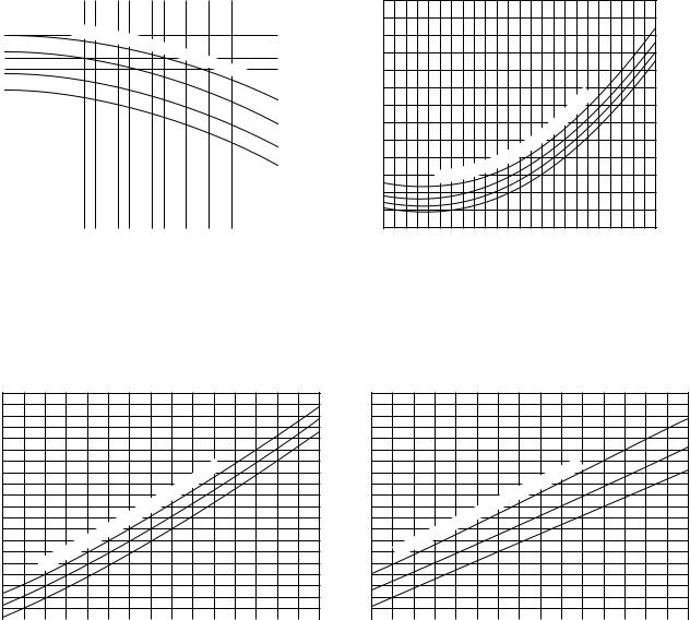
[2] Cooling Capacity Curves
|
1.4 |
|
|
|
|
|
|
|
|
|
|
|
|
|
|
|
|
|
|
|
|
|
|
|
|
|
|
|
|
|
|
|
|
|
|
|
|
|
|
|
|
|
|
|
|
|
|
|
|
|
|
|
|
|
|
|
|
|
|
|
|
|
|
|
|
|
|
|
|
|
|
|
|
|
|
|
|
|
|
|
|
|
|
|
|
|
|
|
|
|
|
|
|
|
|
Indoor |
inlet |
air |
wet |
|
|
|
|
|
|
|
|
|
|
|
|
|
|
|
|
|
|
|
|
|
|
|
|
|
|
|
|
|
|||
|
1.2 |
|
|
|
|
|
|
|
|
|
|
bulb |
|
temp |
. |
|
|
|
|
|
|
|
|
|
|
|
|
|
|
|
|
|
|
|
|
|
|
|
|
|
|||
|
|
|
|
|
|
|
|
|
|
|
|
|
|
|
<˚ |
CWB> |
|
|
|
|
|
ratio |
|
|
|
|
|
|
|
|
|
|
|
|
|
|
|
|
|
|
|
22 |
|
|
|
|
|
|
|
|
|
|
|
|
|
|
|
|
|
|
|
|
|
||
|
|
|
|
|
|
|
|
|
|
|
|
|
|
|
|
|
|
|
|
||
|
|
|
|
|
|
|
|
|
|
|
|
|
|
|
|
|
|
|
|
||
Capacity |
1 |
|
|
|
|
|
|
|
|
|
|
|
|
|
|
|
|
|
|
|
20 |
|
|
|
|
|
|
|
|
|
|
|
|
|
|
|
|
|
|
|
|
||
|
|
|
|
|
|
|
|
|
|
|
|
|
|
|
|
|
|
|
|
|
|
|
|
|
|
|
|
|
|
|
|
|
|
|
|
|
|
|
|
|
|
|
|
|
|
|
|
|
|
|
|
|
|
|
|
|
|
|
|
|
|
|
|
|
18 |
|
|
|
|
|
|
|
|
|
|
|
|
|
|
|
|
|
|
|
|
|
|
|
|
|
|
|
|
|
|
|
|
|
|
|
|
|
|
|
|
|
|
|
|
|
0.8 |
|
|
|
|
|
|
|
|
|
|
|
|
|
|
|
|
|
|
|
16 |
|
|
|
|
|
|
|
|
|
|
|
|
|
|
|
|
|
|
|
|
||
|
|
|
|
|
|
|
|
|
|
|
|
|
|
|
|
|
|
|
|
|
|
|
0.6 |
|
|
|
|
|
|
|
|
|
|
|
|
|
|
|
|
|
|
|
|
|
|
|
|
|
|
|
|
|
|
|
|
|
|
|
|
|
|
|
|
|
|
|
|
|
|
|
|
|
|
|
|
|
|
|
|
|
|
|
|
|
|
|
|
|
|
|
|
|
|
|
|
|
|
|
|
|
|
|
|
|
|
|
|
|
|
|
|
|
|
|
|
|
|
|
|
|
|
|
|
|
|
|
|
|
|
|
|
|
|
|
|
3 5 7 9 11 13 15 17 19 21 23 25 27 29 31 33 35 37 39 41 43 |
|||||||||||||||||
|
-5 -3 -1 1 |
||||||||||||||||||||
|
|
|
|
|
|
|
|
Outdoor air temperature <˚CDB> |
|||||||||||||
Input ratio
1.22
1.1
0.9
Indoor
air |
wet |
|
inlet
22
20
18
16
|
˚CWB> |
|
< |
|
. |
bulb |
temp |
|
0.7
-5 -3 -1 1 3 5 7 9 11 13 15 17 19 21 23 25 27 29 31 33 35 37 39 41 43 Outdoor air temperature <˚CDB>
[3] Heating Capacity Curves
Capacity ratio
1.4
1.2
1
0.8
|
|
air |
dry |
|
|
|
|
Indoor |
inlet |
|
|
|
|
|
|
˚CDB> |
|
< |
|
. |
bulb |
temp |
|
15
20
25
Input ratio
1.4
1.2
1
0.8
|
air |
dry |
|
|
|
Indoor |
inlet |
|
|
|
|
|
˚CDB> |
|
< |
|
|
. |
|
bulb |
temp |
|
|
|
|
25
20
15
0.6 |
|
|
0.6 |
|
|
-12 -10 -8 -6 -4 -2 0 2 4 6 8 10 12 14 16 18 |
-12 -10 -8 -6 -4 -2 0 2 4 6 8 10 12 14 16 18 |
||||
|
Outdoor air temperature <˚CWB> |
|
Outdoor air temperature <˚CWB> |
||
[4] Reduction Ratio by Frosting
Outdoor unit inlet wet bulb temperature |
Heating capacity reduction ratio |
|
(°CWB) |
||
|
||
|
|
|
6 |
1.0 |
|
|
|
|
4 |
0.98 |
|
|
|
|
2 |
0.88 |
|
|
|
|
0 |
0.85 |
|
|
|
|
–2 |
0.86 |
|
|
|
|
–4 |
0.89 |
|
|
|
|
–6 |
0.92 |
|
|
|
|
–8 |
0.92 |
|
|
|
|
–10 |
0.92 |
|
|
|
- 22 -
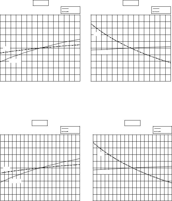
[5] Capacity/Input Ratio against Changes in Room Airflow Rate
• Model PRH-P8MYA/P200MYA
1.1
ratio |
|
Capacity/Input |
1 |
|
0.9
55
Cooling |
|
|
|
|
|
Heating |
|
|
|
Capacity |
|
|
|
|
Capacity |
|
|
Input |
|
|
|
|
Input |
|
|
|
1.1 |
|
|
|
|
|
|
|
|
|
Input |
|
|
|
|
|
ratio |
|
|
|
|
Input |
|
|
Capacity/Input |
1 |
|
|
|
|
|
|
|
|
|
||
|
|
|
|
|
Capacity |
|
|
Capacity |
|
|
|
|
|
|
|
65 |
75 |
85 |
0.9 |
|
|
|
|
|
55 |
65 |
75 |
85 |
|||
Airflow rate (m3/min) |
|
|
|
|
Airflow rate (m3/min) |
|
|
• Model |
PRH-P10MYA/P250MYA |
|
|
|
|
|
|
|
|
|
|
Cooling |
|
|
|
|
Heating |
|
|
|
|
|
|
Capacity |
|
|
|
|
Capacity |
|
|
|
|
Input |
|
|
|
|
Input |
1.1 |
|
|
|
|
1.1 |
|
|
|
|
Capacity/Inputratio |
|
|
|
|
Capacity/Inputratio |
Input |
|
|
|
Input |
|
|
|
|
|
|
|
||
1 |
|
|
|
1 |
Capacity |
|
|
|
|
|
|
|
|
|
|
|
|
|
|
|
Capacity |
|
|
|
|
|
|
|
|
0.9 |
|
|
|
|
0.9 |
|
|
|
|
70 |
80 |
90 |
100 |
110 |
70 |
80 |
90 |
100 |
110 |
Airflow rate (m3 /min) |
Airflow rate (m3 /min) |
- 23 -
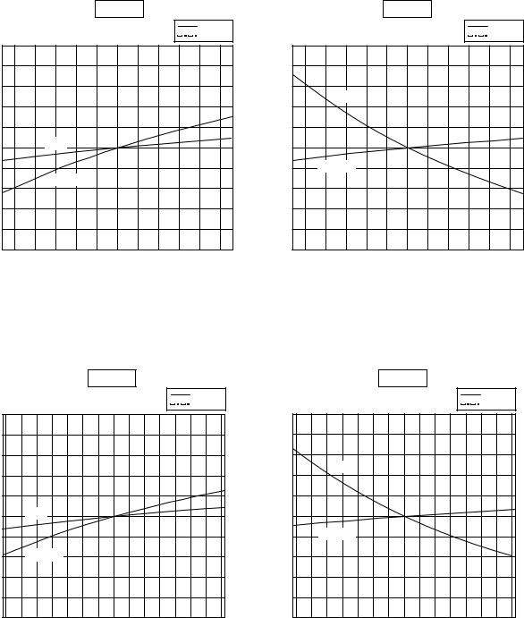
• Model |
PRH-P16MYA/P400MYA |
|
|
|
|||
|
|
|
|
Cooling |
|
|
|
|
|
|
|
|
|
Capacity |
|
1.1 |
|
|
|
|
Input |
|
|
|
|
|
|
|
|
||
ratio |
|
|
|
|
|
|
|
Capacity/Input |
1 |
|
Input |
|
|
|
|
|
|
|
|
|
|
||
|
|
Capacity |
|
|
|
|
|
|
|
|
|
|
|
|
|
0.9 |
|
|
|
|
|
|
|
|
112 |
120 |
130 |
140 |
150 |
160 |
168 |
|
|
|
Airflow rate (m3/min) |
|
|
|
|
• Model |
PRH-P20MYA/P500MYA |
|
|
|
|||||
|
|
|
|
|
Cooling |
|
|
|
|
|
|
|
|
|
|
|
|
Capacity |
|
|
|
|
|
|
|
|
|
Input |
|
1.1 |
|
|
|
|
|
|
|
|
|
ratio |
|
|
|
|
|
|
|
|
|
Capacity/Input |
1 |
Input |
|
|
|
|
|
|
|
|
|
|
|
|
|
|
|
||
|
|
Capacity |
|
|
|
|
|
|
|
|
|
|
|
|
|
|
|
|
|
0.9 |
|
|
|
|
|
|
|
|
|
|
144 |
150 |
160 |
170 |
180 |
190 |
200 |
210 |
216 |
Airflow rate (m3 /min)
Heating
Capacity Input
1.1
|
Input |
ratio |
|
Capacity/Input |
1 |
Capacity |
|
|
0.9 |
|
|
|
|
|
|
112 |
120 |
130 |
140 |
150 |
160 |
168 |
Airflow rate (m3/min)
Heating
Capacity Input
1.1
|
Input |
ratio |
|
Capacity/Input |
1 |
|
|
|
Capacity |
0.9 |
|
|
|
|
|
|
|
|
144 |
150 |
160 |
170 |
180 |
190 |
200 |
210 |
216 |
Airflow rate (m3 /min)
- 24 -
MYA, PRH-P10(250)MYA, PRH-P16(400)MYA, PRH-P20(500)MYA Service Manual")
[6] |
Bypass Factor Curves |
|
|
|
|
|
|
|
|
|
|||
|
|
|
PRH-P8MYA/P200MYA |
|
|
|
|
|
PRH-P10MYA/P250MYA |
|
|||
|
0.30 |
|
|
|
|
|
|
|
0.30 |
|
|
|
|
|
0.25 |
|
|
|
|
|
|
|
0.25 |
|
|
|
|
factor |
0.20 |
|
|
|
|
|
|
factor |
0.20 |
|
|
|
|
Bypass |
|
|
|
|
|
|
Bypass |
|
|
|
|
||
|
|
|
|
|
|
|
|
|
|
|
|
||
|
0.15 |
|
|
|
|
|
|
|
0.15 |
|
|
|
|
|
0.10 |
|
|
|
|
|
|
|
0.10 |
|
|
|
|
|
55 |
60 |
65 |
70 |
75 |
80 |
85 |
|
70 |
80 |
90 |
100 |
110 |
|
|
|
Airflow rate (m3/min) |
|
|
|
|
|
|
Airflow rate (m3/min) |
|
|
|
PRH-P16MYA/P400MYA |
|
PRH-P20MYA/P500MYA |
Bypass factor
0.2
0.15
0.1
0.05 |
|
|
|
|
|
|
112 |
120 |
130 |
140 |
150 |
160 |
168 |
Airflow rate (m3/min)
Bypass factor
0.3
0.25
0.2
0.15
0.1 |
|
|
|
|
|
|
|
|
144 |
150 |
160 |
170 |
180 |
190 |
200 |
210 |
216 |
Airflow rate (m3/min)
[7] Cooling Sensible Heating Capacity Table |
|
|
|
|
|
||||||
(1) PRH-P8MYA/P200MYA (Airflow rate 70m3/min) |
|
|
|
|
(unit : kcal/h) |
||||||
|
|
|
|
|
|
|
|
|
|||
|
|
|
|
|
|
|
|
|
|
|
|
Outdoor |
|
|
|
Indoor inlet air temperature (DB/WB°C) |
|
|
|
||||
|
|
|
|
|
|
|
|
|
|
||
temp. |
23/16 |
25/18 |
27/19 |
28/20 |
30/22 |
||||||
(°C) |
|
|
|
|
|
|
|
|
|
|
|
CA |
SHC |
CA |
SHC |
CA |
SHC |
CA |
SHC |
CA |
SHC |
||
|
|||||||||||
|
|
|
|
|
|
|
|
|
|
|
|
20 |
18100 |
14400 |
19300 |
14300 |
20000 |
15300 |
20800 |
15300 |
21900 |
15000 |
|
|
|
|
|
|
|
|
|
|
|
|
|
25 |
17500 |
14100 |
18700 |
14100 |
19500 |
15100 |
20300 |
15100 |
21500 |
14900 |
|
|
|
|
|
|
|
|
|
|
|
|
|
30 |
16900 |
13900 |
18100 |
13800 |
18900 |
14800 |
19700 |
14900 |
20900 |
14700 |
|
|
|
|
|
|
|
|
|
|
|
|
|
35 |
16200 |
13600 |
17400 |
13500 |
18000 |
14500 |
19000 |
14600 |
20200 |
14400 |
|
|
|
|
|
|
|
|
|
|
|
|
|
40 |
15300 |
13200 |
16600 |
13200 |
17400 |
14200 |
18200 |
14300 |
19500 |
14200 |
|
|
|
|
|
|
|
|
|
|
|
|
|
43 |
14800 |
12900 |
16000 |
12900 |
16900 |
14000 |
17700 |
14100 |
19000 |
14000 |
|
|
|
|
|
|
|
|
|
|
|
|
|
- 25 -
 Loading...