


Mitsubishi PUH-1.6VKA2, PUH-2VKA2, PUH-2.5VKA2, PUH-3VKA2, PUH-3YKA2 Service Manual
...
|
|
|
|
|
|
|
|
|
|
|
|
|
|
|
|
|
|
|
|
|
|
|
|
|
|
|
|
|
|
|
|
|
|
|
|
|
|
|
|
|
|
|
|
|
|
|
|
|
|
|
|
|
|
|
|
|
|
|
|
|
|
|
|
|
|
|
|
|
|
|
|
|
|
|
|
|
|
|
|
|
|
|
|
|
|
|
|
|
|
|
|
|
|
|
|
|
|
|
|
|
|
|
|
|
|
|
|
|
|
|
|
|
|
|
|
|
|
|
|
|
|
|
|
|
|
|
|
|
|
|
|
|
|
|
|
|
|
|
|
|
|
|
|
|
|
|
|
|
1997 |
|
|||||||||||||||||
|
|
|
|
|
|
|
|
|
|
|
|
|
|
|
|
|
|
|
|
|
|||||||||||||||||||||
|
|
|
|
|
|
|
|
|
|
|
|
|
|
|
|
|
|
|
|
|
|||||||||||||||||||||
|
|
|
|
|
|
|
|
|
|
|
|
|
|
|
|
|
|
|
|
|
|||||||||||||||||||||
|
|
|
|
|
|
|
|
|
|
|
|
|
|
|
|
|
|
|
|
|
|||||||||||||||||||||
|
|
|
|
|
|
|
|
|
|
|
|
|
|
|
|
|
|
|
|
|
|||||||||||||||||||||
|
|
|
|
|
|
|
|
|
|
|
|
|
|
|
|
|
|
|
|
||||||||||||||||||||||
|
|
|
|
|
|
|
|
|
|
|
|
|
|
|
|
|
|
|
|
||||||||||||||||||||||
|
|
|
|
|
|
|
|
|
|
|
|
|
|
|
|
|
|
|
|
||||||||||||||||||||||
SPLIT-TYPE, HEAT PUMP AIR CONDITIONERS |
|||||||||||||||||||||||||||||||||||||||||
|
|
|
|
|
|
|
|
|
|
|
|
|
|
|
|
|
|
|
|
|
|||||||||||||||||||||
|
|
|
|
|
|
|
|
|
|
|
|
|
|
|
|
|
|
|
|
|
|
|
|
|
|
|
|
|
|
|
|
|
|
|
|
|
|
|
|
|
|
|
|
|
|
|
|
|
|
|
|
|
|
|
|
|
|
|
|
|
|
|
|
|
|
|
|
|
|
|
|
|
|
No.OC128 |
|||||||||
TECHNICAL & SERVICE MANUAL
Outdoor unit |
|
[model names] |
[Service Ref.] |
PUH-1.6VKA |
PUH-1.6VKA2 |
PUH-2VKA |
PUH-2VKA2 |
PUH-2.5VKA |
PUH-2.5VKA2 |
PUH-3VKA |
PUH-3VKA2 |
PUH-3YKA |
PUH-3YKA2 |
PUH-4YKSA |
PUH-4YKSA3 |
PUH-5YKSA |
PUH-5YKSA3 |
PUH-6YKSA |
PUH-6YKSA2 |
CONTENTS
1. COMBINATION OF INDOOR AND OUTDOOR UNITS ·····2
2. PART NAMES AND FUNCTIONS·····················3
3. DATA··················································· ···············4
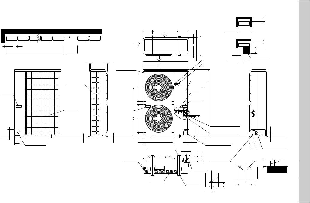
4. OUTLINES AND DIMENSIONS ························5
5. WIRING DIAGRAM ···········································9
6. REFRIGERANT SYSTEM DIAGRAM················16
7. DISASSEMBLY PROCEDURE ·······················17
8. PARTS LIST ··················································· ·19
9. OPTIONAL PARTS ··························Back cover
OUTDOOR UNIT
PUH-3K
The Slim Line.
From Mitsubishi Electric.
1 COMBINATION OF INDOOR AND OUTDOOR UNITS
Indoor unit |
|
|
|
|
Outdoor unit |
|
|
|
||
Service Ref. |
Service |
1.6 |
2 |
2.5 |
|
3 |
4 |
5 |
6 |
|
Manual No. |
VKA2 |
VKA2 |
VKA2 |
VKA2 |
YKA2 |
YKSA3 |
YKSA3 |
YKSA3 |
||
PLH-GKH(S)B1 |
||||||||||
OC139 |
— |
— |
— |
|
|
|
|
|
||
PLH-KKHC |
OC123 |
|
|
|
— |
— |
— |
— |
— |
|
PCH-GKH(S)A1 |
OC135 |
— |
|
|
|
|
|
|
|
|
PEH-EKH(S)A2.TH |
OC153 |
— |
— |
|
|
|
|
|
|
|
PKH-FKH(S)A3 |
OC130 |
|
|
|
|
|
|
— |
— |
|
PSH-GJH(S)A1 |
OC142 |
— |
— |
— |
|
|
|
|
|
|
2
2 PART NAMES AND FUNCTIONS
Air outlet
(Expels warm air during cooling)
Air intake
Air intake
PUH-1.6VKA2
PUH-2VKA2
Air outlet
Air intake
Air intake
PUH-4YKSA3
Air outlet
PUH-2.5VKA2
PUH-3YKA2
PUH-3VKA2
Air outlet
PUH-5YKSA3
PUH-6YKSA2
CHARGELESS SYSTEM
PRE-CHARGED REFRIGERANT IS SUPPLIED FOR MAXIMUM PIPING LENGTH AT SHIPMENT.
The unique refrigerant circuit and a large accumulator always control the optimal refrigerant level regardless of the length (30m max. and 5m min.) of piping. The additional refrigerant charging work during installation often causes problems. Heretofore it is completely eliminated. This unique system improves the quality and reliability of the work done. It also helps to speed up the installation time.
3
3 |
|
|
DATA |
|
|
|
|
|
|
|
|
|
|
|
|
|
|
|
|
|
|
|
|
|
|
||||
|
|
|
|
|
|
|
|
|
|
|
|
|
|
|
|
|
|
|
|
|
|
|
|
|
|
|
|
|
|
1. REFILLING REFRIGERANT CHARGE (R-22 : kg) |
|
|
|
|
|
|
|
|
|
|
|||||||||||||||||||
|
|
|
|
|
|
|
|
|
|
|
|
|
|
|
|
|
|
|
|
|
|
|
|
|
|
|
|
||
Service Ref. |
|
|
|
|
|
|
|
|
|
|
Refrigerant piping length (one way) |
|
|
|
|
|
|||||||||||||
|
|
|
|
|
|
|
|
|
|
|
|
|
|
|
|
|
|
|
|
|
|
|
|
||||||
|
|
5m |
|
10m |
|
15m |
|
20m |
|
25m |
|
30m |
|
35m |
|
40m |
45m |
50m |
|||||||||||
|
|
|
|
|
|
|
|
|
|
|
|
|
|
|
|||||||||||||||
|
|
|
|
|
|
|
|
|
|
|
|
|
|
|
|
|
|
|
|
|
|
|
|
|
|
|
|||
PUH-1.6VKA |
|
|
|
1.5 |
|
1.7 |
|
1.8 |
|
|
1.9 |
2.1 |
|
2.2 |
|
2.3 |
|
2.4 |
|
— |
— |
||||||||
|
|
|
2 |
|
|
|
|
|
|
|
|
|
|
|
|
|
|
|
|
|
|
|
|
|
|
|
|
|
|
PUH-2VKA2 |
|
|
|
1.5 |
|
1.7 |
|
1.8 |
|
|
1.9 |
2.1 |
|
2.2 |
|
2.3 |
|
2.4 |
|
— |
— |
||||||||
|
|
|
|
|
|
|
|
|
|
|
|
|
|
|
|
|
|
|
|
|
|
|
|
|
|
|
|||
PUH-2.5VKA |
|
|
|
2.1 |
|
2.3 |
|
2.4 |
|
|
2.5 |
2.7 |
|
2.8 |
|
2.9 |
|
3.0 |
|
3.1 |
3.3 |
||||||||
|
|
|
2 |
|
|
|
|
|
|
|
|
|
|
|
|
|
|
|
|
|
|
|
|
|
|
|
|
|
|
PUH-3VKA2 |
|
|
|
2.5 |
|
2.7 |
|
2.8 |
|
|
2.9 |
3.1 |
|
3.2 |
|
3.3 |
|
3.4 |
|
3.6 |
3.7 |
||||||||
|
|
|
|
|
|
|
|
|
|
|
|
|
|
|
|
|
|
|
|
|
|
|
|
|
|
|
|||
PUH-3YKA2 |
|
|
|
2.5 |
|
2.7 |
|
2.8 |
|
|
2.9 |
3.1 |
|
3.2 |
|
3.3 |
|
3.4 |
|
3.6 |
3.7 |
||||||||
|
|
|
|
|
|
|
|
|
|
|
|
|
|
|
|
|
|
|
|
|
|
|
|
|
|
|
|||
PUH-4YKSA |
|
|
|
3.5 |
|
3.6 |
|
3.8 |
|
|
3.9 |
4.1 |
|
4.2 |
|
4.4 |
|
4.5 |
|
4.6 |
4.8 |
||||||||
|
|
|
3 |
|
|
|
|
|
|
|
|
|
|
|
|
|
|
|
|
|
|
|
|
|
|
|
|
|
|
PUH-5YKSA |
|
|
|
4.7 |
|
4.8 |
|
5.0 |
|
|
5.1 |
5.3 |
|
5.4 |
|
5.6 |
|
5.7 |
|
5.9 |
6.0 |
||||||||
|
|
|
3 |
|
|
|
|
|
|
|
|
|
|
|
|
|
|
|
|
|
|
|
|
|
|
|
|
|
|
PUH-6YKSA |
|
|
|
4.3 |
|
4.4 |
|
4.6 |
|
|
4.7 |
4.9 |
|
5.0 |
|
5.2 |
|
5.3 |
|
5.5 |
5.6 |
||||||||
|
|
|
2 |
|
|
|
|
|
|
|
|
|
|
|
|
|
|
|
|
|
|
|
|
|
|
|
|
|
|
2. COMPRESSOR TECHNICAL DATA |
|
|
|
|
|
|
|
|
|
|
|
at 20˚C |
|
|
|||||||||||||||
|
|
|
|
|
|
|
|
|
|
|
|
|
|
|
|
||||||||||||||
Compressor Model |
|
RH247VFC |
NH38VMD |
|
NH41VMD |
|
NH52VND |
|
NH52YDA |
|
NH56YDA |
|
|
|
|||||||||||||||
|
|
|
|
|
|
|
|
|
|
|
|
|
|
|
|
|
|
|
|
|
|
|
|
|
|
|
|
|
|
|
|
|
|
|
U-V |
|
2.00 |
|
1.05 |
|
1.03 |
|
0.83 |
|
|
|
3.60 |
|
3.50 |
|
|
|
|||||||
Winding |
|
|
(R-C) |
|
|
|
|
|
|
|
|
|
|
|
|||||||||||||||
|
|
|
|
|
|
|
|
|
|
|
|
|
|
|
|
|
|
|
|
|
|
|
|
|
|||||
|
|
U-W |
|
|
|
|
|
|
|
|
|
|
|
|
|
|
|
|
|
|
|
|
|
|
|
||||
Resistance |
|
|
4.55 |
|
2.23 |
|
2.22 |
|
2.03 |
|
|
|
3.60 |
|
3.50 |
|
|
|
|||||||||||
|
(S-C) |
|
|
|
|
|
|
|
|
|
|
|
|||||||||||||||||
(Ω ) |
|
|
|
|
|
|
|
|
|
|
|
|
|
|
|
|
|
|
|
|
|
|
|
|
|
||||
|
|
W-V |
|
— |
|
|
— |
|
|
|
— |
|
— |
|
|
3.60 |
|
3.50 |
|
|
|
||||||||
|
|
|
|
|
|
|
|
|
|
|
|
|
|
|
|
|
|
||||||||||||
|
|
|
|
|
|
|
|
|
|
|
|
|
|
|
|
|
|
|
|
|
|
|
|
|
|
|
|
||
|
|
|
|
|
|
|
|
|
|
|
|
|
|
|
|
|
|
at 25˚C |
|
|
|
|
|
|
|
|
|||
|
|
|
|
|
|
|
|
|
|
|
|
|
|
|
|
||||||||||||||
Compressor Model |
|
ZR61K3TFD |
|
|
|
ZR68KCTFD |
|
|
|
|
|
|
|
|
|
|
|||||||||||||
|
|
|
|
|
|
|
|
|
|
|
|
|
|
|
|
|
|
|
|
|
|
|
|||||||
Winding |
|
|
T1-T2 |
|
2.53-2.91 |
|
|
|
2.31 |
|
|
|
|
|
|
|
|
|
|
|
|||||||||
|
|
|
|
|
|
|
|
|
|
|
|
|
|
|
|
|
|
|
|
|
|
|
|
|
|
|
|||
|
|
|
|
|
|
|
|
|
|
|
|
|
|
|
|
|
|
|
|
|
|
|
|
|
|
|
|||
Resistance |
T2-T3 |
|
2.53-2.91 |
|
|
|
2.31 |
|
|
|
|
|
|
|
|
|
|
|
|||||||||||
(Ω ) |
|
|
|
|
|
|
|
|
|
|
|
|
|
|
|
|
|
|
|
|
|
|
|
|
|
|
|
||
|
|
T3-T1 |
|
2.53-2.91 |
|
|
|
2.31 |
|
|
|
|
|
|
|
|
|
|
|
||||||||||
|
|
|
|
|
|
|
|
|
|
|
|
|
|
|
|
|
|
|
|
||||||||||
|
|
|
|
|
|
|
|
|
|
|
|
|
|
|
|
|
|
|
|
|
|
|
|
|
|
|
|
|
|
4
|
|
|
|
|
|
|
|
Outdoor Unit-Necessary surrounding clearance |
6VKAPUH.1- |
||
Outdoor Unit-Necessary surrounding clearance |
185 |
|
185 |
|
|
|
|
200 |
|||
(Concentrated installation) |
The upper side must be open. |
(7-9/32) |
500(19-11/16) |
(7-9/32) |
330(13)17 |
1/4)-362(14 |
10 |
Note:Allow adequate |
22VKA-/PUH2 |
||
|
|
200 |
|
|
27.539.5 |
500 |
150 |
||||
|
|
|
|
Air intake |
|
|
|
10 |
10 |
upper clearance |
|
|
|
|
|
|
|
|
|
|
Front opening |
|
|
|
|
|
Air intake |
|
|
|
|
|
|
|
|
100 |
10 |
|
|
|
|
|
|
|
|
|
|
For 10 units or less |
1000 |
Air outlet |
15 |
|
500 |
Service space |
|
|
|||||||
|
|
|
|
|
|||
|
|
|
|
|
|
|
|
Handle |
|
|
|
for moving |
|
7 295(11-5/8) 24(1) |
|
|
|
Outlet guide |
|
|
|
|
|
|
|
|
installation hole |
|
Rear fresh |
|
|
|
air intake |
Handle for moving |
|
|
|
||
|
Side air intake |
|
524 |
|
|
|
|
138 |
|
|
339 |
|
|
77 |
|
95 |
23 |
33 |
40 |
|
Rear piping hole |
|
|
Drain hole
5
870(34-1/4)
302
524
2-12 23 Oval holes (standard bolt M10)
Drain hole
Terminal block for indoor and outdoor unit connection
Terminal block for power line
Ground terminal
Handle for moving
Service panel |
|
|
|
|||
|
|
|
5/8)- |
connection |
|
|
|
|
|
|
Refrigerant-pipe flared |
|
|
|
|
|
(25 |
[15.88 3/8F |
|
|
282 |
297 |
444 |
650 |
[9.52 3/8F |
|
45 |
|
|
|
|
Refrigerant-pipe flared |
|
|
|
|
|
|
connection |
|
|
60 |
|
|
Knock out hole |
60 |
53 |
|
|
|
Knock out holes for |
||||
|
|
for front piping |
||||
|
|
|
|
|||
|
|
|
(refrigerant,drainage |
120 power line 2-[27 |
||
|
|
|
and wiring) |
|
|
|
104
|
33 |
42 |
45 |
|
||||
|
|
|
|
|
|
|
|
|
|
|
|
|
|
|
|
|
|
|
|
|
|
|
|
|
|
|
|
|
|
|
|
|
|
|
|
|
|
|
|
|
|
|
|
|
Bottom piping hole
2-U-shaped notched holes
Knock out hole |
|
for right piping |
|
(refrigerant,drainage |
|
and wiring) |
R |
|
20 |
R6 |
|
17 |
65 |
|
R20
80 |
25 max. |
|
|
Standard bolt length
12 |
|
|
|
|
Front right piping holes- |
|
|
|
|
detail figures |
|
|
|
|
|
|
(inch) mm : Unit
DIMENSIONS AND OUTLINES 4
6
Outdoor Unit-Necessary surrounding clearance
(Concentrated installation) The upper side must be open.
100 |
200 |
10 |
For 10 units or less |
1000 |
Air intake
185 |
185 |
(7-9/32) 500(19-11/16) |
(7-9/32) |
Air intake
Air outlet
17 |
|
||
39.5 27.5 |
|
330(13) |
362(14-1/4) |
|
|||
|
|||
|
|
|
|
15 |
|
||
|
|
|
|
Outdoor Unit-Necessary surrounding clearance
200
Note:Allow adequate 10 
 10 upper clearance
Front opening
500 |
150 |
10 |
|
Service space |
|
500 |
|
23YKA-/PUH23VKA-PUH |
25VKA.2-PUH |
Handle for moving
138
95
|
7 295(11-5/8) 24(1) |
|
|
Outlet guide |
|
Side air intake |
installation hole |
|
|
|
|
Rear fresh |
|
|
air intake |
Handle for moving |
|
|
|
|
|
|
524 |
|
441 |
|
|
|
179 |
23 |
33 |
40 |
Rear piping hole
Drain hole
870(34-1/4)
302
403
524
2-12 23 Oval holes (standard bolt M10)
Drain hole
Terminal block for indoor and outdoor unit connection
Terminal block for power line
Ground |
|
|
|
|
||
terminal |
|
|
|
|
||
Handle for moving |
|
|
|
|||
Service panel |
|
|
|
|||
|
|
553 |
850(33-7/16) Refrigerant-pipe flared |
|
|
|
337 |
352 |
|
connection [15.88 5/8F |
|
45 |
|
|
Refrigerant-pipe flared |
|
||||
|
|
|
connection [9.52 3/8F |
|
|
|
60 |
|
Knock out hole |
|
60 |
53 |
|
|
|
Knock out holes for |
||||
|
for front piping |
|
||||
|
|
|
|
120 |
||
|
|
|
(refrigerant,drainage |
power line 2-[27 |
||
|
|
|
and wiring) |
|
|
|
104 |
|
|
Knock out hole |
|
|
|
33 |
42 |
45 |
|
|
|
|
for right piping |
|
|
|
|||
|
|
|
|
|
|
|
|
|
|
(refrigerant,drainage |
R20 |
|
|
|
|
|
and wiring) |
R |
|
|
|
|
|
|
|
||
Bottom |
|
20 |
|
|
||
|
|
80 |
max.25 |
|||
piping hole |
|
|||||
|
|
|
||||
2-U-shaped |
|
|
R6 |
|
|
|
|
|
|
|
|
|
Standard bolt length |
|
|
|
|
|
|
|
|
|
|
|
|
|
|
||
notched |
|
|
|
|
|
|
|
|
|
|
|
|
|
|
|
|
|
|
|
|
|
|
65 |
|
|
|
|||
holes |
|
|
|
|
17 |
|
|
|
|
|
|
|
|
|
|
|
|
|
|
|
|
|
|
|
|
|
|
|
|
|
12 |
|
|
|
|
|
Front right piping holes- |
|||||||
|
|
|
|
|
|
|||||||||
|
|
|
|
|
|
detail figures |
||||||||
|
|
|
|
|
|
|
||||||||
(inch) mm : Unit

Outdoor Unit-Necessary surrounding clearance |
Outdoor Unit-Necessary surrounding clearance |
|||
(Concentrated installation) |
300 |
|
|
|
|
|
|||
The upper side must be open. |
|
|
||
|
|
|
|
|
|
|
|
|
|
|
|
|
|
|
|
185 |
|
185 |
|
|
|
Note:Allow adequate |
|
|
|
|
|
|
(7-9/32) |
500(19-11/16) |
(7-9/32) |
|
|
|
|
|
|
|
|
|
|
17 |
10 |
10 |
upper clearance |
|||
|
|
|
|
|
|
|
Air intake |
|
||||
|
|
|
|
|
|
|
|
|
Front opening |
|
||
|
|
|
|
|
|
|
|
|
|
|
||
|
|
|
|
|
|
|
|
39.527.5 |
330(13) |
362(14-1/4) |
100 |
|
|
For 10 units or less |
1000 |
|
|
|
|
|
500 |
||||
150 |
10 |
300 |
|
|
|
|
|
|
|
|
|
|
|
|
|
Air intake |
|
|
|
|
|
|
|
||
|
|
|
|
|
|
|
|
|
|
|
|
|
|
|
|
|
|
|
|
|
|
|
Terminal block for |
10 |
|
|
|
|
|
|
|
|
|
|
|
indoor and outdoor |
|
|
|
|
|
|
|
|
Air outlet |
|
|
|
Service space |
||
|
|
|
|
|
|
|
|
15 |
unit connection |
|||
|
|
|
|
|
|
870(34-1/4) |
|
500 |
|
|||
|
|
7 |
295(11-5/8) |
24(1) |
|
|
|
|
|
|||
|
|
Outlet guide |
302 |
|
|
|
Terminal block for power line |
|
||||
|
|
|
|
|
|
|
|
|
|
|
||
|
|
|
|
|
|
|
|
|
|
|
|
|
|
|
|
|
|
installation hole |
|
|
|
|
|
|
|
|
Side air intake |
|
|
Service panel |
|
||
|
|
|
|
|
|
|
|
Handle |
|
|
524 |
Ground |
|
|
|
|
|
terminal |
|
|
|||
for moving |
|
|
|
|
|||
|
|
|
Handle |
|
|
||
|
|
585 |
|
1/2)- |
|
||
|
|
|
for moving |
|
|||
|
|
|
|
1258(49 |
|
||
|
Rear fresh |
|
61 |
|
959 |
|
|
|
|
|
|
|
|
|
|
|
air intake |
Handle for moving |
|
|
|
|
|
|
|
|
|
|
|
|
|
|
|
|
524 |
|
|
Refrigerant-pipe flared |
|
|
|
|
|
|
|
|
|
|
|
345 |
|
382 |
403 |
connection [19.05 3/4F |
45 |
138 |
|
83 |
Refrigerant-pipe flared |
||||
|
|
|
|
connection [9.52 3/8F |
|
||
|
|
|
|
|
|
|
|
95
Rear piping hole
23 |
33 |
40 524
2-12 23 Oval holes (standard bolt M10)
Drain hole
Drain hole
60 |
|
Knock out hole |
||
|
for front piping |
|||
|
|
|
||
104 |
|
|
(refrigerant,drainage |
|
|
|
and wiring) |
||
39 |
52 |
57 |
||
Knock out hole |
||||
|
|
|
||
|
|
|
for right piping |
|
Bottom
(refrigerant,
piping hole
drainage and wiring)
2-U-shaped |
R6 |
|
|
||
notched |
17 |
|
holes |
||
|
60 |
53 |
|
Knock out holes for |
||
120 |
||
power line 2-[27 |
R |
R20 |
20 |
|
80 |
25 max. |
|
|
Standard bolt length
65
12 |
|
|
|
|
|
Front right piping holes- |
|
|
|
|
|
|
detail figures |
|
|
7
34YKSA-PUH
(inch) mm : Unit
8
Outdoor Unit-Necessary surrounding clearance (Concentrated installation)
The upper side must be open.
150 |
300 |
10 |
Air intake
For 10 units or less |
1000 |
7 345(13-9/16) 24(1)
Outlet guide installation hole
|
Side air intake |
|
|
Handle |
|
|
524 |
|
|
|
|
for moving |
|
|
|
|
Rear fresh |
585 |
61 |
|
|
|
|
|
air intake |
Handle for moving |
|
|
|
|
|
|
|
345 |
524 |
|
|
|
|
138 |
|
|
83 |
95 |
23 |
33 |
90 |
|
Rear piping hole |
|
|
|
|
Drain hole |
|
|
|
|
|
|
|
|
Outdoor Unit-Necessary surrounding clearance |
||||
|
|
|
|
|
|
|
|
|
|
|
300 |
185 |
|
|
185 |
|
|
|
|
|
|
Note:Allow adequate |
|
(7-9/32) |
600(23-5/8) |
(7-9/32) |
|
|
|
|
|
|
|||
17 |
|
|
10 |
|
|
10 |
upper clearance |
||||
|
Air intake |
|
|
|
|
|
|
||||
|
|
|
|
|
|
|
Front opening |
|
|||
|
|
|
|
|
|
|
|
|
|||
|
|
|
|
|
|
|
|
|
|
||
|
|
|
39.5 27.5 |
380(14-31/32) |
|
412(16-1/4) |
|
|
|
500 |
150 |
|
|
|
|
|
|
Terminal block for |
10 |
|
|
|
|
|
|
|
|
|
|
indoor and outdoor |
|
|
|
||
Air outlet |
|
|
|
|
|
|
|
Service space |
|||
|
|
|
15 |
|
unit connection |
|
|
||||
970(38-3/16) |
|
|
|
|
500 |
|
|||||
|
|
|
Terminal block for power line |
|
|||||||
352 |
|
|
|
|
|
|
|
||||
|
|
|
|
|
|
|
|
|
|
|
|
|
|
|
Service panel |
|
|
|
|
||||
|
|
|
Ground |
|
|
|
|
|
|||
|
|
|
terminal |
|
|
|
|
|
|||
|
|
|
Handle |
1/2) |
|
|
|
|
|||
|
|
|
for moving |
|
|
|
|
||||
|
|
|
|
|
|
959 |
1258(49- |
|
|
|
|
|
|
|
|
|
|
|
Refrigerant-pipe flared |
|
|
||
|
|
|
382 |
403 |
connection [19.05 3/4F |
|
45 |
||||
|
|
|
Refrigerant-pipe flared |
|
|||||||
|
|
|
|
|
|
|
connection [9.52 3/8F |
|
|
||
|
524 |
|
60 |
|
|
Knock out hole |
|
|
60 |
53 |
|
|
|
|
|
|
|
Knock out holes for |
|||||
|
|
|
|
for front piping |
|
|
|||||
|
|
|
|
|
|
|
|
|
120 |
||
2-12 23 Oval holes |
|
104 |
|
|
|
(refrigerant,drainage |
|
|
power line 2-[27 |
||
|
|
|
|
|
|
|
|
||||
|
|
|
|
and wiring) |
|
|
|
|
|||
(standard bolt M10) |
|
|
|
|
|
|
|
|
|||
|
39 |
52 |
57 |
|
|
|
|
||||
|
|
|
|
|
|
||||||
|
|
|
Knock out hole |
|
|
|
|
||||
|
|
|
|
|
|
|
|
|
|
|
|
|
|
|
|
|
|
|
for right piping |
|
|
R20 |
|
|
|
|
|
|
|
|
(refrigerant, |
|
R |
|
|
|
|
|
Bottom |
|
20 |
|
|
||||
|
|
|
drainage and wiring) |
|
|
|
|||||
|
|
|
|
|
|
|
|
80 |
max.25 |
||
|
|
|
piping hole |
|
|
||||||
|
|
|
|
|
|
|
|||||
Drain hole |
|
2-U-shaped |
R6 |
|
|
|
Standard bolt length |
||||
|
|
|
|
|
|||||||
|
notched |
|
|
|
|
|
|||||
|
|
|
|
|
|
|
65 |
|
|||
|
|
|
holes |
|
|
|
17 |
|
|
|
|
|
|
|
|
|
|
|
|
|
|
||
|
|
|
|
|
|
|
|
|
|
|
|
|
|
|
|
|
|
|
12 |
|
Front right piping holes- |
||
|
|
|
|
|
|
|
|
detail figures |
|
||
|
|
|
|
|
|
|
|
|
|
||
26YKSA-/PUH35YKSA-PUH
(inch) mm : Unit
5 |
|
|
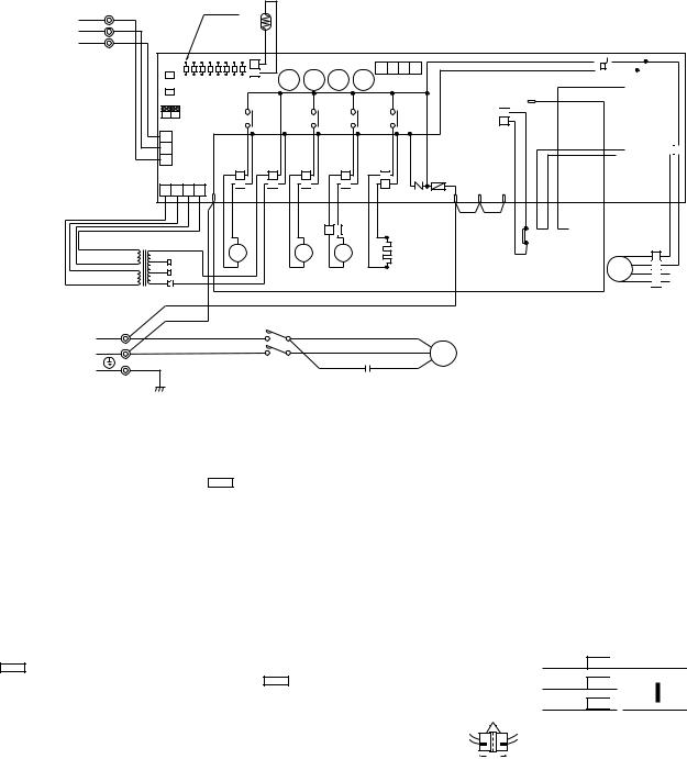
WIRING DIAGRAM |
|
|
|
|
|
|
|
|
|
|
|
|
PUH-1.6VKA2 |
|
|
|
|
|||
|
|
|
|
|
|
||
SYMBOL |
NAME |
SYMBOL |
NAME |
SYMBOL |
NAME |
||
HC |
CRANKCASE HEATER |
MC |
COMPRESSOR (INNER THERMOSTAT) |
X12<O.B> |
COMPRESSOR RELAY |
||
C1 |
OUTDOOR FAN CAPACITOR |
MF |
OUTDOOR FAN MOTOR (INNER THERMOSTAT) |
X13<O.B> |
21S4 RELAY |
||
C2 |
COMPRESSOR CAPACITOR |
O.B |
OUTDOOR CONTROLLER BOARD |
X14<O.B> |
21R RELAY |
||
FC<O.B> |
FAN CONTROLLER |
SW1·2·3<O.B> |
CHECK,SERVICE SELECTOR |
ZNR<O.B> |
VARISTER |
||
F<O.B> |
FUSE(6A) |
T |
TRANSFORMER |
52C |
CONTACTOR |
||
21S4 |
R.V.COIL |
TB1,3 |
TERMINAL BLOCK |
63H1 |
HIGH PRESSURE SWITCH |
||
21R |
B.V.COIL |
RT |
OUTDOOR COIL THERMISTOR |
|
|
||
(0˚C/15kΩ ,25˚C/5.4kΩ ) |
|
|
|||||
LD1~LD8 |
CHECK,SERVICE LED |
X11<O.B> |
HC RELAY |
|
|
||
|
1 |
YLW |
LED |
|
FROOM INDOOR UNIT |
RT |
|||
2 |
ORN |
|||
CONNECTING WIRES |
|
|||
3 |
BRN |
|
||
12V DC (polar) |
O.B |
|||
TB3 |
||||
|
||||
|
|
|||
|
|
SW1 |
|
|
|
|
|
|
|
|
|
4 3 2 1 |
|
|
|
|
||
|
|
SW2 |
LD1 LD2 LD3 LD4 LD5 LD6 LD7 LD8 |
CN2 |
14 |
13 |
12 |
11 |
CN4 |
|
|
S |
|
|||||
|
|
|
|
|
|
|
|
|
|
|
|
|
|
|
|
|||
|
|
SW2 OFF |
|
|
|
|
|
|
|
|
|
|
|
|
|
|||
|
|
|
|
|
|
|
|
|
|
|
|
63H1 |
|
|
|
|||
|
|
2 1 ON |
|
14 |
|
|
13 |
|
12 |
11 |
|
|
|
|||||
|
|
|
|
|
|
|
|
|
|
|||||||||
|
|
3 |
|
|
|
|
|
|
|
|
|
|
|
|
|
|
|
|
|
|
2 CN3 |
|
|
|
|
|
|
|
|
|
|
|
|
|
|
||
|
|
1 |
|
|
|
|
|
|
|
|
|
|
|
|
|
|
|
|
|
|
|
CN4T |
4 |
|
|
|
|
|
|
|
|
|
F |
|
|
|
|
|
|
4 3 2 1 |
TRF |
21S4 |
52C |
CH |
ZNR R/1 S/2 T/3 |
|
|
|
||||||||
|
|
|
|
|
SV |
BRN BRN |
63H1YLWYLW |
YLW |
||||||||||
|
|
|
|
|
RED RED |
WHT WHT |
RED RED |
|
GRY GRY |
|
GRY WHT WHT |
|
|
|
||||
|
|
|
|
|
|
|
|
|
|
|
S |
|
|
|
BLU BLU |
|
YLW |
|
|
|
|
|
|
|
|
|
21 |
GRY |
|
A |
|
|
|
|
|
|
|
|
|
RED |
|
|
21R |
|
|
52C |
|
|
HC |
|
|
|
|
|||
BRN 12.3V AC |
220V |
|
|
S4 |
|
|
|
|
|
|
|
|||||||
|
|
|
|
|
B |
|
|
|
|
|
|
|||||||
|
|
ORN |
|
|
|
|
|
|
|
|
|
|
|
|
||||
RED 12.3V AC |
YLW |
230V |
|
|
|
|
|
|
|
|
|
|
|
|
|
|
||
|
|
T |
240V |
|
|
|
|
|
|
|
|
|
|
|
|
|
|
|
|
|
|
RED |
|
|
|
|
|
|
|
|
|
|
|
|
|
||
|
|
|
|
|
|
|
|
|
|
|
|
|
|
|
|
|
||
|
TB1 |
|
|
BLK |
|
52C |
|
|
|
|
|
|
|
|
|
|
|
|
|
|
|
|
|
|
|
|
|
|
|
|
|
|
|
|
|||
POWER SUPPLY |
L |
|
|
RED |
R |
U |
BLU |
|
|
|
R |
|
|
|
|
|||
|
|
|
|
|
|
|
|
WHT |
|
|
|
|
|
|
||||
~/N(1phase) |
N |
|
|
BLK |
T |
W |
|
|
C |
MC |
|
|
|
|||||
|
|
|
|
|
BLU |
|
|
RED |
|
|
|
|||||||
220-240V 50Hz |
|
|
|
|
|
|
|
|
|
|
|
|||||||
|
|
|
|
|
|
|
|
|
|
|
|
|
|
|||||
|
GRY/YLW |
|
|
|
|
|
|
C2 |
|
S |
|
|
|
|
||||
|
|
|
|
|
|
|
|
|
|
|
|
|
|
|||||
|
|
|
|
|
|
|
|
|
|
|
|
|
|
|
||||
Main functions of LED (when both Nos. 1 and 2 of SW3 are ”OFF”)
LED No. |
Output display |
( |
light |
) |
Check display |
( |
flash |
) |
LD1 |
Compressor ON command from indoor |
— |
|
|
|
|||
LD2 |
Heating indoor command |
— |
|
|
|
|||
LD3 |
63H1 |
|
ON |
RT short/open |
|
|
|
|
LD4 |
Compressor |
|
ON |
— |
|
|
|
|
LD5 |
Outdoor fan |
|
ON |
— |
|
|
|
|
LD6 |
4-way valve |
|
ON |
26C functions |
|
|
|
|
LD7 |
Bypass valve |
|
ON |
RT overheat protection |
|
|||
LD8 |
Crankcase heater |
|
ON |
Defective input |
|
|
|
|
|
|
|
|
|
|
|
|
|
|
|
|
|
|
|
|
|
|
|
|
|
|
FC |
|
|
|
|
|
|
|
||||||||||||
|
|
|
|
|
|
|
|
|
|
|
|
|
|
|
|
|
|
|
|
|
|
|
|
|
|
|
|
|
|
|
|
|
|
|
|
|
|
|
|
||
|
|
|
|
|
|
26C |
|
|
|
|
|
MF2 |
|
|
||||||
|
|
|
|
|
|
|
|
|
|
|
|
|
|
|
|
|
|
|
||
|
|
|
|
|
|
|
|
|
|
|
|
|
|
|
|
|
|
|
|
|
|
|
|
|
|
|
|
|
|
|
|
|
|
|
|
|
|
|
|
|
|
|
|
|
|
|
63H2 |
|
|
|
MF1 |
|
|
|
||||||||
|
|
|
|
|
|
|
|
|
|
|
|
|
|
|
|
|
||||
|
|
|
|
|
|
|
|
|
|
|
|
|
|
|
|
|
|
|
||
|
|
|
|
|
51CM |
|
|
|
|
|
|
|
||||||||
BLU |
|
|
|
BLU WHT |
||||||||||||||||
|
|
|
|
|
|
|
|
|
|
|
|
|
|
|
|
|
|
|
|
|
BLU 4
WHT 3
MF RED 2 RED ORN
 C1 1 ORN
NOTE : If the operation stops and the protection device is functioning, the check display will flash.
How to use SW1 and 2
●Pressing SW1 erases the past check contents loaded on the microcomputer.
●The output display (light) remains lit during operation, but pressing SW2 displays the past check contents by a flashing mode. Pressing the switch again returns it to output display (light).
CAUTION FOR SERVICING
|
|
|
|
|
|
|
fig. 1 White connector |
||||
●The connector marked |
|
|
|
|
|
|
s turns the compressor ON and OFF during servicing. |
||||
|
|
|
|
|
|
|
|
|
|
|
|
The compressor stops when the white connector is disconnected. See fig.1.
fig. 2 When power supply is 220V
RED 220V
 WHITE ORANGE 230V

 YELLOW 240V

CAUTIONS FOR POWER SUPPLY WIRING
●Since LD8 lights when normal power is turned ”ON”, check the power supply with the ON or OFF LD8.
Since the indoor transformer (T) is connected with 240V power, using 220V or 230V power will require a wiring connection change. See fig.2.
CAUTION FOR INDOOR AND OUTDOOR CONNECTING WIRES
●Since the indoor and outdoor connecting wires have polarity, be sure to connect the same terminal numbers (1,2,3) for the indoor and outdoor units.
9
PUH-2VKA2/PUH-2.5VKA2
SYMBOL |
NAME |
SYMBOL |
NAME |
SYMBOL |
NAME |
CN3(O.B) |
CONNECTING WIRES |
MC |
COMPRESSOR (INNER THERMOSTAT) |
X12(O.B) |
MC RELAY |
|
INDOOR/OUTDOOR CONNECTOR |
MF |
OUTDOOR FAN MOTOR (INNER THERMOSTAT) |
X13(O.B) |
21S4 RELAY |
CN4T(O.B) |
TRANSFORMER CONNECTOR |
O.B |
OUTDOOR CONTROLLER BOARD |
X14(O.B) |
21R RELAY |
HC |
CRANKCASE HEATER |
21R |
BYPASS VALVE SOLENOID COIL |
ZNR(O.B) |
SURGE ABSORBER |
C1 |
OUTDOOR FAN CAPACITOR |
( ) |
CHECK,SERVICE SELECT SWITCH |
21S4 |
4-WAY VALVE SOLENOID COIL |
SW1·2·3O.B |
|||||
C2 |
COMPRESSOR CAPACITOR |
T |
TRANSFORMER |
52C |
CONTACTOR |
FC(O.B) |
FAN CONTROLLER |
TB1,3 |
TERMINAL BLOCK |
63H1 |
HIGH PRESSURE SWITCH |
F(O.B) |
FUSE(6,3A) |
RT |
OUTDOOR COIL THERMISTOR |
|
|
LD1-LD8 |
CHECK,SERVICE LED |
X11(O.B) |
HC RELAY |
|
|
TO INDOOR UNIT |
1 |
YLW |
LED |
RT |
|
|
|
|
|
|
|
|
|
|
|
|
|
|
|
|
|
|
|
|
2 |
ORN |
O.B. |
|
|
|
|
|
|
|
|
|
|
|
|
|
|
|
|
|
|
|
|
|
|
CONNECTING WIRES |
|
|
|
|
|
|
|
|
|
|
|
|
|
|
|
|
|
|
|
|
|
|||
3 |
BRN |
SW1 |
|
|
|
|
|
|
|
|
|
|
|
|
|
|
|
|
|
|
|
|
|
|
DC 12V |
|
|
|
|
|
|
|
|
|
|
|
|
|
|
|
|
|
|
|
|
|
|||
TB3 |
|
|
|
|
|
4 |
3 |
2 |
1 |
|
|
|
|
|
|
|
|
|
|
|
|
|
||
|
SW2 |
LD1 LD2 LD3 LD4 LD5 LD6 LD7 LD8 |
|
|
|
|
|
|
|
|
|
|
|
|
|
|
|
|||||||
|
|
|
SW3 |
|
|
|
CN4 |
|
|
|
|
|
|
|
|
|
|
|
|
|
|
|||
|
|
|
|
CN2 |
14 |
13 |
12 |
11 |
|
|
|
|
|
|
|
|
|
|
|
|
|
|||
|
|
|
OFF |
|
|
|
|
|
|
|
|
|
|
|
|
|
||||||||
|
|
|
21 ON |
|
|
|
|
|
|
|
|
|
|
|
|
|
|
|
|
|
|
|
|
|
|
|
|
3 |
CN3 |
|
|
|
|
|
|
|
|
|
|
|
|
|
|
|
|
|
|
|
|
|
|
|
2 |
|
14 |
|
13 |
|
12 |
11 |
|
|
26C |
|
F.C. |
|
|
|
|
|
||||
|
|
|
1 |
|
|
|
|
|
|
|
|
|
|
MF2 |
|
|
|
|
|
|||||
|
|
|
|
|
|
|
|
|
|
|
|
|
|
|
|
|
|
|
|
|
|
|
|
|
|
|
|
CN4T |
|
|
|
|
|
|
|
|
63H1 |
|
|
51CM |
|
|
|
MF1 |
|
|
|
||
|
|
|
4 3 2 1 |
|
|
|
|
|
|
|
|
|
|
|
|
|
|
|
|
|
|
|
||
|
|
|
|
|
|
|
|
|
|
|
|
|
|
|
|
|
|
|
|
|
|
|
||
|
|
|
|
4 |
TRF |
21S4 |
52C |
CH ZNR FR S |
T |
|
|
|
|
S |
|
|
|
|
|
|||||
|
|
RED |
|
|
SV |
|
|
|
|
|
|
|
|
|
||||||||||
|
|
BRN |
|
RED RED |
RED |
RED |
GRY |
GRY |
WHT WHT |
|
|
|
BRN BRN |
YLW |
YLW |
YLW YLW |
BLU |
BLU |
WHT |
|
|
|
||
|
|
RED |
|
|
|
|
|
|
|
|
|
|
|
|
|
|
|
|
|
|
|
|
|
|
|
|
|
BRN |
|
|
|
|
|
|
A1 |
|
|
BLUBLU |
|
|
|
|
|
|
|
3 WHT |
|
||
|
|
|
|
|
|
21 |
|
|
|
|
|
|
63H1 |
|
|
|
|
|
|
|||||
|
|
AC |
|
|
21R |
|
|
52C |
|
HC |
|
|
|
|
|
|
|
4 BLU |
|
|||||
|
|
RED |
|
|
|
|
|
|
|
|
|
|
|
|
|
|||||||||
|
|
12.3V |
|
220V |
|
|
S4 |
|
|
A2 |
|
|
|
|
|
|
|
|
|
RED |
2 RED |
MF |
||
|
|
|
ORN |
WHT |
|
|
|
|
|
|
|
|
|
|
|
|
|
C1 |
|
|
ORN |
|
||
|
|
|
|
230V |
|
|
|
|
|
|
|
|
|
|
|
|
|
|
ORN 1 |
|
|
|||
|
|
AC12.3V |
YLW |
WHT |
|
|
|
|
|
|
|
|
|
|
|
|
|
|
|
|
||||
|
|
|
T |
240V |
|
|
|
|
|
|
|
|
|
|
|
|
|
|
|
|
|
|
|
|
POWER SUPPLY |
|
|
RED |
|
|
|
|
|
|
|
|
|
|
|
|
|
|
|
|
|
|
|
|
|
|
|
|
BLU |
|
|
|
|
|
|
|
|
|
|
|
|
|
|
|
|
|
|
|
|
|
~/N |
|
|
|
|
|
|
|
|
|
|
|
|
|
|
|
|
|
|
|
|
|
|
|
|
220-240V 50Hz |
|
|
|
|
|
|
|
|
|
|
|
|
|
|
|
|
|
|
|
|
|
|
|
|
|
L TB1 |
|
|
RED |
|
L1/1 |
|
|
T1/2 |
BLU |
|
R |
|
|
|
|
|
|
|
|
|
|||
|
|
|
|
|
|
|
|
|
|
|
|
|
|
|
|
|
|
|
|
|
|
|
||
|
N |
|
|
|
BLU |
|
L3/5 |
|
|
|
|
WHT |
|
C |
MC |
|
|
|
|
|
|
|
|
|
|
|
|
|
|
|
|
52CT3/6 |
BLU |
RED |
|
|
|
|
|
|
|
|
|
||||||
|
|
|
|
|
|
|
S |
|
|
|
|
|
|
|
|
|
||||||||
|
|
|
GRN/YLW |
|
|
|
|
|
|
C2 |
|
|
|
|
|
|
|
|
|
|
|
|
||
|
|
|
|
|
|
|
|
|
|
|
|
|
|
|
|
|
|
|
|
|
|
|||
CAUTIONS FOR POWER SUPPLY WIRING
●Since LD8 lights when normal power is turned “ON”, check the power supply with the ON or OFF LD8.Since the transformer (T) is connected with 240V power, if 220V or 230V power is used, change the
wiring connection in the following procedure
CAUTION FOR INDOOR AND OUTDOOR CONNECTING WIRES
When power supply is 220V
RED |
220V |
|
|
|
|
WHITE |
|
|
|
|
|
||||
ORANGE |
|
|
|
|
|
|
|
|
|
|
|
|
|
|
|
230V |
|
|
|
|
|
|
|
YELLOW |
|
|
|
|
|
|
|
240V |
|
|
|
|
|
|
|
●Since the indoor and outdoor connecting wires has polarity, make sure to connect the same terminal numbers (1,2,3) for indoor and outdoor units.
Main functions of LED
|
( |
when both Nos.1 and 2 of |
SW3 |
) |
|
|
||||
|
|
are “OFF” |
|
|
||||||
|
|
|
|
|
|
|
|
|
|
|
LED No. |
Output display |
( |
light |
) |
|
( |
flash |
) |
||
|
|
|
|
Check display |
|
|||||
LD1 |
Compressor indoor command |
|
|
— |
|
|
||||
LD2 |
Heating indoor command |
|
|
— |
|
|
||||
LD3 |
63H1 |
|
|
ON |
|
Outdoor coil thermistor short/open |
||||
LD4 |
Compressor |
|
ON |
|
|
— |
|
|
||
LD5 |
Outdoor fan |
|
ON |
|
|
— |
|
|
||
LD6 |
4-way valve |
|
ON |
|
26C functions |
|
|
|||
LD7 |
Bypass valve |
|
ON |
|
RT overheat protection |
|
||||
LD8 |
Crankcase heater |
|
ON |
|
Defective input |
|
|
|||
NOTE :
If the operation stops to function of the protection device, the check display flashes.
How to use SW1 and 2
●Pressing SW1 erases the past check contents loaded on the microcomputer. ●The output display (light) remains during operation but pressing SW2 displays the
past check contents in flushing mode.
Pressing the switch again returns to output display (light).
10
PUH-3VKA2
SYMBOL |
NAME |
SYMBOL |
|
NAME |
SYMBOL |
NAME |
CN3(O.B) |
CONNECTING WIRES |
MC |
|
COMPRESSOR (INNER THERMOSTAT) |
X12(O.B) |
MC RELAY |
|
INDOOR/OUTDOOR CONNECTOR |
MF |
|
OUTDOOR FAN MOTOR (INNER THERMOSTAT) |
X13(O.B) |
21S4 RELAY |
CN4T(O.B) |
TRANSFORMER CONNECTOR |
O.B |
|
OUTDOOR CONTROLLER BOARD |
X14(O.B) |
21R RELAY |
HC |
CRANKCASE HEATER |
21R |
|
BYPASS VALVE SOLENOID COIL |
ZNR(O.B) |
SURGE ABSORBER |
C1 |
OUTDOOR FAN CAPACITOR |
( |
) |
CHECK,SERVICE SELECT SWITCH |
21S4 |
4-WAY VALVE SOLENOID COIL |
SW1·2·3O.B |
|
|||||
C2 |
COMPRESSOR CAPACITOR |
T |
|
TRANSFORMER |
52C |
CONTACTOR |
FC(O.B) |
FAN CONTROLLER |
TB1,3 |
|
TERMINAL BLOCK |
63H1 |
HIGH PRESSURE SWITCH |
F(O.B) |
FUSE(6,3A) |
RT |
|
OUTDOOR COIL THERMISTOR |
|
|
LD1-LD8 |
CHECK,SERVICE LED |
X11(O.B) |
|
HC RELAY |
|
|
TO INDOOR UNIT |
1 |
YLW |
LED |
RT |
|
|
|
|
|
|
|
|
|
|
|
|
|
|
|
|
|
|
|
|
2 |
ORN |
O.B. |
|
|
|
|
|
|
|
|
|
|
|
|
|
|
|
|
|
|
|
|
|
|
CONNECTING WIRES |
|
|
|
|
|
|
|
|
|
|
|
|
|
|
|
|
|
|
|
|
|
|||
3 |
BRN |
SW1 |
|
|
|
|
|
|
|
|
|
|
|
|
|
|
|
|
|
|
|
|
|
|
DC 12V |
|
|
|
|
|
|
|
|
|
|
|
|
|
|
|
|
|
|
|
|
|
|||
TB3 |
|
|
|
|
|
4 |
3 |
2 |
1 |
|
|
|
|
|
|
|
|
|
|
|
|
|
||
|
SW2 |
LD1 LD2 LD3 LD4 LD5 LD6 LD7 LD8 |
|
|
|
|
|
|
|
|
|
|
|
|
|
|
|
|||||||
|
|
|
SW3 |
|
|
|
CN4 |
|
|
|
|
|
|
|
|
|
|
|
|
|
|
|||
|
|
|
|
CN2 |
14 |
13 |
12 |
11 |
|
|
|
|
|
|
|
|
|
|
|
|
|
|||
|
|
|
OFF |
|
|
|
|
|
|
|
|
|
|
|
|
|
||||||||
|
|
|
21 ON |
|
|
|
|
|
|
|
|
|
|
|
|
|
|
|
|
|
|
|
|
|
|
|
|
3 |
CN3 |
|
|
|
|
|
|
|
|
|
|
|
|
|
|
|
|
|
|
|
|
|
|
|
2 |
|
14 |
|
13 |
|
12 |
11 |
|
|
26C |
|
F.C. |
|
|
|
|
|
||||
|
|
|
1 |
|
|
|
|
|
|
|
|
|
|
MF2 |
|
|
|
|
|
|||||
|
|
|
|
|
|
|
|
|
|
|
|
|
|
|
|
|
|
|
|
|
|
|
|
|
|
|
|
CN4T |
|
|
|
|
|
|
|
|
63H1 |
|
|
51CM |
|
|
|
MF1 |
|
|
|
||
|
|
|
4 3 2 1 |
|
|
|
|
|
|
|
|
|
|
|
|
|
|
|
|
|
|
|
||
|
|
|
|
|
|
|
|
|
|
|
|
|
|
|
|
|
|
|
|
|
|
|
||
|
|
|
|
4 |
TRF |
21S4 |
52C |
CH ZNR FR S |
T |
|
|
|
|
S |
|
|
|
|
|
|||||
|
|
RED |
|
|
SV |
|
|
|
|
|
|
|
|
|
||||||||||
|
|
BRN |
|
RED RED |
RED |
RED |
GRY |
GRY |
WHT WHT |
|
|
|
BRN BRN |
YLW |
YLW |
YLW YLW |
BLU |
BLU |
WHT |
|
|
|
||
|
|
RED |
|
|
|
|
|
|
|
|
|
|
|
|
|
|
|
|
|
|
|
|
|
|
|
|
|
BRN |
|
|
|
|
|
|
A1 |
|
|
BLUBLU |
|
|
|
|
|
|
|
3 WHT |
|
||
|
|
|
|
|
|
21 |
|
|
|
|
|
|
63H1 |
|
|
|
|
|
|
|||||
|
|
AC |
|
|
21R |
|
|
52C |
|
HC |
|
|
|
|
|
|
|
4 BLU |
|
|||||
|
|
RED |
|
|
|
|
|
|
|
|
|
|
|
|
|
|||||||||
|
|
12.3V |
|
220V |
|
|
S4 |
|
|
A2 |
|
|
|
|
|
|
|
|
|
RED |
2 RED |
MF |
||
|
|
|
ORN |
WHT |
|
|
|
|
|
|
|
|
|
|
|
|
|
C1 |
|
|
ORN |
|
||
|
|
|
|
230V |
|
|
|
|
|
|
|
|
|
|
|
|
|
|
ORN 1 |
|
|
|||
|
|
AC12.3V |
YLW |
WHT |
|
|
|
|
|
|
|
|
|
|
|
|
|
|
|
|
||||
|
|
|
T |
240V |
|
|
|
|
|
|
|
|
|
|
|
|
|
|
|
|
|
|
|
|
POWER SUPPLY |
|
|
RED |
|
|
|
|
|
|
|
|
|
|
|
|
|
|
|
|
|
|
|
|
|
|
|
|
BLU |
|
|
|
|
|
|
|
|
|
|
|
|
|
|
|
|
|
|
|
|
|
~/N |
|
|
|
|
|
|
|
|
|
|
|
|
|
|
|
|
|
|
|
|
|
|
|
|
220-240V 50Hz |
|
|
|
|
|
|
|
|
|
|
|
|
|
|
|
|
|
|
|
|
|
|
|
|
|
L TB1 |
|
|
RED |
|
L1/1 |
|
|
T1/2 |
BLU |
|
R |
|
|
|
|
|
|
|
|
|
|||
|
|
|
|
|
|
|
|
|
|
|
|
|
|
|
|
|
|
|
|
|
|
|
||
|
N |
|
|
|
BLU |
|
L3/5 |
|
|
|
|
WHT |
|
C |
MC |
|
|
|
|
|
|
|
|
|
|
|
|
|
|
|
|
52CT3/6 |
BLU |
RED |
|
|
|
|
|
|
|
|
|
||||||
|
|
|
|
|
|
|
S |
|
|
|
|
|
|
|
|
|
||||||||
|
|
|
GRN/YLW |
|
|
|
|
|
|
C2 |
|
|
|
|
|
|
|
|
|
|
|
|
||
|
|
|
|
|
|
|
|
|
|
|
|
|
|
|
|
|
|
|
|
|
|
|||
Main functions of LED (when both Nos.1 and 2 of |
SW3 |
are ”OFF” ) |
|
|
How to use SW1 and 2 |
|||||||||
|
|
|
|
|
|
|
|
●Pressing |
|
|
|
erases the past check contents loaded on the |
||
|
|
( |
) |
|
( |
|
) |
SW1 |
|
|||||
LED No. |
Output display |
light |
|
|
|
Check display |
flash |
|
microcomputer. |
|||||
LD1 |
Compressor indoor command |
|
|
— |
|
|
||||||||
|
|
|
|
●The output display (light) remains lit during operation but |
||||||||||
LD2 |
Heating indoor command |
|
|
|
— |
|
|
|||||||
|
|
|
|
|
pressing |
|
SW2 |
|
displays the past check contents in flashing |
|||||
LD3 |
63H1 |
ON |
|
|
Outdoor coil thermistor short/open |
mode. Pressing the switch again returns to output display |
||||||||
LD4 |
Compressor |
ON |
|
|
|
— |
|
|
(light). |
|||||
LD5 |
Outdoor fan |
ON |
|
|
|
— |
|
|
|
|
|
|
|
|
LD6 |
4-way valve |
ON |
|
|
|
— |
|
|
|
|
|
|
|
|
LD7 |
Bypass valve |
ON |
|
|
RT overheat protection |
|
|
|
|
|
|
|
||
LD8 |
Crankcase heater |
ON |
|
|
Defective input |
|
|
|
|
|
|
|
|
|
NOTE : If the operation stops to function of the protection device, the check display flashes.
CAUTIONS FOR POWER SUPPLY WIRING
●Since LD8 lights when normal power is furned ”ON”, check the power supply with the ON or OFF LD8.Since the transformer (T) is connected with 240V power, if 220V or 230V power is used,
change the wiring connection in the following procedure.
CAUTION FOR INDOOR AND OUTDOOR CONNECTING WIRES
When power supply is 220V
RED |
220V |
|
|
|
|
WHITE |
|
|
|
|
|
||||
ORANGE |
|
|
|
|
|
|
|
230V |
|
|
|
|
|
|
|
|
|
|
|
|
|
||
YELLOW |
|
|
|
|
|
|
|
240V |
|
|
|
|
|
|
|
●Since the indoor and outdoor connecting wires has polarity, make sure to connect the same terminal numbers (1,2,3) for indoor and outdoor units.
11
 Loading...