


PUH-P1.6VGA
Mitsubishi PUH-P1.6VGA, PUH-P2VGA, PUH-P2.5VGA, PUH-P3VGA, PUH-P3YGA Service Manual
...
SPLIT-TYPE, HEAT PUMP AIR CONDITIONERS
TECHNICAL & SERVICE MANUAL
R407C
Outdoor unit
[model names]
[Service Ref.]
1999
No.OC180
REVISED EDITION-A
PUH-P1.6VGA PU-P1.6VGA
PUH-P1.6YGA
PUH-P2VGA PU-P2VGA
PUH-P2YGA
PUH-P2.5VGA PU-P2.5VGA
PUH-P2.5YGA
PUH-P3VGA PU-P3VGA
PUH-P3YGA PU-P3YGA
PUH-P4YGA PU-P4YGA
PUH-P5YGA PU-P5YGA
PUH-P6YGA PU-P6YGA
PUH-P1.6VGA PU-P1.6VGA
PUH-P1.6YGA
PUH-P2VGA PU-P2VGA
PUH-P2YGA
PUH-P2.5VGA PU-P2.5VGA
PUH-P2.5VGA
1 PU-P2.5VGA1
PUH-P2.5YGA
PUH-P2.5YGA
1
PUH-P3VGA PU-P3VGA
PUH-P3YGA PU-P3YGA
PUH-P4YGA PU-P4YGA
PUH-P5YGA PU-P5YGA
PUH-P6YGA PU-P6YGA
CONTENTS
1. SAFETY PRECAUTION··································3
2.
COMBINATION OF INDOOR AND OUTDOOR UNITS
3. PART NAMES AND FUNCTIONS··················5
4. SPECIFICATIONS···········································6
5. DATA·····························································12
6. OUTLINES AND DIMENSIONS····················15
7. WIRING DIAGRAM·······································19
8.
REFRIGERANT SYSTEM DIAGRAM
9. DISASSEMBLY PROCEDURE·····················25
10. PARTS LIST··················································29
11. OPTIONAL PARTS························Back cover
···5
·············23
Revision:
●PUH-P1.6YGA, -P2YGA, -P2.5YGA,
PUH-P2.5VGA1, -P2.5YGA1 and
PU-P1.6VGA, -P2VGA, -P2.5VGA,
PU-P3VGA, -P3YGA, -P4YGA, -P5YGA,
PU-P6YGA, -P2.5VGA1 added in
Revised Edition-A.
●Please destroy OC180.


1
SAFETY PRECAUTION
Cautions for using with the outdoor unit which adopts R407C refrigerant.
· Do not use the existing refrigerant piping.
-The old refrigerant and refrigerant oil in the existing piping contains a large amount of chlorine which may cause the refrigerant oil of the new unit to deteriorate.
· Do not use copper pipes which are broken, deformed or discolour .
In addition, be sure that the inner surfaces of the pipes are clean, free of hazardous sulphur and oxides, or have no dust /
dirt, shaving particles, oils, moisture or any other contamination.
-If there is a large amount of residual oil (hydraulic oil, etc.) inside the piping and joints, deterioration of the refrigerant oil will
result.
· Store the piping to be used during installation indoors and keep both ends of the piping sealed until just before
brazing. (Store elbows and other joints in a plastic bag.)
-If dust, dirt, or water enters the refrigerant cycle, deterioration of the oil and compressor trouble may result.
· Use ester oil, ether oil or alkyl benzene (small amount) as the refrigerant oil to coat flares and flange connections.
-The refrigerant oil will degrade if it is mixed with a large amount of mineral oil.
Use liquid refrigerant to fill the system.
-If gas refrigerant is used to fill the system, the composition of the refrigerant in the cylinder will change and performance
may drop.
· Do not use a refrigerant other than R407C.
-If another refrigerant (R22, etc.) is used, the chlorine in the refrigerant may cause the refrigerant oil to deteriorate.
· Use a vacuum pump with a reverse flow check valve.
-The vacuum pump oil may flow back into the refrigerant cycle and cause the refrigerant oil to deteriorate.
· Do not use the following tools that are used with conventional refrigerant.
(Gauge manifold , charge hose, gas leak detector, reverse flow check valve, refrigerant charge base, vacuum gauge,
refrigerant recovery equipment)
-If the conventional refrigerant and refrigerant oil are mixed in the R407C, the refrigerant may deteriorated.
-If water is mixed in the R407C, the refrigerant oil may deteriorate.
-Since R407C does not contain any chlorine, gas leak detectors for conventional refrigerant will not react to it.
· Do not use a charging cylinder.
-Using a charging cylinder may cause the refrigerant to deteriorate.
· Be especially careful when managing the tools.
-if dust, dirt, or water gets in the refrigerant cycle, the refrigerant may deteriorate.
· Do not use the drier which is sold in the field.
-The drier for R407C refrigerant is pre-attached to outdoor unit refrigerant circuit.
-Some drier in the field are not in conformity with R407C refrigerant.
3
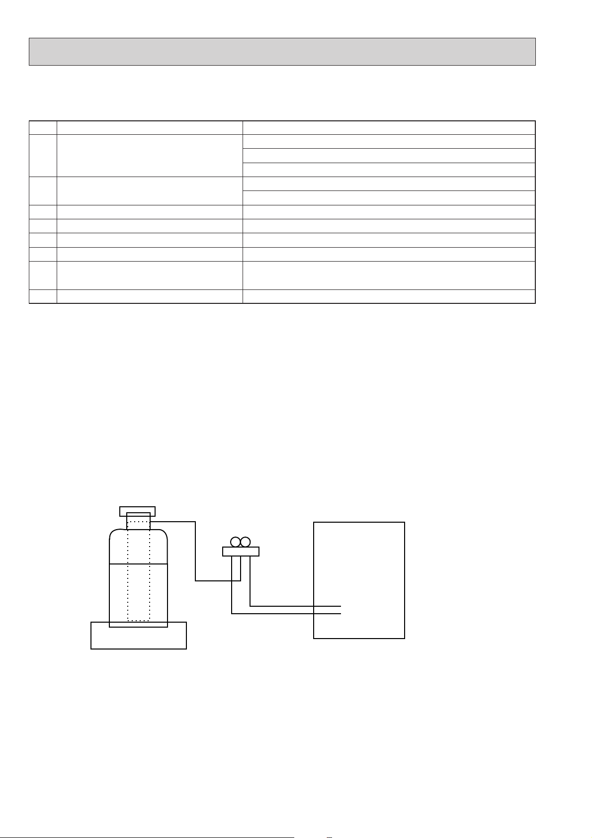
Gravimeter
Unit
[1] Service tools
Use the below service tools as exclusive tools for R407C refrigerant.
No. Tool name Specifications
1 Gauge manifold ·Only for R407C.
·Use the existing fitting SPECIFICATIONS. (UNF7/16)
·Use high-tension side pressure of 3.43MPa·G or over.
2 Charge hose ·Only for R407C.
·Use pressure performance of 5.10MPa·G or over.
3 Electronic scale
4 Gas leak detector ·Use the detector for R407C.
5 Adapter for reverse flow check. ·Attach on vacuum pump.
6 Refrigerant charge base.
7 Refrigerant cylinder. ·For R407C ·Top of cylinder (Brown)
·Cylinder with syphon
8 Refrigerant recovery equipment.
[2] Notice on repair service
·After recovering the all refrigerant in the unit, proceed to working.
·Do not release refrigerant in the air.
·After completing the repair service, recharge the cycle with the specified amount of
liquid refrigerant.
[3] Refrigerant recharging
(1) Refrigerant recharging process
1Direct charging from the cylinder.
·R407C cylinder are available on the market has a syphon pipe.
·Leave the syphon pipe cylinder standing and recharge it.
(By liquid refrigerant)
(2) Recharge in refrigerant leakage case
·After recovering the all refrigerant in the unit, proceed to working.
·Do not release the refrigerant in the air.
·After completing the repair service, recharge the cycle with the specified amount of
liquid refrigerant.
4

2 COMBINATION OF INDOOR AND OUTDOOR UNITS
Air intake
Air outlet
(Expels warm air during cooling)
Air intake
Air outlet
Air intake
Air outlet
Air intake
Air outlet
Heat pump type
Outdoor unit
PUH-P
Cooling only type
PU-P
PLH-P
·KAH
PCH-P·GAH
PKH-P·GALH
PKH-P·FALH
PSH-P·GAH
PLA-P·KA
PCA-P·GA
PKA-P·GAL
PKA-P·FAL
PSA-P·GA
OC181
OC182
OC176
OC175
OC212
OC181
OC182
OC176
OC175
OC212
YGA
—
—
—
—
—
—
—
YGA
—
—
—
—
—
—
—
YGA
—
—
—
—
—
—
YGA
—
—
—
—
—
—
VGA
—
—
—
—
—
—
VGA(1)
—
—
—
—
—
—
—
VGA
—
—
—
—
—
—
—
VGA
—
—
—
—
—
—
—
—
YGA
—
—
—
—
YGA
—
—
—
—
YGA
—
—
YGA
—
—
VGA
—
—
VGA(1)
—
—
—
—
YGA(1)
—
—
—
—
YGA
—
—
—
—
VGA
—
—
—
—
VGA
—
—
—
—
—
—
YGA
—
—
—
—
—
—
Indoor unit
1.6Service
Manual No.
Service Ref.
2 2.5 3 4 5 6 1.6 2 2.5 3 4 5 6
Heat pump with
electric heater
Heat pump without
electric heater or
Cooling only
REVISED
EDITION-A
REVISED
EDITION-A
REVISED
EDITION-A
REVISED
EDITION-A
REVISED
EDITION-A
REVISED
EDITION-A
REVISED
EDITION-A
REVISED
EDITION-A
3 PART NAMES AND FUNCTIONS
CHARGELESS SYSTEM
PRE-CHARGED REFRIGERANT IS SUPPLIED FOR PIPING LENGTH AT SHIPMENT.(Max.30m)
PU(H)-P1.6VGA
PUH-P1.6YGA
PU(H)-P2VGA, PUH-P2YGA
PU(H)-P2.5VGA
(1), PUH-P2.5YGA(1)
PU(H)-P3VGA, PU(H)-P3YGA
The refrigerant circuit with LEV(Linear Expansion Valve) and a large accumulator always control the optimal refrigerant
level regardless of the length (30m max. and 5m min.) of piping. The additional refrigerant charging work during
installation often causes problems. Heretofore it is completely eliminated. This unique system improves the quality
and reliability of the work done.It also helps to speed up the installation time.
PU(H)-P4YGA
5
PU(H)-P5YGA
PU(H)-P6YGA
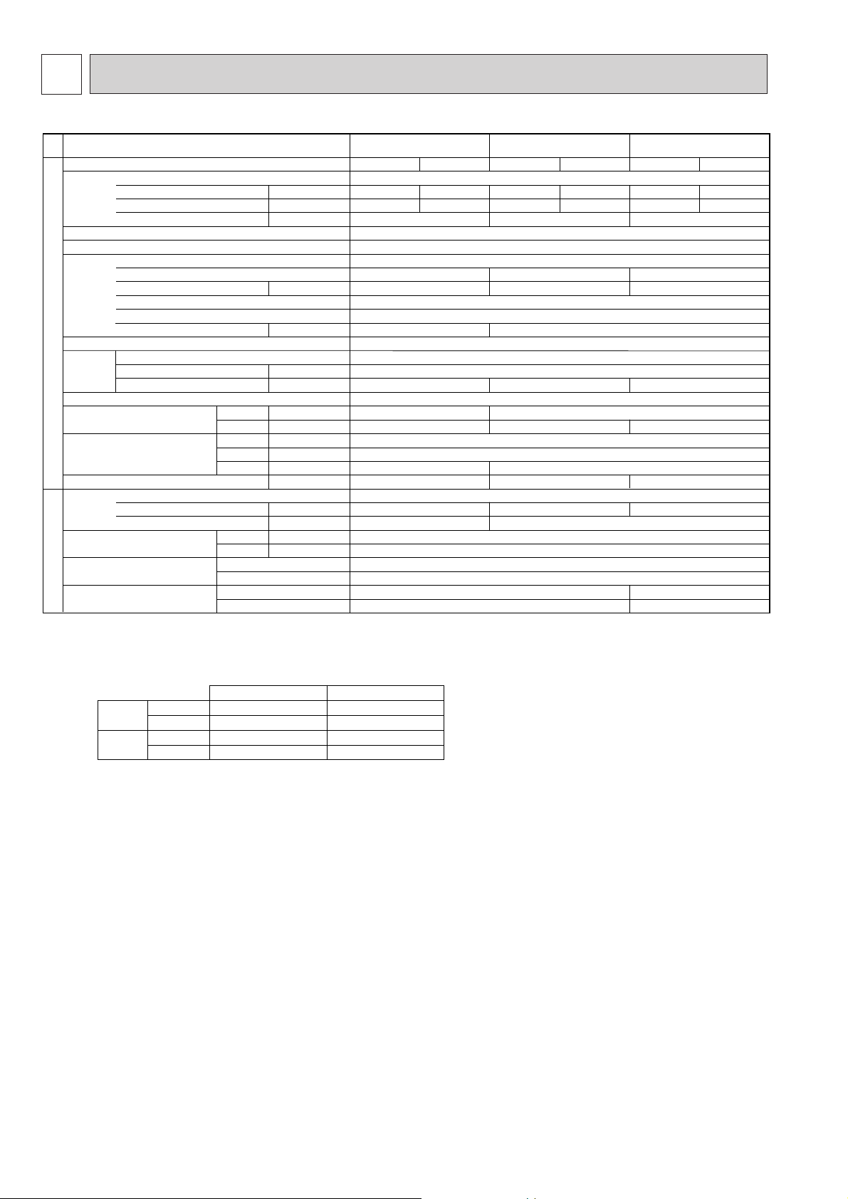
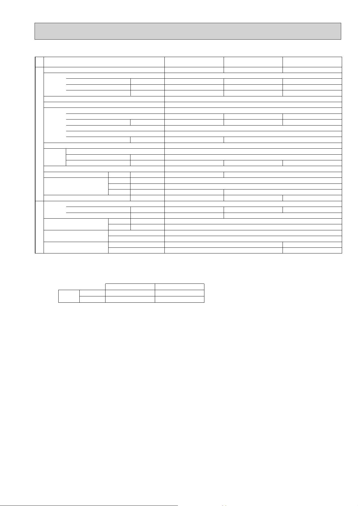
4 SPECIFICATIONS
kW
A
A
kW
W
kW
K
/min(CFM
)
dB
dB
mm(in.)
mm(in.)
mm(in.)
kg(lbs)
kg(lbs)
L
mm(in.)
mm(in.)
Function
Power supply (phase, cycle, voltage)
Input
Running current
Starting current
External finish
Refrigerant control
Compressor
Model
Motor output
Starter type
Protection devices
Crankcase heater
Heat exchanger
Fan Fan(drive) o No.
Fan motor output
Airflow
Defrost method
Noise level
Dimensions
Weight
Refrigerant
Charge
Oil (Model)
Pipe size O.D.
Connection method
Between the indoor &
outdoor unit
OUTDOOR UNIT
REFRIGERANT PIPING
Cooling
Heating
W
D
H
Liquid
Gas
Indoor side
Outdoor side
Height difference
Piping length
Notes1.Rating Conditions (ISO T1)
Cooling :Indoor : D.B. 27˚C(80˚F), W.B.19˚C (66˚F) Outdoor : D.B. 35˚C(95˚F), W.B. 24˚C (75˚F)
Heating :Indoor : D.B. 20˚C(68˚F) Outdoor : D.B. 7˚C(45˚F), W.B. 6˚C (43˚F)
Refrigerant piping length (one way) : 5m (16ft)
3. Above data based on indicated voltage
Indoor Unit 1 phase 240V 50Hz
Outdoor Unit 1 phase 240V 50Hz / 3 phase 415V 50Hz
2. Guaranteed operating range
Upper limit
Lower limit
Upper limit
Lower limit
Indoor
D.B. 35˚C, W.B. 22.5˚C
D.B. 19˚C, W.B. 15˚C
D.B. 28˚C
D.B. 17˚C
Outdoor
D.B. 46˚C
D.B. -5˚C
D.B. 24˚C, W.B. 18˚C
D.B. -11˚C, W.B. -12˚C
Cooling
Heating
Service Ref.
PUH-P1.6VGA / YGA PUH-P2VGA / YGA PUH-P2.5VGA
(1) / YGA(1)
Cooling
1.71
7.66 / 2.67
36 / 20
RE277VHSM / RE277YFKM
1.3
30
45(1,590)
46
48
650(25-5/8)
55(121)
2.6(5.7)
0.57 (Ester)MEL56
Single, 50Hz, 220-240V/3-ph, 50Hz, 380-415V(4wires)
74 / 30
Munsell 5Y 8/1
Linear Expansion Valve
Hermetic
NE38VMJM / NE38YEJM
1.7
Line start
Inner thermostat, HP switch, Discharge thermo. / Thermal relay, Discharge thermo, HP switch, Anti-phase protector.
Plate fin coil
Propeller (direct) o 1
0.07
55(1,940)
Reverse cycle
49
900(35-7/16)
330+20(13+3/4)
71(157)
R407C
3.1(6.8)
9.52(3/8)
15.88(5/8)
Flared
Flared
Heating
1.83
8.19 / 2.86
Cooling
2.63
11.78 / 4.11
38
48
855(33-5/8)
1.2 (Ester)MEL56
77 / 32
NE41VMJM / NE41YEJM
1.9
50(1,770)
50
82(181)
3.3(7.3)
Max. 50m
Max. 50m
Heating
2.58
11.55 / 4.03
Cooling
2.48
11.11 / 3.88
Heating
2.57
11.51 / 4.02
Max. 40m
Max. 40m
1.Heat pump
6

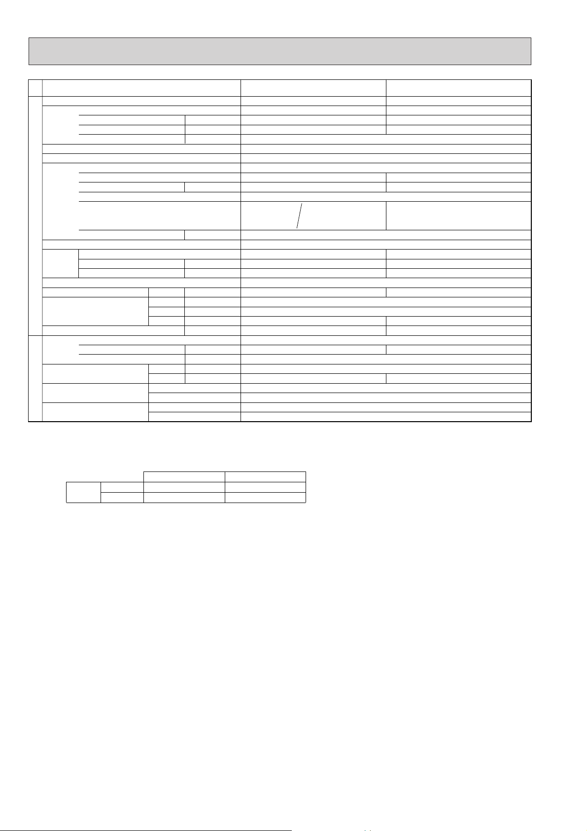
Service Ref.
Function
Power supply (phase, cycle, voltage)
External finish
Refrigerant control
Compressor
Heat exchanger
OUTDOOR UNIT
Fan Fan(drive) o No.
Defrost method
Noise level
Dimensions
Weight
Refrigerant
Pipe size O.D.
Connection method
Between the indoor &
REFRIGERANT PIPING
outdoor unit
Notes1.Rating Conditions (ISO T1)
2. Guaranteed operating range
3. Above data based on indicated voltage
Input
Running current
Starting current
Model
Motor output
Starter type
Protection devices
Crankcase heater
Fan motor output
Airflow
Cooling
Heating
W
D
H
Charge
Oil (Model)
Cooling :Indoor : D.B. 27˚C(80˚F), W.B. 19˚C(66˚F) Outdoor : D.B. 35˚C(95˚F), W.B. 24˚C(75˚F)
Heating :Indoor : D.B. 20˚C(68˚F) Outdoor : D.B. 7˚C(45˚F), W.B. 6˚C(43˚F)
Refrigerant piping length (one way) : 5m (16ft)
Cooling
Heating
Upper limit
Lower limit
Upper limit
Lower limit
Indoor Unit 1 phase 240V 50Hz
Outdoor Unit 1 phase 240V 50Hz / 3 phase 415V 50Hz
Liquid
Gas
Indoor side
Outdoor side
Height difference
Piping length
Indoor
D.B. 35˚C, W.B. 22.5˚C
D.B. 19˚C, W.B. 15˚C
D.B. 28˚C
D.B. 17˚C
kW
kW
kW
K
/min(CFM
mm(in.)
mm(in.)
mm(in.)
kg(lbs)
kg(lbs)
mm(in.)
mm(in.)
A
A
W
dB
dB
L
Single, 50Hz, 220-240V/3-ph, 50Hz, 380-415V(4wires)
Internal thermostat
Discharge thermo
)
D.B. 46˚C
D.B. -5˚C
D.B. 24˚C, W.B. 18˚C
D.B. -11˚C, W.B. -12˚C
PUH-P3VGA / YGA PUH-P4YGA
Cooling
3.34
14.64 / 5.46
NE52VNJM / NE52YDJM
HP switch
Outdoor
93 / 41
Thermal relay
Discharge thermo, HP switch
Anti-phase protector
Propeller (direct) o 1
0.07
50(1,770)
855(33-5/8)
82(181)
3.7(8.2)
15.88(5/8)
Heating
3.52
15.43 / 5.76
2.5
49
51
Cooling
3-ph, 50Hz, 380-415V(4wires)
3.36
5.49
Munsell 5Y 8/1
Linear Expansion Valve
Hermetic
Line start
Anti-phase protector, Thermal relay
Discharge thermo, HP switch
38
Plate fin coil
Reverse cycle
900(35-7/16)
330+20(13+3/4)
R407C
1.6 (Ester)MEL56
9.52(3/8)
Flared
Flared
Max. 50m
Max. 50m
Heating
3.54
5.79
45
NE56YDJM
2.7
Propeller (direct) o 2
0.07+0.07
85(3,000)
51
53
1,260(49-5/8)
96(212)
4.0(8.8)
19.05(3/4)
7
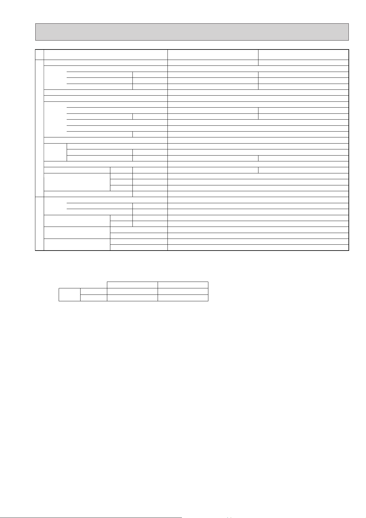
Service Ref.
Function
Power supply (phase, cycle, voltage)
External finish
Refrigerant control
Compressor
Heat exchanger
Fan Fan(drive) o No.
OUTDOOR UNIT
Defrost method
Noise level
Dimensions
Weight
Refrigerant
Pipe size O.D.
Connection method
Between the indoor &
REFRIGERANT PIPING
outdoor unit
Notes1.Rating Conditions (ISO T1)
2. Guaranteed operating range
3. Above data based on indicated voltage
Input
Running current
Starting current
Model
Motor output
Starter type
Protection devices
Crankcase heater
Fan motor output
Airflow
Cooling
Heating
W
D
H
Charge
Oil (Model)
Cooling :Indoor : D.B. 27˚C(80˚F), W.B. 19˚C (66˚F) Outdoor : D.B. 35˚C(95˚F), W.B. 24˚C (75˚F)
Heating :Indoor : D.B. 20˚C(68˚F) Outdoor : D.B. 7˚C(45˚F), W.B. 6˚C (43˚F)
Refrigerant piping length (one way) : 5m (16ft)
Cooling
Heating
Upper limit
Lower limit
Upper limit
Lower limit
Indoor Unit 1 phase 240V 50Hz
Outdoor Unit 3 phase 415V 50Hz
Liquid
Gas
Indoor side
Outdoor side
Height difference
Piping length
Indoor
D.B. 35˚C, W.B. 22.5˚C
D.B. 19˚C, W.B. 15˚C
D.B. 28˚C
D.B. 17˚C
K
/min(CFM
dB(A)
dB(A)
mm(in.)
mm(in.)
mm(in.)
kg(lbs)
kg(lbs)
mm(in.)
mm(in.)
kW
A
A
kW
Internal thermostat, Anti-phase protector, thermal relay, HP switch, Discharge thermo, LP switch
W
kW
)
L
Outdoor
D.B. 46˚C
D.B. -5˚C
D.B. 24˚C, W.B. 18˚C
D.B. -11˚C, W.B. -12˚C
PUH-P5YGA PUH-P6YGA
Cooling
5.25
8.39
HE86YAA
95(3,360)
Heating
3-ph, 50Hz, 380-415V(4wires)
5.47
8.74
79
Linear Expansion Valve
4.3
53
55
Cooling
10.17
Munsell 5Y 8/1
Hermetic
Line start
38
Plate fin coil
Propeller (direct) o 2
0.075+0.075
Reverse cycle
1,050(41-5/16)
330+20(13+3/4)
1,260(49-5/8)
122(269)
R407C
5.8(12.8)
2.0 (Ester)MEL32
9.52(3/8)
19.05(3/4)
Flared
Flared
Max. 50m
Max. 50m
6.36
Heating
6.43
10.28
84
HE101YAA
5.1
100(3,530)
55
57
8
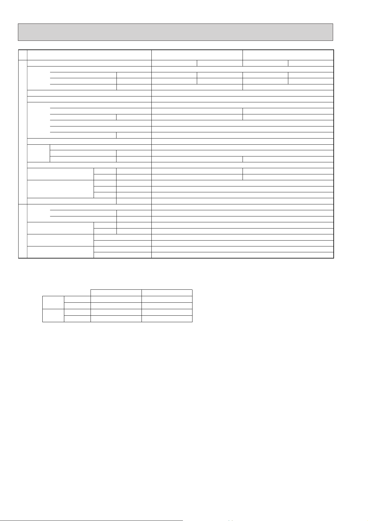
2. Cooling only type
Service Ref.
Function
Power supply (phase, cycle, voltage)
External finish
Refrigerant control
Compressor
OUTDOOR UNIT
Heat exchanger
Fan Fan(drive) o No.
Defrost method
Noise level
Dimensions
Weight
Refrigerant
Pipe size O.D.
Connection method
Between the indoor &
REFRIGERANT PIPING
outdoor unit
Notes1.Rating Conditions (ISO T1)
Input
Running current
Starting current
Model
Motor output
Starter type
Protection devices
Crankcase heater
Fan motor output
Airflow
Cooling
W
D
H
Charge
Oil (Model)
Liquid
Gas
Indoor side
Outdoor side
Height difference
Piping length
Cooling :Indoor : 27˚C(80˚F)DB. 19˚C (66˚F)WB Outdoor : 35˚C(95˚F)DB. 24˚C (75˚F)WB
Refrigerant piping length (one way) : 5m (16ft)
kW
kW
kW
K
/min(CFM
mm(in.)
mm(in.)
mm(in.)
kg(lbs)
kg(lbs)
mm(in.)
mm(in.)
A
A
W
)
dB
L
PU-P1.6VGA PU-P2VGA PU-P2.5VGA
Cooling
1.71
7.66
36
RE277VHSM
1.3
Inner thermostat, HP switch, Discharge thermo
30
45(1,590)
46
650(25-5/8)
55(121)
2.6(5.7)
0.57 (Ester)MEL56
Max. 40m
Max. 40m
Cooling
Single, 50Hz, 220-240V
2.48
11.11
74
Munsell 5Y 8/1
Linear Expansion Valve
Hermetic
NE38VMJM
1.7
Line start
Plate fin coil
Propeller (direct) o 1
0.07
55(1,940)
—
900(35-7/16)
330+20(13+3/4)
855(33-5/8)
71(157)
R407C
3.1(6.8)
1.2 (Ester)MEL56
9.52(3/8)
15.88(5/8)
Flared
Flared
(1)
Cooling
2.63
11.78
77
NE41VMJM
1.9
38
50(1,770)
48
82(181)
3.3(7.3)
Max. 50m
Max. 50m
2. Guaranteed operating range
Indoor
Cooling
3. Above data based on indicated voltage
Upper limit
Lower limit
Indoor Unit 1 phase 240V 50Hz
Outdoor Unit 1 phase 240V 50Hz
D.B. 35˚C, W.B. 22.5˚C
D.B. 19˚C, W.B. 15˚C
Outdoor
D.B.
46˚C
D.B.
-5˚C
9
Service Ref.
Function
Power supply (phase, cycle, voltage)
External finish
Refrigerant control
Compressor
OUTDOOR UNIT
Heat exchanger
Fan Fan(drive) o No.
Defrost method
Noise level
Dimensions
Weight
Refrigerant
Pipe size O.D.
Connection method
Between the indoor &
REFRIGERANT PIPING
outdoor unit
Notes1.Rating Conditions (ISO T1)
Input
Running current
Starting current
Model
Motor output
Starter type
Protection devices
Crankcase heater
Fan motor output
Airflow
Cooling
W
D
H
Charge
Oil (Model)
Liquid
Gas
Indoor side
Outdoor side
Height difference
Piping length
Cooling :Indoor : D.B. 27˚C(80˚F), W.B. 19˚C(66˚F) Outdoor : D.B. 35˚C(95˚F), W.B. 24˚C(75˚F)
Refrigerant piping length (one way) : 5m (16ft)
kW
kW
kW
K
/min(CFM
mm(in.)
mm(in.)
mm(in.)
kg(lbs)
kg(lbs)
mm(in.)
mm(in.)
A
A
W
dB
L
Single, 50Hz, 220-240V/3-ph, 50Hz, 380-415V(4wires)
Internal thermostat
Discharge thermo
)
PU-P3VGA / YGA PU-P4YGA
Cooling
3.34
14.64/5.46
93/41
NE52VNJM / NE52YDJM
HP switch
Propeller (direct) o 1
2.5
Thermal relay
Discharge thermo, HP switch
Anti-phase protector
0.07
50(1,770)
49
855(33-5/8)
82(181)
3.7(8.2)
15.88(5/8)
3-ph, 50Hz, 380-415V(4wires)
Cooling
3.36
5.49
45
Munsell 5Y 8/1
Linear Expansion Valve
Hermetic
NE56YDJM
2.7
Line start
Anti-phase protector, thermal relay
Discharge thermo, HP switch
38
Plate fin coil
Propeller (direct) o 2
0.07+0.07
85(3,000)
—
51
900(35-7/16)
330+20(13+3/4)
1,260(49-5/8)
96(212)
R407C
4.0(8.8)
1.6 (Ester)MEL56
9.52(3/8)
19.05(3/4)
Flared
Flared
Max. 50m
Max. 50m
2. Guaranteed operating range
Indoor
Cooling
3. Above data based on indicated voltage
Upper limit
Lower limit
Indoor Unit 1 phase 240V 50Hz
Outdoor Unit 1 phase 240V 50Hz/3 phase 415V 50Hz
D.B. 35˚C , W.B. 22.5˚C
D.B. 19˚C, W.B. 15˚C
Outdoor
D.B. 46˚C
D.B. -5˚C
10
Service Ref.
Function
Power supply (phase, cycle, voltage)
External finish
Refrigerant control
Compressor
OUTDOOR UNIT
Heat exchanger
Fan Fan(drive) o No.
Defrost method
Noise level
Dimensions
Weight
Refrigerant
Pipe size O.D.
Connection method
Between the indoor &
REFRIGERANT PIPING
outdoor unit
Notes1.Rating Conditions (ISO T1)
Input
Running current
Starting current
Model
Motor output
Starter type
Protection devices
Crankcase heater
Fan motor output
Airflow
Cooling
W
D
H
Charge
Oil (Model)
Liquid
Gas
Indoor side
Outdoor side
Height difference
Piping length
Cooling :Indoor : D.B. 27˚C(80˚F), W.B. 19˚C(66˚F) Outdoor : D.B. 35˚C(95˚F), W.B. 24˚C(75˚F)
Refrigerant piping length (one way) : 5m (16ft)
kW
kW
kW
K
/min(CFM
dB
mm(in.)
mm(in.)
mm(in.)
kg(lbs)
kg(lbs)
mm(in.)
mm(in.)
A
A
Internal thermostat, Anti-phase protector, thermal relay, HP switch, Discharge thermo, LP switch
W
)
L
PU-P5YGA PU-P6YGA
Cooling
3-ph, 50Hz, 380-415V(4wires)
5.25
8.39
79
HE86YAA
4.3
95(3,360)
53
Cooling
6.36
10.17
84
Munsell 5Y 8/1
Linear Expansion Valve
Hermetic
HE101YAA
5.1
Line start
38
Plate fin coil
Propeller (direct) o 2
0.075+0.075
100(3,530)
—
55
1,050(41-5/16)
330+20(13+3/4)
1,260(49-5/8)
122(269)
R407C
5.8(12.8)
2.0(Ester)MEL32
9.52(3/8)
19.05(3/4)
Flared
Flared
Max. 50m
Max. 50m
2. Guaranteed operating range
Indoor
Cooling
3. Above data based on indicated voltage
Upper limit
Lower limit
Indoor Unit 1 phase 240V 50Hz
Outdoor Unit 3 phase 415V 50Hz
D.B. 35˚C , W.B.22.5˚C
D.B. 19˚C, W.B. 15˚C
Outdoor
D.B.
46˚C
D.B.
-5˚C
11
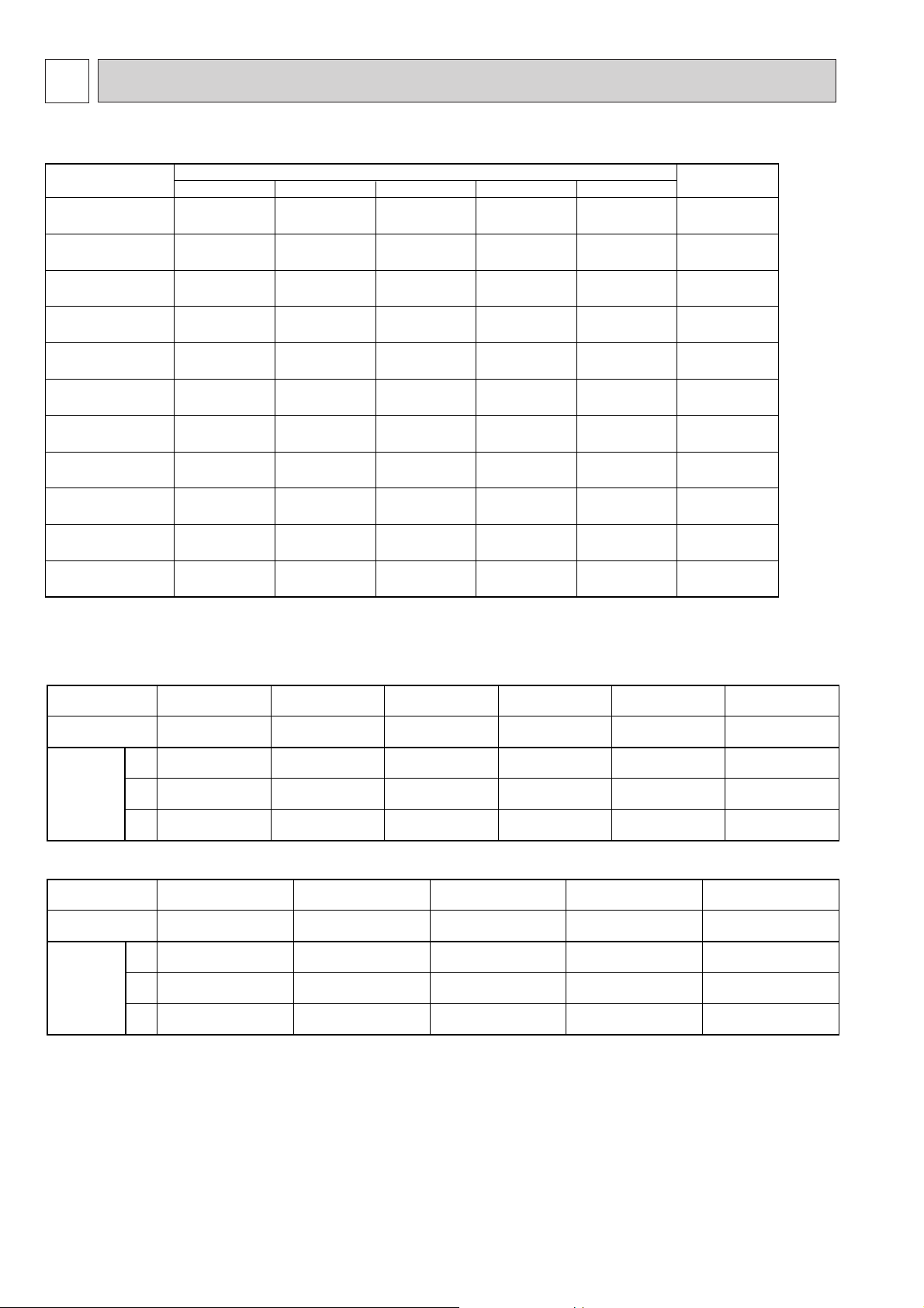
5 DATA
PUH-P1.6VGA
PU-P1.6VGA
PUH-P1.6YGA
PUH-P2VGA
PU-P2VGA
PUH-P2YGA
PUH-P2.5VGA(1)
PU-P2.5VGA(1)
PUH-P2.5YGA(1)
PUH-P3VGA
PU-P3VGA
PUH-P3YGA
PU-P3YGA
PUH-P4YGA
PU-P4YGA
PUH-P5YGA
PU-P5YGA
PUH-P6YGA
PU-P6YGA
Piping length (one way)
10m 20m 30m
40m
50m
Factory
charged
2.4
2.4
2.5
2.5
2.7
2.7
2.9
2.9
3.4
5.1
5.1
2.5
2.5
2.6
2.6
2.8
2.8
3.1
3.1
3.7
5.4
5.4
2.6
2.6
3.1
3.1
3.3
3.3
3.7
3.7
4.0
5.8
5.8
3.0
3.0
3.7
3.7
3.9
3.9
4.3
4.3
4.7
6.5
6.5
—
—
—
—
4.5
4.5
4.9
4.9
5.4
7.2
7.2
2.6
2.6
3.1
3.1
3.3
3.3
3.7
3.7
4.0
5.8
5.8
Service Ref.
Compressor model
Winding
Resistance
( " )
U-V
(R-C)
U-W
(S-C)
W-V
U-V
(R-C)
U-W
(S-C)
W-V
RE277VHSM RE277YFKM
Unit
PUH-P1.6VGA
PU-P1.6VGA
PUH-P1.6YGA
PUH-P2VGA
PU-P2VGA
PUH-P2.5VGA
(1)
PU-P2.5VGA(1)
NE38VMJM NE41VMJM
1.80
3.00
—
10.8
10.8
10.8
5.21
5.21
5.21
NE38YEJM
PUH-P2YGA
5.00
5.00
5.00
NE41YEJM
PUH-P2.5YGA
(1)
0.85
2.15
—
0.79
2.19
—
Unit
Compressor model
Winding
Resistance
( " )
PUH-P5YGA
PU-P5YGA
PUH-P6YGA
PU-P6YGA
HE86YAA HE101YAA
2.40
2.40
2.40
PUH-P4YGA
PU-P4YGA
NE56YDJM
3.20
3.20
3.20
PUH-P3VGA
PU-P3VGA
NE52VNJM
0.64
1.67
—
PUH-P3YGA
PU-P3YGA
NE52YDJM
3.70
3.70
3.70
2.20
2.20
2.20
1. REFILLING REFRIGERANT CHARGE (R407C : kg)
2. COMPRESSOR TECHNICAL DATA
at 20˚C
at 20˚C
12
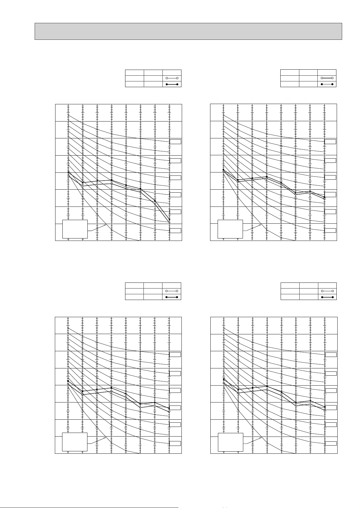
3. NOISE CRITERION CURVES
90
80
70
60
50
40
30
20
10
63 125 250 500 1000 2000 4000 8000
APPROTIMATE
TERESHOLD OF
REARING FOR
CONTINUOUS
NOISE
NC-60
NC-50
NC-40
NC-30
NC-20
NC-70
OCTAVE BAND SOUND PRESSURE LEVEL, dB re 0.002 MICRO BAR
BAND CENTER FREQUENCIES, Hz
COOLING
NOTCH
HEATING
SPL(dB) LINE
PUH-P2VGA / YGA
PU-P2VGA
48
49
90
80
70
60
50
40
30
20
10
OCTAVE BAND SOUND PRESSURE LEVEL, dB re 0.002 MICRO BAR
63 125 250 500 1000 2000 4000 8000
BAND CENTER FREQUENCIES, Hz
APPROTIMATE
TERESHOLD OF
REARING FOR
CONTINUOUS
NOISE
NC-60
NC-50
NC-40
NC-30
NC-20
NC-70
COOLING
NOTCH
HEATING
SPL(dB) LINE
PUH-P2.5VGA(1) / YGA(1)
PU-P2.5VGA(1)
48
50
90
80
70
60
50
40
30
20
10
63 125 250 500 1000 2000 4000 8000
APPROTIMATE
TERESHOLD OF
REARING FOR
CONTINUOUS
NOISE
NC-60
NC-50
NC-40
NC-30
NC-20
NC-70
OCTAVE BAND SOUND PRESSURE LEVEL, dB re 0.002 MICRO BAR
BAND CENTER FREQUENCIES, Hz
COOLING
NOTCH
HEATING
SPL(dB) LINE
49
51
PUH-P3VGA / YGA
PU-P3VGA / YGA
PUH-P1.6VGA / YGA
PU-P1.6VGA
90
80
NOTCH
COOLING
HEATING
SPL(dB)48LINE
46
70
60
50
40
30
APPROTIMATE
20
TERESHOLD OF
OCTAVE BAND SOUND PRESSURE LEVEL, dB re 0.002 MICRO BAR
REARING FOR
CONTINUOUS
NOISE
10
63 125 250 500 1000 2000 4000 8000
BAND CENTER FREQUENCIES, Hz
NC-70
NC-60
NC-50
NC-40
NC-30
NC-20
13
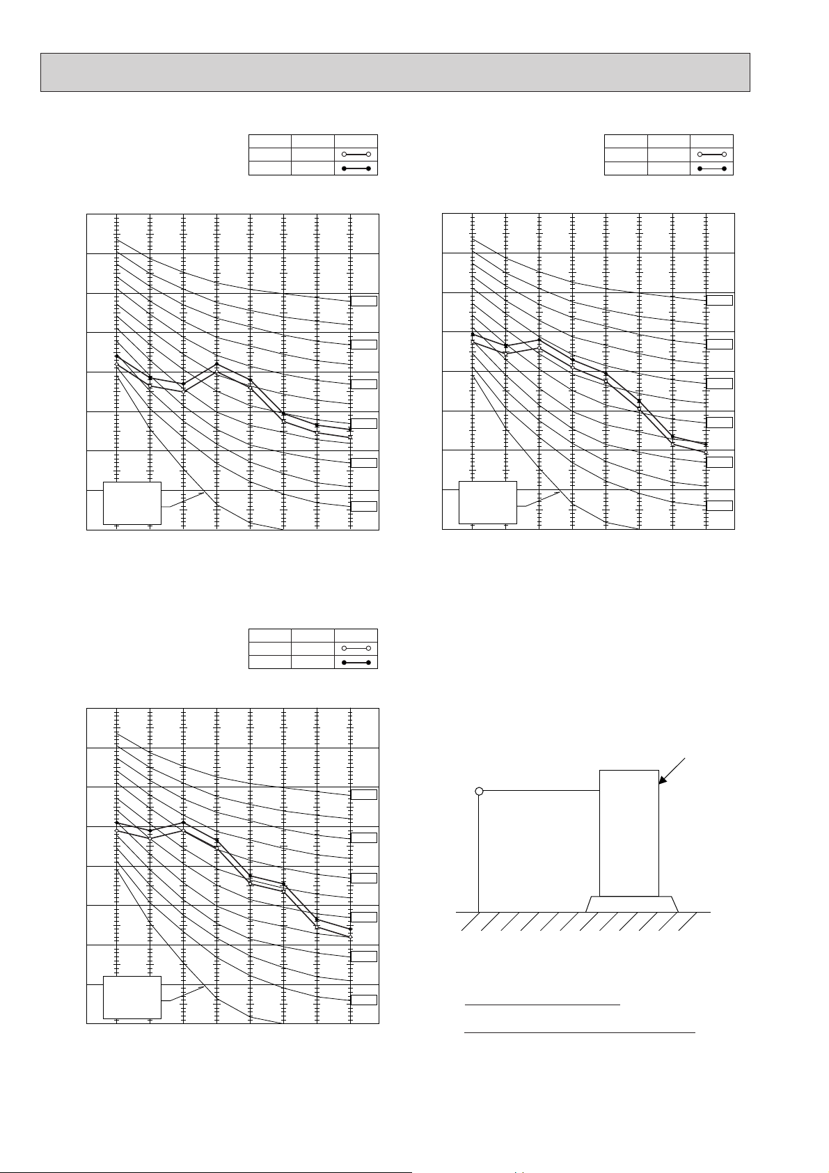
PUH-P4YGA
PU-P4YGA
NOTCH
COOLING
HEATING
SPL(dB) LINE
51
53
PUH-P5YGA
PU-P5YGA
NOTCH
COOLING
HEATING
SPL(dB) LINE
53
55
90
80
70
60
50
40
30
APPROTIMATE
20
TERESHOLD OF
OCTAVE BAND SOUND PRESSURE LEVEL, dB re 0.002 MICRO BAR
REARING FOR
CONTINUOUS
NOISE
10
63 125 250 500 1000 2000 4000 8000
BAND CENTER FREQUENCIES, Hz
NC-70
NC-60
NC-50
NC-40
NC-30
NC-20
90
80
70
60
50
40
30
APPROTIMATE
20
OCTAVE BAND SOUND PRESSURE LEVEL, dB re 0.002 MICRO BAR
TERESHOLD OF
REARING FOR
CONTINUOUS
NOISE
10
63 125 250 500 1000 2000 4000 8000
BAND CENTER FREQUENCIES, Hz
NC-70
NC-60
NC-50
NC-40
NC-30
NC-20
PUH-P6YGA
PU-P6YGA
90
80
70
60
50
40
30
APPROTIMATE
20
OCTAVE BAND SOUND PRESSURE LEVEL, dB re 0.002 MICRO BAR
TERESHOLD OF
REARING FOR
CONTINUOUS
NOISE
10
63 125 250 500 1000 2000 4000 8000
BAND CENTER FREQUENCIES, Hz
NOTCH
COOLING
HEATING
SPL(dB) LINE
55
57
NC-70
NC-60
NC-50
NC-40
NC-30
NC-20
UNIT
MICROPHONE
1m
1m
GROUND
Ambient temperature 27:
Test conditions are based on JIS Z8731
14
 Loading...