


Mitsubishi PLH-3AK.UK, PLH-3AKH.UK, PLH-4AKS.UK, PLH-4AKHS.UK, PLH-5AKS.UK Service Manual
...SPLIT-TYPE, HEAT PUM PAIR CONDITIONERS
No. OC211
REVISED EDITION-A
TECHNICAL & SERVICE MANUAL
Series PLH
Indoor unit [Model names]
PLH-3AK
PLH-3AKH
PLH-4AKS
PLH-4AKHS
PLH-5AKS
PLH-5AKHS
PLH-6AKS
PLH-6AKHS
Model name indication
FILTER

 CHECK MODE
TEST RUN
Ceiling Cassettes
[Service Ref.]
PLH-3AK.UK PLH-3AK1.UK PLH-3AKH.UK PLH-3AKH1.UK PLH-4AKS.UK PLH-4AKS1.UK PLH-4AKHS.UK PLH-4AKHS1.UK PLH-5AKS.UK PLH-5AKS1.UK PLH-5AKHS.UK PLH-5AKHS1.UK PLH-6AKS.UK PLH-6AKS1.UK PLH-6AKHS.UK PLH-6AKHS1.UK
Revision:
•PLH-3AK1.UK, PLH-3AKH1.UK, PLH-4AKS1.UK, PLH-4AKHS1.UK, PLH-5AKS1.UK, PLH-5AKHS1.UK, PLH-6AKS1.UK and PLH-6AKHS1.UK are added in REVISED EDITION-A.
•“14. PARTS LIST” has been modified.
Note:
•This manual does not cover the following outdoor units. When servicing them, please refer to the following service manual and this manual in a set.
[Service Ref.]
(OC150 REVISED EDITION-A) PUH-3VKA2.UK PUH-3YKA2.UK PUH-4YKSA2.UK PUH-5YKSA2.UK PUH-6YKSA2.UK
(OC184) PUH-4VKSA.UK
• Please void OC211.
CONTENTS
1. TECHNICAL CHANGES··········
2. PART NAMES AND FUNCTIONS ······
3. SPECIFICATIONS·············
4. DATA ··················
5. OUTLINES AND DIMENSIONS·······
6. WIRING DIAGRAM············
7. REFRIGERANT SYSTEM DIAGRAM ······
8. OPERATION FLOW-CHART ········
INDOOR UNIT |
|
9. MICROPROCESSOR CONTROL······ |
|
|
|
|
|
10. TROUBLESHOOTING ··········· |
|
|
11. 4-WAY AIR FLOW SYSTEM ········ |
CHECK TESTRUN |
|
12. SYSTEM CONTROL ············ |
MODEL SELECT |
˚C |
|
|
AMPM |
|
|
AMPM |
|
ON/OFF |
TEMP |
13. DISASSEMBLY PROCEDURE ······· |
ON/OFF |
|
|
|
|
14. PARTS LIST··············· |
|
|
15. OPTIONAL PARTS ············ |
PLH- •AK.UK |
PLH- •AK1.UK |
PLH- •AKH.UK |
PLH- •AKH1.UK |
PLH- •AKS.UK |
PLH- •AKS1.UK |
PLH- •AKHS.UK |
PLH- •AKHS1.UK |
WIRED REMOTE |
WIRELESS REMOTE |
CONTROLLER |
CONTROLLER |
Revision:
1. “ 14. PARTS LIST ” has been modified on page 83 and 84.
Page |
Revise point |
Service Ref. |
Incorrect |
Correct |
|
|
|
|
|
|
|
|
FUNCTIONAL PARTS |
PLH-5AKS.UK |
|
|
|
84 |
No.16 |
PLH-5AKHS.UK |
S70 17J 202 |
S70 E00 202 |
|
ROOM |
|||||
PLH-6AKS.UK |
|||||
|
TEMPERATURE |
|
|
||
|
PLH-6AKHS.UK |
|
|
||
|
THERMISTOR |
|
|
||
|
|
|
|
||
Spare CONTROLLER BOARD are unified. |
|
|
|||
|
|
|
|
|
|
Page |
Revise point |
Service Ref. |
Old |
New |
|
parts code |
part code |
||||
|
|
|
|||
|
|
|
|
|
|
|
|
PLH-3AK.UK |
S70 E01 310 |
|
|
|
|
|
|
|
|
83 |
FUNCTIONAL PARTS |
PLH-3AKH.UK |
S70 E02 310 |
|
|
No.4 CONTROLLER |
|
|
|
||
PLH-4AKS.UK |
S70 E03 310 |
|
|||
|
|
||||
|
BOARD |
|
|||
|
|
|
|
||
|
PLH-4AKHS.UK |
S70 E04 310 |
S70 E01 310* |
||
|
|
||||
|
|
|
|
||
|
|
PLH-5AKS.UK |
S70 E05 310 |
||
|
|
|
|||
|
FUNCTIONAL PARTS |
|
|
|
|
|
PLH-5AKHS.UK |
S70 E06 310 |
|
||
84 |
No.4 CONTROLLER |
|
|
|
|
PLH-6AKS.UK |
S70 E07 310 |
|
|||
|
BOARD |
|
|||
|
|
PLH-6AKHS.UK |
S70 E08 310 |
|
|
|
|
|
|
|
|
DRAIN PUMP has been changed. |
|
|
|||
|
|
|
|
|
|
Page |
Revise point |
Service Ref. |
Old |
New |
|
part code |
part code |
||||
|
|
|
|||
|
|
|
|
|
|
|
FUNCTIONAL PARTS |
PLH-3AK.UK |
|
|
|
83 |
PLH-3AKH.UK |
|
|
||
No.7 DRAIN PUMP |
PLH-4AKS.UK |
|
|
||
|
|
|
|||
|
|
PLH-4AKHS.UK |
S70 E01 355 |
S70 E02 355 |
|
|
FUNCTIONAL PARTS |
PLH-5AKS.UK |
|||
|
|
|
|||
84 |
PLH-5AKHS.UK |
|
|
||
No.7 DRAIN PUMP |
PLH-6AKS.UK |
|
|
||
|
|
|
|||
|
|
PLH-6AKHS.UK |
|
|
|
2. The description “The part name of symbol “I.B” is “SPCB” ” is added on both pages of wiring diagram and part list.
1 
 TECHNICAL CHANGES
PLH-3AK.UK |
PLH-3AK1.UK |
PLH-3AKH.UK |
PLH-3AKH1.UK |
PLH-4AKS.UK |
PLH-4AKS1.UK |
PLH-4AKHS.UK |
PLH-4AKHS1.UK |
PLH-5AKS.UK |
PLH-5AKS1.UK |
PLH-5AKHS.UK |
PLH-5AKHS1.UK |
PLH-6AKS.UK |
PLH-6AKS1.UK |
PLH-6AKHS.UK |
PLH-6AKHS1.UK |

 ˚C
˚C
TEMP.
ON/OFF
WIRELESS REMOTE CONTROLLER has been changed. (PAR-SL95K-E PAR-SL97A-E)
2
2 
 PART NAMES AND FUNCTIONS
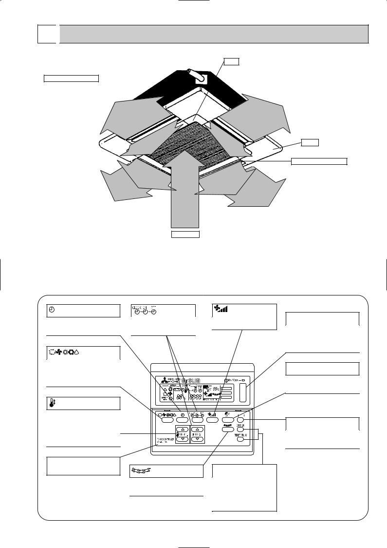
●Indoor Unit
Horizontal Air Outlet
Sets airflow of horizontal automatically during cooling or dehumidifying.
Filter
Removes dust and pollutants from intake air
Grille
Auto Air Swing Vane Disperses airflow up and down and adjusts the angle of airflow direction.
Air Intake
Intakes air from room.
● Remote controller
On the controls are set, the same operation mode can be repeated by simply pressing the ON/OFF button.
● Operation buttons
button
This switches between continuous operation and the timer operation.
button
Press this button to switch the cooling, electronic dry (dehumidify), automatic and heating modes.
TEMP. button
This sets the room temperature, The temperature setting can be performed in 1°C units
Setting range
Cooling 19°C to 30°C Heating 17°C to 28°C
This model name of the remote controller is indicated.
button |
button |
This sets the current time. start
This sets the ventilation fan
time and stop time.
speed.
FILTER
CHECK MODE
TEST RUN
button |
CHECK-TEST RUN button |
|
This switches the horizontal fan |
Only press this button to per- |
|
motion ON and OFF. |
||
form an inspection check or test |
||
|
||
(This button does not operate on this |
operation, Do not use it for nor- |
|
mal operation. |
||
model) |
||
|
ON/OFF button
This switches between the operation and stop modes each time it is pressed. The lamp on this button lights during operation.
 button
This adjusts the vertical angle of the ventilation.
FILTER button
This resets the filter cleaning indication display.
3
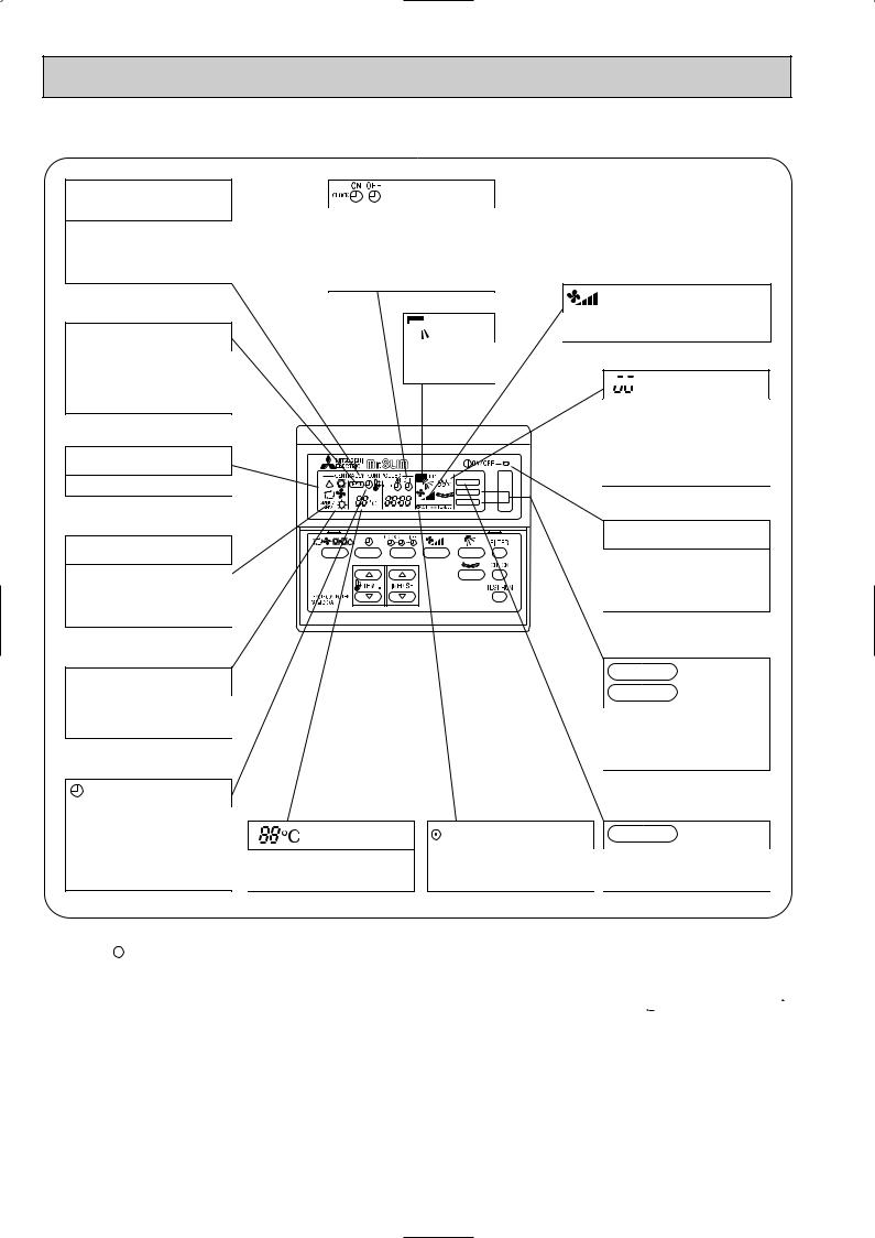
● Display
CENTRALLY CONTROLLED display
This indicates when the unit is controlled by optional features such as central control type remote controller.
CHECK display
This indicates when a malfunction has occurred in the unit which should be checked.
OPERATION MODE display
This indicates the operation mode.
STANDBY display
The [STANDBY] symbol is only displayed from the time the heating operation starts until the heated air begins to blow.
display
The current time , start time and stop time can be displayed in ten second intervals by pressing the time setting button. The start time or stop time is always displayed during the timer operation.
 display
This displays the air direction.
FILTER |
CHECK MODE
TEST RUN
In this display example on the bottom left, a condition where all display lamps light is shown for explanation purposes although this differs from actual operation.
display
The selected fan speed is displayed.


 display
The temperature of the suction air is displayed during operation. The display range is 10° to 35°C. The display flashes 10°C when the actual temperature is less than 10° and flashes 35°C when the actual temperature is greater than 35°C.
Operation lamp
This lamp lights during operation, goes off when the unit stops and flashes when a malfunction occurs.
DEFROST display
This indicates when the defrost operation is performed.
display
This indicates when the continuous operation and time operation modes are set.
It also display the time for the timer operation at the same time as when it is set.
display
This displays the selected setting temperature.
CHECK MODE
display
TEST RUN
This display lights in the check mode or when a test operation is performed.
display |
FILTER |
display |
This lamp lights when electricity is |
This lamp lights when the filter need |
|
supplied to the unit. |
to be cleaned. |
|
Caution
●Only the  display lights when the unit is stopped and power supplied to the unit.
●When power is turned ON for the first time the (CENTRAL CTRL) display appears to go off momentarily but this is not a malfunction.
●When the central control remote control unit, which is sold separately, is used the ON-OFF button, 


 button and
  TEMP. button do not operate.
●“NOT AVAILABLE” is displayed when the 


 button are pressed.This indicates that this room unit is not equipped with the fan direction adjustment function and the louver function.
4
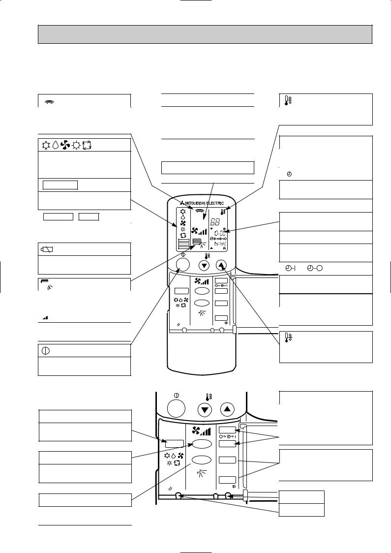
PLH-3AK.UK PLH-4AKS.UK PLH-5AKS.UK PLH-6AKS.UK PLH-3AKH.UK PLH-4AKHS.UK PLH-5AKHS.UK PLH-6AKHS.UK ● Wireless remote controller
● When cover is open.
display
Lights up while transmission to the indoor unit is mode using switches.
display
OPERATION MODE display
Operation mode display indicates which operation mode is in effect.
• FUNCTION display
Lights up when function are set.
• TEST RUN • CHECK display
CHECK&TEST RUN display indicates that the unit is being checked or test-run.
display
Displays when batteries are dead.
 display
The vertical direction of airflow is indicated.

 display
FAN SPEED display indicates which fan speed has been selected.
display
The unit is turned ON and OFF alternately each time the button is pressed.
● When cover is open.
MODE SELECT button
Used to switch the operation mode between cooling , drying , blowing , heating and auto mode.
FAN SPEED SELECT button
Used to change the fan speed.
VANE CONTROL button
Used to change the airflow direction.
ADDRESS display |
|
|
display |
|||||
Displays the refrigerant address. |
SET TEMP. display indicates desired tempera- |
|||||||
|
|
|
||||||
UNIT NO. display |
ture set. |
|
|
|
||||
|
|
|
|
|
||||
Displays the number of unit.. |
|
|
|
|
|
|||
FUNCTION NO. display |
CLOCK display |
|||||||
|
|
|
|
|
||||
Displays the mode. |
|
DIsplays the current time. |
||||||
|
|
|
||||||
SELECTION NO. display |
“ |
”display |
||||||
Displays the selection number.. |
||||||||
|
|
|
|
|
||||
|
|
|
Flashes when the current time is displayed. |
|||||
|
|
|
TIMER display |
|||||
|
ADDRESS |
|
Displays when in timer operation or when set- |
|||||
|
UNIT No. |
|
||||||
|
FUNCTION No. |
˚C |
ting timer. |
|
|
|||
|
SELECTION No. |
|
|
|||||
|
|
AM |
“ |
” “ |
|
” display |
||
|
|
PM |
|
|||||
FUNCTION |
|
AM |
|
|
|
|
||
TEST RUN |
|
|
|
|
|
|
||
|
PM |
|
|
|
|
|
||
|
|
|
|
|
|
|
||
CHECK |
|
|
|
|
|
|
|
|
|
|
TEMP. |
Displays the order of timer operation. |
|||||
|
|
|
|
|
|
|
||
ON/OFF |
|
|
“ |
|
” “ |
|
” display |
|
|
|
|
|
|
||||
|
|
START |
Displays whether timer is on or off. |
|||||
|
|
|
||||||
MODE |
FAN |
STOP |
|
|
|
|
|
|
|
VANE |
HR. |
“ ▼ |
” “ |
▼ |
” display |
||
|
|
|
|
|
|
|||
|
|
|
Displays when the current time and the timer |
|||||
|
|
MIN. |
time can be changed. |
|||||
RESET
TEMP. button
TEMP.
ON/OFF
|
|
START |
MODE |
FAN |
STOP |
 VANE HR.
MIN.
RESET
SET TEMPERATURE button sets any desired room temperature.
TIMER CONTROL buttons
STOP (OFF timer): when this switch is set, the air conditioner will be automatically stopped at the preset time.
START (ON timer): when this switch is set, the air conditioner will be automatically started at the preset time.
HR. and MIN.buttons
Buttons used to set the “hour and minute” of the current time and timer settings.
 button
RESET button
5

PLH-3AK1.UK PLH-4AKS1.UK PLH-5AKS1.UK PLH-6AKS1.UK PLH-3AKH1.UK PLH-4AKHS1.UK PLH-5AKHS1.UK PLH-6AKHS1.UK ●Wireless remote controller
● When cover is open.
CHECK TESTRUN display
CHECK&TEST RUN display indicates that the unit is being checked or test-run.


 display
OPERATION MODE display
Operation mode display indicates which operation mode is in effect.

 display
The vertical direction of air flow is indicated.

 display
FAN SPEED display indicates which fan speed has been selected.
ON/OFF button
The unit is turned ON and OFF alternately each time the button is pressed.
FAN SPEED SELECT button
Used to change the fan speed.
MODE SELECT button
Used to switch the operation mode between cooling, drying, heating and auto mode.
CHECK-TEST RUN button
Only press this button to perform an inspection check or test operation.
Do not use it for normal operation.
VANE CONTROL button
Used to change the air flow direction.
MODEL SELECT display
Blinks when model is selected.
CHECK TESTRUN
MODEL SELECT 
 ˚C
˚C
AMPM
AMPM
NOT AVAILABLE
ON/OFF  TEMP
TEMP
|
FAN |
AUTO STOP |
MODE |
VANE |
AUTO START |
CHECK |
LOUVER |
h |
TEST RUN |
|
min |
SET |
RESET CLOCK |
|
 display
Lights up while transmission to the indoor unit is mode using switches.
 display
SET TEMP. display indicates desired temperature set.
CLOCK display
Displays the current time.
TIMER display
Displays when in timer operation or when setting timer.
“  ” “
” “ ” display
Displays the order of timer operation.
“
 ” “
” “
 ” display
Displays whether timer is on or off.
 button
SET TEMPERATURE button sets any desired room temperature.
TIMER CONTROL buttons
AUTO STOP (OFF timer): when this switch is set, the air conditioner will be automatically stopped at the preset time.
AUTO START (ON timer): when this switch is set, the air conditioner will be automatically started at the preset time.
h and min buttons
Buttons used to set the “hour and minute” of the current time and timer settings.
LOUVER button
This switch the horizontal fan motion ON and OFF.
(Not available for this model.)
CLOCK button
RESET button
SET button
6
3 
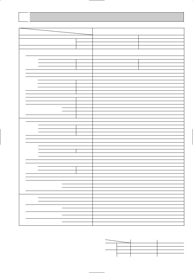
 SPECIFICATIONS
Item |
|
|
|
Service Ref. |
|
Function |
|
|
|
|
|
Capacity |
|
|
|
Btu/h |
|
|
|
|
W |
||
Total input |
|
|
|
||
|
|
|
kW |
||
|
Service Ref. |
|
|
|
|
|
Power supply(phase, cycle, voltage) |
|
|
||
|
|
Input |
|
|
kW |
|
|
Running current |
|
|
A |
|
|
Starting current |
|
|
A |
|
External finish |
|
|
|
|
UNIT |
Heat exchanger |
|
|
|
|
Fan |
Fan(drive) x No. |
|
|
|
|
|
|
|
|
||
INDOOR |
Booster |
Fan motor output |
|
|
kW |
heater |
|
|
kW |
||
|
|
Airflow(Low-High) |
|
|
K/ min (CFM) |
|
|
External static pressure |
|
Pa |
|
|
Operation control & Thermostat |
|
|
||
|
Noise level(Low-High) |
|
|
dB |
|
|
Unit drain pipe O.D. |
|
|
mm(in.) |
|
|
Dimensions |
W |
|
mm(in.) |
|
|
D |
|
mm(in.) |
||
|
Weight |
|
H |
|
mm(in.) |
|
|
|
|
kg(lbs) |
|
|
Service Ref. |
|
|
|
|
|
Power supply (phase, cycle, voltage) |
|
|
||
|
|
Input |
|
|
kW |
|
|
Running current |
|
|
A |
|
|
Starting current |
|
|
A |
|
External finish |
|
|
|
|
|
Refrigerant control |
|
|
|
|
UNIT |
Compressor |
|
|
|
|
|
Model |
|
|
|
|
|
|
|
|
|
|
OUTDOOR |
|
Motor output |
|
|
kW |
|
Starter type |
|
|
|
|
|
|
|
|
|
|
|
|
Protection devices |
|
|
|
|
Heat exchanger |
|
|
|
|
|
Fan |
Fan(drive) x No. |
|
|
|
|
|
Fan motor output |
|
|
kW |
|
|
Airflow |
|
|
K/ min (CFM) |
|
Defrost method |
|
|
|
|
|
Noise level |
|
|
dB |
|
|
|
|
W |
|
mm(in.) |
|
Dimensions |
D |
|
mm(in.) |
|
|
|
|
H |
|
mm(in.) |
|
Weight |
|
|
|
kg(lbs) |
|
Refrigerant |
|
|
kg(lbs) |
|
REFRIGERANT PIPING |
|
Charge |
|
|
|
|
Oil<Model> |
|
|
L |
|
|
|
|
|
||
|
Pipe size O.D. |
Liquid |
|
mm(in.) |
|
|
Gas |
|
mm(in.) |
||
|
|
|
|
||
|
Connection method |
Indoor side |
|||
|
Outdoor side |
||||
|
|
|
|||
|
Between the indoor & outdoor units |
Height difference |
|||
|
|
|
Piping length |
||
PLH-3AK.UK PLH-3AK1.UK
PLH-3AKH.UK PLH-3AKH1.UK
Cooling |
Heating |
26,300 |
28,700[35,800] |
7,700 |
8,400[10,500] |
3.32 |
3.11[5.21] |
PLH-3AK.UK PLH-3AK1.UK
PLH-3AKH.UK PLH-3AKH1.UK
Single, 50Hz, 220-240V |
||
0.17 |
|
0.17[2.27] |
0.81 |
|
0.81[9.47] |
1.00 |
|
1.00[9.7] |
Grille : Munsell 0.70Y 8.59/0.97 |
||
Plate fin coil |
|
|
Turbo fan (direct) x 1 |
||
0.07 |
|
|
15-20(530-705) |
||
0(direct blow) |
|
|
[2.1] |
|
|
Remote controller & built-in |
||
28-34 |
|
|
32(1-1/4) |
|
|
UNIT : 840(33-1/6) |
|
PANEL : 950(37-3/8) |
UNIT : 840(33-1/6) |
|
PANEL : 950(37-3/8) |
UNIT : 258(10-1/8) |
|
PANEL : 30(1-3/16) |
UNIT : 24(53) [26(57)] |
|
PANEL : 5(11) |
PUH-3VKA2.UK / PUH-3YKA2.UK |
||
Single, 50Hz, 220-240V/3, 50Hz, 380-415V(4wires) |
||
3.15 |
|
2.94 |
13.82/5.16 |
|
12.89/4.81 |
58/37 |
|
58/37 |
Munsell 5Y 7/1 Capillary tube Hermetic
NH52VNDT / NH52YDAT 2.2/2.4
Line start w1
Plate fin coil Propeller (direct) x1 0.085
50(1764) Reverse cycle 52 870(34-1/4)
295+24 (11-5/8 add 1) 850(33-1/4)
75(165) R-22 3.2(7.1) 1.6<MS-32> 9.52 (3/8) 15.88(5/8) Flared Flared Max. 50m Max. 50m
w1 V …Internal Thermostat, HP switch
Y …Anti-phase protector, thermal relay, thermal switch, HP switch
Notes: Rating condition (ISO T1<JIS B8616>)
Cooling: Indoor |
: D.B. 27°C, W.B. 19°C |
Outdoor : D.B. 35°C, W.B. 24°C |
|
Heating: Indoor |
: D.B. 20°C |
Outdoor : D.B. 7°C, W.B. 6°C Refrigerant piping length(one way):5m(16ft)
Guaranteed operating range
|
|
Indoor |
Outdoor |
|
Cooling |
Upper limit |
D.B. 35˚C, |
W.B. 22.5˚C |
D.B. 46˚C |
|
Lower limit |
D.B. 21˚C, |
W.B. 15.5˚C |
D.B. -5˚C |
Heating Upper limit |
D.B. 27°C |
D.B. 21˚C, W.B. 15.5˚C |
||
|
Lower limit |
D.B. 20°C |
D.B. -8.5˚C, W.B. -9.5˚C |
|
7
Item |
|
|
|
Service Ref. |
|
|
|
|
|
|
|
Function |
|
|
|
|
|
Capacity |
|
|
|
Btu/h |
|
|
|
|
W |
||
Total input |
|
|
|
||
|
|
|
kW |
||
|
Service Ref. |
|
|
|
|
|
Power supply(phase, cycle,voltage) |
|
|
||
|
|
Input |
|
|
kW |
|
|
Running current |
|
|
A |
|
|
Starting current |
|
|
A |
UNIT |
External finish |
|
|
|
|
Heat exchanger |
|
|
|
||
|
|
|
|
||
|
Fan |
Fan(drive) x No. |
|
|
|
INDOOR |
|
Fan motor output |
|
|
kW |
|
Airflow(Low-High) |
|
|
K/ min (CFM) |
|
|
|
|
|
||
|
|
External static pressure |
|
Pa |
|
|
Booster heater |
|
|
kW |
|
|
Operation control & Thermostat |
|
|
||
|
Noise level(Low-High) |
|
|
dB |
|
|
Unit drain pipe O.D. |
W |
|
mm(in.) |
|
|
|
|
|
mm(in.) |
|
|
Dimensions |
D |
|
mm(in.) |
|
|
|
|
H |
|
mm(in.) |
|
Weight |
|
|
|
kg(lbs) |
|
Service Ref. |
|
|
|
|
|
Power supply (phase, cycle, voltage) |
|
|
||
|
|
Input |
|
|
kW |
|
|
Running current |
|
|
A |
|
|
Starting current |
|
|
A |
|
External finish |
|
|
|
|
|
Refrigerant control |
|
|
|
|
UNIT |
Compressor |
|
|
|
|
|
Model |
|
|
|
|
|
|
|
|
|
|
OUTDOOR |
|
Motor output |
|
|
kW |
|
Starter type |
|
|
|
|
|
|
|
|
|
|
|
|
Protection devices |
|
|
|
|
Heat exchanger |
|
|
|
|
|
Fan |
Fan(drive) x No. |
|
|
|
|
|
Fan motor output |
|
|
kW |
|
|
Airflow |
|
|
K/ min (CFM) |
|
Defrost method |
|
|
|
|
|
Noise level |
W |
|
dB |
|
|
|
|
|
mm(in.) |
|
|
Dimensions |
D |
|
mm(in.) |
|
|
|
|
H |
|
mm(in.) |
|
Weight |
|
|
|
kg(lbs) |
|
Refrigerant |
|
|
|
|
REFRIGERANT PIPING |
|
Charge |
|
|
kg(lbs) |
|
Oil<Model> |
Liquid |
|
L |
|
|
|
|
|||
|
Pipe size O.D. |
|
mm(in.) |
||
|
Gas |
|
mm(in.) |
||
|
|
|
|
||
|
Connection method |
Indoor side |
|||
|
Outdoor side |
||||
|
|
|
|||
|
Between the indoor & outdoor units |
Height difference |
|||
|
|
|
Piping length |
||
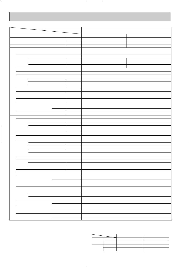
PLH-4AKS.UK PLH-4AKS1.UK
PLH-4AKHS.UK PLH-4AKHS1.UK
Cooling |
Heating |
33,100 |
35,500[44,400] |
9,700 |
10,400[13,000] |
3.46 |
3.45[6.05] |
PLH-4AKS.UK PLH-4AKS1.UK
PLH-4AKHS.UK PLH-4AKHS1.UK
Single, 50Hz, 220-240V |
||
0.26 |
0.26[2.86] |
|
1.25 |
1.25[11.93] |
|
2.0 |
2.0[12.7] |
|
Grille : Munsell 0.70Y 8.59/0.97 |
||
|
Plate fin coil |
|
Turbo fan (direct) x 1 |
||
|
0.120 |
|
20-28(705-990) |
||
|
0(direct blow) |
|
|
[2.6] |
|
Remote controller & built-in |
||
|
33-41 |
|
|
32(1-1/4) |
|
UNIT : 840(33-1/6) |
|
PANEL : 950(37-3/8) |
UNIT : 840(33-1/6) |
|
PANEL : 950(37-3/8) |
UNIT : 298(11-3/4) |
|
PANEL : 30(1-3/16) |
UNIT : 30(66)[32(71)] |
|
PANEL : 5(11) |
PUH-4VKSA.UK / PUH-4YKSA2.UK
Single 50Hz 220V-240V / 3, 50Hz, 380V-415V(4wire)
3.52 |
/ 3.20 |
3.52 |
/ 3.19 |
16.30 / 5.24 |
16.30 / 5.22 |
||
79 |
/ 40 |
79 |
/ 40 |
Munsell 5Y 7/1 Capillary tube Hermetic
NH56VNDT / NH56YDAT 2.7
Line start
Internal thermostat, HP switch / Anti-phase protector, Thermal relay, Thermal switch, HP switch Plate fin coil
Propeller (direct) x2 0.065+0.065 95(3550)
Reverse cycle 54 870(34-1/4)
295+24(11-5/8 add 1) 1258(49-1/2)
94(207) R-22 4.2(9.2) 1.6<MS-32> 9.52(3/8) 19.05(3/4) Flared Flared Max. 50m Max. 50m
Notes: Rating condition (ISO T1<JIS B8616>)
Cooling: Indoor |
: D.B. 27°C, W.B. 19°C |
Outdoor : D.B. 35°C, W.B. 24°C |
|
Heating: Indoor |
: D.B. 20°C |
Outdoor : D.B. 7°C, W.B. 6°C Refrigerant piping length(one way):5m(16ft)
Guaranteed operating range
|
|
Indoor |
Outdoor |
|
Cooling |
Upper limit |
D.B. 35˚C, |
W.B. 22.5˚C |
D.B. 46˚C |
|
Lower limit |
D.B. 21˚C, |
W.B. 15.5˚C |
D.B. -5˚C |
Heating Upper limit |
D.B. 27°C |
D.B. 21˚C, W.B. 15.5˚C |
||
|
Lower limit |
D.B. 20°C |
D.B. -8.5˚C, W.B. -9.5˚C |
|
8
Item |
|
|
|
|
Service Ref. |
|
Function |
|
|
|
|
|
|
Capacity |
|
|
|
|
Btu/h |
|
|
|
|
|
W |
||
Total input |
|
|
|
|
||
|
|
|
|
kW |
||
|
Service Ref. |
|
|
|
|
|
|
Power supply(phase, cycle,voltage) |
|
|
|||
|
|
Input |
|
|
|
kW |
|
|
Running current |
|
A |
||
|
|
Starting current |
|
A |
||
UNIT |
External finish |
|
|
|
|
|
Heat exchanger |
|
|
|
|
||
|
|
|
|
|
||
|
Fan |
Fan(drive) x No. |
|
|
||
INDOOR |
|
Fan motor output |
|
kW |
||
|
Airflow(Low-High) |
|
K/ min (CFM) |
|||
|
|
|
||||
|
|
External static pressure |
|
Pa |
||
|
Booster heater |
|
|
|
kW |
|
|
Operation control & Thermostat |
|
|
|||
|
Noise level(Low-High) |
|
dB |
|||
|
Unit drain pipe O.D. |
|
W |
|
mm(in.) |
|
|
|
|
|
|
mm(in.) |
|
|
Dimensions |
|
D |
|
mm(in.) |
|
|
Weight |
|
|
H |
|
mm(in.) |
|
|
|
|
|
kg(lbs) |
|
|
Service Ref. |
|
|
|
|
|
|
Power supply (phase, cycle, voltage) |
|
|
|||
|
|
Input |
|
|
|
kW |
|
|
Running current |
|
A |
||
|
|
Starting current |
|
A |
||
|
External finish |
|
|
|
|
|
|
Refrigerant control |
|
|
|
|
|
UNIT |
Compressor |
|
|
|
|
|
|
Model |
|
|
|
|
|
|
|
|
|
|
|
|
OUTDOOR |
|
Motor output |
|
kW |
||
|
Starter type |
|
|
|
|
|
|
|
|
|
|
|
|
|
|
Protection devices |
|
|
||
|
Heat exchanger |
|
|
|
|
|
|
Fan |
Fan(drive) x No. |
|
|
||
|
|
Fan motor output |
|
kW |
||
|
|
Airflow |
|
|
|
K/ min (CFM) |
|
Defrost method |
|
|
|
|
|
|
Noise level |
|
W |
|
dB |
|
|
|
|
|
|
mm(in.) |
|
|
Dimensions |
|
D |
|
mm(in.) |
|
|
Weight |
|
|
H |
|
mm(in.) |
|
|
|
|
|
kg(lbs) |
|
|
Refrigerant |
|
|
|
|
|
REFRIGERANT PIPING |
|
Charge |
|
|
|
kg(lbs) |
|
Oil<Model> |
|
Liquid |
|
L |
|
|
|
|
|
|||
|
Pipe size O.D. |
|
|
mm(in.) |
||
|
|
Gas |
|
mm(in.) |
||
|
|
|
|
|
||
|
Connection method |
|
Indoor side |
|||
|
|
Outdoor side |
||||
|
|
|
|
|||
|
Between the indoor & outdoor units |
Height difference |
||||
|
|
|
|
Piping length |
||
Notes: Rating condition (ISO T1<JIS B8616>) |
||||||
|
Cooling: Indoor |
: D.B. 27°C, W.B. 19°C |
||||
|
|
Outdoor : D.B. 35°C, W.B. 24°C |
||||
|
Heating: Indoor |
: D.B. 20°C |
|
|
||
|
|
Outdoor : D.B. 7°C, W.B. 6°C |
||||
|
Refrigerant piping length(one way):5m(16ft) |
|||||
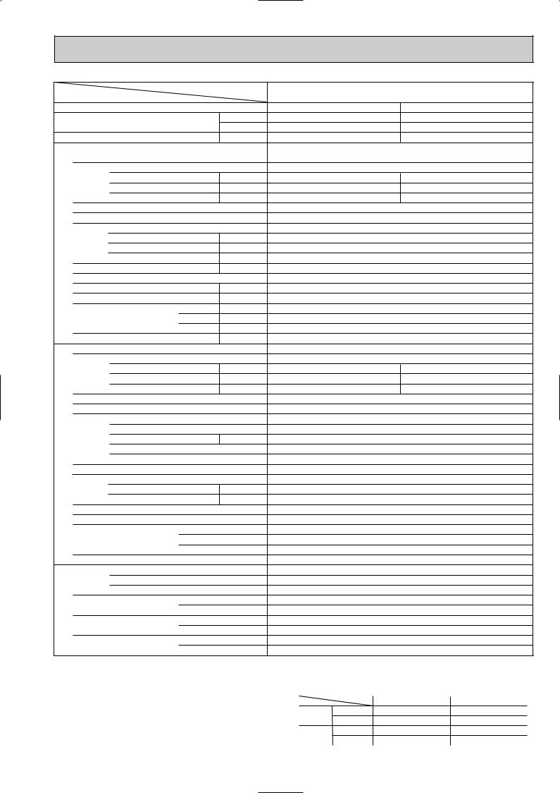
PLH-5AKS.UK PLH-5AKS1.UK
PLH-5AKHS.UK PLH-5AKHS1.UK
Cooling |
Heating |
42,300 |
47,800[58,000] |
12,400 |
14,000[17,000] |
4.51 |
4.46[7.46] |
PLH-5AKS.UK PLH-5AKS1.UK
PLH-5AKHS.UK PLH-5AKHS1.UK
Single, 50Hz, 220-240V |
||
0.30 |
|
0.30[3.30] |
1.43 |
|
1.43[13.77] |
2.0 |
|
2.0[14.3] |
Grille : Munsell 0.70Y 8.59/0.97 |
||
Plate fin coil |
|
|
Turbo fan (direct) x 1 |
||
0.120 |
|
|
22-30(775-1,060) |
||
0(direct blow) |
|
|
[3.0] |
|
|
Remote controller & built-in |
||
35-43 |
|
|
32(1-1/4) |
|
|
UNIT : 840(33-1/16) |
|
PANEL : 950(37-3/8) |
UNIT : 840(33-1/16) |
|
PANEL : 950(37-3/8) |
UNIT : 298(11-3/4) |
|
PANEL : 30(1-3/16) |
UNIT : 30(66) [32(71)] |
|
PANEL : 5(11) |
|
PUH-5YKSA2.UK |
4.21 |
3, 50Hz, 380-415V(4wire) |
4.16 |
|
6.89 |
6.81 |
65 |
65 |
Munsell 5Y 7/1 Capillary tube Hermetic ZR61KC-TFD 3.5
Line start
Internal thermostat, Anti-phase protector, Thermal switch, HP switch Plate fin coil
Propeller (direct) x2 0.085+0.085 95(3550)
Reverse cycle 55 970(38-3/16)
345+24(13-9/16 add 1) 1258(49-1/2)
114(251) R-22 5.4(11.9)
2.13<SONTEX-200LT> 9.52(3/8) 19.05(3/4)
Flared
Flared
Max. 50m
Max. 50m
Guaranteed operating range
|
|
Indoor |
Outdoor |
|
Cooling |
Upper limit |
D.B. 35˚C, |
W.B. 22.5˚C |
D.B. 46˚C |
|
Lower limit |
D.B. 21˚C, |
W.B. 15.5˚C |
D.B. -5˚C |
Heating Upper limit |
D.B. 27°C |
D.B. 21˚C, W.B. 15.5˚C |
||
|
Lower limit |
D.B. 20°C |
D.B. -8.5˚C, W.B. -9.5˚C |
|
9

Item |
|
|
|
|
Service Ref. |
|
Function |
|
|
|
|
|
|
Capacity |
|
|
|
|
Btu/h |
|
|
|
|
|
W |
||
Total input |
|
|
|
|
||
|
|
|
|
kW |
||
|
Service Ref. |
|
|
|
||
|
Power supply(phase, cycle, voltage) |
|
|
|||
|
|
|
Input |
|
|
kW |
|
|
|
Running current |
|
|
A |
|
|
|
Starting current |
|
|
A |
|
External finish |
|
|
|
||
UNIT |
Heat exchanger |
|
|
|
||
Fan |
|
Fan(drive) x No. |
|
|
|
|
|
|
|
|
|||
|
|
|
|
|
||
INDOOR |
Booster |
|
Fan motor output |
|
|
kW |
|
heater |
|
|
kW |
||
|
|
|
Airflow(Low-High) |
|
|
K/ min (CFM) |
|
|
|
External static pressure |
|
Pa |
|
|
Operation control & Thermostat |
|
|
|||
|
Noise level(Low-High) |
|
|
dB |
||
|
Unit drain pipe O.D. |
W |
|
mm(in.) |
||
|
Dimensions |
|
mm(in.) |
|||
|
D |
|
mm(in.) |
|||
|
Weight |
|
|
H |
|
mm(in.) |
|
|
|
|
|
kg(lbs) |
|
|
Service Ref. |
|
|
|
||
|
Power supply (phase, cycle, voltage) |
|
|
|||
|
|
|
Input |
|
|
kW |
|
|
|
Running current |
|
|
A |
|
|
|
Starting current |
|
|
A |
|
External finish |
|
|
|
||
|
Refrigerant control |
|
|
|
||
UNIT |
Compressor |
|
|
|
||
|
|
Model |
|
|
|
|
|
|
Motor output |
|
|
kW |
|
OUTDOOR |
|
|
Starter type |
|
|
|
|
|
|
|
|
|
|
|
|
|
Protection devices |
|
|
|
|
Heat exchanger |
|
|
|
||
|
Fan |
|
Fan(drive) x No. |
|
|
|
|
|
|
|
|
||
|
|
|
Fan motor output |
|
|
kW |
|
|
|
Airflow |
|
|
K/ min (CFM) |
|
Defrost |
|
method |
|
|
|
|
Noise level |
W |
|
dB |
||
|
Dimensions |
|
mm(in.) |
|||
|
D |
|
mm(in.) |
|||
|
Weight |
|
|
H |
|
mm(in.) |
|
|
|
|
|
kg(lbs) |
|
|
Refrigerant |
|
|
|
||
REFRIGERANT PIPING |
|
|
Charge |
|
|
kg(lbs) |
|
|
Oil<Model> |
Liquid |
|
L |
|
|
|
|
|
|||
|
Pipe size O.D. |
|
mm(in.) |
|||
|
Gas |
|
mm(in.) |
|||
|
|
|
|
|
||
|
Connection method |
Indoor side |
||||
|
Outdoor side |
|||||
|
|
|
|
|||
|
Between the indoor & |
Height difference |
||||
|
outdoor units |
Piping length |
||||
Notes: Rating condition (ISO T1<JIS B8616>)
Cooling: Indoor |
: D.B. 27°C, W.B. 19°C |
Outdoor : D.B. 35°C, W.B. 24°C |
|
Heating: Indoor |
: D.B. 20°C |
Outdoor : D.B. 7°C, W.B. 6°C Refrigerant piping length(one way):5m(16ft)
PLH-6AKS.UK PLH-6AKS1.UK
PLH-6AKHS.UK PLH-6AKHS1.UK
Cooling |
Heating |
47,800 |
54,900[65,200] |
14,000 |
16,100[19,100] |
5.07 |
4.92[7.92] |
PLH-6AKS.UK PLH-6AKS1.UK
PLH-6AKHS.UK PLH-6AKHS1.UK
Single, 50Hz, 220-240V |
||
0.34 |
0.34[3.34] |
|
1.64 |
1.64[13.94] |
|
2.0 |
2.0[14.3] |
|
Grille : Munsell 0.70Y 8.59/0.97 |
||
|
Plate fin coil |
|
Turbo fan (direct) x 1 |
||
|
0.120 |
|
22-30(775-1,060) |
||
|
0(direct blow) |
|
|
[3.0] |
|
Remote controller & built-in |
||
|
37-45 |
|
|
32(1-1/4) |
|
UNIT : 840(33-1/16) |
|
PANEL : 950(37-3/8) |
UNIT : 840(33-1/16) |
|
PANEL : 950(37-3/8) |
UNIT : 298(11-3/4) |
|
PANEL : 30(1-3/16) |
UNIT : 32(71)[34(75)] |
|
PANEL : 5(11) |
|
PUH-6YKSA2.UK |
|
3, 50Hz, 380-415V(4wire) |
4.73 |
4.58 |
7.74 |
7.50 |
74 |
74 |
Munsell 5Y 7/1 Capillary tube Hermetic ZR68KC-TFD 4.0
Line start
Internal thermostat, Anti-phase protector, Thermal switch, HP switch Plate fin coil
Propeller (direct) x2 0.10+0.10 100(3530) Reverse cycle
56 970(38-3/16) 345+24(13-9/16 add 1) 1258(49-1/2) 117(258)
R-22 5.0(11.0) 1.774<SONTEX-200LT> 9.52(3/8)
19.05(3/4) Flared Flared Max. 50m Max. 50m
Guaranteed operating range
|
|
Indoor |
Outdoor |
|
Cooling |
Upper limit |
D.B. 35˚C, |
W.B. 22.5˚C |
D.B. 46˚C |
|
Lower limit |
D.B. 21˚C, |
W.B. 15.5˚C |
D.B. -5˚C |
Heating Upper limit |
D.B. 27°C |
D.B. 21˚C, W.B. 15.5˚C |
||
|
Lower limit |
D.B. 20°C |
D.B. -8.5˚C, W.B. -9.5˚C |
|
10
4 
 DATA
DATA
1.PERFORMANCE DATA [50Hz]
1)COOLING CAPACITY(1) PLH-3AK.UK PLH-3AK1.UK PLH-3AKH.UK PLH-3AKH1.UK
Indoor |
|
Indoor |
|
|
|
|
|
Outdoor intake air D.B.(°C) |
|
|
|
|
|
||||
Intake air |
|
Intake air |
|
20 |
|
|
|
|
25 |
|
|
|
30 |
|
|||
D.B.(°C) |
W.B.(°C) |
|
|
|
|
|
|
|
|
|
|
|
|
|
|
|
|
CA |
SHC |
|
SHF |
P.C. |
CA |
SHC |
|
SHF |
P.C. |
CA |
SHC |
|
SHF |
P.C. |
|||
|
|
|
|
|
|
||||||||||||
20 |
|
16 |
7768 |
4972 |
|
0.64 |
2.66 |
7555 |
4835 |
|
0.64 |
2.77 |
7278 |
4658 |
|
0.64 |
2.99 |
20 |
|
18 |
8271 |
4301 |
|
0.52 |
2.71 |
8053 |
4188 |
|
0.52 |
2.83 |
7760 |
4035 |
|
0.52 |
3.06 |
|
|
|
|
|
|
|
|
|
|
|
|
|
|
|
|
|
|
22 |
|
16 |
7768 |
5593 |
|
0.72 |
2.66 |
7555 |
5440 |
|
0.72 |
2.77 |
7278 |
5240 |
|
0.72 |
2.99 |
22 |
|
18 |
8271 |
4963 |
|
0.60 |
2.71 |
8053 |
4832 |
|
0.60 |
2.83 |
7760 |
4656 |
|
0.60 |
3.06 |
22 |
|
20 |
8779 |
4214 |
|
0.48 |
2.77 |
8573 |
4115 |
|
0.48 |
2.89 |
8267 |
3968 |
|
0.48 |
3.12 |
|
|
|
|
|
|
|
|
|
|
|
|
|
|
|
|
|
|
24 |
|
16 |
7768 |
6214 |
|
0.80 |
2.66 |
7555 |
6044 |
|
0.80 |
2.77 |
7278 |
5822 |
|
0.80 |
2.99 |
24 |
|
18 |
8271 |
5624 |
|
0.68 |
2.71 |
8053 |
5476 |
|
0.68 |
2.83 |
7760 |
5277 |
|
0.68 |
3.06 |
24 |
|
20 |
8779 |
4916 |
|
0.56 |
2.77 |
8573 |
4801 |
|
0.56 |
2.89 |
8267 |
4630 |
|
0.56 |
3.12 |
24 |
|
22 |
9293 |
4089 |
|
0.44 |
2.82 |
9115 |
4011 |
|
0.44 |
2.94 |
8799 |
3872 |
|
0.44 |
3.19 |
|
|
|
|
|
|
|
|
|
|
|
|
|
|
|
|
|
|
26 |
|
16 |
7768 |
6836 |
|
0.88 |
2.66 |
7555 |
6649 |
|
0.88 |
2.77 |
7278 |
6404 |
|
0.88 |
2.99 |
26 |
|
18 |
8271 |
6286 |
|
0.76 |
2.71 |
8053 |
6120 |
|
0.76 |
2.83 |
7760 |
5898 |
|
0.76 |
3.06 |
26 |
|
20 |
8779 |
5619 |
|
0.64 |
2.77 |
8573 |
5487 |
|
0.64 |
2.89 |
8267 |
5291 |
|
0.64 |
3.12 |
26 |
|
22 |
9293 |
4832 |
|
0.52 |
2.82 |
9115 |
4740 |
|
0.52 |
2.94 |
8799 |
4576 |
|
0.52 |
3.19 |
|
|
|
|
|
|
|
|
|
|
|
|
|
|
|
|
|
|
27 |
|
16 |
7768 |
7147 |
|
0.92 |
2.66 |
7555 |
6951 |
|
0.92 |
2.77 |
7278 |
6696 |
|
0.92 |
2.99 |
27 |
|
18 |
8271 |
6617 |
|
0.80 |
2.71 |
8053 |
6443 |
|
0.80 |
2.83 |
7760 |
6208 |
|
0.80 |
3.06 |
27 |
|
20 |
8779 |
5970 |
|
0.68 |
2.77 |
8573 |
5830 |
|
0.68 |
2.89 |
8267 |
5622 |
|
0.64 |
3.12 |
27 |
|
22 |
9293 |
5204 |
|
0.56 |
2.82 |
9115 |
5104 |
|
0.56 |
2.94 |
8799 |
4928 |
|
0.52 |
3.19 |
|
|
|
|
|
|
|
|
|
|
|
|
|
|
|
|
|
|
28 |
|
16 |
7768 |
7457 |
|
0.96 |
2.66 |
7555 |
7253 |
|
0.96 |
2.77 |
7278 |
6987 |
|
0.96 |
2.99 |
28 |
|
18 |
8271 |
6948 |
|
0.84 |
2.71 |
8053 |
6765 |
|
0.84 |
2.83 |
7760 |
6518 |
|
0.84 |
3.06 |
28 |
|
20 |
8779 |
6321 |
|
0.72 |
2.77 |
8573 |
6173 |
|
0.72 |
2.89 |
8267 |
5952 |
|
0.72 |
3.12 |
28 |
|
22 |
9293 |
5576 |
|
0.60 |
2.82 |
9115 |
5469 |
|
0.60 |
2.94 |
8799 |
5279 |
|
0.60 |
3.19 |
|
|
|
|
|
|
|
|
|
|
|
|
|
|
|
|
|
|
30 |
|
16 |
7768 |
7768 |
|
1.00 |
2.66 |
7555 |
7555 |
|
1.00 |
2.77 |
7278 |
7278 |
|
1.00 |
2.99 |
30 |
|
18 |
8271 |
7609 |
|
0.92 |
2.71 |
8053 |
7409 |
|
0.92 |
2.83 |
7760 |
7139 |
|
0.92 |
3.06 |
30 |
|
20 |
8779 |
7023 |
|
0.80 |
2.77 |
8573 |
6858 |
|
0.80 |
2.89 |
8267 |
6614 |
|
0.80 |
3.12 |
30 |
|
22 |
9293 |
6319 |
|
0.68 |
2.82 |
9115 |
6198 |
|
0.68 |
2.94 |
8799 |
5983 |
|
0.68 |
3.19 |
|
|
|
|
|
|
|
|
|
|
|
|
|
|
|
|
|
|
32 |
|
16 |
7768 |
7768 |
|
1.00 |
2.66 |
7555 |
7555 |
|
1.00 |
2.77 |
7278 |
7278 |
|
1.00 |
2.99 |
32 |
|
18 |
8271 |
8271 |
|
1.00 |
2.71 |
8053 |
8053 |
|
1.00 |
2.83 |
7760 |
7760 |
|
1.00 |
3.06 |
32 |
|
20 |
8779 |
7726 |
|
0.88 |
2.77 |
8573 |
7544 |
|
0.88 |
2.89 |
8267 |
7275 |
|
0.88 |
3.12 |
32 |
|
22 |
9293 |
7063 |
|
0.76 |
2.82 |
9115 |
6927 |
|
0.76 |
2.94 |
8799 |
6687 |
|
0.76 |
3.19 |
|
|
|
|
|
|
|
|
|
|
|
|
|
|
|
|
|
|
CA |
: Capacity (W) |
|
|
SHC : Sensible heat capacity (W) |
|
|
|
|
|
|
|||||||
P.C. : Power consumption (kW) |
SHF : Sensible heat factor |
|
|
|
|
|
|
|
|
||||||||
11

COOLING CAPACITY(2)
PLH-3AK.UK PLH-3AK1.UK
PLH-3AKH.UK PLH-3AKH1.UK
Indoor |
|
Indoor |
|
|
|
|
|
Outdoor intake air D.B.(°C) |
|
|
|
|
|
||||
Intake air |
Intake air |
|
35 |
|
|
|
40 |
|
|
|
|
45 |
|
||||
D.B.(°C) |
W.B.(°C) |
|
|
|
|
|
|
|
|
|
|
|
|
|
|
|
|
CA |
SHC |
|
SHF |
P.C. |
CA |
SHC |
|
SHF |
P.C. |
CA |
SHC |
|
SHF |
P.C. |
|||
|
|
|
|
|
|
||||||||||||
20 |
|
16 |
6983 |
4469 |
|
0.64 |
3.20 |
6671 |
4269 |
|
0.64 |
3.42 |
6342 |
4059 |
|
0.64 |
3.64 |
20 |
|
18 |
7452 |
3875 |
|
0.52 |
3.28 |
7130 |
3708 |
|
0.52 |
3.51 |
6793 |
3532 |
|
0.52 |
3.73 |
|
|
|
|
|
|
|
|
|
|
|
|
|
|
|
|
|
|
22 |
|
16 |
6983 |
5028 |
|
0.72 |
3.20 |
6671 |
4803 |
|
0.72 |
3.42 |
6342 |
4566 |
|
0.72 |
3.64 |
22 |
|
18 |
7452 |
4471 |
|
0.60 |
3.28 |
7130 |
4278 |
|
0.60 |
3.51 |
6793 |
4076 |
|
0.60 |
3.73 |
22 |
|
20 |
7948 |
3815 |
|
0.48 |
3.36 |
7616 |
3656 |
|
0.48 |
3.60 |
7270 |
3490 |
|
0.48 |
3.84 |
|
|
|
|
|
|
|
|
|
|
|
|
|
|
|
|
|
|
24 |
|
16 |
6983 |
5586 |
|
0.80 |
3.20 |
6671 |
5337 |
|
0.80 |
3.42 |
6342 |
5073 |
|
0.80 |
3.64 |
24 |
|
18 |
7452 |
5067 |
|
0.68 |
3.28 |
7130 |
4848 |
|
0.68 |
3.51 |
6793 |
4619 |
|
0.68 |
3.73 |
24 |
|
20 |
7948 |
4451 |
|
0.56 |
3.36 |
7616 |
4265 |
|
0.56 |
3.60 |
7270 |
4071 |
|
0.56 |
3.84 |
24 |
|
22 |
8470 |
3727 |
|
0.44 |
3.44 |
8128 |
3576 |
|
0.44 |
3.70 |
7773 |
3420 |
|
0.44 |
3.97 |
|
|
|
|
|
|
|
|
|
|
|
|
|
|
|
|
|
|
26 |
|
16 |
6983 |
6145 |
|
0.88 |
3.20 |
6671 |
5870 |
|
0.88 |
3.42 |
6342 |
5581 |
|
0.88 |
3.64 |
26 |
|
18 |
7452 |
5664 |
|
0.76 |
3.28 |
7130 |
5419 |
|
0.76 |
3.51 |
6793 |
5163 |
|
0.76 |
3.73 |
26 |
|
20 |
7948 |
5087 |
|
0.64 |
3.36 |
7616 |
4874 |
|
0.64 |
3.60 |
7270 |
4653 |
|
0.64 |
3.84 |
26 |
|
22 |
8470 |
4405 |
|
0.52 |
3.44 |
8128 |
4227 |
|
0.52 |
3.70 |
7773 |
4042 |
|
0.52 |
3.97 |
|
|
|
|
|
|
|
|
|
|
|
|
|
|
|
|
|
|
27 |
|
16 |
6983 |
6424 |
|
0.92 |
3.20 |
6671 |
6137 |
|
0.92 |
3.42 |
6342 |
5834 |
|
0.92 |
3.64 |
27 |
|
18 |
7452 |
5962 |
|
0.80 |
3.28 |
7130 |
5704 |
|
0.80 |
3.51 |
6793 |
5434 |
|
0.80 |
3.73 |
27 |
|
20 |
7948 |
5405 |
|
0.68 |
3.36 |
7616 |
5179 |
|
0.68 |
3.60 |
7270 |
4944 |
|
0.64 |
3.84 |
27 |
|
22 |
8470 |
4743 |
|
0.56 |
3.44 |
8128 |
4552 |
|
0.56 |
3.70 |
7773 |
4353 |
|
0.52 |
3.97 |
|
|
|
|
|
|
|
|
|
|
|
|
|
|
|
|
|
|
28 |
|
16 |
6983 |
6704 |
|
0.96 |
3.20 |
6671 |
6404 |
|
0.96 |
3.42 |
6342 |
6088 |
|
0.96 |
3.64 |
28 |
|
18 |
7452 |
6260 |
|
0.84 |
3.28 |
7130 |
5989 |
|
0.84 |
3.51 |
6793 |
5706 |
|
0.84 |
3.73 |
28 |
|
20 |
7948 |
5722 |
|
0.72 |
3.36 |
7616 |
5483 |
|
0.72 |
3.60 |
7270 |
5235 |
|
0.72 |
3.84 |
28 |
|
22 |
8470 |
5082 |
|
0.60 |
3.44 |
8128 |
4877 |
|
0.60 |
3.70 |
7773 |
4664 |
|
0.60 |
3.97 |
|
|
|
|
|
|
|
|
|
|
|
|
|
|
|
|
|
|
30 |
|
16 |
6983 |
6983 |
|
1.00 |
3.20 |
6671 |
6671 |
|
1.00 |
3.42 |
6342 |
6342 |
|
1.00 |
3.64 |
30 |
|
18 |
7452 |
6856 |
|
0.92 |
3.28 |
7130 |
6559 |
|
0.92 |
3.51 |
6793 |
6250 |
|
0.92 |
3.73 |
30 |
|
20 |
7948 |
6358 |
|
0.80 |
3.36 |
7616 |
6093 |
|
0.80 |
3.60 |
7270 |
5816 |
|
0.80 |
3.84 |
30 |
|
22 |
8470 |
5760 |
|
0.68 |
3.44 |
8128 |
5527 |
|
0.68 |
3.70 |
7773 |
5286 |
|
0.68 |
3.97 |
|
|
|
|
|
|
|
|
|
|
|
|
|
|
|
|
|
|
32 |
|
16 |
6983 |
6983 |
|
1.00 |
3.20 |
6671 |
6671 |
|
1.00 |
3.42 |
6342 |
6342 |
|
1.00 |
3.64 |
32 |
|
18 |
7452 |
7452 |
|
1.00 |
3.28 |
7130 |
7130 |
|
1.00 |
3.51 |
6793 |
6793 |
|
1.00 |
3.73 |
32 |
|
20 |
7948 |
6994 |
|
0.88 |
3.36 |
7616 |
6702 |
|
0.88 |
3.60 |
7270 |
6398 |
|
0.88 |
3.84 |
32 |
|
22 |
8470 |
6437 |
|
0.76 |
3.44 |
8128 |
6178 |
|
0.76 |
3.70 |
7773 |
5908 |
|
0.76 |
3.97 |
|
|
|
|
|
|
|
|
|
|
|
|
|
|
|
|
|
|
CA |
: Capacity (W) |
|
|
SHC : Sensible heat capacity (W) |
|
|
|
|
|
|
|
||||||
P.C. : Power consumption (kW) |
SHF : Sensible heat factor |
|
|
|
|
|
|
|
|||||||||
12

COOLING CAPACITY(3)
PLH-4AKS.UK PLH-4AKS1.UK
PLH-4AKHS.UK PLH-4AKHS1.UK
Indoor |
|
Indoor |
|
|
|
|
|
Outdoor intake air D.B.(°C) |
|
|
|
|
|
||||
|
|
|
|
|
|
|
|
|
|
|
|
|
|
|
|
||
Intake air |
|
Intake air |
|
20 |
|
|
|
25 |
|
|
|
|
30 |
|
|||
D.B.(°C) |
W.B.(°C) |
|
|
|
|
|
|
|
|
|
|
|
|
|
|
|
|
CA |
SHC |
|
SHF |
P.C. |
CA |
SHC |
|
SHF |
P.C. |
CA |
SHC |
|
SHF |
P.C. |
|||
|
|
|
|
|
|
||||||||||||
20 |
|
16 |
9786 |
6752 |
|
0.69 |
2.77 |
9518 |
6567 |
|
0.69 |
2.89 |
9168 |
6326 |
|
0.69 |
3.11 |
20 |
|
18 |
10419 |
5939 |
|
0.57 |
2.83 |
10145 |
5783 |
|
0.57 |
2.95 |
9775 |
5572 |
|
0.57 |
3.18 |
|
|
|
|
|
|
|
|
|
|
|
|
|
|
|
|
|
|
22 |
|
16 |
9786 |
7535 |
|
0.77 |
2.77 |
9518 |
7329 |
|
0.77 |
2.89 |
9168 |
7059 |
|
0.77 |
3.11 |
22 |
|
18 |
10419 |
6773 |
|
0.65 |
2.83 |
10145 |
6594 |
|
0.65 |
2.95 |
9775 |
6354 |
|
0.65 |
3.18 |
22 |
|
20 |
11060 |
5862 |
|
0.53 |
2.88 |
10800 |
5724 |
|
0.53 |
3.01 |
10414 |
5520 |
|
0.53 |
3.25 |
|
|
|
|
|
|
|
|
|
|
|
|
|
|
|
|
|
|
24 |
|
16 |
9786 |
8318 |
|
0.85 |
2.77 |
9518 |
8090 |
|
0.85 |
2.89 |
9168 |
7793 |
|
0.85 |
3.11 |
24 |
|
18 |
10419 |
7606 |
|
0.73 |
2.83 |
10145 |
7406 |
|
0.73 |
2.95 |
9775 |
7136 |
|
0.73 |
3.18 |
24 |
|
20 |
11060 |
6746 |
|
0.61 |
2.88 |
10800 |
6588 |
|
0.61 |
3.01 |
10414 |
6353 |
|
0.61 |
3.25 |
24 |
|
22 |
11707 |
5736 |
|
0.49 |
2.94 |
11482 |
5626 |
|
0.49 |
3.07 |
11085 |
5431 |
|
0.49 |
3.32 |
|
|
|
|
|
|
|
|
|
|
|
|
|
|
|
|
|
|
26 |
|
16 |
9786 |
9101 |
|
0.93 |
2.77 |
9518 |
8852 |
|
0.93 |
2.89 |
9168 |
8526 |
|
0.93 |
3.11 |
26 |
|
18 |
10419 |
8440 |
|
0.81 |
2.83 |
10145 |
8217 |
|
0.81 |
2.95 |
9775 |
7918 |
|
0.81 |
3.18 |
26 |
|
20 |
11060 |
7631 |
|
0.69 |
2.88 |
10800 |
7452 |
|
0.69 |
3.01 |
10414 |
7186 |
|
0.69 |
3.25 |
26 |
|
22 |
11707 |
6673 |
|
0.57 |
2.94 |
11482 |
6545 |
|
0.57 |
3.07 |
11085 |
6318 |
|
0.57 |
3.32 |
|
|
|
|
|
|
|
|
|
|
|
|
|
|
|
|
|
|
27 |
|
16 |
9786 |
9492 |
|
0.97 |
2.77 |
9518 |
9232 |
|
0.97 |
2.89 |
9168 |
8893 |
|
0.97 |
3.11 |
27 |
|
18 |
10419 |
8856 |
|
0.85 |
2.83 |
10145 |
8623 |
|
0.85 |
2.95 |
9775 |
8309 |
|
0.85 |
3.18 |
27 |
|
20 |
11060 |
8073 |
|
0.73 |
2.88 |
10800 |
7884 |
|
0.73 |
3.01 |
10414 |
7602 |
|
0.73 |
3.25 |
27 |
|
22 |
11707 |
7141 |
|
0.61 |
2.94 |
11482 |
7004 |
|
0.61 |
3.07 |
11085 |
6762 |
|
0.61 |
3.32 |
|
|
|
|
|
|
|
|
|
|
|
|
|
|
|
|
|
|
28 |
|
16 |
9786 |
9786 |
|
1.00 |
2.77 |
9518 |
9518 |
|
1.00 |
2.89 |
9168 |
9168 |
|
1.00 |
3.11 |
28 |
|
18 |
10419 |
9273 |
|
0.89 |
2.83 |
10145 |
9029 |
|
0.89 |
2.95 |
9775 |
8700 |
|
0.89 |
3.18 |
28 |
|
20 |
11060 |
8516 |
|
0.77 |
2.88 |
10800 |
8316 |
|
0.77 |
3.01 |
10414 |
8019 |
|
0.77 |
3.25 |
28 |
|
22 |
11707 |
7609 |
|
0.65 |
2.94 |
11482 |
7464 |
|
0.65 |
3.07 |
11085 |
7205 |
|
0.65 |
3.32 |
|
|
|
|
|
|
|
|
|
|
|
|
|
|
|
|
|
|
30 |
|
16 |
9786 |
9786 |
|
1.00 |
2.77 |
9518 |
9518 |
|
1.00 |
2.89 |
9168 |
.9168 |
|
1.00 |
3.11 |
30 |
|
18 |
10419 |
10107 |
|
0.97 |
2.83 |
10145 |
9841 |
|
0.97 |
2.95 |
9775 |
9482 |
|
0.97 |
3.18 |
30 |
|
20 |
11060 |
9401 |
|
0.85 |
2.88 |
10800 |
9180 |
|
0.85 |
3.01 |
10414 |
8852 |
|
0.85 |
3.25 |
30 |
|
22 |
11707 |
8546 |
|
0.73 |
2.94 |
11482 |
8382 |
|
0.73 |
3.07 |
11085 |
8092 |
|
0.73 |
3.32 |
|
|
|
|
|
|
|
|
|
|
|
|
|
|
|
|
|
|
32 |
|
16 |
9786 |
9786 |
|
1.00 |
2.77 |
9518 |
9518 |
|
1.00 |
2.89 |
9168 |
9168 |
|
1.00 |
3.11 |
32 |
|
18 |
10419 |
10419 |
|
1.00 |
2.83 |
10145 |
10145 |
|
1.00 |
2.95 |
9775 |
9775 |
|
1.00 |
3.18 |
32 |
|
20 |
11060 |
10285 |
|
0.93 |
2.88 |
10800 |
10044 |
|
0.93 |
3.01 |
10414 |
9685 |
|
0.93 |
3.25 |
32 |
|
22 |
11707 |
9483 |
|
0.81 |
2.94 |
11482 |
9301 |
|
0.81 |
3.07 |
11085 |
8979 |
|
0.81 |
3.32 |
|
|
|
|
|
|
|
|
|
|
|
|
|
|
|
|
|
|
CA |
: Capacity (W) |
|
|
SHC : Sensible heat capacity (W) |
|
|
|
|
|
|
|
||||||
P.C. : Power consumption (kW) |
SHF : Sensible heat factor |
|
|
|
|
|
|
|
|||||||||
13

COOLING CAPACITY(4)
PLH-4AKS.UK PLH-4AKS1.UK
PLH-4AKHS.UK PLH-4AKHS1.UK
Indoor |
|
Indoor |
|
|
|
|
|
Outdoor intake air D.B.(°C) |
|
|
|
|
|
||||
|
|
|
|
|
|
|
|
|
|
|
|
|
|
|
|
||
Intake air |
|
Intake air |
|
35 |
|
|
|
40 |
|
|
|
|
45 |
|
|||
D.B.(°C) |
W.B.(°C) |
|
|
|
|
|
|
|
|
|
|
|
|
|
|
|
|
CA |
SHC |
|
SHF |
P.C. |
CA |
SHC |
|
SHF |
P.C. |
CA |
SHC |
|
SHF |
P.C. |
|||
|
|
|
|
|
|
||||||||||||
20 |
|
16 |
8797 |
6070 |
|
0.69 |
3.34 |
8404 |
5798 |
|
0.69 |
3.56 |
7989 |
5512 |
|
0.69 |
3.79 |
20 |
|
18 |
9388 |
5351 |
|
0.57 |
3.42 |
8982 |
5120 |
|
0.57 |
3.65 |
8558 |
4878 |
|
0.57 |
3.89 |
|
|
|
|
|
|
|
|
|
|
|
|
|
|
|
|
|
|
22 |
|
16 |
8797 |
6773 |
|
0.77 |
3.34 |
8404 |
6471 |
|
0.77 |
3.56 |
7989 |
6151 |
|
0.77 |
3.79 |
22 |
|
18 |
9388 |
6102 |
|
0.65 |
3.42 |
8982 |
5838 |
|
0.65 |
3.65 |
8558 |
5562 |
|
0.65 |
3.89 |
22 |
|
20 |
10012 |
5307 |
|
0.53 |
3.50 |
9594 |
5085 |
|
0.53 |
3.75 |
9159 |
4854 |
|
0.53 |
4.00 |
|
|
|
|
|
|
|
|
|
|
|
|
|
|
|
|
|
|
24 |
|
16 |
8797 |
7477 |
|
0.85 |
3.34 |
8404 |
7143 |
|
0.85 |
3.56 |
7989 |
6790 |
|
0.85 |
3.79 |
24 |
|
18 |
9388 |
6853 |
|
0.73 |
3.42 |
8982 |
6557 |
|
0.73 |
3.65 |
8558 |
6247 |
|
0.73 |
3.89 |
24 |
|
20 |
10012 |
6107 |
|
0.61 |
3.50 |
9594 |
5852 |
|
0.61 |
3.75 |
9159 |
5587 |
|
0.61 |
4.00 |
24 |
|
22 |
10670 |
5228 |
|
0.49 |
3.59 |
10240 |
5017 |
|
0.49 |
3.86 |
9792 |
4798 |
|
0.49 |
4.14 |
|
|
|
|
|
|
|
|
|
|
|
|
|
|
|
|
|
|
26 |
|
16 |
8797 |
8181 |
|
0.93 |
3.34 |
8404 |
7815 |
|
0.93 |
3.56 |
7989 |
7430 |
|
0.93 |
3.79 |
26 |
|
18 |
9388 |
7604 |
|
0.81 |
3.42 |
8982 |
7275 |
|
0.81 |
3.65 |
8558 |
6932 |
|
0.81 |
3.89 |
26 |
|
20 |
10012 |
6908 |
|
0.69 |
3.50 |
9594 |
6620 |
|
0.69 |
3.75 |
9159 |
6320 |
|
0.69 |
4.00 |
26 |
|
22 |
10670 |
6082 |
|
0.57 |
3.59 |
10240 |
5837 |
|
0.57 |
3.86 |
9792 |
5582 |
|
0.57 |
4.14 |
|
|
|
|
|
|
|
|
|
|
|
|
|
|
|
|
|
|
27 |
|
16 |
8797 |
8533 |
|
0.97 |
3.34 |
8404 |
8151 |
|
0.97 |
3.56 |
7989 |
7749 |
|
0.97 |
3.79 |
27 |
|
18 |
9388 |
7980 |
|
0.85 |
3.42 |
8982 |
7634 |
|
0.85 |
3.65 |
8558 |
7274 |
|
0.85 |
3.89 |
27 |
|
20 |
10012 |
7309 |
|
0.73 |
3.50 |
9594 |
7003 |
|
0.73 |
3.75 |
9159 |
6686 |
|
0.73 |
4.00 |
27 |
|
22 |
10670 |
6509 |
|
0.61 |
3.59 |
10240 |
6246 |
|
0.61 |
3.86 |
9792 |
5973 |
|
0.61 |
4.14 |
|
|
|
|
|
|
|
|
|
|
|
|
|
|
|
|
|
|
28 |
|
16 |
8797 |
8797 |
|
1.00 |
3.34 |
8404 |
8404 |
|
1.00 |
3.56 |
7989 |
7989 |
|
1.00 |
3.79 |
28 |
|
18 |
9388 |
8355 |
|
0.89 |
3.42 |
8982 |
7994 |
|
0.89 |
3.65 |
8558 |
7616 |
|
0.89 |
3.89 |
28 |
|
20 |
10012 |
7709 |
|
0.77 |
3.50 |
9594 |
7387 |
|
0.77 |
3.75 |
9159 |
7052 |
|
0.77 |
4.00 |
28 |
|
22 |
10670 |
6936 |
|
0.65 |
3.59 |
10240 |
6656 |
|
0.65 |
3.86 |
9792 |
6365 |
|
0.65 |
4.14 |
|
|
|
|
|
|
|
|
|
|
|
|
|
|
|
|
|
|
30 |
|
16 |
8797 |
8797 |
|
1.00 |
3.34 |
8404 |
8404 |
|
1.00 |
3.56 |
7989 |
7989 |
|
1.00 |
3.79 |
30 |
|
18 |
9388 |
9106 |
|
0.97 |
3.42 |
8982 |
8712 |
|
0.97 |
3.65 |
8558 |
8301 |
|
0.97 |
3.89 |
30 |
|
20 |
10012 |
8510 |
|
0.85 |
3.50 |
9594 |
8155 |
|
0.85 |
3.75 |
9159 |
7785 |
|
0.85 |
4.00 |
30 |
|
22 |
10670 |
7789 |
|
0.73 |
3.59 |
10240 |
7475 |
|
0.73 |
3.86 |
9792 |
7148 |
|
0.73 |
4.14 |
|
|
|
|
|
|
|
|
|
|
|
|
|
|
|
|
|
|
32 |
|
16 |
8797 |
8797 |
|
1.00 |
3.34 |
8404 |
8404 |
|
1.00 |
3.56 |
7989 |
7989 |
|
1.00 |
3.79 |
32 |
|
18 |
9388 |
9388 |
|
1.00 |
3.42 |
8982 |
8982 |
|
1.00 |
3.65 |
8558 |
8558 |
|
1.00 |
3.89 |
32 |
|
20 |
10012 |
9311 |
|
0.93 |
3.50 |
9594 |
8922 |
|
0.93 |
3.75 |
9159 |
8518 |
|
0.93 |
4.00 |
32 |
|
22 |
10670 |
8643 |
|
0.81 |
3.59 |
10240 |
8294 |
|
0.81 |
3.86 |
9792 |
7932 |
|
0.81 |
4.14 |
|
|
|
|
|
|
|
|
|
|
|
|
|
|
|
|
|
|
CA |
: Capacity (W) |
|
|
SHC : Sensible heat capacity (W) |
|
|
|
|
|
|
|
||||||
P.C. : Power consumption (kW) |
SHF : Sensible heat factor |
|
|
|
|
|
|
|
|||||||||
14

COOLING CAPACITY(5)
PLH-5AKS.UK PLH-5AKS1.UK
PLH-5AKHS.UK PLH-5AKHS1.UK
Indoor |
|
Indoor |
|
|
|
|
|
Outdoor intake air D.B.(°C) |
|
|
|
|
|
||||
Intake air |
|
Intake air |
|
20 |
|
|
|
25 |
|
|
|
|
30 |
|
|||
D.B.(°C) |
W.B.(°C) |
|
|
|
|
|
|
|
|
|
|
|
|
|
|
|
|
CA |
SHC |
|
SHF |
P.C. |
CA |
SHC |
|
SHF |
P.C. |
CA |
SHC |
|
SHF |
P.C. |
|||
|
|
|
|
|
|
||||||||||||
20 |
|
16 |
12510 |
7881 |
|
0.63 |
3.61 |
12167 |
7665 |
|
0.63 |
3.77 |
11720 |
7384 |
|
0.63 |
4.06 |
20 |
|
18 |
13319 |
6793 |
|
0.51 |
3.69 |
12969 |
6614 |
|
0.51 |
3.85 |
12496 |
6373 |
|
0.51 |
4.15 |
|
|
|
|
|
|
|
|
|
|
|
|
|
|
|
|
|
|
22 |
|
16 |
12510 |
8882 |
|
0.71 |
3.61 |
12167 |
8639 |
|
0.71 |
3.77 |
11720 |
8321 |
|
0.71 |
4.06 |
22 |
|
18 |
13319 |
7858 |
|
0.59 |
3.69 |
12969 |
7652 |
|
0.59 |
3.85 |
12496 |
7373 |
|
0.59 |
4.15 |
22 |
|
20 |
14138 |
6645 |
|
0.47 |
3.76 |
13806 |
6489 |
|
0.47 |
3.92 |
13313 |
6257 |
|
0.47 |
4.24 |
|
|
|
|
|
|
|
|
|
|
|
|
|
|
|
|
|
|
24 |
|
16 |
12510 |
9883 |
|
0.79 |
3.61 |
12167 |
9612 |
|
0.79 |
3.77 |
11720 |
9259 |
|
0.79 |
4.06 |
24 |
|
18 |
13319 |
8924 |
|
0.67 |
3.69 |
12969 |
8689 |
|
0.67 |
3.85 |
12496 |
8373 |
|
0.67 |
4.15 |
24 |
|
20 |
14138 |
7776 |
|
0.55 |
3.76 |
13806 |
7593 |
|
0.55 |
3.92 |
13313 |
7322 |
|
0.55 |
4.24 |
24 |
|
22 |
14965 |
6435 |
|
0.43 |
3.83 |
14679 |
6312 |
|
0.43 |
4.00 |
14170 |
6093 |
|
0.43 |
4.33 |
|
|
|
|
|
|
|
|
|
|
|
|
|
|
|
|
|
|
26 |
|
16 |
12510 |
10883 |
|
0.87 |
3.61 |
12167 |
10585 |
|
0.87 |
3.77 |
11720 |
10196 |
|
0.87 |
4.06 |
26 |
|
18 |
13319 |
9990 |
|
0.75 |
3.69 |
12969 |
9727 |
|
0.75 |
3.85 |
12496 |
9372 |
|
0.75 |
4.15 |
26 |
|
20 |
14138 |
8907 |
|
0.63 |
3.76 |
13806 |
8698 |
|
0.63 |
3.92 |
13313 |
8387 |
|
0.63 |
4.24 |
26 |
|
22 |
14965 |
7632 |
|
0.51 |
3.83 |
14679 |
7486 |
|
0.51 |
4.00 |
14170 |
7227 |
|
0.51 |
4.33 |
|
|
|
|
|
|
|
|
|
|
|
|
|
|
|
|
|
|
27 |
|
16 |
12510 |
11384 |
|
0.91 |
3.61 |
12167 |
11072 |
|
0.91 |
3.77 |
11720 |
10665 |
|
0.91 |
4.06 |
27 |
|
18 |
13319 |
10522 |
|
0.79 |
3.69 |
12969 |
10245 |
|
0.79 |
3.85 |
12496 |
9872 |
|
0.79 |
4.15 |
27 |
|
20 |
14138 |
9472 |
|
0.67 |
3.76 |
13806 |
9250 |
|
0.67 |
3.92 |
13313 |
8920 |
|
0.67 |
4.24 |
27 |
|
22 |
14965 |
8231 |
|
0.55 |
3.83 |
14679 |
8073 |
|
0.55 |
4.00 |
14170 |
7794 |
|
0.55 |
4.33 |
|
|
|
|
|
|
|
|
|
|
|
|
|
|
|
|
|
|
28 |
|
16 |
12510 |
11884 |
|
0.95 |
3.61 |
12167 |
11559 |
|
0.95 |
3.77 |
11720 |
11134 |
|
0.95 |
4.06 |
28 |
|
18 |
13319 |
11055 |
|
0.83 |
3.69 |
12969 |
10764 |
|
0.83 |
3.85 |
12496 |
10372 |
|
0.83 |
4.15 |
28 |
|
20 |
14138 |
10038 |
|
0.71 |
3.76 |
13806 |
9802 |
|
0.71 |
3.92 |
13313 |
9452 |
|
0.71 |
4.24 |
28 |
|
22 |
14965 |
8830 |
|
0.59 |
3.83 |
14679 |
8660 |
|
0.59 |
4.00 |
14170 |
8360 |
|
0.59 |
4.33 |
|
|
|
|
|
|
|
|
|
|
|
|
|
|
|
|
|
|
30 |
|
16 |
12510 |
12510 |
|
1.00 |
3.61 |
12167 |
12167 |
|
1.00 |
3.77 |
11720 |
11720 |
|
1.00 |
4.06 |
30 |
|
18 |
13319 |
12121 |
|
0.91 |
3.69 |
12969 |
11802 |
|
0.91 |
3.85 |
12496 |
11372 |
|
0.91 |
4.15 |
30 |
|
20 |
14138 |
11169 |
|
0.79 |
3.76 |
13806 |
10907 |
|
0.79 |
3.92 |
13313 |
10517 |
|
0.79 |
4.24 |
30 |
|
22 |
14965 |
10027 |
|
0.67 |
3.83 |
14679 |
9835 |
|
0.67 |
4.00 |
14170 |
9494 |
|
0.67 |
4.33 |
|
|
|
|
|
|
|
|
|
|
|
|
|
|
|
|
|
|
32 |
|
16 |
12510 |
12510 |
|
1.00 |
3.61 |
12167 |
12167 |
|
1.00 |
3.77 |
11720 |
11720 |
|
1.00 |
4.06 |
32 |
|
18 |
13319 |
13186 |
|
0.99 |
3.69 |
12969 |
12839 |
|
0.99 |
3.85 |
12496 |
12371 |
|
0.99 |
4.15 |
32 |
|
20 |
14138 |
12300 |
|
0.87 |
3.76 |
13806 |
12011 |
|
0.87 |
3.92 |
13313 |
11582 |
|
0.87 |
4.24 |
32 |
|
22 |
14965 |
11224 |
|
0.75 |
3.83 |
14679 |
11009 |
|
0.75 |
4.00 |
14170 |
10628 |
|
0.75 |
4.33 |
|
|
|
|
|
|
|
|
|
|
|
|
|
|
|
|
|
|
CA |
: Capacity (W) |
|
|
SHC : Sensible heat capacity (W) |
|
|
|
|
|
|
|
||||||
P.C. : Power consumption (kW) |
SHF : Sensible heat factor |
|
|
|
|
|
|
|
|||||||||
15

COOLING CAPACITY(6)
PLH-5AKS.UK PLH-5AKS1.UK
PLH-5AKHS.UK PLH-5AKHS1.UK
Indoor |
|
Indoor |
|
|
|
|
|
Outdoor intake air D.B.(°C) |
|
|
|
|
|
||||
|
|
|
|
|
|
|
|
|
|
|
|
|
|
|
|
||
Intake air |
Intake air |
|
35 |
|
|
|
40 |
|
|
|
|
45 |
|
||||
D.B.(°C) |
W.B.(°C) |
|
|
|
|
|
|
|
|
|
|
|
|
|
|
|
|
CA |
SHC |
|
SHF |
P.C. |
CA |
SHC |
|
SHF |
P.C. |
CA |
SHC |
|
SHF |
P.C. |
|||
|
|
|
|
|
|
||||||||||||
20 |
|
16 |
11245 |
7085 |
|
0.63 |
4.35 |
10743 |
6768 |
|
0.63 |
4.64 |
10212 |
6434 |
|
0.63 |
4.94 |
20 |
|
18 |
12001 |
6120 |
|
0.51 |
4.46 |
11482 |
5856 |
|
0.51 |
4.76 |
10939 |
5579 |
|
0.51 |
5.07 |
|
|
|
|
|
|
|
|
|
|
|
|
|
|
|
|
|
|
22 |
|
16 |
11245 |
7984 |
|
0.71 |
4.35 |
10743 |
7627 |
|
0.71 |
4.64 |
10212 |
7251 |
|
0.71 |
4.94 |
22 |
|
18 |
12001 |
7080 |
|
0.59 |
4.46 |
11482 |
6774 |
|
0.59 |
4.76 |
10939 |
6454 |
|
0.59 |
5.07 |
22 |
|
20 |
12799 |
6016 |
|
0.47 |
4.56 |
12264 |
5764 |
|
0.47 |
4.89 |
11708 |
5503 |
|
0.47 |
5.22 |
|
|
|
|
|
|
|
|
|
|
|
|
|
|
|
|
|
|
24 |
|
16 |
11245 |
8884 |
|
0.79 |
4.35 |
10743 |
8487 |
|
0.79 |
4.64 |
10212 |
8068 |
|
0.79 |
4.94 |
24 |
|
18 |
12001 |
8041 |
|
0.67 |
4.46 |
11482 |
7693 |
|
0.67 |
4.76 |
10939 |
7329 |
|
0.67 |
5.07 |
24 |
|
20 |
12799 |
7040 |
|
0.55 |
4.56 |
12264 |
6745 |
|
0.55 |
4.89 |
11708 |
6439 |
|
0.55 |
5.22 |
24 |
|
22 |
13640 |
5865 |
|
0.43 |
4.67 |
13090 |
5629 |
|
0.43 |
5.03 |
12518 |
5383 |
|
0.43 |
5.39 |
|
|
|
|
|
|
|
|
|
|
|
|
|
|
|
|
|
|
26 |
|
16 |
11245 |
9783 |
|
0.87 |
4.35 |
10743 |
9346 |
|
0.87 |
4.64 |
10212 |
8885 |
|
0.87 |
4.94 |
26 |
|
18 |
12001 |
9001 |
|
0.75 |
4.46 |
11482 |
8611 |
|
0.75 |
4.76 |
10939 |
8205 |
|
0.75 |
5.07 |
26 |
|
20 |
12799 |
8064 |
|
0.63 |
4.56 |
12264 |
7726 |
|
0.63 |
4.89 |
11708 |
7376 |
|
0.63 |
5.22 |
26 |
|
22 |
13640 |
6957 |
|
0.51 |
4.67 |
13090 |
6676 |
|
0.51 |
5.03 |
12518 |
6384 |
|
0.51 |
5.39 |
|
|
|
|
|
|
|
|
|
|
|
|
|
|
|
|
|
|
27 |
|
16 |
11245 |
10233 |
|
0.91 |
4.35 |
10743 |
9776 |
|
0.91 |
4.64 |
10212 |
9293 |
|
0.91 |
4.94 |
27 |
|
18 |
12001 |
9481 |
|
0.79 |
4.46 |
11482 |
9071 |
|
0.79 |
4.76 |
10939 |
8642 |
|
0.79 |
5.07 |
27 |
|
20 |
12799 |
8575 |
|
0.67 |
4.56 |
12264 |
8217 |
|
0.67 |
4.89 |
11708 |
7844 |
|
0.67 |
5.22 |
27 |
|
22 |
13640 |
7502 |
|
0.55 |
4.67 |
13090 |
7199 |
|
0.55 |
5.03 |
12518 |
6885 |
|
0.55 |
5.39 |
|
|
|
|
|
|
|
|
|
|
|
|
|
|
|
|
|
|
28 |
|
16 |
11245 |
10683 |
|
0.95 |
4.35 |
10743 |
10206 |
|
0.95 |
4.64 |
10212 |
9702 |
|
0.95 |
4.94 |
28 |
|
18 |
12001 |
9961 |
|
0.83 |
4.46 |
11482 |
9530 |
|
0.83 |
4.76 |
10939 |
9080 |
|
0.83 |
5.07 |
28 |
|
20 |
12799 |
9087 |
|
0.71 |
4.56 |
12264 |
8708 |
|
0.71 |
4.89 |
11708 |
8313 |
|
0.71 |
5.22 |
28 |
|
22 |
13640 |
8048 |
|
0.59 |
4.67 |
13090 |
7723 |
|
0.59 |
5.03 |
12518 |
7386 |
|
0.59 |
5.39 |
|
|
|
|
|
|
|
|
|
|
|
|
|
|
|
|
|
|
30 |
|
16 |
11245 |
11245 |
|
1.00 |
4.35 |
10743 |
10743 |
|
1.00 |
4.64 |
10212 |
10212 |
|
1.00 |
4.94 |
30 |
|
18 |
12001 |
10921 |
|
0.91 |
4.46 |
11482 |
10448 |
|
0.91 |
4.76 |
10939 |
9955 |
|
0.91 |
5.07 |
30 |
|
20 |
12799 |
10111 |
|
0.79 |
4.56 |
12264 |
9689 |
|
0.79 |
4.89 |
11708 |
9249 |
|
0.79 |
5.22 |
30 |
|
22 |
13640 |
9139 |
|
0.67 |
4.67 |
13090 |
8770 |
|
0.67 |
5.03 |
12518 |
8387 |
|
0.67 |
5.39 |
|
|
|
|
|
|
|
|
|
|
|
|
|
|
|
|
|
|
32 |
|
16 |
11245 |
11245 |
|
1.00 |
4.35 |
10743 |
10743 |
|
1.00 |
4.64 |
10212 |
10212 |
|
1.00 |
4.94 |
32 |
|
18 |
12001 |
11881 |
|
0.99 |
4.46 |
11482 |
11367 |
|
0.99 |
4.76 |
10939 |
10830 |
|
0.99 |
5.07 |
32 |
|
20 |
12799 |
11135 |
|
0.87 |
4.56 |
12264 |
10670 |
|
0.87 |
4.89 |
11708 |
10186 |
|
0.87 |
5.22 |
32 |
|
22 |
13640 |
10230 |
|
0.75 |
4.67 |
13090 |
9817 |
|
0.75 |
5.03 |
12518 |
9389 |
|
0.75 |
5.39 |
|
|
|
|
|
|
|
|
|
|
|
|
|
|
|
|
|
|
CA |
: Capacity (W) |
|
|
SHC : Sensible heat capacity (W) |
|
|
|
|
|
|
|
||||||
P.C. : Power consumption (kW) |
SHF : Sensible heat factor |
|
|
|
|
|
|
|
|||||||||
16

COOLING CAPACITY(7)
PLH-6AKS.UK PLH-6AKS1.UK
PLH-6AKHS.UK PLH-6AKHS1.UK
Indoor |
|
Indoor |
|
|
|
|
|
Outdoor intake air D.B.(°C) |
|
|
|
|
|
||||
|
|
|
|
|
|
|
|
|
|
|
|
|
|
|
|
||
Intake air |
|
Intake air |
|
20 |
|
|
|
25 |
|
|
|
|
30 |
|
|||
D.B.(°C) |
W.B.(°C) |
|
|
|
|
|
|
|
|
|
|
|
|
|
|
|
|
CA |
SHC |
|
SHF |
P.C. |
CA |
SHC |
|
SHF |
P.C. |
CA |
SHC |
|
SHF |
P.C. |
|||
|
|
|
|
|
|
||||||||||||
20 |
|
16 |
14124 |
8616 |
|
0.61 |
4.06 |
13737 |
8380 |
|
0.61 |
4.24 |
13232 |
8072 |
|
0.61 |
4.56 |
20 |
|
18 |
15038 |
7369 |
|
0.49 |
4.15 |
14642 |
7175 |
|
0.49 |
4.32 |
14109 |
6913 |
|
0.49 |
4.67 |
|
|
|
|
|
|
|
|
|
|
|
|
|
|
|
|
|
|
22 |
|
16 |
14124 |
9745 |
|
0.69 |
4.06 |
13737 |
9479 |
|
0.69 |
4.24 |
13232 |
9130 |
|
0.69 |
4.56 |
22 |
|
18 |
15038 |
8572 |
|
0.57 |
4.15 |
14642 |
8346 |
|
0.57 |
4.32 |
14109 |
8042 |
|
0.57 |
4.67 |
22 |
|
20 |
15962 |
7183 |
|
0.45 |
4.22 |
15587 |
7014 |
|
0.45 |
4.41 |
15031 |
6764 |
|
0.45 |
4.77 |
|
|
|
|
|
|
|
|
|
|
|
|
|
|
|
|
|
|
24 |
|
16 |
14124 |
10875 |
|
0.77 |
4.06 |
13737 |
10578 |
|
0.77 |
4.24 |
13232 |
10189 |
|
0.77 |
4.56 |
24 |
|
18 |
15038 |
9775 |
|
0.65 |
4.15 |
14642 |
9517 |
|
0.65 |
4.32 |
14109 |
9171 |
|
0.65 |
4.67 |
24 |
|
20 |
15962 |
8460 |
|
0.53 |
4.22 |
15587 |
8261 |
|
0.53 |
4.41 |
15031 |
7966 |
|
0.53 |
4.77 |
24 |
|
22 |
16896 |
6928 |
|
0.41 |
4.30 |
16573 |
6795 |
|
0.41 |
4.50 |
15998 |
6559 |
|
0.41 |
4.87 |
|
|
|
|
|
|
|
|
|
|
|
|
|
|
|
|
|
|
26 |
|
16 |
14124 |
12005 |
|
0.85 |
4.06 |
13737 |
11677 |
|
0.85 |
4.24 |
13232 |
11247 |
|
0.85 |
4.56 |
26 |
|
18 |
15038 |
10978 |
|
0.73 |
4.15 |
14642 |
10689 |
|
0.73 |
4.32 |
14109 |
10299 |
|
0.73 |
4.67 |
26 |
|
20 |
15962 |
9737 |
|
0.61 |
4.22 |
15587 |
9508 |
|
0.61 |
4.41 |
15031 |
9169 |
|
0.61 |
4.77 |
26 |
|
22 |
16896 |
8279 |
|
0.49 |
4.30 |
16573 |
8121 |
|
0.49 |
4.50 |
15998 |
7839 |
|
0.49 |
4.87 |
|
|
|
|
|
|
|
|
|
|
|
|
|
|
|
|
|
|
27 |
|
16 |
14124 |
12570 |
|
0.89 |
4.06 |
13737 |
12226 |
|
0.89 |
4.24 |
13232 |
11777 |
|
0.89 |
4.56 |
27 |
|
18 |
15038 |
11579 |
|
0.77 |
4.15 |
14642 |
11274 |
|
0.77 |
4.32 |
14109 |
10864 |
|
0.77 |
4.67 |
27 |
|
20 |
15962 |
10375 |
|
0.65 |
4.22 |
15587 |
10132 |
|
0.65 |
4.41 |
15031 |
9770 |
|
0.65 |
4.77 |
27 |
|
22 |
16896 |
8955 |
|
0.53 |
4.30 |
16573 |
8783 |
|
0.53 |
4.50 |
15998 |
8479 |
|
0.53 |
4.87 |
|
|
|
|
|
|
|
|
|
|
|
|
|
|
|
|
|
|
28 |
|
16 |
14124 |
13135 |
|
0.93 |
4.06 |
13737 |
12776 |
|
0.93 |
4.24 |
13232 |
12306 |
|
0.93 |
4.56 |
28 |
|
18 |
15038 |
12181 |
|
0.81 |
4.15 |
14642 |
11860 |
|
0.81 |
4.32 |
14109 |
11428 |
|
0.81 |
4.67 |
28 |
|
20 |
15962 |
11014 |
|
0.69 |
4.22 |
15587 |
10755 |
|
0.69 |
4.41 |
15031 |
10371 |
|
0.69 |
4.77 |
28 |
|
22 |
16896 |
9631 |
|
0.57 |
4.30 |
16573 |
9446 |
|
0.57 |
4.50 |
15998 |
9119 |
|
0.57 |
4.87 |
|
|
|
|
|
|
|
|
|
|
|
|
|
|
|
|
|
|
30 |
|
16 |
14124 |
14124 |
|
1.00 |
4.06 |
13737 |
13737 |
|
1.00 |
4.24 |
13232 |
13232 |
|
1.00 |
4.56 |
30 |
|
18 |
15038 |
13384 |
|
0.89 |
4.15 |
14642 |
13031 |
|
0.89 |
4.32 |
14109 |
12557 |
|
0.89 |
4.67 |
30 |
|
20 |
15962 |
12291 |
|
0.77 |
4.22 |
15587 |
12002 |
|
0.77 |
4.41 |
15031 |
11574 |
|
0.77 |
4.77 |
30 |
|
22 |
16896 |
10983 |
|
0.65 |
4.30 |
16573 |
10772 |
|
0.65 |
4.50 |
15998 |
10399 |
|
0.65 |
4.87 |
|
|
|
|
|
|
|
|
|
|
|
|
|
|
|
|
|
|
32 |
|
16 |
14124 |
14124 |
|
1.00 |
4.06 |
13737 |
13737 |
|
1.00 |
4.24 |
13232 |
13232 |
|
1.00 |
4.56 |
32 |
|
18 |
15038 |
14587 |
|
0.97 |
4.15 |
14642 |
14203 |
|
0.97 |
4.32 |
14109 |
13686 |
|
0.97 |
4.67 |
32 |
|
20 |
15962 |
13568 |
|
0.85 |
4.22 |
15587 |
13249 |
|
0.85 |
4.41 |
15031 |
12776 |
|
0.85 |
4.77 |
32 |
|
22 |
16896 |
12334 |
|
0.73 |
4.30 |
16573 |
12098 |
|
0.73 |
4.50 |
15998 |
11679 |
|
0.73 |
4.87 |
|
|
|
|
|
|
|
|
|
|
|
|
|
|
|
|
|
|
CA |
: Capacity (W) |
|
|
SHC : Sensible heat capacity (W) |
|
|
|
|
|
|
|
||||||
P.C. : Power consumption (kW) |
SHF : Sensible heat factor |
|
|
|
|
|
|
|
|||||||||
17

COOLING CAPACITY(8)
PLH-6AKS.UK PLH-6AKS1.UK
PLH-6AKHS.UK PLH-6AKHS1.UK
Indoor |
|
Indoor |
|
|
|
|
|
Outdoor intake air D.B.(°C) |
|
|
|
|
|
||||
Intake air |
Intake air |
|
35 |
|
|
|
40 |
|
|
|
|
45 |
|
||||
D.B.(°C) |
W.B.(°C) |
|
|
|
|
|
|
|
|
|
|
|
|
|
|
|
|
CA |
SHC |
|
SHF |
P.C. |
CA |
SHC |
|
SHF |
P.C. |
CA |
SHC |
|
SHF |
P.C. |
|||
|
|
|
|
|
|
||||||||||||
20 |
|
16 |
12696 |
7745 |
|
0.61 |
4.89 |
12129 |
7399 |
|
0.61 |
5.22 |
11530 |
7033 |
|
0.61 |
5.55 |
20 |
|
18 |
13549 |
6639 |
|
0.49 |
5.01 |
12963 |
6352 |
|
0.49 |
5.35 |
12351 |
6052 |
|
0.49 |
5.70 |
|
|
|
|
|
|
|
|
|
|
|
|
|
|
|
|
|
|
22 |
|
16 |
12696 |
8760 |
|
0.69 |
4.89 |
12129 |
8369 |
|
0.69 |
5.22 |
11530 |
7956 |
|
0.69 |
5.55 |
22 |
|
18 |
13549 |
7723 |
|
0.57 |
5.01 |
12963 |
7389 |
|
0.57 |
5.35 |
12351 |
7040 |
|
0.57 |
5.70 |
22 |
|
20 |
14451 |
6503 |
|
0.45 |
5.13 |
13847 |
6231 |
|
0.45 |
5.50 |
13219 |
5948 |
|
0.45 |
5.87 |
|
|
|
|
|
|
|
|
|
|
|
|
|
|
|
|
|
|
24 |
|
16 |
12696 |
9776 |
|
0.77 |
4.89 |
12129 |
9339 |
|
0.77 |
5.22 |
11530 |
8878 |
|
0.77 |
5.55 |
24 |
|
18 |
13549 |
8807 |
|
0.65 |
5.01 |
12963 |
8426 |
|
0.65 |
5.35 |
12351 |
8028 |
|
0.65 |
5.70 |
24 |
|
20 |
14451 |
7659 |
|
0.53 |
5.13 |
13847 |
7339 |
|
0.53 |
5.50 |
13219 |
7006 |
|
0.53 |
5.87 |
24 |
|
22 |
15401 |
6314 |
|
0.41 |
5.25 |
14779 |
6059 |
|
0.41 |
5.65 |
14133 |
5795 |
|
0.41 |
6.06 |
|
|
|
|
|
|
|
|
|
|
|
|
|
|
|
|
|
|
26 |
|
16 |
12696 |
10792 |
|
0.85 |
4.89 |
12129 |
10310 |
|
0.85 |
5.22 |
11530 |
9801 |
|
0.85 |
5.55 |
26 |
|
18 |
13549 |
9891 |
|
0.73 |
5.01 |
12963 |
9463 |
|
0.73 |
5.35 |
12351 |
9016 |
|
0.73 |
5.70 |
26 |
|
20 |
14451 |
8815 |
|
0.61 |
5.13 |
13847 |
8446 |
|
0.61 |
5.50 |
13219 |
8063 |
|
0.61 |
5.87 |
26 |
|
22 |
15401 |
7546 |
|
0.49 |
5.25 |
14779 |
7242 |
|
0.49 |
5.65 |
14133 |
6925 |
|
0.49 |
6.06 |
|
|
|
|
|
|
|
|
|
|
|
|
|
|
|
|
|
|
27 |
|
16 |
12696 |
11300 |
|
0.89 |
4.89 |
12129 |
10795 |
|
0.89 |
5.22 |
11530 |
10262 |
|
0.89 |
5.55 |
27 |
|
18 |
13549 |
10433 |
|
0.77 |
5.01 |
12963 |
9982 |
|
0.77 |
5.35 |
12351 |
9510 |
|
0.77 |
5.70 |
27 |
|
20 |
14451 |
9393 |
|
0.65 |
5.13 |
13847 |
9000 |
|
0.65 |
5.50 |
13219 |
8592 |
|
0.65 |
5.87 |
27 |
|
22 |
15401 |
8162 |
|
0.53 |
5.25 |
14779 |
7833 |
|
0.53 |
5.65 |
14133 |
7491 |
|
0.53 |
6.06 |
|
|
|
|
|
|
|
|
|
|
|
|
|
|
|
|
|
|
28 |
|
16 |
12696 |
11808 |
|
0.93 |
4.89 |
12129 |
11280 |
|
0.93 |
5.22 |
11530 |
10723 |
|
0.93 |
5.55 |
28 |
|
18 |
13549 |
10975 |
|
0.81 |
5.01 |
12963 |
10500 |
|
0.81 |
5.35 |
12351 |
10004 |
|
0.81 |
5.70 |
28 |
|
20 |
14451 |
9971 |
|
0.69 |
5.13 |
13847 |
9554 |
|
0.69 |
5.50 |
13219 |
9121 |
|
0.69 |
5.87 |
28 |
|
22 |
15401 |
8778 |
|
0.57 |
5.25 |
14779 |
8424 |
|
0.57 |
5.65 |
14133 |
8056 |
|
0.57 |
6.06 |
|
|
|
|
|
|
|
|
|
|
|
|
|
|
|
|
|
|
30 |
|
16 |
12696 |
12696 |
|
1.00 |
4.89 |
12129 |
12129 |
|
1.00 |
5.22 |
11530 |
11530 |
|
1.00 |
5.55 |
30 |
|
18 |
13549 |
12059 |
|
0.89 |
5.01 |
12963 |
11537 |
|
0.89 |
5.35 |
12351 |
10992 |
|
0.89 |
5.70 |
30 |
|
20 |
14451 |
11127 |
|
0.77 |
5.13 |
13847 |
10662 |
|
0.77 |
5.50 |
13219 |
10178 |
|
0.77 |
5.87 |
30 |
|
22 |
15401 |
10010 |
|
0.65 |
5.25 |
14779 |
9606 |
|
0.65 |
5.65 |
14133 |
9187 |
|
0.65 |
6.06 |
|
|
|
|
|
|
|
|
|
|
|
|
|
|
|
|
|
|
32 |
|
16 |
12696 |
12696 |
|
1.00 |
4.89 |
12129 |
12129 |
|
1.00 |
5.22 |
11530 |
11530 |
|
1.00 |
5.55 |
32 |
|
18 |
13549 |
13143 |
|
0.97 |
5.01 |
12963 |
12574 |
|
0.97 |
5.35 |
12351 |
11981 |
|
0.97 |
5.70 |
32 |
|
20 |
14451 |
12283 |
|
0.85 |
5.13 |
13847 |
11770 |
|
0.85 |
5.50 |
13219 |
11236 |
|
0.85 |
5.87 |
32 |
|
22 |
15401 |
11242 |
|
0.73 |
5.25 |
14779 |
10789 |
|
0.73 |
5.65 |
14133 |
10317 |
|
0.73 |
6.06 |
|
|
|
|
|
|
|
|
|
|
|
|
|
|
|
|
|
|
CA |
: Capacity (W) |
|
|
SHC : Sensible heat capacity (W) |
|
|
|
|
|
|
|
||||||
P.C. : Power consumption (kW) |
SHF : Sensible heat factor |
|
|
|
|
|
|
|
|||||||||
18

2) HEATING CAPACITY
Service Ref. |
Indoor |
|
|
|
|
|
|
Outdoor intake air W.B.(°C) |
|
|
|
|
|
|
|||||
intake air |
-10 |
|
|
-5 |
0 |
|
|
5 |
10 |
|
15 |
|
|||||||
|
D.B.(°C) |
CA |
|
P.C. |
CA |
|
P.C. |
CA |
|
P.C. |
CA |
|
P.C. |
CA |
|
P.C. |
CA |
|
P.C. |
PLH-3AK.UK |
15 |
5752 |
|
2.12 |
6593 |
|
2.34 |
7514 |
|
2.58 |
8516 |
|
2.83 |
9595 |
|
3.10 |
10752 |
|
3.38 |
PLH-3AK1.UK |
20 |
5508 |
|
2.29 |
6334 |
|
2.53 |
7231 |
|
2.78 |
8198 |
|
3.05 |
9235 |
|
3.34 |
10340 |
|
3.64 |
PLH-3AKH.UK |
|
|
|
|
|
|
|||||||||||||
PLH-3AKH1.UK |
25 |
5293 |
|
2.43 |
6077 |
|
2.69 |
6944 |
|
2.97 |
7895 |
|
3.27 |
8928 |
|
3.58 |
10044 |
|
3.90 |
PLH-4AKS.UK |
15 |
7122 |
|
2.35 |
8163 |
|
2.60 |
9303 |
|
2.86 |
10543 |
|
3.14 |
11880 |
|
3.44 |
13312 |
|
3.75 |
PLH-4AKS1.UK |
20 |
6820 |
|
2.54 |
7842 |
|
2.80 |
8953 |
|
3.09 |
10150 |
|
3.39 |
11434 |
|
3.70 |
12802 |
|
4.04 |
PLH-4AKHS.UK |
|
|
|
|
|
|
|||||||||||||
PLH-4AKHS1.UK |
25 |
6554 |
|
2.69 |
7524 |
|
2.99 |
8597 |
|
3.30 |
9774 |
|
3.63 |
11054 |
|
3.97 |
12435 |
|
4.33 |
PLH-5AKS.UK |
15 |
9587 |
|
2.35 |
10988 |
|
2.60 |
9303 |
|
2.86 |
10543 |
|
3.14 |
11880 |
|
3.44 |
13312 |
|
3.75 |
PLH-5AKS1.UK |
20 |
9180 |
|
2.54 |
10557 |
|
2.80 |
8953 |
|
3.09 |
10150 |
|
3.39 |
11434 |
|
3.70 |
12802 |
|
4.04 |
PLH-5AKHS.UK |
|
|
|
|
|
|
|||||||||||||
PLH-5AKHS1.UK |
25 |
8822 |
|
2.69 |
10128 |
|
2.99 |
8597 |
|
3.30 |
9774 |
|
3.63 |
11054 |
|
3.97 |
12435 |
|
4.33 |
PLH-6AKS.UK |
15 |
11026 |
|
3.36 |
12636 |
|
3.71 |
14402 |
|
4.09 |
16322 |
|
4.48 |
18391 |
|
4.90 |
20608 |
|
5.35 |
PLH-6AKS1.UK |
20 |
10557 |
|
3.62 |
12140 |
|
4.00 |
13859 |
|
4.40 |
15713 |
|
4.83 |
17700 |
|
5.28 |
19818 |
|
5.76 |
PLH-6AKHS.UK |
|
|
|
|
|
|
|||||||||||||
PLH-6AKHS1.UK |
25 |
10146 |
|
3.84 |
11647 |
|
4.26 |
13309 |
|
4.71 |
15131 |
|
5.17 |
17112 |
|
5.66 |
19250 |
|
6.18 |
Note C A :Capacity (W)
P.C.:Power consumption (kW)
Cooling capacity correction factors
Service Ref. |
|
|
|
Refrigerant piping length(one way) |
|
|
|
||||
5m |
10m |
15m |
20m |
25m |
30m |
35m |
40m |
45m |
50m |
||
|
|||||||||||
PLH-3AK.UK |
|
|
|
|
|
|
|
|
|
|
|
PLH-3AK1.UK |
1.00 |
0.981 |
0.968 |
0.952 |
0.940 |
0.925 |
0.913 |
0.900 |
0.886 |
0.874 |
|
PLH-3AKH.UK |
|||||||||||
PLH-3AKH1.UK |
|
|
|
|
|
|
|
|
|
|
|
PLH-4AKS.UK |
|
|
|
|
|
|
|
|
|
|
|
PLH-4AKS1.UK |
1.00 |
0.989 |
0.980 |
0.970 |
0.960 |
0.950 |
0.940 |
0.930 |
0.920 |
0.910 |
|
PLH-4AKHS.UK |
|||||||||||
PLH-4AKHS1.UK |
|
|
|
|
|
|
|
|
|
|
|
PLH-5AKS.UK |
|
|
|
|
|
|
|
|
|
|
|
PLH-5AKS1.UK |
1.00 |
0.981 |
0.968 |
0.952 |
0.940 |
0.925 |
0.913 |
0.900 |
0.886 |
0.874 |
|
PLH-5AKHS.UK |
|||||||||||
PLH-5AKHS1.UK |
|
|
|
|
|
|
|
|
|
|
|
PLH-6AKS.UK |
|
|
|
|
|
|
|
|
|
|
|
PLH-6AKS1.UK |
1.00 |
0.975 |
0.955 |
0.935 |
0.918 |
0.900 |
0.884 |
0.869 |
0.855 |
0.840 |
|
PLH-6AKHS.UK |
|||||||||||
PLH-6AKHS1.UK |
|
|
|
|
|
|
|
|
|
|
|
Heating capacity correction factors
Service Ref. |
|
|
|
Refrigerant piping length(one way) |
|
|
|
||||
5m |
10m |
15m |
20m |
25m |
30m |
35m |
40m |
45m |
50m |
||
|
|||||||||||
PLH-3AK.UK |
|
|
|
|
|
|
|
|
|
|
|
PLH-3AK1.UK |
1.00 |
1.00 |
1.00 |
1.00 |
1.00 |
1.00 |
0.998 |
0.995 |
0.993 |
0.990 |
|
PLH-3AKH.UK |
|||||||||||
PLH-3AKH1.UK |
|
|
|
|
|
|
|
|
|
|
|
PLH-4AKS.UK |
|
|
|
|
|
|
|
|
|
|
|
PLH-4AKS1.UK |
1.00 |
1.00 |
1.00 |
1.00 |
1.00 |
1.00 |
0.998 |
0.995 |
0.993 |
0.990 |
|
PLH-4AKHS.UK |
|||||||||||
PLH-4AKHS1.UK |
|
|
|
|
|
|
|
|
|
|
|
PLH-5AKS.UK |
|
|
|
|
|
|
|
|
|
|
|
PLH-5AKS1.UK |
1.00 |
1.00 |
1.00 |
1.00 |
1.00 |
1.00 |
0.998 |
0.995 |
0.993 |
0.990 |
|
PLH-5AKHS.UK |
|||||||||||
PLH-5AKHS1.UK |
|
|
|
|
|
|
|
|
|
|
|
PLH-6AKS.UK |
|
|
|
|
|
|
|
|
|
|
|
PLH-6AKS1.UK |
1.00 |
1.00 |
1.00 |
1.00 |
1.00 |
1.00 |
0.998 |
0.995 |
0.993 |
0.990 |
|
PLH-6AKHS.UK |
|||||||||||
PLH-6AKHS1.UK |
|
|
|
|
|
|
|
|
|
|
|
2. PERFORMANCE CURVE
PLH-3AK.UK PLH-4AKS.UK PLH-3AK1.UK PLH-4AKS1.UK PLH-3AKH.UK PLH-4AKHS.UK PLH-3AKH1.UK PLH-4AKHS1.UK
PLH-5AKS.UK PLH-5AKS1.UK PLH-5AKHS.UK PLH-5AKHS1.UK
PLH-6AKS.UK PLH-6AKS1.UK PLH-6AKHS.UK PLH-6AKHS1.UK
TOTAL INPUT (RATIO) CAPACITY (RATIO)
|
|
Cooling |
|
|
|
1.0 |
|
|
|
|
22 |
|
|
|
|
|
20 |
0.8 |
|
|
|
|
18 |
|
|
|
|
16 |
|
0.6 |
|
|
|
|
|
1.4 |
|
|
|
|
|
1.2 |
|
|
|
|
22 |
|
|
|
|
20 |
|
|
|
|
|
|
18 |
1.0 |
|
|
|
|
16 |
|
|
|
|
|
|
0.8 |
|
|
|
|
|
0.6 |
|
|
|
|
|
1.4 |
|
|
|
|
INDOOR W.B.(°C) |
1.2 |
|
|
|
|
|
|
|
|
|
|
INDOOR W.B.(°C) |
0.4 |
|
|
|
|
|
-5 |
5 |
15 |
25 |
35 |
46 |
OUTDOOR D.B.(°C) |
19 |
|
TOTAL INPUT (RATIO) CAPACITY (RATIO)
1.4 |
|
|
|
Heating |
||||||
|
|
|
|
|
|
|
|
|
15 |
|
|
|
|
|
|
|
|
|
|
|
|
|
|
|
|
|
|
|
|
|
|
20 |
1.2 |
|
|
|
|
|
|
|
|
|
25INDOOR D.B. (°C) |
|
|
|
|
|
|
|
|
|
||
1.0 |
|
|
|
|
|
|
|
|
|
|
|
|
|
|
|
|
|
|
|
|
|
0.8 |
|
|
|
|
|
|
|
|
|
|
|
|
|
|
|
|
|
|
|
|
|
0.6 |
|
|
|
|
|
|
|
|
|
|
|
|
|
|
|
|
|
|
|
|
|
1.4 |
|
|
|
|
|
|
|
|
|
25INDOOR D.B. (°C) |
|
|
|
|
|
|
|
|
|
||
1.2 |
|
|
|
|
|
|
|
|
|
|
|
|
|
|
|
|
|
|
|
20 |
|
|
|
|
|
|
|
|
|
|
||
|
|
|
|
|
|
|
|
|
|
15 |
1.0 |
|
|
|
|
|
|
|
|
|
|
|
|
|
|
|
|
|
|
|
|
|
0.8 |
|
|
|
|
|
|
|
|
|
|
|
|
|
|
|
|
|
|
|
|
|
0.6 |
|
|
|
|
|
|
|
|
|
|
|
|
|
|
|
|
|
|
|
|
|
0.4 |
|
|
|
|
|
|
|
|
|
|
-12-10 -5 |
0 |
5 10 15 |
|
|||||||
OUTDOOR W.B.(°C)

3. ELECTRICAL DATA
Indoor unit … 220V 50Hz 1phase
Outdoor unit…220V 50Hz 1phase / 380V 50Hz 3phase
Service Ref.
Mode
Capacity (W)
Total Input (kW)
Indoor |
Input (kW) |
|
Current (A) |
||
|
||
|
Starting current (A) |
|
Outdoor |
Input (kW) |
|
Starting current (A) |
||
|
Current (A) |
PLH-3AK.UK |
PLH-4AKS.UK |
|||
PLH-3AK1.UK |
PLH-4AKS1.UK |
|||
PLH-3AKH.UK |
PLH-4AKHS.UK |
|||
PLH-3AKH1.UK |
PLH-4AKHS1.UK |
|||
Cool |
Heat |
Cool |
Heat |
|
7,500 |
8,200 |
9,500 |
10,200 |
|
[9,950] |
[12,400] |
|||
3.28 |
3.07 |
3.41 |
3.40 |
|
[4.83] |
[5.58] |
|||
0.15 |
0.15 |
0.24 |
0.24 |
|
[1.91] |
[2.42] |
|||
|
|
|||
0.78 |
0.78 |
1.25 |
1.25 |
|
[8.69] |
[11.02] |
|||
|
|
|||
1.0 |
1.0 |
2.0 |
2.0 |
|
[8.9] |
[11.8] |
|||
|
|
|||
3.13 |
2.92 |
3.35 / 3.17 |
3.35 / 3.16 |
|
14.67 / 5.23 |
13.68 / 4.88 |
16.90 / 5.29 |
16.90 / 5.28 |
|
54/34 |
54/34 |
79 / 37 |
79 / 37 |
|
Indoor unit … 230V 50Hz 1phase
Outdoor unit…230V 50Hz 1phase / 400V 50Hz 3phase
Service Ref.
Mode
Capacity (W)
Total Input (kW)
Indoor |
Input (kW) |
|
Current (A) |
||
|
||
|
Starting current (A) |
|
Outdoor |
Input (kW) |
|
Starting current (A) |
||
|
Current (A) |
PLH-3AK.UK |
PLH-4AKS.UK |
|||
PLH-3AK1.UK |
PLH-4AKS1.UK |
|||
PLH-3AKH.UK |
PLH-4AKHS.UK |
|||
PLH-3AKH1.UK |
PLH-4AKHS1.UK |
|||
Cool |
Heat |
Cool |
Heat |
|
7,600 |
8,300 |
9,600 |
10,300 |
|
[10,200] |
[12,700] |
|||
3.30 |
3.09 |
3.44 |
3.43 |
|
[5.02] |
[5.82] |
|||
0.16 |
0.16 |
0.25 |
0.25 |
|
[2.09] |
[2.64] |
|||
|
|
|||
0.79 |
0.79 |
1.25 |
1.25 |
|
[9.09] |
[11.49] |
|||
|
|
|||
1.0 |
1.0 |
2.0 |
2.0 |
|
[9.3] |
[12.2] |
|||
|
|
|||
3.14 |
2.93 |
3.44 / 3.19 |
3.44 / 3.18 |
|
14.22 / 5.21 |
13.27 / 4.86 |
16.60 / 5.23 |
16.60 / 5.22 |
|
56 / 36 |
56 /36 |
79 / 39 |
79 / 39 |
|
Indoor unit …240V 50Hz 1phase
Outdoor unit…240V 50Hz 1phase / 415V 50Hz 3phase
Service Ref.
Mode
Capacity (W)
Total Input (kW)
Indoor |
Input (kW) |
|
Current (A) |
||
|
||
|
Starting current (A) |
|
Outdoor |
Input (kW) |
|
Starting current (A) |
||
|
Current (A) |
PLH-3AK.UK |
PLH-4AKS.UK |
|||
PLH-3AK1.UK |
PLH-4AKS1.UK |
|||
PLH-3AKH.UK |
PLH-4AKHS.UK |
|||
PLH-3AKH1.UK |
PLH-4AKHS1.UK |
|||
Cool |
Heat |
Cool |
Heat |
|
7,700 |
8,400 |
9,700 |
10,400 |
|
[10,500] |
[13,000] |
|||
3.32 |
3.11 |
3.46 |
3.45 |
|
[5.21] |
[6.05] |
|||
0.17 |
0.17 |
0.26 |
0.26 |
|
[2.27] |
[2.86] |
|||
|
|
|||
0.81 |
0.81 |
1.25 |
1.25 |
|
[9.47] |
[11.93] |
|||
|
|
|||
1.0 |
1.0 |
2.0 |
2.0 |
|
[9.7] |
[12.7] |
|||
|
|
|||
3.15 |
2.94 |
3.52 / 3.20 |
3.52 / 3.19 |
|
13.82 / 5.16 12.89 / 4.81 16.30 / 5.24 16.30 / 5.22
58 / 37 |
58 / 37 |
79 / 40 |
79 / 40 |
PLH-5AKS.UK
PLH-5AKS1.UK
PLH-5AKHS.UK
PLH-5AKHS1.UK
Cool Heat
13,600
12,200 [16,120]
4.41
4.47 [6.93]
0.28
0.28 [2.80]
1.43
1.43 [12.74]
2.0
2.0 [13.3]
4.194.13
7.327.21
60 60
PLH-6AKS.UK
PLH-6AKS1.UK
PLH-6AKHS.UK
PLH-6AKHS1.UK
Cool Heat
15,700
13,800 [18,220]
4.88
4.96 [7.40]
0.32
0.32 [2.84]
1.64
1.64 [12.93]
2.0
2.0 [13.3]
4.644.56
8.107.96
68 68
PLH-5AKS.UK
PLH-5AKS1.UK
PLH-5AKHS.UK
PLH-5AKHS1.UK
Cool Heat
13,800
12,300 [16,560]
4.44
4.49 [7.20]
0.29
0.29 [3.05]
1.43
1.43 [13.28]
2.0
2.0 [13.9]
4.204.15
7.056.97
63 63
PLH-6AKS.UK
PLH-6AKS1.UK
PLH-6AKHS.UK
PLH-6AKHS1.UK
Cool Heat
15,900
13,900 [18,660]
4.90
5.02 [7.66]
0.33
0.33 [3.09]
1.64
1.64 [13.46]
2.0
2.0 [13.8]
4.694.57
7.877.67
71 71
PLH-5AKS.UK
PLH-5AKS1.UK
PLH-5AKHS.UK
PLH-5AKHS1.UK
Cool Heat
14,000
12,400 [17,000]
4.46
4.51 [7.46]
0.30
0.30 [3.30]
1.43
1.43 [13.77]
2.0
2.0 [14.3]
4.214.16
6.896.81
65 65
PLH-6AKS.UK
PLH-6AKS1.UK
PLH-6AKHS.UK
PLH-6AKHS1.UK
Cool Heat
16,100
14,000 [19,100]
4.92
5.07 [7.92]
0.34
0.34 [3.34]
1.64
1.64 [13.94]
2.0
2.0 [14.3]
4.734.58
7.747.50
74 74
20
4. STANDARD OPERATION DATA
Service Ref.
Mode
|
Capacity |
|
W |
|
Total |
Input |
|
kW |
|
Indoor unit Service Ref. |
||||
|
||||
circuit |
Phase, Hz |
|
|
|
Volts |
|
V |
||
|
|
|||
|
Amperes |
|
A |
|
Electrical |
Volts |
|
V |
|
|
Outdoor unit Service Ref. |
|||
|
Phase,Hz |
|
|
|
|
Amperes |
|
A |
|
circuit |
Discharge pressure |
MPa |
||
MPa |
||||
|
(kgf/F) |
|||
Refrigerant |
Suction pressure |
|
(kgf/F) |
|
Discharge temperature |
°C |
|||
|
||||
|
Condensing temperature |
°C |
||
|
Suction temperature |
°C |
||
|
Ref. pipe length |
|
m |
|
|
Intake air |
D.B. |
° |
|
Indoor side |
|
C |
||
temperature |
W.B. |
° |
||
|
|
C |
||
Outdoor side |
Discharge air temperature |
D.B. |
°C |
|
|
W.B. |
C |
||
|
Intake air |
D.B. |
° |
|
|
|
C |
||
|
temperature |
|
° |
|
SHF
BF
PLH-3AK.UK |
PLH-4AKS.UK |
PLH-5AKS.UK |
PLH-6AKS.UK |
|||||||||
PLH-3AK1.UK |
PLH-4AKS1.UK |
PLH-5AKS1.UK |
PLH-6AKS1.UK |
|||||||||
PLH-3AKH.UK |
PLH-4AKHS.UK |
PLH-5AKHS.UK |
PLH-6AKHS.UK |
|||||||||
PLH-3AKH1.UK |
PLH-4AKHS1.UK |
PLH-5AKHS1.UK |
PLH-6AKHS1.UK |
|||||||||
Cooling |
|
Heating |
Cooling |
|
Heating |
Cooling |
|
Heating |
Cooling |
|
Heating |
|
7,700 |
|
8,400 |
9,700 |
|
10,400 |
12,400 |
|
14,000 |
14,000 |
|
16,100 |
|
3.32 |
|
3.11 |
3.46 |
|
3.45 |
4.51 |
|
4.46 |
5.07 |
|
4.92 |
|
PLH-3AK.UK |
PLH-4AKS.UK |
PLH-5AKS.UK |
PLH-6AKS.UK |
|||||||||
PLH-3AK1.UK |
PLH-4AKS1.UK |
PLH-5AKS1.UK |
PLH-6AKS1.UK |
|||||||||
PLH-3AKH.UK |
PLH-4AKHS.UK |
PLH-5AKHS.UK |
PLH-6AKHS.UK |
|||||||||
PLH-3AKH1.UK |
PLH-4AKHS1.UK |
PLH-5AKHS1.UK |
PLH-6AKHS1.UK |
|||||||||
1, 50 |
1, 50 |
1,50 |
1,50 |
|||||||||
240 |
|
|
240 |
|
240 |
240 |
|
|||||
0.81 |
|
0.81 |
1.25 |
|
1.25 |
1.43 |
|
1.43 |
1.64 |
|
1.64 |
|
PUH-3VKA2.UK |
PUH-4VKSA.UK |
PUH-5YKSA2.UK |
PUH-6YKSA2.UK |
|||||||||
PUH-3YKA2.UK |
PUH-4YKSA2.UK |
|||||||||||
|
|
|
|
|
|
|||||||
1/3,50 |
3,50 |
3,50 |
3,50 |
|||||||||
240/415 |
|
415 |
|
415 |
415 |
|
||||||
13.82/5.16 |
12.89/4.81 |
16.30/5.24 |
16.30/5.22 |
6.89 |
|
6.81 |
7.74 |
|
7.50 |
|||
2.01 |
|
1.89 |
1.81 |
|
1.73 |
1.85 |
|
1.94 |
1.90 |
|
2.01 |
|
(20.5) |
|
(19.3) |
(18.5) |
|
(17.6) |
(18.9) |
|
(19.8) |
(19.4) |
|
(20.5) |
|
0.51 |
|
0.42 |
0.49 |
|
0.36 |
0.44 |
|
0.36 |
0.42 |
|
0.37 |
|
(5.2) |
|
(4.3) |
(5.0) |
|
(3.7) |
(4.5) |
|
(3.7) |
(4.3) |
|
(3.8) |
|
84 |
|
77 |
80 |
|
75 |
76 |
|
81 |
74 |
|
76 |
|
41 |
|
— |
41 |
|
— |
46 |
|
— |
39 |
|
— |
|
3.9 |
|
-2.0 |
10.5 |
|
1.0 |
4.0 |
|
1.1 |
4.6 |
|
0.3 |
|
5 |
|
5 |
5 |
|
5 |
5 |
|
5 |
5 |
|
5 |
|
27 |
|
20 |
27 |
|
20 |
27 |
|
20 |
27 |
|
20 |
|
19 |
|
15 |
19 |
|
15 |
19 |
|
15 |
19 |
|
15 |
|
13.2 |
|
42.8 |
13.7 |
|
39.9 |
12.5 |
|
45.5 |
11.2 |
|
49.8 |
|
35 |
|
7 |
35 |
|
7 |
35 |
|
7 |
35 |
|
7 |
|
24 |
|
6 |
24 |
|
6 |
24 |
|
6 |
24 |
|
6 |
|
0.74 |
|
— |
0.79 |
|
— |
0.73 |
|
— |
0.71 |
|
— |
|
0.12 |
|
— |
0.08 |
|
— |
0.10 |
|
— |
0.06 |
|
— |
|
The unit of pressure has been changed to Mpa based on the international SI system. The conversion factor is : 1(Mpa)=10.2(kgf/F)
5. OUTLET AIR SPEED AND COVERAGE RANGE
Air flow |
K/min(CFM) |
Standard Air speed |
m/W |
Coverage range |
m |
PLH-3AK.UK PLH-3AK1.UK PLH-3AKH.UK PLH-3AKH1.UK
20(705)
4.0
5.7
PLH-4AKS.UK PLH-4AKS1.UK PLH-4AKHS.UK PLH-4AKHS1.UK
28(990)
4.9
7.4
PLH-5AKS.UK PLH-5AKS1.UK PLH-5AKHS.UK PLH-5AKHS1.UK
30(1,060)
5.2
7.9
PLH-6AKS.UK PLH-6AKS1.UK PLH-6AKHS.UK PLH-6AKHS1.UK
30(1,060)
6.6
8.9
wThe air coverage range is the value up to the position where the air speed is 0.25m/sec. When air is blown out horizontally from the unit at the Hi notch position.
The coverage range should be used only as a general guideline since it varies according to the size of the room and the furniture inside the room.
21

6. NOISE CRITERION CURVES
PLH-3AK.UK |
|
|
NOTCH SPL(dB) |
LINE |
|||||
PLH-3AK1.UK |
|
|
|
Hi |
34 |
|
|||
PLH-3AKH.UK |
|
|
|
Lo |
28 |
|
|||
PLH-3AKH1.UK |
|
|
|
|
|
|
|||
|
90 |
|
|
|
|
|
|
|
|
bar) |
80 |
|
|
|
|
|
|
|
|
= 0.0002 |
|
|
|
|
|
|
|
|
|
70 |
|
|
|
|
|
|
|
|
|
dB |
|
|
|
|
|
|
|
NC-70 |
|
|
|
|
|
|
|
|
|
||
dB (0 |
60 |
|
|
|
|
|
|
|
|
LEVEL, |
|
|
|
|
|
|
|
|
|
|
|
|
|
|
|
|
|
NC-60 |
|
|
|
|
|
|
|
|
|
|
|
PRESSURE |
50 |
|
|
|
|
|
|
|
|
|
|
|
|
|
|
|
|
NC-50 |
|
40 |
|
|
|
|
|
|
|
|
|
SOUND |
|
|
|
|
|
|
|
|
NC-40 |
30 |
|
|
|
|
|
|
|
|
|
BAND |
|
|
|
|
|
|
|
|
|
|
|
|
|
|
|
|
|
NC-30 |
|
|
|
|
|
|
|
|
|
|
|
OCTAVE |
20 |
APPROXIMATE |
|
|
|
|
|
|
|
|
THRESHOLD OF |
|
|
|
|
|
|
||
|
HEARING FOR |
|
|
|
|
|
NC-20 |
||
|
CONTINUOUS |
|
|
|
|
|
|||
|
|
NOISE |
|
|
|
|
|
|
|
|
10 |
63 |
125 |
250 |
500 |
1000 |
2000 |
4000 |
8000 |
|
|
||||||||
BAND CENTER FREQUENCIES, Hz
PLH-5AKS.UK |
|
|
NOTCH SPL(dB) |
LINE |
|||||
PLH-5AKS1.UK |
|
|
|
Hi |
43 |
|
|||
PLH-5AKHS.UK |
|
|
Lo |
35 |
|
||||
PLH-5AKHS1.UK |
|
|
|
|
|
||||
|
90 |
|
|
|
|
|
|
|
|
bar) |
80 |
|
|
|
|
|
|
|
|
= 0.0002 |
|
|
|
|
|
|
|
|
|
70 |
|
|
|
|
|
|
|
|
|
dB |
|
|
|
|
|
|
|
NC-70 |
|
|
|
|
|
|
|
|
|
||
dB (0 |
60 |
|
|
|
|
|
|
|
|
LEVEL, |
|
|
|
|
|
|
|
|
|
|
|
|
|
|
|
|
|
NC-60 |
|
|
|
|
|
|
|
|
|
|
|
PRESSURE |
50 |
|
|
|
|
|
|
|
|
|
|
|
|
|
|
|
|
NC-50 |
|
40 |
|
|
|
|
|
|
|
|
|
SOUND |
|
|
|
|
|
|
|
|
NC-40 |
30 |
|
|
|
|
|
|
|
|
|
BAND |
|
|
|
|
|
|
|
|
|
|
|
|
|
|
|
|
|
NC-30 |
|
|
|
|
|
|
|
|
|
|
|
OCTAVE |
20 |
APPROXIMATE |
|
|
|
|
|
|
|
|
THRESHOLD OF |
|
|
|
|
|
|
||
|
HEARING FOR |
|
|
|
|
|
NC-20 |
||
|
CONTINUOUS |
|
|
|
|
|
|||
|
|
NOISE |
|
|
|
|
|
|
|
|
10 |
63 |
125 |
250 |
500 |
1000 |
2000 |
4000 |
8000 |
|
|
||||||||
BAND CENTER FREQUENCIES, Hz
PLH-4AKS.UK |
|
|
NOTCH SPL(dB) |
LINE |
|||||
PLH-4AKS1.UK |
|
|
|
Hi |
41 |
|
|||
PLH-4AKHS.UK |
|
|
Lo |
33 |
|
||||
PLH-4AKHS1.UK |
|
|
|
|
|
||||
|
90 |
|
|
|
|
|
|
|
|
bar) |
80 |
|
|
|
|
|
|
|
|
= 0.0002 |
|
|
|
|
|
|
|
|
|
70 |
|
|
|
|
|
|
|
|
|
dB |
|
|
|
|
|
|
|
NC-70 |
|
|
|
|
|
|
|
|
|
||
dB (0 |
60 |
|
|
|
|
|
|
|
|
LEVEL, |
|
|
|
|
|
|
|
|
|
|
|
|
|
|
|
|
|
NC-60 |
|
|
|
|
|
|
|
|
|
|
|
PRESSURE |
50 |
|
|
|
|
|
|
|
|
|
|
|
|
|
|
|
|
NC-50 |
|
40 |
|
|
|
|
|
|
|
|
|
SOUND |
|
|
|
|
|
|
|
|
NC-40 |
30 |
|
|
|
|
|
|
|
|
|
BAND |
|
|
|
|
|
|
|
|
|
|
|
|
|
|
|
|
|
NC-30 |
|
|
|
|
|
|
|
|
|
|
|
OCTAVE |
20 |
APPROXIMATE |
|
|
|
|
|
|
|
|
THRESHOLD OF |
|
|
|
|
|
|
||
|
HEARING FOR |
|
|
|
|
|
NC-20 |
||
|
CONTINUOUS |
|
|
|
|
|
|||
|
|
NOISE |
|
|
|
|
|
|
|
|
10 |
63 |
125 |
250 |
500 |
1000 |
2000 |
4000 |
8000 |
|
|
||||||||
BAND CENTER FREQUENCIES, Hz
PLH-6AKS.UK |
|
|
NOTCH SPL(dB) |
LINE |
|||||
PLH-6AKS1.UK |
|
|
|
Hi |
45 |
|
|||
PLH-6AKHS.UK |
|
|
Lo |
37 |
|
||||
PLH-6AKHS1.UK |
|
|
|
|
|
||||
|
90 |
|
|
|
|
|
|
|
|
bar) |
80 |
|
|
|
|
|
|
|
|
= 0.0002 |
|
|
|
|
|
|
|
|
|
70 |
|
|
|
|
|
|
|
|
|
dB |
|
|
|
|
|
|
|
NC-70 |
|
|
|
|
|
|
|
|
|
||
dB (0 |
60 |
|
|
|
|
|
|
|
|
LEVEL, |
|
|
|
|
|
|
|
|
|
|
|
|
|
|
|
|
|
NC-60 |
|
|
|
|
|
|
|
|
|
|
|
PRESSURE |
50 |
|
|
|
|
|
|
|
|
|
|
|
|
|
|
|
|
NC-50 |
|
40 |
|
|
|
|
|
|
|
|
|
SOUND |
|
|
|
|
|
|
|
|
NC-40 |
30 |
|
|
|
|
|
|
|
|
|
BAND |
|
|
|
|
|
|
|
|
|
|
|
|
|
|
|
|
|
NC-30 |
|
|
|
|
|
|
|
|
|
|
|
OCTAVE |
20 |
APPROXIMATE |
|
|
|
|
|
|
|
|
THRESHOLD OF |
|
|
|
|
|
|
||
|
HEARING FOR |
|
|
|
|
|
NC-20 |
||
|
CONTINUOUS |
|
|
|
|
|
|||
|
10 |
NOISE |
|
|
|
|
|
|
|
|
63 |
125 |
250 |
500 |
1000 |
2000 |
4000 |
8000 |
|
|
|
||||||||
BAND CENTER FREQUENCIES, Hz
22

|
UNIT |
CEILING |
Ambient temperature 27: |
|
Test conditions are based on JIS Z8731 |
1.5m
MICROPHONE
23
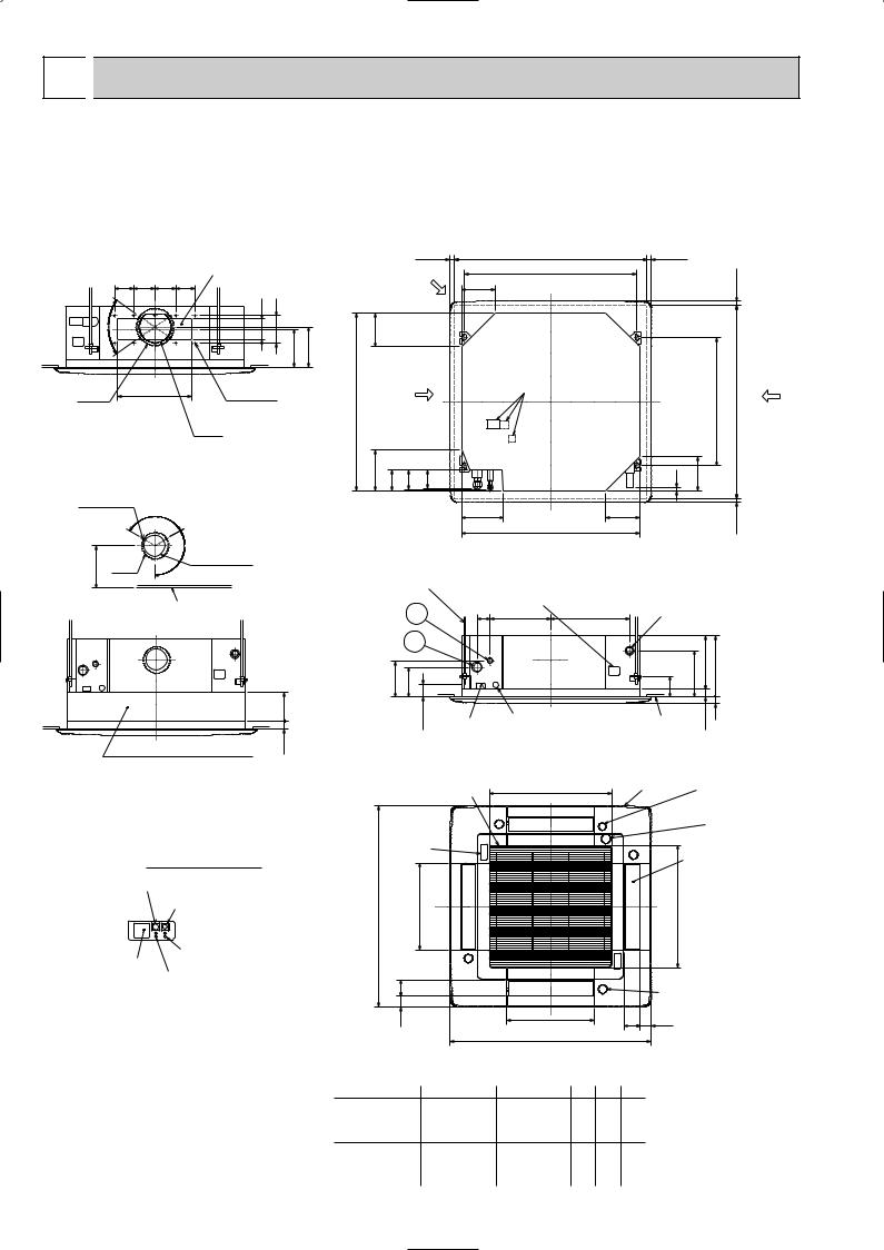
5 
 OUTLINES AND DIMENSIONS
1. INDOOR UNIT |
Unit : mm |
PLH-3AK.UK PLH-4AKS.UK PLH-5AKS.UK |
PLH-6AKS.UK |
PLH-3AK1.UK PLH-4AKS1.UK PLH-5AKS1.UK PLH-6AKS1.UK
PLH-3AKH.UK PLH-4AKHS.UK PLH-5AKHS.UK PLH-6AKHS.UK
PLH-3AKH1.UK PLH-4AKHS1.UK PLH-5AKHS1.UK PLH-6AKHS1.UK
|
|
|
|
Ceiling hole |
|
|
|
|
20~45 |
860~910 |
|
|
Branch duct hole |
Fresh air intake |
810 |
||
90 100 100 90 |
(Cut out hole) |
159 Suspension bolt pitch |
|||
|
|||||
_ |
100 |
130 |
|
|
|
70 |
|
|
159 |
|
|
|
|
|
|
||
|
|
155 |
167 |
|
|
{175 |
350 |
14 - {2.8 |
|
Burring hole
{150
Deteil drawing of fresh air intake
3 - {2.8 Burring hole
|
|
_ |
|
158 |
{125 |
120 |
{100 |
|
|||
|
(Cut out hole) |
Ceiling surface
+50 135
Branch duct hole |
Terminal block |
|
840
192 |
98 |
89 |
C |
197
840
Suspension bolt M10 |
Feeding hole |
|
||
or W3/8 |
|
|
|
|
|
|
(Drain pump) |
|
|
|
1 |
60 |
286 |
374 |
|
2 |
|
|
|
170 |
140 |
|
|
|
|
50~70 |
Power line entry |
Control wire entry |
|
Suspension bolt lower edge
20~45
|
|
20~45 |
|
|
pitch |
|
|
Ceiling hole |
Branch |
Suspension bolt |
|
|
||
|
860~910 |
duct hole |
||
605 |
|
16 |
159 |
159 |
20~45 |
|
Drain pipe VP-25connection (O.D.{32)
|
190 |
A |
B |
|
105 |
|
|||
|
|
17 |
30 |
|
Ceiling surface |
+5 |
0 |
|
|
|
|
|
||
High efficiency filter |
17 |
& Fresh air intake casement (option) |
|
A (WIRELESS PANEL)
Emergency operation switch (cooling)
Emergency operation switch (heating)
DEFROST/STAND BY lamp
Receiver
Operation lamp
|
Air intake grille |
577 |
|
Grille |
Emergency drain hole |
|
|
(Combined with hole |
|||
|
|
Air intake hole |
|
|
fed chemicals) |
|
|
|
|
|
|
|
|
M |
|
|
Drain hole |
|
|
|
|
(Combined with drain |
|
|
|
|
|
|
|
|
A |
|
|
|
pump cleaning hole ) |
|
|
M |
|
Auto vane |
|
|
|
|
|
||
|
|
|
|
|
|
950 |
411 outlet hole |
|
|
577 |
intake hole |
|
Air |
|
|
|
Air |
|
M |
|
|
|
|
|
77 |
|
M |
Vane motor |
|
|
|
|
|
||
|
51 |
411 |
77 |
51 |
|
|
Air outlet hole |
|
|||
|
|
|
|
|
|
|
|
950 |
|
|
|
Models |
1 |
2 |
A |
B |
C |
PLH-3AK |
Refrigerant pipe |
Refrigerant pipe |
|
|
|
(9.52mm dia.) |
(15.88mm dia.) |
241 |
258 |
80 |
|
PLH-3AKH |
flared connection |
flared connection |
|||
|
3/8F |
5/8F |
|
|
|
PLH-4, 5, 6AKS |
Refrigerant pipe |
Refrigerant pipe |
|
|
|
(9.52mm dia.) |
(19.05mm dia.) |
281 |
298 |
84 |
|
PLH-4, 5, 6AKHS |
flared connection |
flared connection |
|||
|
3/8F |
3/4F |
|
|
|
24
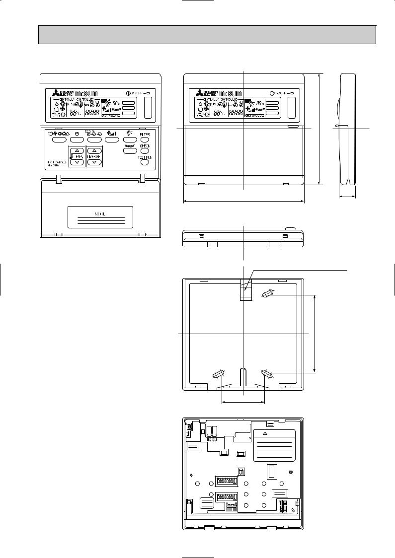
2. REMOTE CONTROLLER |
Unit : mm |
r |
r |
FILTER |
FILTER |
CHECK MODE |
CHECK MODE |
TEST RUN |
TEST RUN |
120
18
130
Rear side wiring arrangement opening.
83.5
46
CAUTION
SW18
SW17
25
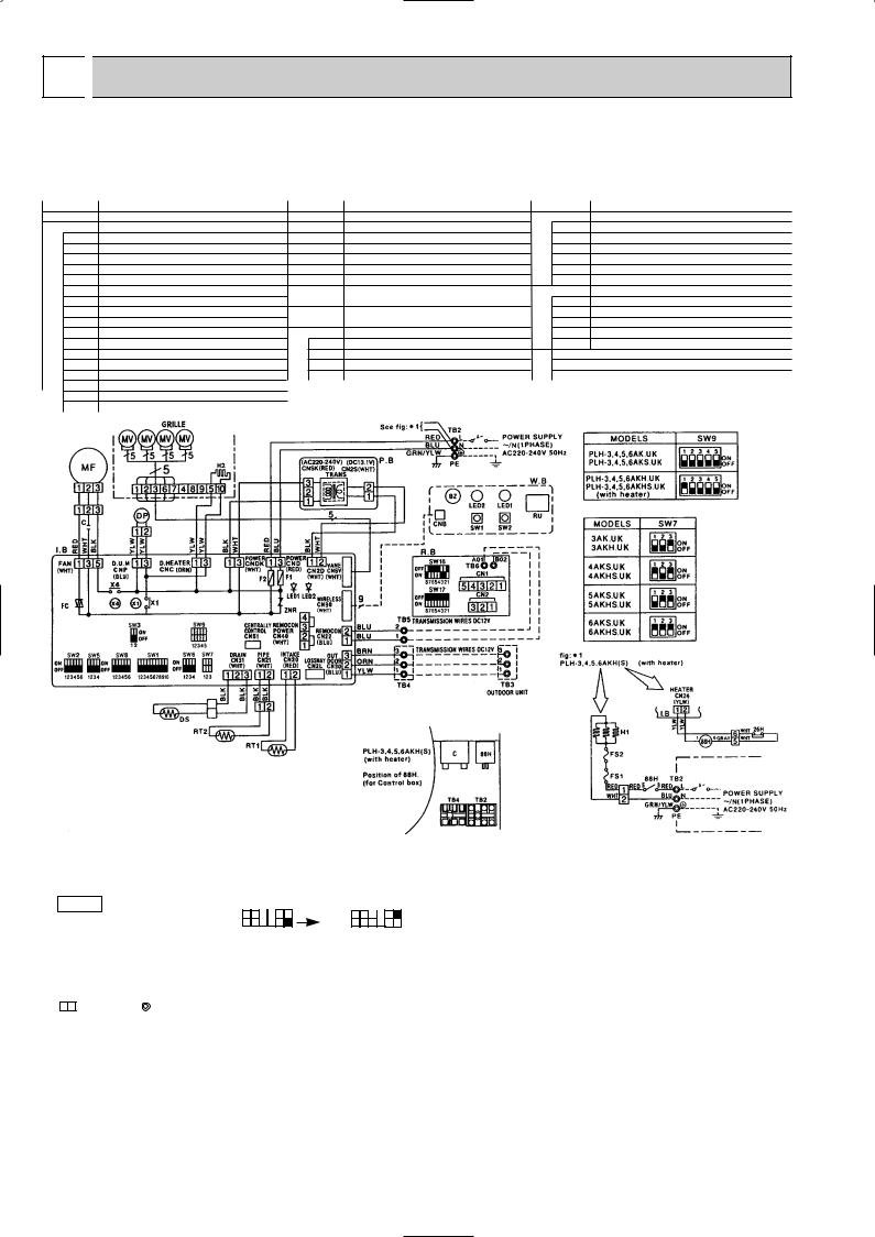
6 
 WIRING DIAGRAM
PLH-3AK.UK PLH-4AKS.UK PLH-5AKS.UK PLH-6AKS.UK PLH-3AK1.UK PLH-4AKS1.UK PLH-5AKS1.UK PLH-6AKS1.UK PLH-3AKH.UK PLH-4AKHS.UK PLH-5AKHS.UK PLH-6AKHS.UK PLH-3AKH1.UK PLH-4AKHS1.UK PLH-5AKHS1.UK PLH-6AKHS1.UK
wThe part name of symbol “I.B” is “SPCB”.
|
SYMBOL |
NAME |
SYMBOL |
NAME |
SYMBOL |
NAME |
w |
P.B |
INDOOR POWER BOARD |
C |
CAPACITOR (FAN MOTOR) |
W.B |
WIRELESS REMOTE CONTROLLER BOARD |
I.B |
INDOOR CONTROLLER BOARD |
MF |
FAN MOTOR |
RU |
RECEIVING UNIT |
|
|
CN2L |
CONNECTOR (LOSSNAY) |
MV |
VANE MOTOR |
BZ |
BUZZER |
|
CN51 |
CONNECTOR (CENTRALLY CONTROL) |
DP |
DRAIN-UP MACHINE |
LED1 |
LED (RUN INDICATOR) |
|
FC |
FAN PHASE CONTROL |
DS |
DRAIN SENSOR |
LED2 |
LED (HOT ADJUST) |
|
SW1 |
SWITCH (FUNCTION SELECTOR) |
H2 |
DEW PREVENTION HEATER |
SW1 |
SWITCH (HEATING ON / OFF) |
|
SW2 |
SWITCH (ADDRESS SELECTOR) |
TB2~TB6 |
TERMINAL BLOCK |
SW2 |
SWITCH (COOLING ON / OFF) |
|
SW3 |
SWITCH (EMERGENCY OPERATION) |
RT1 |
ROOM TEMPERATURE THERMISTOR |
HEATER |
THERMAL FUSE (72°C 16A) |
|
SW5 |
SWITCH (MODEL SELECTOR) |
|
(0: / 15k" , 25: / 5.4k" / DETECT) |
FS1 |
|
|
SW6 |
SWITCH (TWIN / TRIPLE SELECTOR) |
RT2 |
PIPE TEMPERATURE THERMISTOR / LIQUID |
FS2 |
THERMAL FUSE (104°C 16A) |
|
SW7 |
SWITCH (MODEL SELECTOR) |
|
(0: / 15k" , 25: / 5.4k" / DETECT) |
H1 |
HEATER |
|
SW8 |
SWITCH (OPTION) |
R.B |
REMOTE CONTROLLER BOARD |
26H |
HEATER THERMAL SWITCH |
|
SW9 |
SWITCH (MODEL SELECTOR) |
CN1 |
CONNECTOR (PROGRAM TIMER) |
88H |
HEATER CONTACTOR |
|
X1 |
RELAY (DRAIN PUMP) |
CN2 |
CONNECTOR (REMOTE SWITCH) |
|
|
|
X4 |
RELAY (FAN MOTOR) |
SW17 |
SWITCH (ADDRESS SELECTOR) |
|
|
|
F1, F2 |
FUSE (6.3V / 250V) |
SW18 |
SWITCH (FUNCTION SELECTOR) |
|
|
|
ZNR |
VARISTOR |
|
|
|
|
|
LED1 |
LED (DC 12V POWER) |
|
|
|
|
|
LED2 |
LED (DC 5V POWER) |
|
|
|
|
NOTES :
1.Since the indoor fan motor (MF) is connected with 230, 240V power. If 220V power is used, change the dip switch (SW8) on the indoor controller board as shown in fig : w2.
fig w2 |
SW8 |
SW8 |
Indoor fan motor (MF)for 220V. |
ON |
ON |
|
OFF 1 2 3 4 5 6 |
OFF 1 2 3 4 5 6 |
||
|
2.Since the outdoor side electric wiring may change be sure to check the outdoor unit electric wiring for servicing.
3.Indoor and outdoor connecting wires are mode with polarities, make wiring matching terminal numbers.
4.Symbols used in wiring diagram above are,
: Connector, |
: Terminal block. |
5.Emergency operation
If remote controller or microcomputer fails but there is no other trouble , emergency operation is possible by setting dip switch (SW3<I.B>) on the indoor controller board.
[Check items]
(1)Make sure that no other trouble exist the outdoor unit. Trouble with the outdoor unit prevents emergency operation.
(If any trouble exists the outdoor unit error code “P8”will be displayed on the remote controller and the trouble position will be shown on the outdoor controller board LED. See electric wiring diagram of the outdoor unit for details.)
(2)Make sure that there is no trouble with the indoor fan.
Emergency operation will be continuous run with the power ON/OFF (ON/OFF with the remote controller is not possible).
[Emergency operation procedure]
(1)Set the dip switch (SW3<I.B>) on the indoor controller board to 1 on and 2 off for cooling and 1 - 2 on for heating.
(2)Turn on are outdoor unit side circuit breaker, then indoor unit side circuit breaker.
(3)During emergency operation indoor fan runs at High speed but auto-vane does not work.
(4)Thermostat will not function. Cold air blows out for defrosting during heating thus do not operate defrosting for a long time.
(5)Emergency cooling should be limited to 10 hours maximum. (The indoor unit heat exchanger may freeze).
(6)After every emergency operation, set all dip switches (SW3<I.B>) to OFF. (7)Movement of the vanes does not work in emergency operation, therefore you
have to slowly set them manually to the appropriate position.
NOTE: If the drain water lift up mechanism is identified to be defective with the microcomputer doctor during cooling, do not use emergency operation (it causes drain overflow)
26
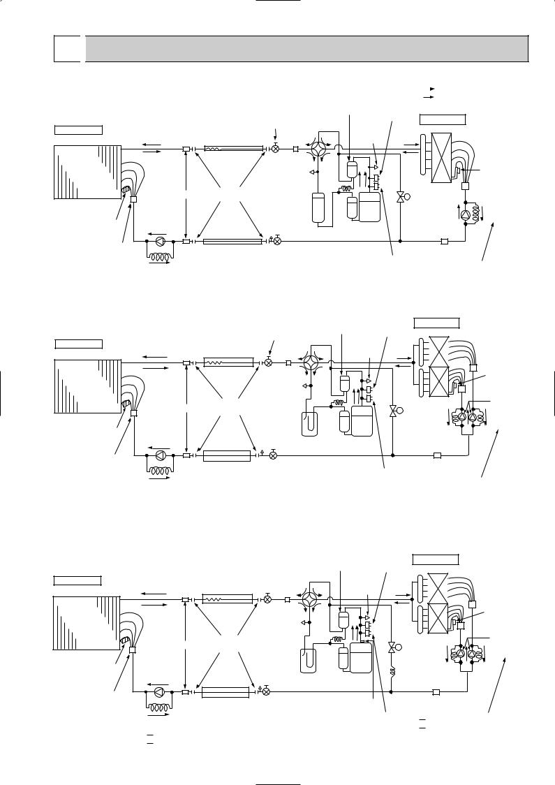
7 
 REFRIGERANT SYSTEM DIAGRAM
PLH-3AK.UK PLH-3AK1.UK / PUH-3VKA2.UK PUH-3YKA2.UK |
|
Unit : mm |
|
Refrigerant flow in cooling |
|
|
||
PLH-3AKH.UK PLH-3AKH1.UK / PUH-3VKA2.UK PUH-3YKA2.UK |
|
Refrigerant flow in heating |
|
|
|
|
|
|
|
|
|
Oil separator |
High pressure |
<R.V.coil> |
||||
|
|
|
|
|
|
|
Heating ON |
||||||
|
|
Refrigerant pipe |
|
|
|
|
|
|
control switch |
Outdoor unit |
|||
|
|
Ball valve |
|
|
|
|
Cooling OFF |
||||||
|
|
|
4-way valve |
|
|
||||||||
Indoor unit |
|
(option) |
|
|
|
Outdoor heat exchanger |
|||||||
|
15.88mm({5/8") |
|
|
|
|
|
Service |
||||||
|
|
|
Strainer |
|
|
|
|
||||||
|
|
(with heat insulator) |
|
port |
|
|
|
||||||
Indoor |
|
Flexible tube |
|
Service |
|
|
|
|
|
|
|
||
|
|
|
|
|
|
|
|
|
|
Thermistor |
|||
heat |
|
|
|
|
|
|
|
|
|
|
|||
|
|
|
|
port |
|
|
|
|
|
|
|
||
|
|
|
|
|
|
|
|
|
|
|
TH |
||
exchanger |
|
|
|
|
|
|
|
|
|
|
|
|
|
|
|
|
|
|
|
|
|
|
|
|
|
|
|
|
Strainer |
Flared |
|
|
|
|
|
|
|
Bypass |
|
||
|
|
connection |
|
|
|
|
|
|
|
|
valve |
|
|
|
|
|
|
|
|
|
|
|
|
|
|
|
|
|
|
|
|
Accumulator |
|
|
|
|
Restrictor |
Capillary |
|||
Thermistor |
Restrictor |
|
|
|
|
|
|
|
|
|
|
valve |
tube |
|
|
|
|
|
|
|
Compressor |
|
|
|
|||
valve |
|
|
|
|
|
|
|
|
|
|
|||
RT2 |
|
|
|
|
|
|
|
|
|
|
|
|
|
Distributor |
|
Refrigerant pipe |
Ball valve |
|
|
|
Protective |
|
Strainer |
|
|||
with |
|
|
|
|
|
|
|||||||
strainer |
|
(option) |
|
(with service port) |
|
high pressure |
|
|
|||||
|
Capillary |
9.52mm({3/8") |
|
|
|
|
|
switch |
PUH-3KA --- O.D.4.0 o I.D.2.4 -L1070 |
||||
|
(with heat insulator) |
|
|
|
|
|
|
|
|
|
|||
|
tube |
|
|
|
|
|
|
|
|
|
|||
|
|
|
|
|
|
|
|
|
|
|
|
|
|
O.D.4.0 o I.D.2.0 - L200 |
|
|
|
|
|
|
|
|
|
|
|
||
PLH-4AKS.UK |
PLH-4AKS1.UK |
/ PUH-4VKSA.UK |
PUH-4YKSA2.UK |
|
|||||||||
PLH-4AKHS.UK PLH-4AKHS1.UK / PUH-4VKSA.UK PUH-4YKSA2.UK |
|
||||||||||||
|
|
|
|
|
|
|
|
Oil |
|
High pressure |
Outdoor unit |
|
|
|
Refrigerant pipe |
Ball valve |
|
|
separator |
switch |
|
Outdoor heat exchanger |
|||||
|
(option) |
|
4-way valve |
|
|
|
|
|
|||||
Indoor unit |
19.05mm([ 3/4") |
|
|
Service |
|
|
|
||||||
|
Strainer |
|
|
|
|
|
|||||||
|
(with heat insulator) |
|
|
|
port |
|
|
|
|||||
Indoor |
|
Flexible tube |
|
Service |
|
|
|
|
|
|
|
Thermistor |
|
|
|
|
|
|
|
|
|
|
|
|
|||
heat |
|
|
|
|
|
|
|
|
|
|
|
TH |
|
|
|
|
|
port |
|
|
|
|
|
|
|
||
exchanger |
|
|
|
|
|
|
|
|
|
|
|
|
|
|
|
|
|
|
|
|
|
|
|
|
|
Restrictor |
|
|
Strainer |
Flared |
|
|
|
|
|
|
|
|
|
||
|
|
|
|
|
|
|
|
Bypass |
valve |
||||
|
|
connection |
|
|
|
|
|
|
|
Capillary |
|||
|
|
|
|
|
|
|
|
|
|
|
valve |
||
|
|
|
|
|
|
|
|
|
|
|
|
|
tube |
Thermistor |
|
|
|
|
|
RT2 |
|
|
Accumulator Compressor |
|
|
Restrictor valve |
|
|
|
||
Distributor |
|
|
Ball valve |
Protective |
Strainer |
with |
Refrigerant pipe |
||||
strainer |
(option) |
|
(with service port) |
high pressure |
|
|
|
switch |
(O.D. 3.2 o I.D. 2.0 - L 820) o2 |
||
Capillary |
9.52mm([ 3/8") |
|
|||
|
|
||||
tube |
(with heat insulator) |
|
|
|
|
O.D. 4.0 o I.D. 2.0 - L 250 |
|
|
|
|
|
PLH-5AKS.UK PLH-5AKS1.UK |
/ PUH-5YKSA2.UK |
|
|
||
PLH-6AKS.UK PLH-6AKS1.UK |
/ PUH-6YKSA2.UK |
|
|
||
PLH-5AKHS.UK PLH-5AKHS1.UK / PUH-5YKSA2.UK |
|
|
|
|||
PLH-6AKHS.UK PLH-6AKHS1.UK / PUH-6YKSA2.UK Oil |
|
High pressure Outdoor unit |
|
|||
|
|
|
separator |
|
||
|
Refrigerant pipe |
|
control switch Outdoor heat exchanger |
|||
Indoor unit |
(option) |
Ball valve |
4-way valve |
Service |
|
|
19.05mm([3/4") |
|
|
||||
|
(with heat insulator) Strainer |
|
port |
|
||
Indoor |
Flexible tube |
Service |
|
|
|
Thermistor |
|
|
|
|
|||
heat |
|
|
|
|
TH |
|
|
port |
|
|
|
||
exchanger |
|
|
|
|
|
|
|
|
|
|
|
Restrictor |
|
Strainer |
Flared |
|
|
|
|
|
|
|
|
Bypass |
valve |
||
|
connection |
|
|
|
Capillary tube |
|
|
|
|
|
|
valve |
|
|
|
|
|
|
|
|
Thermistor |
|
|
|
|
|
RT2 |
|
Accumulator |
Compressor |
Capillary tube |
|
Restrictor valve |
|
|
|
|
|
Distributor |
|
Ball valve |
Thermal Switch |
|
Strainer |
with |
Refrigerant pipe |
|
|||
(with service port) |
|
|
|
||
strainer |
(option) |
Protective |
|
PUH-5 (O.D. 4.0 o I.D. 2.4 - L 840) o2 |
|
|
|
||||
Capillary |
9.52mm([3/8") |
|
high pressure |
||
tube |
(with heat insulator) |
|
switch |
|
PUH-6 (O.D. 4.0 o I.D. 2.4 - L1200) o2 |
|
|
|
|||
PLH-5 O.D. 4.0 o I.D. 3.0 - L 550
PLH-6 O.D. 4.0 o I.D. 3.0 - L 380
27
 Loading...