


AIR CONDITIONERS
Model PU(H)Y-P250YGM-A
PUHY-P500YGM-A
PFD-P250VM-E
PFD-P500VM-E
DATA BOOK

|
|
PU(H)Y-P-YGM-A |
Close control |
|
PFD-P-VM-E |
|
|
|
|
CONTENTS |
|
|
|
|
1. Specifications ······················································1
1-1 Main Features ······················································1
1-2 List of Possible Combinations of Indoor and Outdoor Units ·····2
1-3 Unit Specifications ···················································3
2. Capacity Curves |
···················································4 |
|
2-1 Cooling Capacity |
···················································4 |
|
2-2 |
Cooling Input |
···················································4 |
2-3 |
SHF Curves |
···················································5 |
2-4 |
Correction by refrigerant piping length ····························6 |
|
2-5 |
Operation limit |
···················································6 |
3. Sound Levels ························································7
3-1 Noise Level ························································7
3-2 NC Curves ························································8
3-3 Fan Characteristics Curves ···········································8
4.External Dimensions ··················································10
5.Electrical Wiring Diagrams ···········································14
6.Refrigerant Circuit Diagram And Thermal Sensor ··· 18
7.System Design ·······················································20
7-1 Refrigerant Piping System ··············································20
7-2 Control Wiring ·······················································21
7-3 Types of switch settings and setting methods ················22
7-4 Sample System Connection ············································24
7-5 External input/output specifications ·······························29
8. Air Conditioning the Computer Room ·························33
8-1 Main Features of the Floor-Duct Air Conditioners ··········33
8-2 Features of air-conditioner for computer room ················33
8-3 Step-by-Step Plan for the Implementation of the Air-Conditioning ··· 34 8-4 Conditions for the Installation of Computer-Room Air Conditioners··· 35
8-5 Setting the Air conditioners ·············································36
8-6 Automatic Control of the Computer Room ······················38
9. Maintenance/Inspection ··············································39
9-1 Maintenance/Inspection Schedule ·······························39

1. Specifications
1-1.Main Features
(1) List of Models
PU(H)Y-P250YGM-A |
} Outdoor Unit |
|
PUHY-P500YGM-A |
||
|
10HP(Down flow): PFD-P250VM-E } Indoor Unit 20HP(Down flow): PFD-P500VM-E
PFD-type indoor units cannot be connected to outdoor units other than the ones specified above.
It is necessary to rewrite the S/W on the control circuit board of the outdoor unit connected to the PFD-type indoor units.
PFD-type indoor units and other types of indoor units cannot coexist in the same refrigerant system.
It is necessary to change pulley and V-belt when using it by the power supply frequency 60Hz.
For restrictions when the PFD-type indoor units are connected (related to the system), see P21.
<10HP System>
Outdoor Unit |
Indoor Unit |
PU(H)Y-P250YGM-A PFD-P250VM-E
G-50A
3 |
|
|
|
TB3 2 |
TB7 |
|
|
||
|
|
|
|
|
1
12V DC
M-NET
PAC-SC50KUA
When using a PFD-P250VM-E as an indoor unit, connect an outdoor unit PU(H)Y-P250YGM-A to each indoor unit and operate with a built-in remote control for the indoor unit.
1: Bold line indicates refrigerant piping (gas/liquid). This system consists of single refrigerant circuit.2: Indicates TB3-type transmission line that connects the indoor and outdoor units.
This system consists of single refrigerant circuit.
3: Indicates TB7-Type transmission line that allows the unit to communicate with the controller.
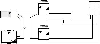
<20HP System>
 Single refrigerant circuit
Outdoor Unit |
Indoor Unit |
PUHY-P500YGM-A |
PFD-P500VM-E |
G-50A
TB7  TB3 2
TB3 2
1
12V DC
M-NET
PAC-SC50KUA
When using a PFD-P500VM-E as an indoor unit, connect an outdoor unit PUHY-P500YGM-A to each indoor unit and operate with a built-in remote control for the indoor unit.
1: Bold line indicates refrigerant piping (gas/liquid). This system consists of single refrigerant circuit.2: Indicates TB3-type transmission line that connects the indoor and outdoor units.
This system consists of single refrigerant circuit.
3: Indicates TB7-Type transmission line that allows the unit to communicate with the controller.
1
 Two refrigerant circuits
Outdoor Unit |
Indoor Unit |
||
|
|
PU(H)Y-P250YGM-A |
PFD-P500VM-E |
G-50A |
|
|
|
|
|
|
|
|
TB7 |
TB3 2 |
|
|
|
|
|
|
|
1 |
|
12V DC |
|
|
|
3 |
|
PU(H)Y-P250YGM-A |
|
|
|
|
|
TB7 |
|
TB3 |
|
M-NET |
|
|
|
PAC-SC50KUA |
|
|
|
When using a PFD-P500VM-E as an indoor unit, connect 2 PU(H)Y-P250YGM-A outdoor units to each indoor unit and operate with a built-in remote control for the indoor unit.
At factory shipment, this model of indoor unit is designed and set to accommodate a single refrigerant circuit.
Connection of two refrigerant circuits to the indoor unit requires setting change and pipe work.
1: Bold line indicates refrigerant piping (gas/liquid). This system consists of two refrigerant circuits.2: Indicates TB3-type transmission line that connects the indoor and outdoor units.
This system consists of two refrigerant circuits.
3: Indicates TB7-type transmission line that allows the unit to communicate with the controller.
1-2. List of Possible Combinations of Indoor and Outdoor Units
|
|
|
|
|
10HP system |
20HP system |
|||
Model Name |
|
|
Indoor unit |
PFD-P250VM-E |
PFD-P500VM-E |
||||
|
|
|
|
Outdoor unit |
PU(H)Y-P250YGM-A |
PU(H)Y-P250YGM-A x 2 |
|||
|
|
|
|
|
|
|
|
or PUHY-P500YGM-A |
|
|
|
|
|
|
Cooling |
|
Heating |
Cooling |
Heating |
|
|
|
|
|
|
|
|
|
|
System |
capacity |
|
kW |
28.0 |
|
31.5 |
56.0 |
63.0 |
|
System |
Power input |
|
kW |
9.3 |
|
9.1 |
18.6 |
18.2 |
|
|
|
|
|
|
|
|
|
|
|
System |
current |
|
A |
16.7/15.9/15.4 |
|
16.4/15.5/15.1 |
32.3/30.8/29.7 |
31.7/30.0/29.1 |
|
|
|
|
|
|
|
|
|||
1: Refer to the following pages for detailed specifications of each unit. |
|
|
|
||||||
2: They were measured at operation under the following conditions: |
|
|
|
||||||
<Cooling> |
Indoor:27˚CDB/19˚CWB Outdoor:35˚CDB |
|
|
|
|||||
<Heating> |
Indoor:20˚CDB |
Outdoor: 7˚CDB/6˚CWB |
|
|
|
||||
|
|
Pipe length:7.5m, Height difference:0m |
|
|
|
||||
2
1-3. Unit Specifications
(1) Outdoor Unit
Model name |
|
|
|
|
PU(H)Y-P250YGM-A (-BS) |
|
PUHY-P500YGM-A (-BS) |
|||||||||
|
|
|
|
|
|
|
|
|
connected with PFD series |
|
connected with PFD series |
|||||
|
|
|
|
|
|
|
|
|
|
|
|
|
|
|
|
|
|
|
|
|
|
|
|
|
|
Cooling |
|
Heating |
|
Cooling |
|
Heating |
|
Capacity |
|
|
|
1 |
kW |
|
28.0 |
|
|
31.5 |
|
56.0 |
|
63.0 |
||
Power source |
|
|
|
|
|
|
|
3N ~ 380/400/415V 50/60Hz |
|
|||||||
Power input |
|
|
|
|
kW |
|
6.8 |
|
|
6.6 |
|
13.6 |
|
13.2 |
||
Current |
|
|
|
|
|
|
A |
|
11.4/10.9/10.5 |
|
11.1/10.5/10.2 |
|
22.8/21.8/21.0 |
|
22.2/21.0/20.4 |
|
Fan |
|
|
Type Quantity |
|
|
|
Propeller fan x 1 |
|
Propeller fan x 2 |
|||||||
|
|
|
Airflow rate |
m3/min |
|
|
200 |
|
|
400 |
|
|||||
|
|
|
Motor output |
kW |
|
|
0.38 |
|
|
0.38 x 2 |
|
|||||
Compressor |
Type |
|
|
|
|
|
|
|
Hermetic |
|
|
|
||||
|
|
|
Motor output |
kW |
|
|
6.7 |
|
|
8.2+5.3 |
|
|||||
|
|
|
Crankcase heater |
kW |
|
|
0.045 x 1 |
|
|
0.045 x 2 |
|
|||||
Heat exchanger |
|
|
|
|
|
|
|
Salt resistant fin |
|
|||||||
Refrigerant / Lubricant |
|
|
|
|
|
|
R410A/MEL32 |
|
||||||||
External finish |
|
|
|
|
Pre-coated galvanized sheets (+ powder coating for -BS type) <MUNSEL 5Y 8/1 or similar> |
|||||||||||
External dimension H x W x D |
mm |
|
|
1,840 x 990 x 840 |
|
1,840 x 1,990 x 840 |
||||||||||
Protection |
|
High pressure protection |
|
|
|
|
|
4.15MPa |
|
|
|
|||||
devices |
|
Compressor |
|
|
|
|
|
Over current protection / Over heat protection |
|
|||||||
|
|
Fan |
|
|
|
|
|
|
|
Thermal switch |
|
|||||
|
|
Inverter |
|
|
|
|
|
|
Over current protection / Thermal protection |
|
||||||
Refrigerant |
|
|
High press. pipe |
|
ø 9.52 Flare (ø 12.7 for over 90m) |
|
ø 15.88 Flare |
|||||||||
piping diameter |
|
Low press. pipe |
|
|
ø 22.2 Brazed |
|
ø 28.58 Brazed |
|||||||||
Noise level |
|
|
|
2 |
dB(A) |
|
|
57/57 |
|
|
60/61 |
|
||||
Net weight |
|
|
|
|
kg |
|
|
233 |
|
|
455 |
|
||||
Note: |
*1. Cooling/Heating capacity indicates the maximum value at operation under the following condition. |
|
||||||||||||||
|
|
|
<Cooling> |
Indoor : 27˚CDB / 19˚CWB |
Outdoor : |
35˚CDB |
|
|
|
|||||||
|
|
|
<Heating> |
Indoor : 20˚CDB |
|
Outdoor : |
7˚CDB / 6˚CWB |
|
|
|
||||||
|
|
|
|
|
|
Pipe length : 7.5m |
|
Height difference : 0m |
|
|
|
|||||
*2. It is measured in anechoic room.
**Installation/foundation work, electrical connection work, duct work, insulation work, power source switch, and other items shall be referred to the Installation Manual.
(2)Indoor Unit
Model name |
|
|
|
PFD-P250VM-E |
|
PFD-P500VM-E |
|
|||||||
|
|
|
|
|
Cooling |
|
Heating 1 |
Cooling |
|
|
Heating |
1 |
||
System capacity |
|
kW |
28.0 |
|
31.5 |
56.0 |
|
|
63.0 |
|
||||
Power source |
|
|
|
|
|
3N~380/400/415V(50Hz), 400/415V(60Hz) |
|
|
||||||
Power input |
|
kW |
|
|
2.5 |
|
|
5.0 |
|
|
||||
Current |
|
A |
|
|
5.3/5.0/4.9 |
|
|
9.5/9.0/8.7 |
|
|
||||
|
Type x Quantity |
|
|
Sirocco fan x 1 |
|
Sirocco fan x 2 |
|
|||||||
Fan |
Airflow rate |
|
m3/min |
|
|
160 |
|
|
320 |
|
|
|||
External static pressure |
Pa |
|
|
120 |
|
|
120 |
|
|
|||||
|
|
|
|
|
|
|
||||||||
|
Motor Output |
kW |
|
|
2.2 |
|
|
4.4 |
|
|
||||
Refrigerant |
|
|
|
|
|
R410A |
|
|
|
|
||||
External finish |
|
|
|
|
|
Galvanized steel plate (with polyester coating) |
|
|
||||||
|
|
|
|
|
|
<MUNSEL 2.9GY 8.6/0.3(White) 7.2GB 3.2/5.3(Blue) or similar> |
|
|||||||
|
|
|
|
|
|
|
|
|
||||||
External dimensions H x W x D |
mm |
|
1,950 x 1,380 x 780 |
|
1,950 x 1,980 x 780 |
|
||||||||
Protection devices (Fan) |
|
|
|
|
Thermal |
switch |
|
|
|
|
||||
Refrigerant |
|
Single refrigerant |
Liquid pipe |
ø 9.52 |
Brazed (ø 12.7 for over 90m) |
Liquid pipe |
|
ø 15.88 |
Brazed |
|
||||
|
circuit |
|
Gas pipe |
|
ø 22.2 Brazed |
Gas pipe |
|
ø 28.58 |
Brazed |
|
||||
piping diameter |
|
|
|
|
|
|||||||||
|
Two refrigerant |
|
|
|
|
Liquid pipe |
ø 9.52 |
Brazed (ø 12.7 for over 90m) |
||||||
2 |
|
|
|
|
- |
|||||||||
|
|
circuit |
|
|
|
Gas pipe |
|
ø 22.2 |
Brazed |
|
||||
|
|
|
|
|
|
|
|
|
|
|||||
Refrigerant piping allowable length |
m |
|
|
150 |
|
|
150 |
|
|
|||||
Noise level |
|
dB(A) |
|
|
59 |
|
|
63 |
|
|
||||
Heat exchanger |
|
|
|
|
|
Cross fin (Aluminum plate fin and copper tube) |
|
|
||||||
Air filter |
|
|
|
|
|
PP Honeycomb fabric (washable) |
|
|
|
|
||||
Net weight |
|
kg |
|
|
380 |
|
|
520 |
|
|
||||
Note: *1. Heating can be used only by the indoor warming-up.
*2. At factory shipment, this model of indoor unit is designed and set to accommodate a single refrigerant circuit. Connection of two refrigerant circuits to the indoor unit requires setting change and pipe work.
**Installation/foundation work, electric connection work, duct work, insulation work, power source switch and other items are not specified in the specifications.
3
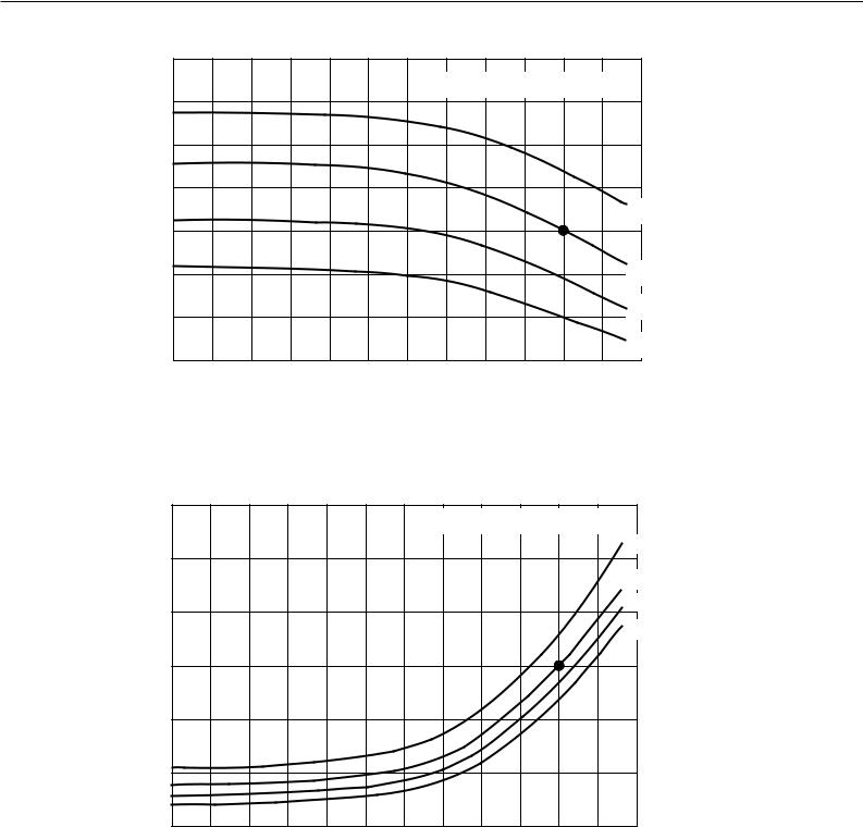
2. Capacity Curves
2-1. Cooling Capacity
Capacity correction coefficient
1.4
Indoor unit inlet temperature (˚CWB)
1.3
1.2
1.1 |
|
|
|
|
|
|
|
|
|
|
|
|
|
|
|
|
|
|
|
|
|
|
24 |
1.0 |
|
|
|
|
|
|
|
|
|
|
|
0.9 |
|
|
|
|
|
|
|
|
|
|
19 |
0.8 |
|
|
|
|
|
|
|
|
|
|
15 |
|
|
|
|
|
|
|
|
|
|
|
|
0.7 |
|
|
|
|
|
|
|
|
|
|
12 |
|
|
|
|
|
|
|
|
|
|
|
|
-15 -10 |
-5 |
0 |
5 |
10 |
15 |
20 |
25 |
30 |
35 |
40 |
45 |
Outdoor unit inlet temperature (˚CDB)
2-2. Cooling Input
Input Correction Coefficient
1.3 |
|
|
Indoor unit inlet temperature (˚CWB) |
1.2 |
24 |
|
|
|
19 |
1.1 |
15 |
|
|
|
12 |
1.0 |
|
0.9 |
|
0.8 |
|
0.7 |
|
-15 -10 |
-5 |
0 |
5 |
10 |
15 |
20 |
25 |
30 |
35 |
40 |
45 |
|
|
|
Outdoor unit inlet temperature (˚CDB) |
|
|
|
|||||
The correction curves indicate the values measured at the point where the compressor was operated at its maximum capacity.
 indicates the standard value.
4

2-3. SHF Curves
Standard Capacity Ratio
|
130% 120%110%100% |
90% |
80% |
70% |
|
|
|
|
|
||
|
1 |
|
|
|
|
|
|
|
|
|
|
|
|
|
|
|
|
|
|
Indoor Temperature 27˚CDB |
|
||
|
0.93 |
|
|
|
|
|
|
|
|
|
|
|
0.9 |
|
|
|
|
|
|
|
|
|
|
|
0.8 |
|
|
|
|
|
|
|
|
|
|
SHF |
0.7 |
|
|
|
|
|
|
|
|
|
|
|
|
|
|
|
|
|
|
|
|
|
|
|
0.6 |
|
|
|
|
|
|
|
|
|
|
|
0.5 |
|
|
|
|
|
|
|
|
|
|
|
0.4 |
|
|
|
|
|
|
|
|
|
|
|
30 |
35 |
40 |
45 |
50 |
55 |
60 |
65 |
70 |
75 |
80 |
RH (%)
Standard Capacity Ratio
130% 120%110%100% |
90% |
80% |
70% |
1 


 Indoor Temperature 24˚CDB
|
0.9 |
|
|
|
|
|
|
|
|
|
|
|
0.8 |
|
|
|
|
|
|
|
|
|
|
SHF |
0.7 |
|
|
|
|
|
|
|
|
|
|
|
|
|
|
|
|
|
|
|
|
|
|
|
0.6 |
|
|
|
|
|
|
|
|
|
|
|
0.5 |
|
|
|
|
|
|
|
|
|
|
|
0.4 |
|
|
|
|
|
|
|
|
|
|
|
30 |
35 |
40 |
45 |
50 |
55 |
60 |
65 |
70 |
75 |
80 |
RH (%)
Operation Temparature Range: Indoor : 12˚CWB~24˚CWB Outdoor: -15˚CDB~43˚CDB (RH : 30~80%)
Standard Point " " : Indoor : 27˚CDB/19˚CWB Outdoor: 35˚CDB/-
5
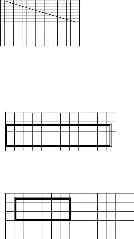
2-4. Correction by refrigerant piping length
To obtain a decrease in cooling/heating capacity due to refrigerant piping extension, multiply by the capacity correction factor based on the refrigerant piping equivalent length in the table below.
Capacity correction coefficient
1
0.9
0.8
0.7
0 |
20 |
40 |
60 |
80 |
100 |
120 |
140 |
160 |
180 |
Piping equivalent length (m)
• How to obtain piping equivalent length
Equivalent length = (Actual piping length to the farthest indoor unit) + (0.50 number of bent on the piping)m
2-5. Operation limit
• Cooling
Indoor temperature (˚CWB)
30
25
20
15
12
10
-15 -10 -5 |
0 |
5 |
10 |
15 |
20 |
25 |
30 |
35 |
40 |
45 |
|
|
Outdoor temperature (˚CDB) |
|
|
|
|
||||
*The height between the Outdoor PU(H)Y-P-YGM-A and Indoor could make the running temperature range narrow. For details refer to P20, 7-1 Refrigerant Piping System.
•Heating
Indoor temperature (˚CDB)
30
25
20
15
10
5 |
|
|
|
|
|
|
|
|
|
|
|
|
-20 -15 -10 |
-5 |
0 |
5 |
10 |
15 |
20 |
25 |
30 |
35 |
40 |
45 |
50 |
Outdoor temperature (˚CWB)
6
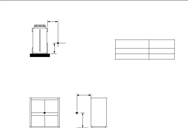
3. Sound Levels
3-1. Noise Level
(1) Outdoor Unit
1m
Measured point
1m
(2) Indoor Unit
1m
Measured |
|
point |
1m |
|
Series
Noise Level
(dB [Type A])
PU(H)Y-P250YGM-A 57
PUHY-P500YGM-A 60/61
(50Hz/60Hz)
Series |
Noise Level |
|
(dB [Type A]) |
||
|
||
|
|
|
PFD-P250VM-E |
59 |
|
|
|
|
PFD-P500VM-E |
63 |
|
|
|
7
3-2. NC Curves
PU(H)Y-P250YGM-A |
(External static |
|||||||
|
|
|
|
|
pressure 0Pa) |
|||
63Hz |
125Hz |
250Hz |
500Hz |
1000Hz |
2000Hz |
4000Hz |
8000Hz |
dB(A) |
62.5 |
58.5 |
55.5 |
53 |
49.5 |
49 |
49 |
43 |
57 |
|
|
|
|
|
|
|
|
|
|
90 |
|
|
|
|
|
|
|
Pa |
80 |
|
|
|
|
|
|
|
20 |
|
|
|
|
|
|
|
|
|
|
|
|
|
|
|
|
|
0dB = |
70 |
|
|
|
|
|
|
NC-70 |
(dB) |
|
|
|
|
|
|
|
|
LEVEL |
60 |
|
|
|
|
|
|
NC-60 |
|
|
|
|
|
|
|
|
|
PRESSURE |
50 |
|
|
|
|
|
|
NC-50 |
40 |
|
|
|
|
|
|
NC-40 |
|
|
|
|
|
|
|
|
|
|
BAND |
30 |
|
|
|
|
|
|
NC-30 |
OCTAVE |
20 |
|
|
|
|
|
|
NC-20 |
Approximate minimum |
|
|
|
|
||||
audible limit on |
|
|
|
|
|
|
||
|
|
|
|
|
|
|
||
|
continuous noise |
|
|
|
|
|
||
|
10 |
|
|
|
|
|
|
|
|
63 |
125 |
250 |
500 |
1000 |
2000 |
4000 |
8000 |
|
|
OCTAVE BAND CENTER FREQUENCIES (Hz) |
|
|||||
PFD-P250VM-E |
(External static |
|
|||||||
|
pressure 120Pa) |
||||||||
|
|
|
|
|
|||||
|
|
|
|
|
|
|
|
|
|
63Hz |
125Hz |
250Hz |
500Hz |
1000Hz |
2000Hz |
4000Hz |
8000Hz |
|
dB(A) |
70.6 |
62.7 |
60.5 |
56.1 |
54.8 |
45.7 |
39.7 |
32.9 |
|
59 |
|
|
|
|
|
|
|
|
|
|
|
90 |
|
|
|
|
|
|
|
|
Pa |
80 |
|
|
|
|
|
|
|
|
20 |
|
|
|
|
|
|
|
|
|
|
|
|
|
|
|
|
|
|
|
= |
|
|
|
|
|
|
|
|
|
0dB |
70 |
|
|
|
|
|
|
|
NC-70 |
|
|
|
|
|
|
|
|
||
(dB) |
|
|
|
|
|
|
|
|
|
LEVEL |
60 |
|
|
|
|
|
|
|
NC-60 |
|
|
|
|
|
|
|
|
||
|
|
|
|
|
|
|
|
|
|
PRESSURE |
50 |
|
|
|
|
|
|
|
NC-50 |
|
|
|
|
|
|
|
|
||
40 |
|
|
|
|
|
|
|
NC-40 |
|
|
|
|
|
|
|
|
|
||
|
|
|
|
|
|
|
|
|
|
BAND |
30 |
|
|
|
|
|
|
|
NC-30 |
|
|
|
|
|
|
|
|
||
OCTAVE |
20 |
Approximate minimum |
|
|
|
|
NC-20 |
||
|
audible limit on |
|
|
|
|
|
|||
|
|
|
|
|
|
|
|||
|
|
|
|
|
|
|
|
||
|
10 |
continuous noise |
|
|
|
|
|
||
|
|
|
|
|
|
|
|
|
|
|
63Hz |
125Hz |
250Hz |
500Hz |
1000Hz |
2000Hz |
4000Hz |
8000Hz |
|
OCTAVE BAND CENTER FREQUENCIES (Hz)
PUHY-P500YGM-A |
(External static |
|
|||||||
pressure 0Pa) |
|
||||||||
|
|
|
|
|
|
||||
|
|
|
|
|
|
|
|
|
|
|
63Hz |
125Hz |
250Hz |
500Hz |
1000Hz |
2000Hz |
4000Hz |
8000Hz |
dB(A) |
50Hz |
67 |
61.5 |
60.5 |
58 |
53.5 |
50.5 |
48 |
43 |
60 |
|
|
|
|
|
|
|
|
|
|
60Hz |
68 |
65 |
60.5 |
59 |
54 |
51.5 |
49 |
43.5 |
61 |
|
|
|
|
|
|
|
|
|
|
|
|
|
|
|
|
50Hz |
|
60Hz |
|
90 |
|
|
|
|
|
|
|
Pa |
80 |
|
|
|
|
|
|
|
20 |
|
|
|
|
|
|
|
|
|
|
|
|
|
|
|
|
|
0dB = |
70 |
|
|
|
|
|
|
NC-70 |
(dB) |
|
|
|
|
|
|
|
|
LEVEL |
60 |
|
|
|
|
|
|
NC-60 |
|
|
|
|
|
|
|
|
|
PRESSURE |
50 |
|
|
|
|
|
|
NC-50 |
40 |
|
|
|
|
|
|
NC-40 |
|
|
|
|
|
|
|
|
|
|
BAND |
30 |
|
|
|
|
|
|
NC-30 |
OCTAVE |
20 |
|
|
|
|
|
|
NC-20 |
Approximate minimum |
|
|
|
|
||||
audible limit on |
|
|
|
|
|
|
||
|
|
|
|
|
|
|
||
|
continuous noise |
|
|
|
|
|
||
|
10 |
|
|
|
|
|
|
|
|
63 |
125 |
250 |
500 |
1000 |
2000 |
4000 |
8000 |
|
|
OCTAVE BAND CENTER FREQUENCIES (Hz) |
|
|||||
PFD-P500VM-E |
(External static |
|
|||||||
|
pressure 120Pa) |
||||||||
|
|
|
|
|
|||||
|
|
|
|
|
|
|
|
|
|
63Hz |
125Hz |
250Hz |
500Hz |
1000Hz |
2000Hz |
4000Hz |
8000Hz |
|
dB(A) |
82.8 |
70.5 |
65.6 |
57,0 |
55.1 |
51.1 |
44.7 |
37.9 |
|
63 |
|
|
|
|
|
|
|
|
|
|
|
90 |
|
|
|
|
|
|
|
|
Pa |
80 |
|
|
|
|
|
|
|
|
20 |
|
|
|
|
|
|
|
|
|
|
|
|
|
|
|
|
|
|
|
= |
|
|
|
|
|
|
|
|
|
0dB |
70 |
|
|
|
|
|
|
|
NC-70 |
|
|
|
|
|
|
|
|
||
(dB) |
|
|
|
|
|
|
|
|
|
LEVEL |
60 |
|
|
|
|
|
|
|
NC-60 |
|
|
|
|
|
|
|
|
||
|
|
|
|
|
|
|
|
|
|
PRESSURE |
50 |
|
|
|
|
|
|
|
NC-50 |
|
|
|
|
|
|
|
|
||
40 |
|
|
|
|
|
|
NC-40 |
||
|
|
|
|
|
|
|
|||
|
|
|
|
|
|
|
|
|
|
BAND |
30 |
|
|
|
|
|
|
|
NC-30 |
OCTAVE |
20 |
Approximate minimum |
|
|
|
|
NC-20 |
||
|
audible limit on |
|
|
|
|
|
|||
|
|
|
|
|
|
|
|||
|
|
|
|
|
|
|
|
||
|
10 |
continuous noise |
|
|
|
|
|
||
|
|
|
|
|
|
|
|
|
|
|
63Hz |
125Hz |
250Hz |
500Hz |
1000Hz |
2000Hz |
4000Hz |
8000Hz |
|
|
|
|
OCTAVE BAND CENTER FREQUENCIES (Hz) |
|
|||||
8

3-3. Fan Characteristics Curves
|
|
PFD-P250VM-E |
: 50/60Hz, standard |
|
||||
|
|
|
|
|
|
|||
|
1000 |
|
|
|
|
|
|
|
|
900 |
|
|
|
Output 3.7kW |
|
|
|
|
|
|
|
|
Fan rotation speed |
|||
|
|
|
|
|
|
|
||
|
800 |
|
1 |
|
|
|
1200rpm |
|
|
|
|
|
|
|
|
|
|
(Pa) |
|
|
2 |
|
|
|
|
|
700 |
3 |
|
|
|
|
|
|
|
|
|
|
|
|
|
|
||
pressure |
|
|
|
|
|
|
1100rpm |
|
600 |
4 |
|
|
|
|
|
||
|
|
|
|
|
|
|
||
500 |
5 |
|
|
|
|
|
1000rpm |
|
6 |
|
|
|
|
|
|||
static |
|
|
|
|
|
|
|
|
400 |
7 |
|
|
|
|
900rpm |
|
|
Total |
|
|
|
|
|
|
||
|
8 |
|
|
|
|
|
||
300 |
|
|
800rpm |
|
|
|
||
9 |
|
|
|
|
|
|||
|
200 |
|
Internal |
|
|
|
|
|
|
|
|
resistance |
|
|
|
|
|
|
100 |
|
|
|
|
|
|
|
|
0 |
136 |
|
|
|
|
|
184 |
|
|
|
|
|
|
|
||
|
130 |
|
140 |
150 |
160 |
170 |
180 |
190 |
Air volume (m3/min)
|
|
|
50Hz |
|
|
60Hz |
|
|
|
|
|
|
|
|
|
|
|
No. |
Rotational |
Motor pulley |
Fan pulley |
V-belte |
Motor pulley |
Fan pulley |
V-belte |
|
speed (rpm) |
||||||||
|
|
|
|
|
|
|
||
1 |
1170 |
ø 160-B-2-28 |
ø 200-B-2-42 |
B48 |
ø 165-B-2-28 |
ø 250-B-2-42 |
B52 |
|
2 |
1140 |
ø 165-B-2-28 |
ø 212-B-2-42 |
B49 |
ø 180-B-2-28 |
ø 280-B-2-42 |
B56 |
|
3 |
1080 |
ø 165-B-2-28 |
ø 224-B-2-42 |
B50 |
ø 170-B-2-28 |
ø 280-B-2-42 |
B54 |
|
4 |
1040 |
ø 165-B-2-28 |
ø 236-B-2-42 |
B51 |
ø 165-B-2-28 |
ø 280-B-2-42 |
B54 |
|
5 |
973 |
ø 165-B-2-28 |
ø 250-B-2-42 |
B52 |
ø 165-B-2-28 |
ø 300-B-2-42 |
B55 |
|
6 |
930 |
ø 170-B-2-28 |
ø 280-B-2-42 |
B54 |
ø 160-B-2-28 |
ø 315-B-2-42 |
B56 |
|
7 |
845 |
ø 160-B-2-28 |
ø 280-B-2-42 |
B53 |
ø 170-B-2-28 |
ø 355-B-2-42 |
B59 |
|
8 |
797 |
ø 170-B-2-28 |
ø 315-B-2-42 |
B56 |
ø 160-B-2-28 |
ø 355-B-2-42 |
B59 |
|
9 |
748 |
ø 160-B-2-28 |
ø 315-B-2-42 |
B56 |
- |
- |
- |
Pulley and V-belt is procured on site.
|
|
PFD-P500VM-E |
: 50/60Hz, standard |
|
||
|
800 |
|
|
|
||
|
|
|
|
|
|
|
(Pa) |
700 |
3 |
Output 5.5kW |
Fan rotation speed |
||
pressure |
|
|
||||
600 |
|
|
||||
4 |
|
|
|
|
||
|
|
1100rpm |
|
|
||
|
5 |
|
|
|
||
500 |
|
|
|
|
||
6 |
|
|
|
|
||
static |
|
|
|
1000rpm |
|
|
400 |
|
|
|
|
||
7 |
|
|
|
|
||
Total |
|
|
|
|
|
|
300 |
8 |
|
|
|
|
|
|
|
|
|
|
||
|
|
|
|
|
|
|
|
200 |
9 |
|
|
900rpm |
|
|
|
800rpm |
|
|
|
|
|
|
|
|
|
|
|
|
100 |
Internal resistance |
|
|
|
|
|
|
|
Standardrd |
|
||
|
|
|
|
|
||
|
0 |
272 |
|
318 |
345 |
|
|
|
|
|
|||
|
250 |
270 |
290 |
310 |
330 |
350 |
Air volume (m3/min)
|
|
|
50Hz |
|
|
60Hz |
|
|
|
|
|
|
|
|
|
|
|
No. |
Rotational |
Motor pulley |
Fan pulley |
V-belte |
Motor pulley |
Fan pulley |
V-belte |
|
speed (rpm) |
||||||||
|
|
|
|
|
|
|
||
3 |
1135 |
ø 180-B-2-38 |
ø 236-B-2-42 |
B51 |
ø 160-B-2-38 |
ø 250-B-2-42 |
B50 |
|
4 |
1070 |
ø 180-B-2-38 |
ø 250-B-2-42 |
B51 |
ø 180-B-2-38 |
ø 300-B-2-42 |
B55 |
|
5 |
1015 |
ø 170-B-2-38 |
ø 250-B-2-42 |
B51 |
ø 160-B-2-38 |
ø 280-B-2-42 |
B52 |
|
6 |
978 |
ø 160-B-2-38 |
ø 250-B-2-42 |
B50 |
ø 160-B-2-38 |
ø 300-B-2-42 |
B54 |
|
7 |
905 |
ø 170-B-2-38 |
ø 280-B-2-42 |
B53 |
ø 160-B-2-38 |
ø 315-B-2-42 |
B55 |
|
8 |
850 |
ø 180-B-2-38 |
ø 315-B-2-42 |
B56 |
ø 170-B-2-38 |
ø 355-B-2-42 |
B58 |
|
9 |
803 |
ø 170-B-2-38 |
ø 315-B-2-42 |
B55 |
ø 160-B-2-38 |
ø 355-B-2-42 |
B58 |
Pulley and V-belt is procured on site.
9

494
ø 27 Knockout hole  Y <Bottom hole for
control wiring>
 Y
Y
Conn. pipe(Gas) |
553 |
|
ø 22.2 <Brazed> |
||
|
136 |
80 |
166 |
20 |
57
Conn. pipe(Liquid) ø 9.52 <Flare>
10
65 |
160 |
|
|
70 |
|
768 |
80 |
ø 62 Knockout hole |
|||
|
|
||||
|
|
<Hole for power supply> |
|||
|
Knockout hole |
|
Changeable to ø 27,ø 33 by using |
||
|
|
attached conduit mounting plate <Accessory> |
|||
|
<Bottom piping hole> |
|
|||
|
|
|
|||
|
Cross section X – X |
Air outlet |
|||
|
|
||||
|
|
ø 53 |
|
|
|
|
|
|
|
Air |
|
|
12 |
5 |
Air |
inlet |
|
|
|
|
|
||
Cross section Y – Y |
inlet |
|
|||
|
|
||||
2X2-14X20 0val hole |
45 |
900(mounting pitch) |
(Mounting hole) |
990 |
|
|
|
Top view |
Knockout hole
<Accessories> |
|
|
• Refrigerant (Gas) conn. pipe...... |
1 pc. |
|
(Already installed on the unit) |
|
|
• Packing for conn. pipe................ |
|
1 pc. |
(Attached near the ball valve) |
|
|
• Conduit mounting plate |
|
|
ø 33, ø 27.............................. |
1 pc.Each |
|
• Tapping screw M4...................... |
|
2 pcs. |
Note1.Use the opening at the bottom of the unit when running the power supply line from the front or from the side of the unit.
Note2.Please refer to the next page for information regarding necessary spacing around the unit and foundation work.
|
|
|
ø 27 Knockout hole |
Service panel |
|
|
|
|
||
|
|
|
|
|
|
|
|
|
||
|
135 |
|
<Left side hole for |
Refrig. service |
|
|
|
|
||
|
|
control wiring> |
|
|
|
|
||||
|
80 |
40 |
valve (Liquid) |
67 160 |
|
|
||||
|
|
|
<Flare> |
|
|
|
||||
|
|
|
|
|
X |
|
|
|
|
|
|
|
|
|
|
|
|
|
|
|
|
|
|
|
134 100 |
|
|
44 |
|
|
|
|
90 |
|
|
280 |
235 |
150 |
|
|
|
|
|
10 |
|
|
Knockout hole |
|
100 |
|
83 |
Knockout hole |
|
|
|
|
|
|
|
|
|||||
37 117 |
117 |
37 |
|
|
<Front piping |
|
||||
|
|
|
<Left piping hole> |
Refrig. service |
67 |
207 |
hole> |
207 67 |
||
|
|
|
|
|
valve(Gas) |
|
||||
|
Left side view |
|
|
|
|
|
|
Front view |
|
|
|
|
|
|
<Flange> |
|
|
|
|
||
|
16 |
|
840 |
845(mounting pitch) |
877 |
|
16 |
|
45
265
1575 1840
 X
X
11 78
A-P250YGM-PU(H)Y
mm : Unit
Dimensions External .4
Y-P250YGM-A, PUHY-P500YGM-A, PFD-P250VM-E, PFD-P500VM-E DATA BOOK")
|
|
|
494 |
|
1000 |
|
|
|
|
|
|
16 |
|
|
|
|
|
|
|
|
|
|
|
|
|
|
|
|
|
|
|
Y |
|
Y |
|
|
|
|
|
pitch) |
|
|
|
|
|
|
|
|
|
|
|
|
|
|
|
|
|
|
|
Y |
control wiring> |
553 |
|
|
|
840 |
845(mounting |
877 |
|
|
|
|
|
|
Y |
|
|
|
|
|
|
|
|
Knockout hole |
|
|
|
|
ø 27 Knockout hole |
|
|
|
|
|
|
|
|
|
|
|
|
<Bottom hole for |
|
|
|
|
|
|
|
||
<Bottom piping hole> |
|
|
|
|
|
|
|
|
|
|
|||
|
|
|
|
|
|
|
|
|
|
|
|
||
145 |
80 |
|
162 |
|
20 |
|
|
|
|
|
|
|
|
|
57 |
65 |
160 |
|
70 |
ø 62 Knockout hole |
3X2-14X20 Oval hole |
45 |
950(mounting pitch) |
950(mounting pitch) |
45 |
16 |
|
|
|
|
768 |
|
80 |
<Hole for power supply> |
|
|
|||||
|
|
|
|
Changeable to ø 46,ø 53 by using |
(Mounting hole) |
|
|
1990 |
|
|
|
||
Conn. pipe(Gas) |
|
|
|
|
|
|
|
|
|
||||
Conn. pipe(Liquid) |
|
|
attached conduit mounting plate <Accessory> |
|
|
|
|
|
|
||||
ø 28.58<Brazed> |
Cross section X – X |
|
|
|
Top view |
|
|
|
|||||
ø 15.88<Flare> |
|
|
|
|
|
|
|||||||
|
|
|
|
|
|
|
|
||||||
11
ø 53
12 5
Cross section Y – Y
<Accessories>
•Refrigerant (Gas) conn. pipe....1 pc. (Already installed on the unit)
•Packing for conn. pipe......1 pc. (Attached near the ball valve)
•Conduit mounting plate ø 53, ø 46......1 pc.Each
•Tapping screw M4...2 pcs.
Note1.Use the opening at the bottom of the unit when running the power supply line from the front or from the side of the unit.
Note2.Please refer to the next page for information regarding necessary spacing around the unit and foundation work.
Air inlet
10 89
37 115
Air outlet |
|
|
|
|
|
|
|
|
|
|
|
|
|
|
|
|
|
|
265 |
|
Air |
|
|
|
|
|
|
|
|
|
inlet |
|
|
|
|
|
|
|
|
|
|
|
Knockout hole |
|
|
|
|
1840 |
|
|
|
|
|
|
|
|
1575 |
||
|
ø 27 Knockout hole |
Service panel |
|
|
|
|
|||
|
|
|
|
|
|
||||
|
<Left side hole for |
|
|
|
|
|
|||
135 |
|
|
|
|
|
|
|
||
control wiring> |
Refrig. service |
|
|
|
|
|
|||
80 |
40 |
|
|
|
|
|
|
||
|
valve (Liquid) |
67 160 |
|
|
|
||||
|
|
|
|
|
|
||||
|
|
|
<Flare> |
|
|
|
|
X |
|
|
|
|
|
X |
|
|
|
|
|
|
134 100 |
|
|
44 |
|
|
|
|
|
|
280 |
235 |
150 |
|
|
|
|
78 |
|
|
Knockout hole |
|
100 |
|
83 |
Knockout hole |
|
11 |
|
|
|
|
|
|
|||||
115 |
37 <Left piping hole> |
Refrig. service |
68 |
205 |
<Front piping hole> |
205 |
68 |
||
|
|
|
|
||||||
Left side view |
|
|
valve(Gas) |
|
|
Front view |
|
|
|
|
|
|
<Flange> |
|
|
|
|
|
|
A-P500YGM-PUHY
mm : Unit
 Loading...