


PLK-E1010

MITSUBISHI
Industrial Sewing Machine
TECHNICAL MANUAL
MECHANICAL VERSION
Electronic Pattern Sewing Machine
Model PLK-E1010
A180E494P01
From the library of Superior Sewing Machine & Supply LLC • www.supsew.com
FOR YOUR SAFETY !
If you operate the sewing machine first time, please make sure to read the following
instructions for your safet y and proper oper ation.
In this technical manual, the notice CAUTION is mentioned at some paragraph to attract your
attention for the safety. Please keep it in mind whenever you work with the sewing machine.
CAUTION is used as the notice to warn a possible danger to cause a wound.
This technical manual explains the instructions how to operate and maintain the
sewing machine.
All information in this technical manual ar e subj ect to change without notice.
MITSUBISHI ELECTRIC CORPORATION
Reprinting the parts or all of this technical manual is not allowed without permission.
has all the copy rights on this technical manual.
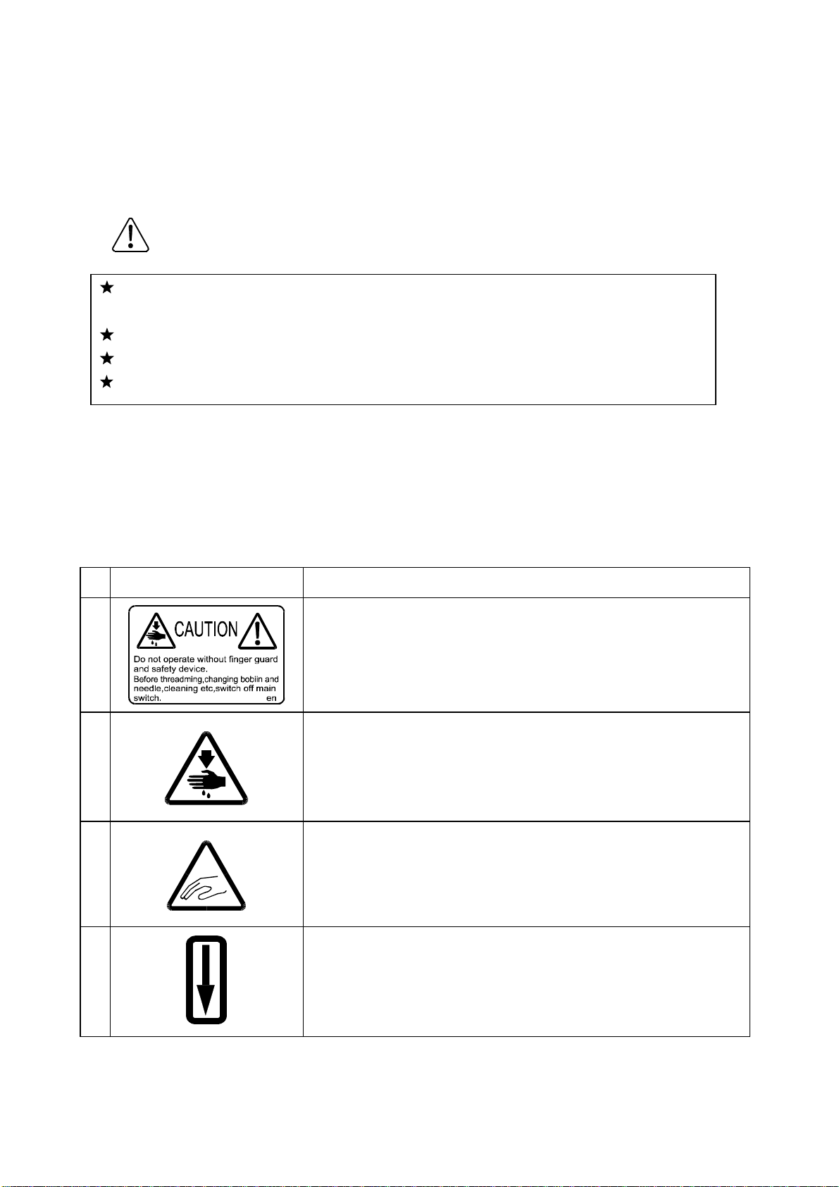
Explanations for the wa r ni ng signs
No Warning sign
1
Caution for sewing machine operation:
Warning to operate the sewing machine without safety
guards and to prohibit doing any operation except sewing
while the power is turned ON.
Meanings of warning sign
2
3
4
Caution for a wound on the fingers:
Warning to a possible danger to cause a wound on the
fingers under the specif ied oper at ion.
Caution for the fing er s to be caught in the machine:
Warning to a possible danger to be caught the fingers in the
machine under the specified operation.
Direction of pulley rotation:
Indicating the proper rotating direction of the sewing
machine pulley.

From the library of Superior Sewing Machine & Supply LLC • www.supsew.com
ENVIRONMENT STANDARD
For avoiding the sewing machine from the troubles, please do not operate the sewing
machine under the following conditions.
Caution
(1)
(a) During operating : The atmosphere temperature should not exceeded more 35ºC
(b) During transportation : The atmosphere temperature should not exceeded more
(2)
(a) In the atmosphere filled with dust or cor r osive g as.
(b) In the atmosphere filled with f lam mable or explosive gas.
(3)
(a) In the place where the power fluctuation exceeds more or less 10 % of the fixed
(b) In the place where the power source can not supply enough voltage to keep the
(4)
Temperature and humidity
(95ºF) or less 5ºC(41ºF).
55ºC (131ºF) or less -10ºC (18ºF) .
The relative humidity in the atmosphere should not exceeded more 85% or less 45%.
Atmosphere for the machine oper at ion
Power source voltage
power voltage.
motor running.
Power source voltage
(a) In the place where the power fluctuation exceeds more or less 10 % of the fixed
power voltage.
(b) In the place where the power source can not supply enough voltage to keep the
motor running.
(5)
Noise
(a) In the place near a high frequency tr ansm it t er or a high frequency welder.
(b) In the place filled with strong electrom agnetic radiation or magnetic field.

·
·
·
·
·
From the library of Superior Sewing Machine & Supply LLC • www.supsew.com
CONTENTS
1. STRUCTURE OF THE MACHINE ······································································
2. SPECIFICATION ··································································································
3. INSTALLATION ···································································································
1
2
3
3-1. Preparation of the table ··················································································
3-2. Preparation for the steel stand ········································································ 3
3-3. Installation of the motor ··················································································
3-4. Installation of the control box ·········································································· 3
3-5. Connection of the operation panel ·································································· 3
3-6. Installation of the power switch ······································································· 4
3-7. Connection of the foot switch ········································································· 4
3-8. Installation of the oil pan ················································································· 5
3-9. Installation of the sewing machine head ·························································
3-10. Putting across the V-belt ··············································································· 6
3-11. Connection of the electric cables ··································································
3-12. Installation of the belt cover ········································································· 8
3-13. Installation of the thread stand ······································································ 9
3-14. Functioning the work holder pedal ································································ 9
4. LUBRICATION ····································································································
3
3
5
7
10
5. PROPER OPERATION ······················································································
5-1. Loading the system software to the control box ············································· 11
5-2. Installation of the needle ················································································· 11
5-3 Threading the upper thread ············································································· 12
5-4. Winding the bobbin thread ············································································· 12
5-5. Setting the bobbin ··························································································· 14
5-6. Setting the bobbin case ·················································································· 14
6. PROPER SEWING ·······························································································
6-1. Operation of the halt switch ············································································
6-2. The sewing operation ····················································································· 16
6-3. Adjustment of the thread tension ···································································· 17
11
15
15

·
·
·
·
·
·
·
·
·
From the library of Superior Sewing Machine & Supply LLC • www.supsew.com
7. ST ANDARD ADJUSTMENT ···············································································
7-1. Adjustment of the needle bar position ····························································· 19
7-2. Adjustment of the position between the needle and the shuttle hook ·············· 20
7-3. Adjustment of the clearance between the shuttle hook and the needle ··········
7-4. Adjustment of the clearance between the driver and the needle ····················· 21
7-5. Adjustment of the thread guide ······································································· 22
7-6. Adjustment of the presser foot ········································································ 22
7-6-1. Adjustment of the presser foot position ················································
7-6-2. Adjustment of the presser foot lift during the sewing ····························
7-6-3. Adjustment of the presser foot timing ··················································· 25
7-7. Adjustment of the wiper ·················································································· 26
7-8. Adjustment of the bobbin winder ····································································· 27
7-9. Adjustment of the work holder ········································································
7-10. Adjustment of the trimmer cam follower ························································ 28
7-11. Adjustment of the position for movable knife point ········································ 28
7-12. Adjustment of the fixed knife position ···························································
7-13. Adjustment of the thread take up spring stroke ············································
7-14. Adjustment of the thread take up spring tension ··········································· 29
7-15. Adjustment of the thread tail after the trimming ············································
7-16. Cancellation of the trimming function ···························································· 30
7-17. Adjustment of the upper thread tension ························································ 30
7-18. Adjustment of the synchronizer ····································································· 31
7-19. Adjustment of the mechanical home position ················································ 32
7-19-1. Shifting the mechanical home position X direction ······························ 32
7-19-2. Shifting the mechanical home position Y direction ······························ 33
7-20. Adjustment of the X-Y contact pressure ······················································· 34
19
21
22
25
27
29
29
30
7-21. Adjustment of the X-Y timing belt tension ····················································· 34
7-21-1. Adjustment of the X timing belt tension ··············································· 34
7-21-1. Adjustment of the Y timing belt tension ··············································· 35
7-22. Adjustment of the V belt tension ··································································· 35
8. MAINTENANCE ·································································································
8-1. Cleaning ·········································································································
8-2. Disposing of oil waste ····················································································· 36
9. BAD SEWING CONDITION & ITS CAUSE AND REMEDY ···························
APPENDIX ··················································································································
Ref.1. Table cut out drawin g ···················································································· 41
Ref.2. Table & stand assembly ················································································ 41
Ref.3. St and components drawin gs ········································································
36
36
37
40
42
From the library of Superior Sewing Machine & Supply LLC • www.supsew.com
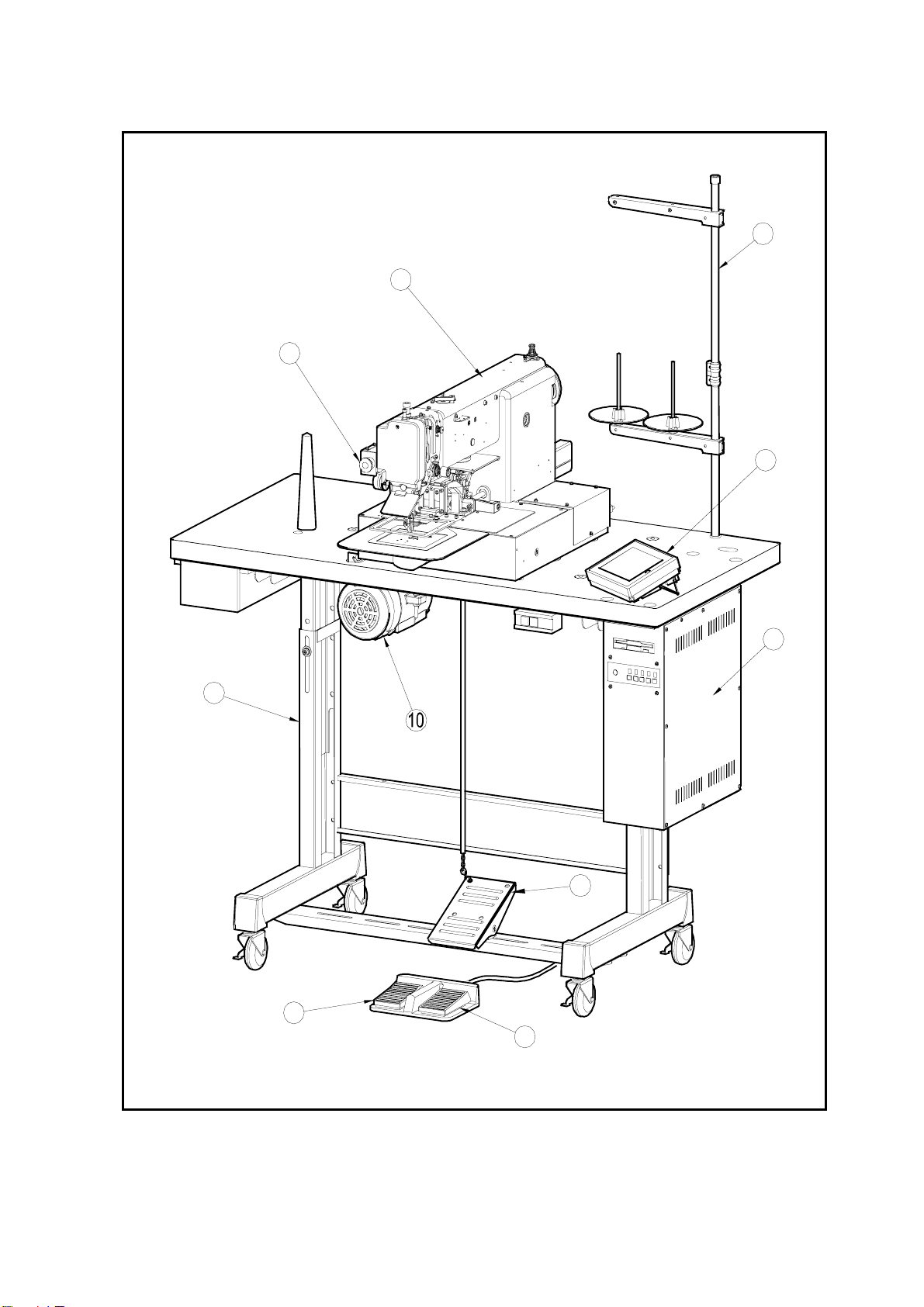
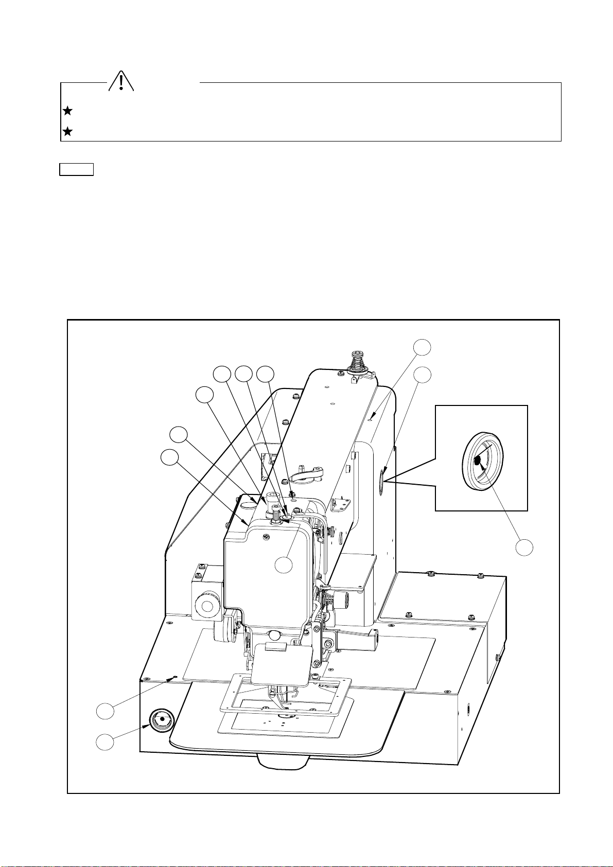
1. STRUCTURE OF THE SEWING MACHINE
PLK-E1010 electronic pattern sewing machine is constructed with the following main parts.
1
5
2
3
4
9
8
7
6
1
Sewing machine head 2Thread stand
6
Work holder foot switch 7 Start foot switch
*Limi-servo motor
3Operation Panel
8Work holder pedal 9Steel stand
1
4Control Unit
5Halt switch

From the library of Superior Sewing Machine & Supply LLC • www.supsew.com
2. SPECIFICATION
(1) Specification of mechanism
Sewing area : X-Direction (left/ right) Y-Direction (fore/backward)
: 100mm 100mm
Maximum sewing speed : 2500 rpm
Sewing speed : 10 steps variable from 200 to 2500 rpm
Stitch length : 0.1 to 12.7 mm
(Adjustable from 0.1mm to 12.7mm by 0.1mm resolution)
Stitch type : Single needle lock stitch
Needle bar stroke : 41.2 mm
Thread take up lever stroke : 68 mm
Class of needle : DP X 17 # 16 (the standard specification)
Wiper system : Back to forward wiping system (the standard specification)
Left to right wiping system (t he optional specification)
*1
Presser foot lift
Presser foot stroke
Work holder lift
: 15 mm (18mm max.)
*2
: Variable from 4mm to 10mm ( 4m m is standard)
*2
: 25 mm
Hook : Large size shuttle hook
Bobbin case : With non racing spring
Bobbin : Large size aluminum bobbin
Thread trimmer system Horizontal engagement with fixed knife and movable knife
Lubrication system :
Manual oiling and replenishment with the oil braids from the oil
tanks
Lubrication oil : White machining oil
X-Y drive system : Stepping motor and timing belt drive
Intermittent or continuous feeding
Machine dimension : 1,200mm(W) x 565mm(L) x 1,220mm(H)
Weight : TOTAL 143Kg
Type of controller : PLK-E-CU-20
Steel stand : T-shape steel stand for the standing or the sitting operation
(2) Specification of main motor
Type of motor : XL- 554- 20
2

Cautio
From the library of Superior Sewing Machine & Supply LLC • www.supsew.com
3. INSTALLATION
The machine should be installed by the specialists who have enough experience for the
sewing machine installations.
All the necessary electric wiring should be done by electric engineers who are qualified for the
electric wiring.
If any damage or fault is found on the machine at the installation, please do not operate until it
is repaired.
Please do not operate the sewing machine with excessive modifications from the standard
specification
3-1 Preparation of the table
If the table is not MITSUBISHI original, the thickness of the table is required to have 40mm
more.
And please refer to the cut out t able dr awing for your own preparation.
The cut out drawing is shown on the last page of this technical manual as APPENDIX drawing.
3-2 Preparation for the steel stand
If the steel stand is not MITSUBISHI original, please refer to the assembling drawing for your
own preparation.
The assembling drawing is shown on the last page of t his t echnical manual as Ref.1 to Ref.3.
If the steel stand is MITSUBISHI original, please assemble the steel stand with the assembling
instructions enclosed in the packing.
3-3 Installation of the motor
If the motor is purchased without assembling to the table, the motor has to be installed
underneath the table.
Please install the motor with the instructions explained in the paragraph [Installation of the
Motor] on the other [CONTROL UNI T] technical manual.
3-4 Installation of the control box
If the control box is purchased without assembling to the table, the control box has to be
installed underneath the table.
Please install the control box with the instruction in the paragraph [Installation of the control
n
box] on the other
CONTROL UNIT technical manual.
3-5 Connection of the operation panel
Please connect the operation panel with the instructions of Operation Panel manual enclosed in
the packing.
3
From the library of Superior Sewing Machine & Supply LLC • www.supsew.com
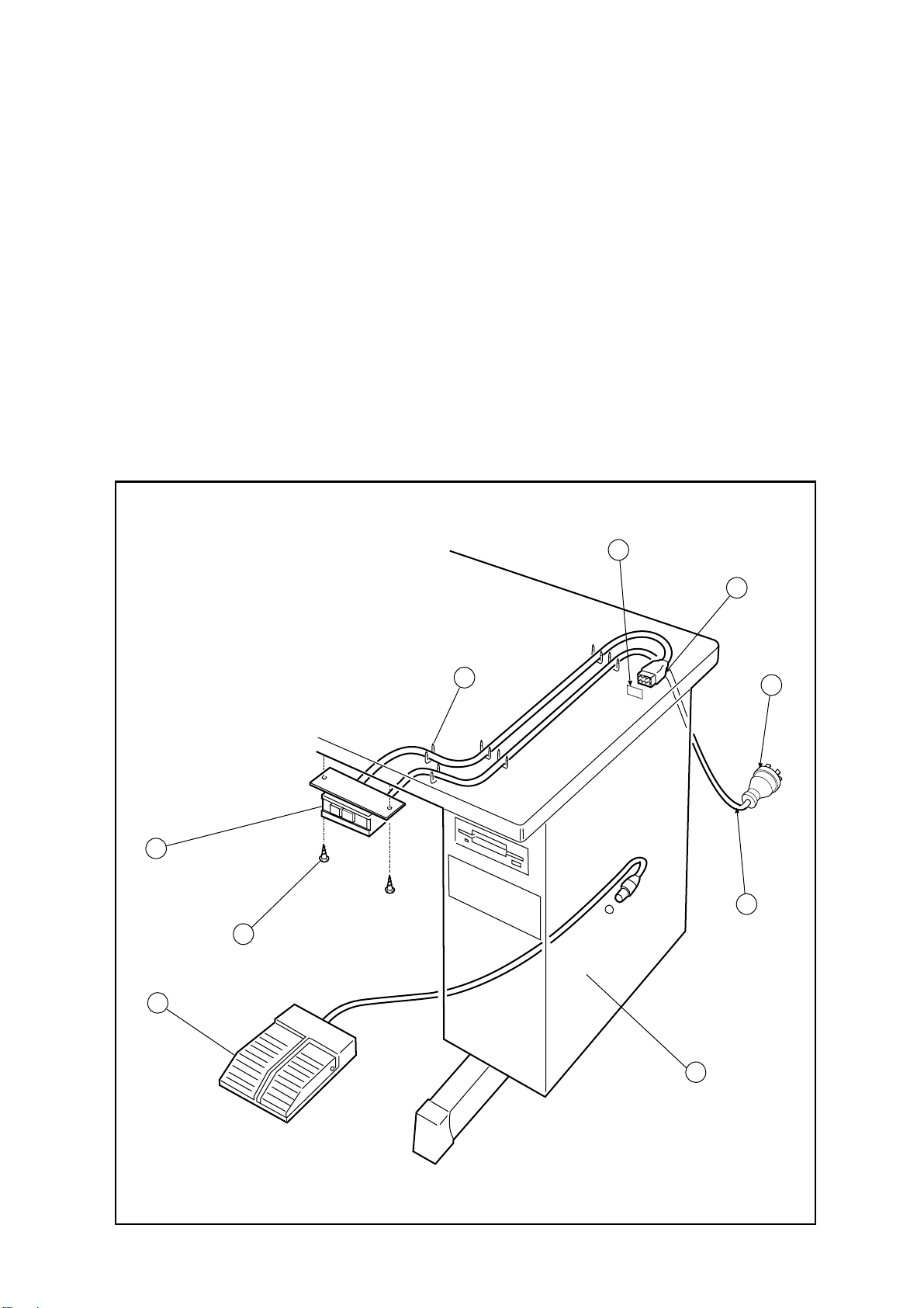
3-6 Installation of the power switch
If the power switch is purchased without assembling to the table, the power switch has to be
attached with the following procedure.
(1) Mount the power switch (NO.1) with the wood screw (NO.2) underneath the table as shown
on the figure.
(2) Fix the electric cords with the staples (NO.3) underneath the table.
(3) Hook up the connector (NO.4) of the power switch (NO.1) to the connector (NO.5) of the
control box (NO.9).
(4) Attach the power plug (NO.7) to another end of the power switch cord (NO.6).
3-7 Connection of the foot switch
Connect the foot switch (NO.8) t o t he cont rol box (NO.9)
The foot switch is enclosed in the accessory box.
5
4
3
1
2
7
6
8
4
9
From the library of Superior Sewing Machine & Supply LLC • www.supsew.com
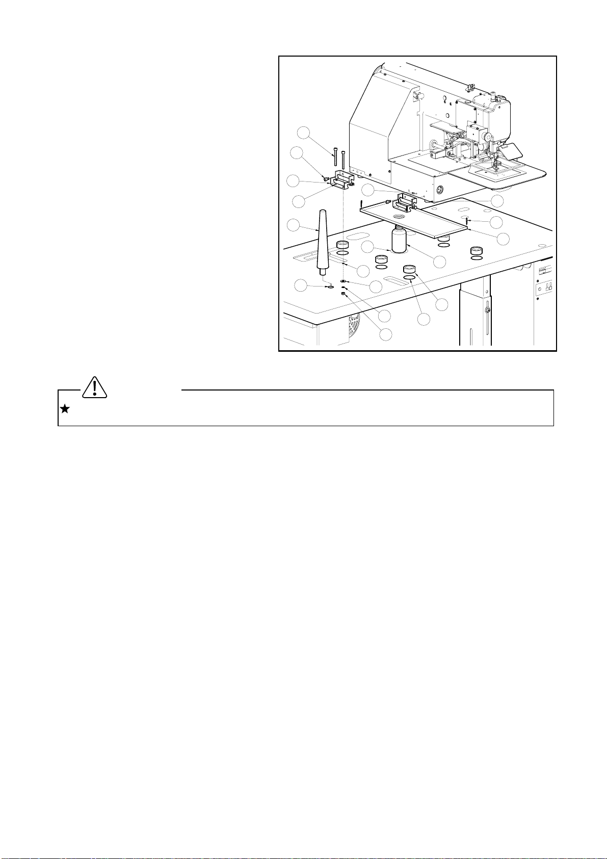
3-8 Installation of the oil pan
(1) Assemble the oil pan (NO.1) and
oil bottle (NO.2), which are
enclosed in the accessory box.
(2) I nsert the oil bottle (NO.2) into the
tabletop cut-out hole (NO.3), which
14
11
has much shorter distance from
the bottle center to the fr ont.
(3) Install the oil pan (NO.1) parallel
with the table front edge.
(4) Fix the oil pan (NO.1) at its four
corners on the table top with four
staples (NO.4) en-closed in the
accessory box.
18
9
13
19
12
10
8
4
3
2
15
6
16
17
7
1
3-9 Installation of the sewing machine head
For the safety, please make sure t o carry the sewing machine head by more than two people.
(1) Make sure to hold the machine table with the caster stopper.
(2) Fit t he rubber cushion pads (NO.6) into the each hole (NO.7) on the tabletop. The rubber
Caution
cushion pads (NO.6) are enclosed in the accessory box.
(3) Put the sewing machine head on the table top and set the each leg (NO.8) to the each
rubber cushion pad (NO.6)
(4) Att ach two hinges (NO.9) temporarily, make the setting screw (NO.11) fastening with the
thread holes (NO.10) light, on the left side surface of the machine bed with the hexagonal
socket head set screws (NO.11).
(5) At this time, take notice that the E-shaped snap ring on the front side hinge must be come
to the backside, and E-shaped snap ring on the backside hinge must be come to the front.
(6) These parts are all enclosed in the accessory box.
(7) Fit the screw holes (NO.13) of the hinges (NO.9) to the bolt setting holes (NO.12) on the
table top then, pass the bolt (NO.14) through these holes and fasten the bolt (NO.14) to fix
the hinges (NO.9) with the flat washers (NO.15), the spring washers (NO.16) and the nuts
(NO.17).
(8) Fasten firmly hexagonal socket head set screws (NO.11), which set the hinges (NO.9)
temporarily at above procedure (4) then, fix the hinges (NO.9) perfect ly.
(9) Insert the headrest (NO.18) into t he hole ( NO .19) on the tabletop.
5
Cautio
From the library of Superior Sewing Machine & Supply LLC • www.supsew.com
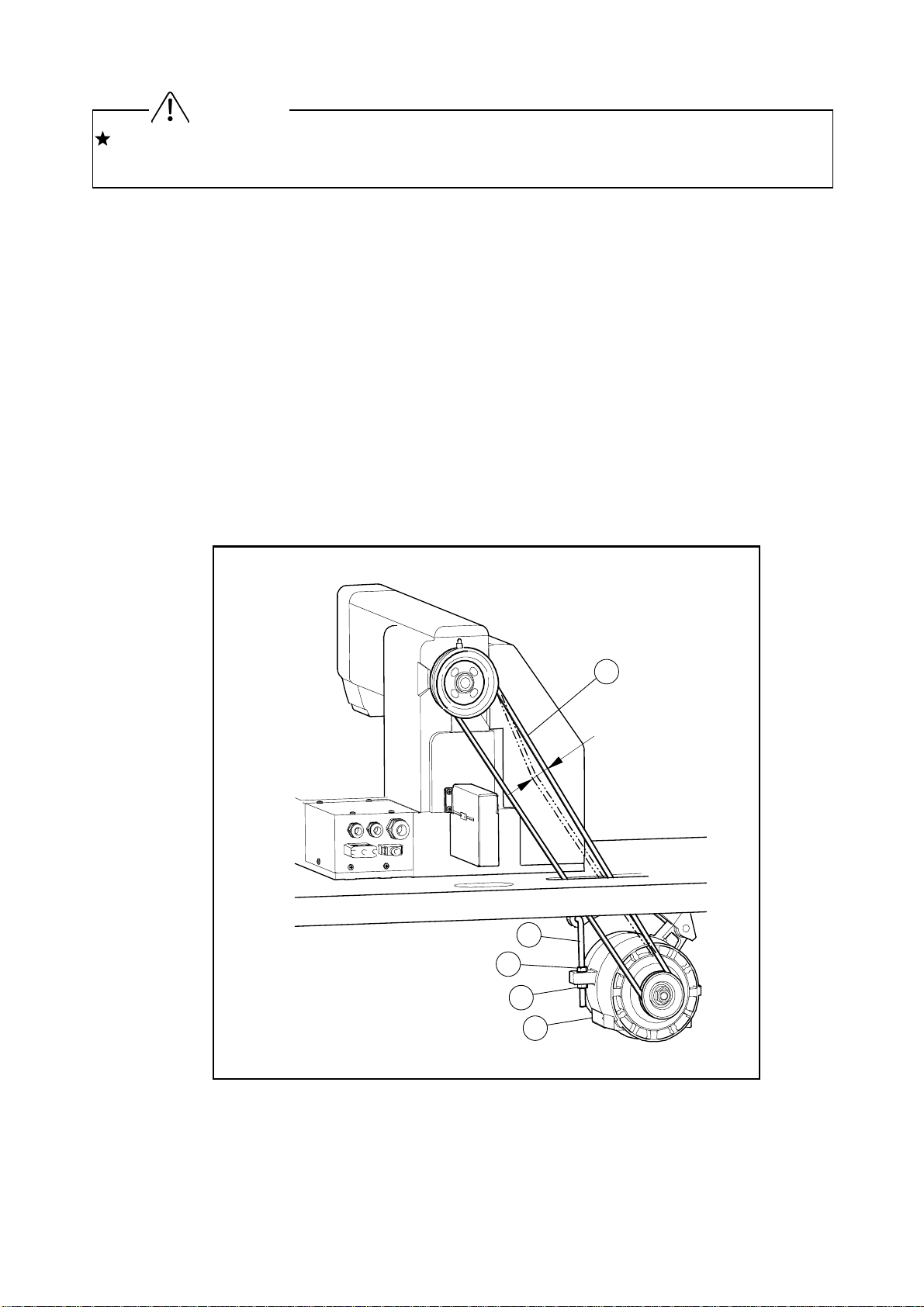
3-10 Putting across the V-belt
For the safety, when tilt or raise the sewing machine head, please make sure to hold the
sewing machine head with both hands by two people at least.
(1) Tilt the sewing machine head to the left, and hold it with the head r est.
(2) Put the V-belt (NO.4) across the sewing machine pulley and the motor pulley with passing it
through the slit on the tabletop.
(3) Raise the tilted sewing machine head to the original position.
(4) Push the center portion of V-belt by the f inger with the presser of about 1Kg.
If the V-belt tension is proper , it should be yielded about 10 mm.
If the V-belt tension is not pr oper, please adjust it as follows.
(5) Loosen two nut (No.2) on the motor .position adjust bolt (No.1).
(6) Fix the motor (No.5) position with putting the tension to the V belt by its weight and firstly,
tighten the upper nut (No.2) t hen secondly, t ighten the lower nut (No.2).
Please make sure to fasten t he nut s ( NO . 5) firmly after the adjust m ent .
(7) Put the motor pulley cover on the motor with the set screws.
n
10
4
mm
1
2
6
3
5
From the library of Superior Sewing Machine & Supply LLC • www.supsew.com
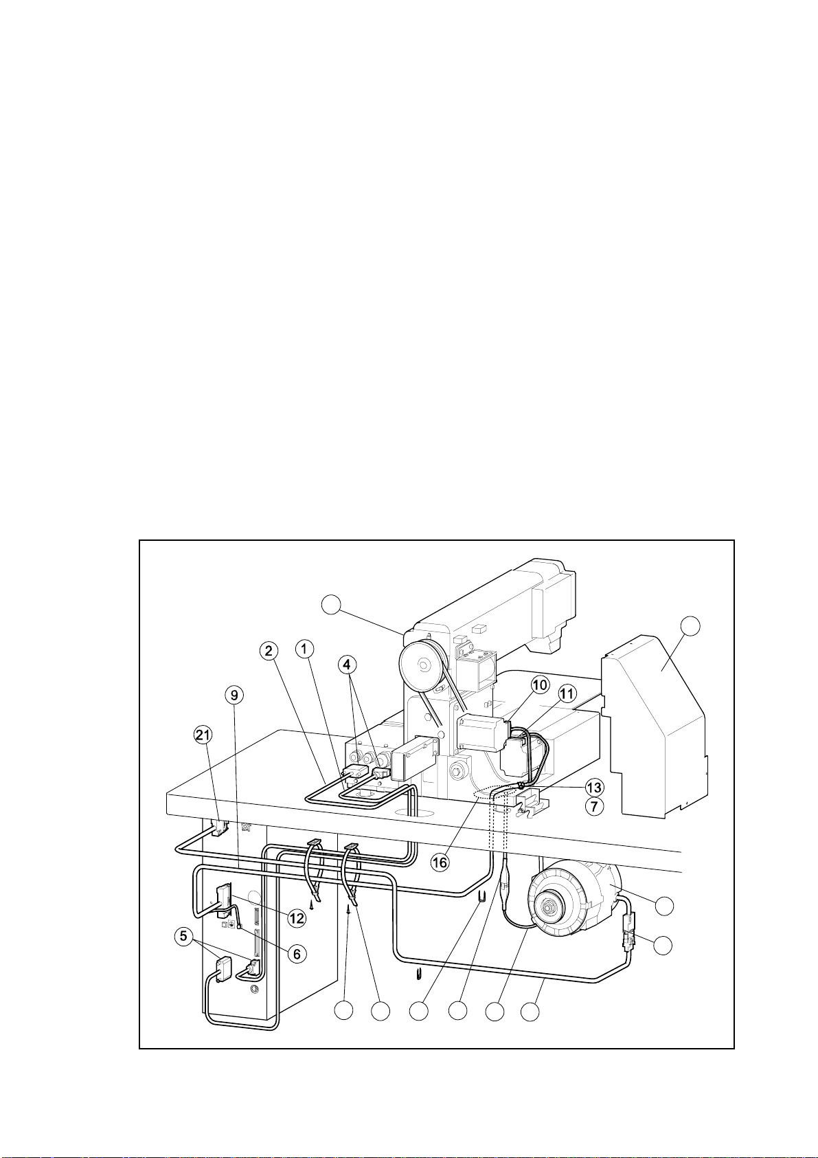
3-11 Connection of the electric cables
(1) Connect t he white color cable (NO.1) and the black color cable (NO.2) across the printed
circuit board unit connectors (NO.4) on the sewing machine head (NO.3) rear face and the
connectors (NO.5) on the control box. T hese cables ar e enclosed in t he accessor y box.
(2) Remove the stepping motor cover (NO.8) f r om sewing machine head ( NO . 3).
(3) Pass upward the cable (NO.9) which is attached the two connectors at the end, through the
cut-out hole (NO.16) on the table top then, connect it to the X-stepping motor connector
(No.11) and to the Y-stepping motor connector (No.10). At this time, fix this cable with the
nylon clip (NO.13) and setscrew (No.7) which are provided on the sewing machine head.
And also, connect the other end of the cable (NO.9) to the connector (NO.12) on the control
box. The cable (NO.9) is enclosed in the accessory box.
(4) Pass downward the another cable (NO.15) which is extended from the sewing machine
head through the cut-out hole (NO.16) on the table top then, connect it to the cable (NO.18)
extended from the motor (NO . 17)
(5) Connect the last cable (NO. 19) to the other extended cable (NO.20) from the motor then,
hook up the other end of the cable ( NO.19) to the connector (NO.21) on the control box.
(6) Attach the tow binder (NO.22) underneath the table with the wood screws (NO.23) then,
bundle and fix all the connected cables with the binders (NO.22) and the staples (NO.23).
The binders (NO.22), the wood screws (NO.23) and the stables (NO.24) are enclosed in
the accessory box.
3
8
17
20
23
15
2422
18
19
7
From the library of Superior Sewing Machine & Supply LLC • www.supsew.com
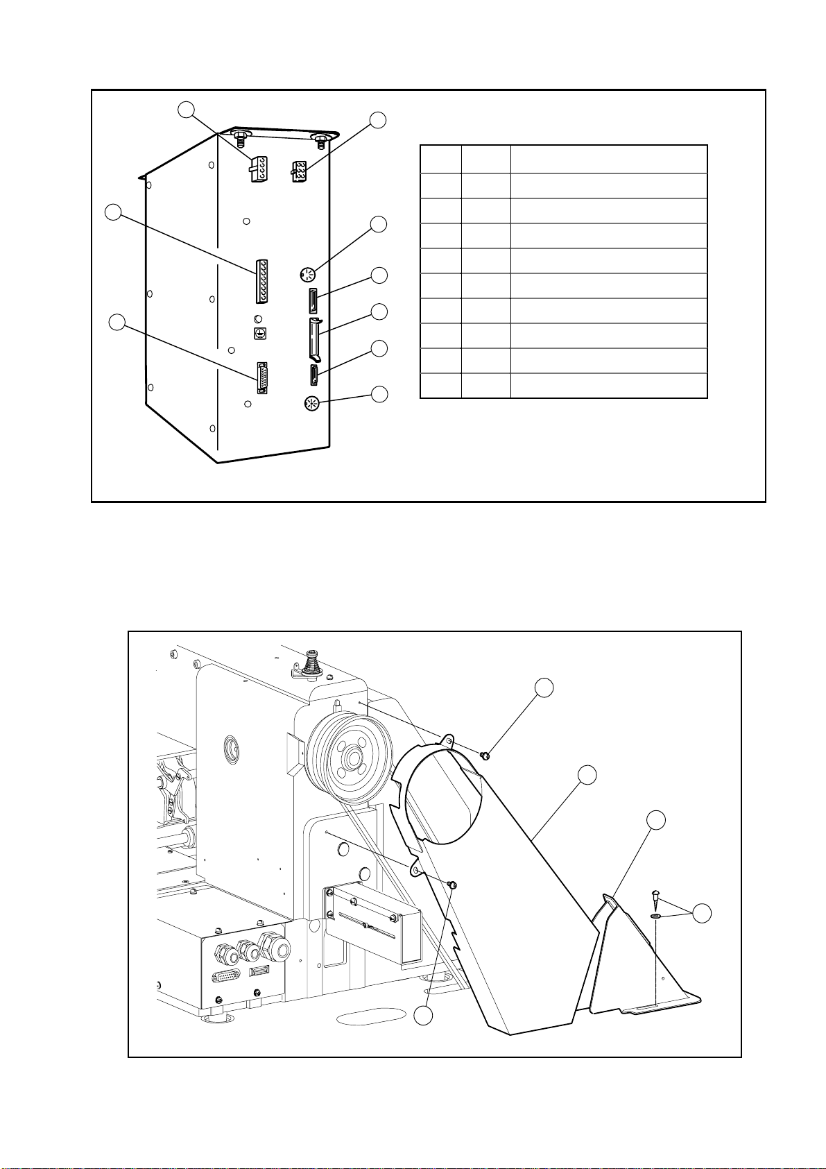
< Back side view of the Control box >
3
4
1
2
Fig Con Connect with
1 A Main motor cable
2 B Power supply cable
5
6
7
8
9
3 C Stepping motor cable
4 D Solenoid output cable
5 E RS-232C (optional use)
6 F O per at ion panel cable
7 G Extension I/O cable
8 H Input signal cable
9 I Foot switch cable
3-12 Installation of the belt cover
Put the large belt cover (NO.2) on t he sewing machine head with the set scr ews (NO. 1 & 4)
and small belt cover (NO.3) on the table top with the set screws (NO. 5)
All the necessary parts are enclosed in the accessory box.
4
2
3
5
1
8
From the library of Superior Sewing Machine & Supply LLC • www.supsew.com
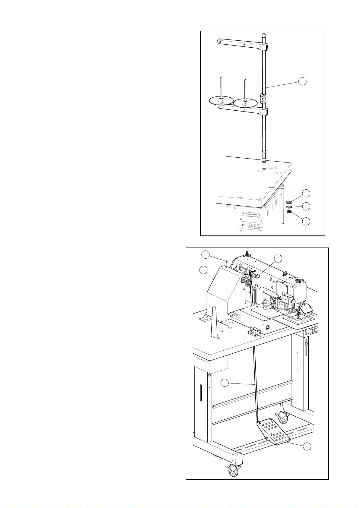
3-13 Installation of the thread stand
(1) Assemble the thread stand with the
instructions enclosed in the packing.
(2) Fit the thread stand (NO.1) in the thread
stand hole on the tabletop.
(3) Fix the thread stand (NO.1) firmly from the
rear side of the table with tightening the nut
(NO.4) and the washers (NO.2, 3).
1
2
3
4
3-14 Functioning the work holder pedal
(1) Connect the chain (NO.1) across the
lever (NO.2) located at the left side of the
sewing machine head and the work
holder pedal mounted on the steel stand
bottom beam. The chain (NO.1) is
enclosed in the accessory box.
(2) Put the stepping motor cover (NO.4) back
on the sewing machine head with the
screw (NO.5) after the chain (NO.1)
connection.
5
2
4
1
9
3
Cautio
From the library of Superior Sewing Machine & Supply LLC • www.supsew.com
4. LUBRICATION
Please make sure to turn power switch OFF befor e oiling.
Please make sure to put some oil before starting the operation of the brand new machine or
NOTE Please use high quality white machining oil.
4-1 Filling the oil tank
Pour the oil through the oil hole (NO.1) to the oil tank (NO.2) on the machine arm. Move the
work holder by hand to the right end then, machine bed. Please fill with the oil over level mark
(NO.6) of the oil tank.
4-2 Oiling
Put some oil to red marked oil holes (NO . 7 ~ 13).
n
8
9
10
11
12
7
13
1
2
6
4
5
10
From the library of Superior Sewing Machine & Supply LLC • www.supsew.com
5. PROPER OPERATION
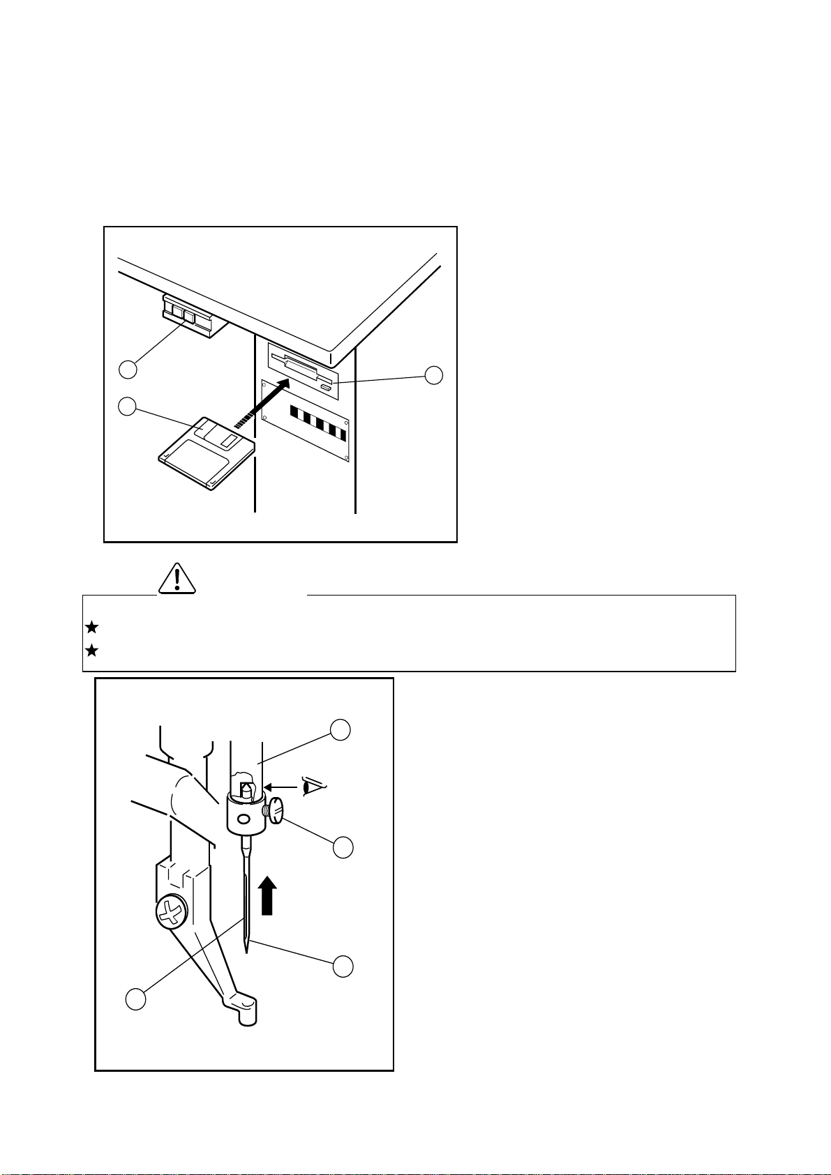
5-1 Loading the system software to the control box.
When the brand new machine is operated first time or when the control box is adjusted for the
repairing, the system software has to be loaded t o the control box.
For this loading, please take the following procedure.
(1) Insert the system floppy disc printed
[ F1 ] (NO.2) into the disc drive (NO.3)
of the control box.
O
F
F
O
N
(2) The system floppy discs are enclosed
in the accessory box.
1
(3) Turn the power switch (NO.1) ON.
3
(4) Load the system software with
2
5-2 Installation of the needle
Please make sure to turn the power switch OFF bef or e installing or replacing the needle.
Please pay attention for the fingers not to be wounded by the needlepoint.
Caution
(1) Loosen the needle set screw (NO.1) then,
insert the new needle (NO.2) until the
3
needle head is reached the end of the
following the instructions [Loading the
system software] on the technical
manual [
(5)
After loading the system software,
CONTROL UNIT].
keep the system floppy disks with in
care.
hole of the needle bar (NO.3).
(2) Fasten the setting screw (NO.1) with
facing the needle groove (NO.4) to the
1
front.
2
4
11
 Loading...