


Mitsubishi Electronics PU12EK, PU18EK, PU18EK1, PU24EK, PU24EK1 User Manual
...SPLIT-TYPE, AIR CONDITIONERS
No. OC247
REVISED EDITION-E
TECHNICAL & SERVICE MANUAL
<Outdoor unit> Models PU12EK
PU18EK PU18EK1
PU24EK PU24EK1 PU24EK2 PU24EK3 PU30EK PU30EK1 PU30EK2 PU30EK3 PU36EK PU36EK1 PU36EK2 PU36EK3 PU42EK2 PU42EK21
PU42EK7 PU42EK71 PU42EK72
|
Model name |
Outdoor unit |
indication |
Revision:
•Wiring diagram for PU12EK has been modified in ”8. WIRING DIAGRAM”.
•Transformer and outdoor controller board for PU12EK has been modified in ”13. PARTS LIST”.
Note:
•Refer to other manual as for Indoor Units.
•Please void OC247 REVISED EDITION-D.
CONTENTS
1.FEATURES ····················
2.TECHNICAL CHANGE···············
3.COMBINATION OF INDOOR AND OUTDOOR UNITS ·········
4.PART NAMES AND FUNCTIONS···········
5.SPECIFICATIONS ·················
6.DATA·······················
7.OUTLINES AND DIMENSIONS ···········
8.WIRING DIAGRAM·················
9.REFRIGERANT SYSTEM DIAGRAM ···········
10.MICROPROCESSOR CONTROL···········
11.TROUBLESHOOTING ················
12.DISASSEMBLY INSTRUCTIONS···········
13.PARTS LIST····················
TM
C US
L ISTED

Correction:
“ 13. PARTS LIST ” has been modified on page 33 and 43.
Page |
Revise point |
Model |
Incorrect |
Correct |
|
|
|
|
|
|
|
|
FUNCTIONAL PARTS |
|
|
|
|
|
No.12 CAPILLARY |
|
T7W 588 425 |
T7W E07 425 |
|
|
TUBE |
|
|
|
|
|
|
|
|
|
|
|
FUNCTIONAL PARTS |
|
|
|
|
33 |
No.17 TRANSFORMER |
PU12EK |
T7W 850 799 |
T7W A30 799 |
|
|
|
|
|
|
|
|
FUNCTIONAL PARTS |
|
|
|
|
|
No.20 OUTDOOR |
|
T7W 850 315 |
T7W E08 315 |
|
|
CONTROLLER BOARD |
|
|
|
|
|
|
|
|
|
|
|
FUNCTIONAL PARTS |
PU42EK7 |
|
|
|
43 |
PU42EK71 |
T7W A05 763 |
T7W 853 763 |
||
No.1 FAN MOTOR |
|||||
|
PU42EK72 |
|
|
||
|
|
|
|
1 
 FEATURES
1. REDI-CHARGED REFRIGERANT SYSTEM
The industry’s first redi-charged refrigerant system.
There is no need to adjust the amount of refrigerant to match the piping length onsite unless lines exceed 100ft.
You will see a major reduction in installation time and labor costs.
2. HIGH RELIABILITY AND EASY SERVICING
In addition to the self-diagnostic function, units are also equipped with a 3-minute time delay mechanism (cooling), an auto restart function, an emergency operation function, a test run switch, etc., to assure high reliability and easy servicing.
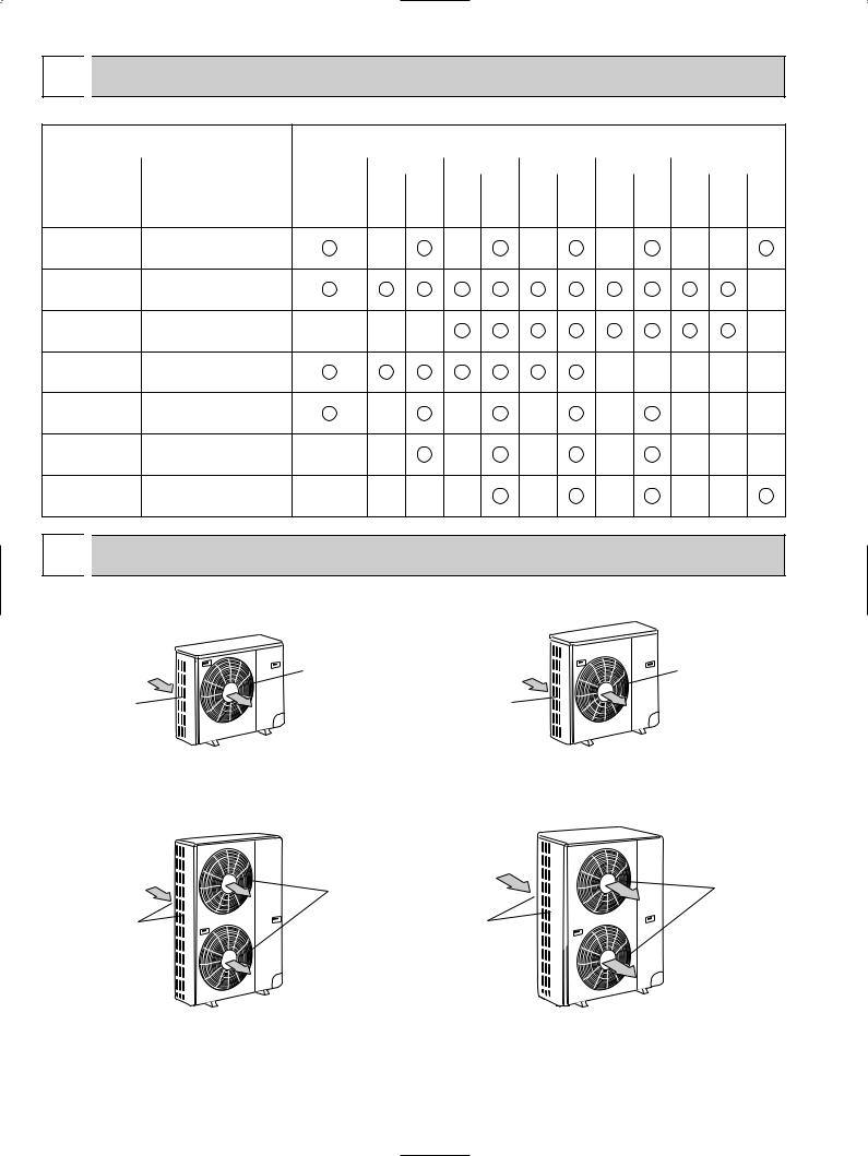
3. FOUR-WAY PIPING ACCESS MAKES INSTALLATION LAYOUT EASY
Piping on the outdoor unit may be connected from either of four directions: front, rear, side or beneath the base.
This easy-access design makes it possible to install a number of units in a compact arrangement at a single site. The outdoor unit allows for unheard-of flexibility in determining a piping layout, thus greatly simplifying installation.
|
Rear |
Front |
Right |
|
|
|
Base |
4. FRONT-ACCESS FACILITATES MAINTENANCE
The outdoor unit has been designed with a front-access service panel that allows easy access to all maintenance point, regardless of the installation layout. What’s more, this front panel may be removed by loosening only two screws. It all adds up to greatly simplified maintenance work.
2

2 
 TECHNICAL CHANGE
(OC247 REVISED EDITION-A)
Change of the service parts.
Refer to “13. PARTS LIST” for the details.
PU18EK PU18EK1
PU24EK PU24EK1
PU30EK PU30EK1
PU36EK PU36EK1
PU42EK2 PU42EK21
1.OUTDOOR CONTROLLER BOARD has been changed.
2.TRANSFORMER has been changed.
PU18EK PU18EK1
• CONTACTOR has been changed.
(OC247 REVISED EDITION-B) PU24EK1 PU24EK2 PU30EK1 PU30EK2 PU36EK1 PU36EK2
•COMPRESSOR has been changed.
(PU24EK model) NH33NBD NH33NBDT (PU30EK model) NH41NAD NH41NAHT (PU36EK model) NH47NAD NH47NAHT
Refer to “5. SPECIFICATIONS”, “6. DATA” and “13. PARTS LIST” for details.
PU42EK7 PU42EK71
1.COMPRESSOR CONTACTOR has been changed to the one equipped THERMAL RELAY. Refer to 8.WIRING DIAGRAM and 13.PARTS LIST for details.
2.OUTDOOR CONTROLLER BOARD has been changed. Refer to “13. PARTS LIST” for details.
(OC247 REVISED EDITION-D) PU24EK2 PU24EK3 PU30EK2 PU30EK3 PU36EK2 PU36EK3 PU42EK71 PU42EK72
• DRAIN PAN has been added.
<‘‘13. PARTS LIST’’ has been changed.>
PU36EK2 PU36EK3
• COMPRESSOR CAPACITOR for PU36EK, PU36EK1, PU36EK2 and PU36EK3 are unified.
3
3 
 COMBINATION OF INDOOR AND OUTDOOR UNITS
|
Indoor unit |
|
|
Outdoor unit |
|
|
||
|
|
|
PU |
|
|
|
||
|
|
|
|
|
|
|
||
|
|
12 |
18 |
24 |
30 |
36 |
42 |
|
Models |
Service |
|
|
EK1 |
EK1 |
EK1 |
EK7 |
|
manual No. |
|
|
||||||
EK |
EK EK1 |
EK EK2 |
EK EK2 |
EK EK2 |
EK2 EK21 EK71 |
|||
|
||||||||
|
|
|
|
EK3 |
EK3 |
EK3 |
EK72 |
|
PL • AK |
OC246 |
|
— |
— |
— |
— |
— |
— |
PL • FK(2) |
OC001 SECOND EDITION |
|
|
|
|
|
|
|
OC003 SECOND EDITION |
|
|
|
|
|
|
— |
|
|
OC194 |
|
|
|
|
|
|
|
PC • EK |
OC001 SECOND EDITION |
|
|
|
|
|
|
|
OC003 SECOND EDITION |
— |
— |
— |
|
|
|
— |
|
|
OC192 |
|
|
|
|
|
|
|
PK • EK |
OC001 SECOND EDITION |
|
|
|
|
— |
— — |
— — |
OC003 SECOND EDITION |
|
|
|
|
||||
|
|
|
|
|
|
|
|
PK • FK(3) |
OC121, OC196A |
|
— |
— |
— |
— |
— |
— |
— |
OC274 |
|
||||||||
|
|
|
|||||||
PK • FL(3) |
OC185A, OC275 |
— |
— |
— |
— |
— |
— |
— |
— |
PC • GK |
OC278 |
— |
— — |
— |
— |
— |
— |
— |
|
4 
 PART NAMES AND FUNCTIONS
Air outlet |
Air outlet |
Air intake |
Air intake |
PU12EK |
PU18EK |
Outdoor unit |
PU18EK1 |
|
Outdoor unit |
Air outlet |
Air outlet |
Air intake |
Air intake |
PU24EK |
PU30EK |
PU36EK |
PU42EK2 |
PU42EK7 |
PU24EK1 |
PU30EK1 |
PU36EK1 |
PU42EK21 |
PU42EK71 |
PU24EK2 |
PU30EK2 |
PU36EK2 |
|
PU42EK72 |
PU24EK3 |
PU30EK3 |
PU36EK3 |
|
|
Outdoor unit |
Outdoor unit |
|
||
4

5 
 SPECIFICATIONS
MODELS : PU12EK PU18EK PU24EK PU30EK PU36EK PU42EK2 PU42EK7 PU18EK1 PU24EK1 PU30EK1 PU36EK1 PU42EK21 PU42EK71 PU24EK2 PU30EK2 PU36EK2 PU42EK72
PU24EK3 PU30EK3 PU36EK3
|
|
Model |
PU12EK |
PU18EK |
|
PU24EK |
|
PU30EK |
PU36EK |
PU42EK2 |
PU42EK7 |
||||||||
Item |
|
|
|
|
|||||||||||||||
|
|
|
|
|
|
|
|
|
|
|
|
|
|
|
|
|
|
||
|
|
|
|
|
|
|
|
|
|
|
|
|
|
|
|
|
|
|
|
OUTDOOR UNIT MODELS |
|
|
PU18EK |
|
PU24EK |
PU24EK2 |
|
PU30EK |
PU30EK2 |
PU36EK |
|
PU36EK2 |
PU42EK2 |
PU42EK7 |
|||||
|
PU12EK |
|
|
|
PU42EK71 |
||||||||||||||
|
|
|
|
PU18EK1 |
|
PU24EK1 |
PU24EK3 |
|
PU30EK1 |
PU30EK3 |
PU36EK1 |
|
PU36EK3 |
PU42EK21 |
|||||
|
|
|
|
|
|
|
|
PU42EK72 |
|||||||||||
|
|
|
|
|
|
|
|
|
|
|
|
|
|
|
|
|
|
|
|
External finish |
|
|
|
|
|
|
|
Munsell 5Y 7/1 |
|
|
|
|
|
|
|||||
Power supply |
V, phase, Hz |
|
|
|
|
208/230, 1, 60 |
|
|
|
|
|
|
|||||||
Max.fuse size (time delay) |
A |
15 |
|
20 |
|
|
|
|
30 |
|
|
|
40 |
||||||
Min.ampacity |
|
A |
11 |
|
16 |
|
|
|
20 |
22 |
|
27 |
|
28 |
|||||
Fan motor |
F.L.A. |
0.65 |
0.75 |
|
|
0.65+0.65 |
|
0.75+0.75 |
|
0.8+0.8 |
|||||||||
|
|
Model (type) |
|
RH167NAB |
RH247NAB |
NH33NBD |
NH33NBDT |
NH41NAD |
NH41NAHT |
NH47NAD |
|
NH47NAHT |
|
NH569NXA |
|
ZR42K3PFV |
|||
Compressor |
R.L.A. |
8.9 |
12.0 |
|
11.5 |
|
10.8 |
|
14.0 |
12.9 |
17.5 |
|
15.1 |
|
20.0 |
|
20.4 |
||
|
|
L.R.A. |
29 |
37 |
|
52 |
|
57 |
|
73 |
75 |
87 |
|
81 |
|
105 |
|
109 |
|
Crankcase heater |
A(W) |
0.11/0.12(23/28) |
|
|
|
|
|
|
0.16/0.17(33/39) |
|
|
||||||||
Refrigerant control |
|
|
|
|
|
|
|
|
Capillary tube |
|
|
|
|
|
|
||||
Sound level |
|
dB |
50 |
53 |
|
|
|
|
55 |
|
|
|
|
|
|||||
|
|
|
|
|
|
|
|
|
56 |
||||||||||
|
|
W |
in. |
|
34-1/4 |
|
|
|
|
|
|
|
|
|
38-3/16 |
|
|
||
Dimensions |
D |
in. |
|
11-5/8 |
|
|
|
|
|
|
|
|
|
13-9/16 |
|
|
|||
|
|
H |
in. |
25-9/16 |
33-1/2 |
|
|
|
|
|
|
|
49-9/16 |
|
|
|
|
||
Weight |
|
lb |
105 |
154 |
|
207 |
|
208 |
|
220 |
|
222 |
|
260 |
|
220 |
|||
|
|
|
210 |
|
|
|
|||||||||||||
Control voltage (by built-in transformer) |
|
|
|
|
Indoor unit-outdoor unit:DC12V |
|
|
|
|||||||||||
|
|
Name |
|
|
|
|
|
|
|
|
R22 |
|
|
|
|
|
|
|
|
REFRIGERANT |
|
Charge |
|
4 lbs 14 oz |
5 lbs 8 oz |
9 lbs 15 oz |
|
10 lbs 2 oz |
10 lbs 9 oz |
|
12 lbs 9 oz |
|
11 lbs 0 oz |
||||||
|
|
Oil<Model> OZ |
16<MS-56> |
|
37<MS32(N-1)> |
|
40<MS32(N-1)> |
|
49<MS32(N-1)> |
|
42<SONTEX 200LT> |
||||||||
REFRIGERANT PIPING |
|
|
|
|
|
Not supplied(optional parts) |
|
|
|
||||||||||
Pipe size |
Liquid |
in. |
|
3/8 |
|
|
|
|
|
|
|
|
1/2 |
|
|
||||
Gas |
in. |
|
5/8 |
|
|
|
|
|
|
|
|
3/4 |
|
|
|||||
|
|
|
|
|
|
|
|
|
|
|
|
|
|||||||
Connection |
Indoors |
|
|
|
|
|
|
|
|
Flared |
|
|
|
|
|
|
|
||
method |
Outdoors |
|
|
|
|
|
|
|
|
Flared |
|
|
|
|
|
|
|
||
Between the indoor |
Height difference |
ft |
Max. 130 |
|
|
|
|
|
|
|
Max, 164 |
|
|
|
|||||
|
|
|
|
|
|
|
|
|
|
||||||||||
& outdoor units |
Piping length |
ft |
Max. 130 |
|
|
|
|
|
|
|
Max. 164 |
|
|
|
|||||
Operating range
|
Indoor intake air temperature |
Outdoor intake air temperature |
|
Maximum |
D.B. 95˚F, |
W.B. 71˚F |
D.B. 115˚F |
Cooling |
D.B. 67˚F, |
W.B. 57˚F |
D.B. 0˚F w |
Minimum |
|||
w In case of the wind baffle installed.
(In case of the wind baffle is not installed, the minimum temperature is D.B. 23˚F)
5

6 |
|
|
DATA |
|
|
|
|
|
|
|
|
|
|
|
|
|
|
|
|
|
|
||
|
|
|
|
|
|
|
|
|
|
|
|
|
|
|
|
|
|
|
|
|
|
||
1. ADDITIONAL REFRIGERANT CHARGE (R22 : oz) |
|
|
|
|
|
|
|
|
|
||||||||||||||
|
|
|
|
|
|
|
|
|
|
|
|
|
|
|
|
|
|
|
|
|
|||
Service Ref. |
|
|
|
|
Piping length (one way) |
|
|
|
|
|
|
|
Factory |
||||||||||
100 ft |
|
115 ft |
|
|
130 ft |
|
145 ft |
|
160 ft |
|
164 ft |
|
charged |
||||||||||
|
|
|
|
|
|
|
|
|
|
|
|
||||||||||||
PU12EK |
0 |
2 |
|
4 |
|
|
— |
|
— |
|
|
— |
|
4 lbs 14 oz |
|||||||||
|
|
|
|
|
|
|
|
|
|
|
|
|
|
|
|
|
|
|
|
|
|
||
PU18EK |
0 |
2 |
|
4 |
|
|
— |
|
— |
|
|
— |
|
5 lbs 8 oz |
|||||||||
PU18EK1 |
|
|
|
|
|
|
|
||||||||||||||||
|
|
|
|
|
|
|
|
|
|
|
|
|
|
|
|
|
|
|
|||||
|
|
|
|
|
|
|
|
|
|
|
|
|
|
|
|
|
|
|
|
|
|
||
PU24EK |
|
|
|
|
|
|
|
|
|
|
|
|
|
|
|
|
|
|
|
||||
PU24EK1 |
0 |
2 |
|
4 |
|
6 |
|
8 |
|
|
9 |
|
|
9 lbs 15 oz |
|||||||||
PU24EK2 |
|
|
|
|
|
|
|
||||||||||||||||
|
|
|
|
|
|
|
|
|
|
|
|
|
|
|
|
|
|
|
|||||
PU24EK3 |
|
|
|
|
|
|
|
|
|
|
|
|
|
|
|
|
|
|
|
||||
PU30EK |
|
|
|
|
|
|
|
|
|
|
|
|
|
|
|
|
|
|
|
||||
PU30EK1 |
0 |
5 |
|
10 |
|
14 |
|
19 |
|
|
20 |
|
|
10 lbs 2 oz |
|||||||||
PU30EK2 |
|
|
|
|
|
|
|
||||||||||||||||
|
|
|
|
|
|
|
|
|
|
|
|
|
|
|
|
|
|
|
|||||
PU30EK3 |
|
|
|
|
|
|
|
|
|
|
|
|
|
|
|
|
|
|
|
||||
PU36EK |
|
|
|
|
|
|
|
|
|
|
|
|
|
|
|
|
|
|
|
||||
PU36EK1 |
0 |
5 |
|
10 |
|
14 |
|
19 |
|
|
20 |
|
|
10 lbs 9 oz |
|||||||||
PU36EK2 |
|
|
|
|
|
|
|
|
|
|
|
|
|
|
|
|
|
|
|
||||
PU36EK3 |
|
|
|
|
|
|
|
|
|
|
|
|
|
|
|
|
|
|
|
||||
PU42EK2 |
0 |
5 |
|
10 |
|
14 |
|
19 |
|
|
20 |
|
|
12 lbs 9 oz |
|||||||||
PU42EK21 |
|
|
|
|
|
|
|
||||||||||||||||
|
|
|
|
|
|
|
|
|
|
|
|
|
|
|
|
|
|
|
|||||
|
|
|
|
|
|
|
|
|
|
|
|
|
|
|
|
|
|
|
|
|
|
||
PU42EK7 |
0 |
5 |
|
10 |
|
14 |
|
19 |
|
|
20 |
|
|
11 lbs 0 oz |
|||||||||
PU42EK71 |
|
|
|
|
|
|
|
||||||||||||||||
PU42EK72 |
|
|
|
|
|
|
|
|
|
|
|
|
|
|
|
|
|
|
|
||||
|
|
|
|
|
|
|
|
|
|
|
|
|
|
|
|
|
|
|
|
|
|||
2. COMPRESSOR TECHNICAL DATA |
|
at 68°F (Only PU42EK7 PU42EK71 : at 77°F) |
|||||||||||||||||||||
|
|
|
|
|
|
|
|
|
|
|
|
|
|||||||||||
|
|
|
|
|
|
|
|
|
|
|
|
|
|
|
|
|
|
|
|||||
Unit |
|
|
PU12EK |
|
PU18EK |
|
PU24EK |
|
PU24EK2 |
|
|
|
PU30EK |
|
PU30EK2 |
|
|||||||
|
|
|
PU18EK1 |
|
PU24EK1 |
|
PU24EK3 |
|
|
|
PU30EK1 |
|
PU30EK3 |
|
|||||||||
|
|
|
|
|
|
|
|
|
|
|
|
|
|
||||||||||
Compressor model |
|
RH167NAB |
|
RH247NAB |
|
NH33NBD |
|
NH33NBDT |
|
NH41NAD |
|
NH41NAHT |
|
||||||||||
|
|
|
|
|
|
|
|
|
|
|
|
|
|
|
|
|
|
|
|||||
Winding |
R-C |
|
2.47 |
|
1.59 |
|
|
0.92 |
|
|
0.92 |
|
|
|
0.63 |
|
0.62 |
|
|||||
Resistance |
|
|
|
|
|
|
|
|
|
|
|
|
|
|
|
|
|
|
|
|
|
||
S-C |
|
4.62 |
|
3.22 |
|
|
1.93 |
|
|
1.93 |
|
|
|
1.37 |
|
1.51 |
|
||||||
( " ) |
|
|
|
|
|
|
|
|
|
|
|
|
|||||||||||
|
|
|
|
|
|
|
|
|
|
|
|
|
|
|
|
|
|
||||||
|
|
|
|
|
|
|
at 68°F(Only PU42EK7 PU42EK71 : at 77°F) |
|
|
|
|
|
|
|
|||||||||
|
|
|
|
|
|
|
|
|
|
|
|
|
|
|
|
|
|
|
|
|
|
|
|
|
|
|
|
|
PU36EK |
|
PU36EK2 |
|
PU42EK2 |
|
PU42EK7 |
|
|
|
|
|
|
|
|
|
|||
Unit |
|
|
|
|
|
PU42EK71 |
|
|
|
|
|
|
|
|
|||||||||
|
|
PU36EK1 |
|
PU36EK3 |
|
PU42EK21 |
|
|
|
|
|
|
|
|
|
||||||||
|
|
|
|
|
|
|
|
PU42EK72 |
|
|
|
|
|
|
|
|
|||||||
|
|
|
|
|
|
|
|
|
|
|
|
|
|
|
|
|
|
|
|
|
|||
Compressor model |
|
NH47NAD |
|
NH47NAHT |
|
NH569NXA |
|
ZR42K3PFV |
|
|
|
|
|
|
|
|
|||||||
|
|
|
|
|
|
|
|
|
|
|
|
|
|
|
|
|
|
|
|
|
|||
Winding |
R-C |
|
0.55 |
|
0.52 |
|
|
0.55 |
|
|
0.54 |
|
|
|
|
|
|
|
|
|
|||
Resistance |
|
|
|
|
|
|
|
|
|
|
|
|
|
|
|
|
|
|
|
|
|
||
S-C |
|
1.24 |
|
1.28 |
|
|
1.24 |
|
|
1.28 |
|
|
|
|
|
|
|
|
|
||||
( " ) |
|
|
|
|
|
|
|
|
|
|
|
|
|
|
|
|
|||||||
|
|
|
|
|
|
|
|
|
|
|
|
|
|
|
|
|
|
|
|
|
|
|
|
6

3. NOISE CRITERION CURVES
PU12EK |
|
|
|
|
SPL(dB) |
LINE |
|||
|
|
|
|
|
|
|
|
50 |
|
BAR |
90 |
|
|
|
|
|
|
|
|
|
|
|
|
|
|
|
|
|
|
0.0002 MICRO |
80 |
|
|
|
|
|
|
|
|
70 |
|
|
|
|
|
|
|
NC-70 |
|
dB re |
|
|
|
|
|
|
|
|
|
|
|
|
|
|
|
|
|
|
|
LEVEL, |
60 |
|
|
|
|
|
|
|
|
|
|
|
|
|
|
|
|
NC-60 |
|
|
|
|
|
|
|
|
|
|
|
PRESSURE |
50 |
|
|
|
|
|
|
|
|
|
|
|
|
|
|
|
|
NC-50 |
|
40 |
|
|
|
|
|
|
|
|
|
|
|
|
|
|
|
|
|
NC-40 |
|
SOUND |
|
|
|
|
|
|
|
|
|
30 |
|
|
|
|
|
|
|
|
|
|
|
|
|
|
|
|
|
|
|
BAND |
|
|
|
|
|
|
|
|
NC-30 |
20 |
APPROXIMATE |
|
|
|
|
|
|
||
OCTAVE |
|
|
|
|
|
|
|||
|
THRESHOLD OF |
|
|
|
|
|
|
||
|
HEARING FOR |
|
|
|
|
|
NC-20 |
||
|
CONTINUOUS |
|
|
|
|
|
|||
|
|
|
|
|
|
|
|||
|
NOISE |
|
|
|
|
|
|
|
|
10 |
|
|
|
|
|
|
|
|
|
|
63 |
125 |
250 |
500 |
1000 |
2000 |
4000 |
8000 |
|
|
|
||||||||
BAND CENTER FREQUENCIES, Hz
PU24EK |
PU30EK |
|
|
|
|
|
||||
PU24EK1 |
PU30EK1 |
|
|
|
|
|
||||
PU24EK2 |
PU30EK2 |
|
|
SPL(dB) |
LINE |
|||||
PU24EK3 |
PU30EK3 |
|
|
|
55 |
|
||||
BAR |
90 |
|
|
|
|
|
|
|
|
|
|
|
|
|
|
|
|
|
|
||
MICRO |
80 |
|
|
|
|
|
|
|
|
|
|
|
|
|
|
|
|
|
|
||
0.0002 |
70 |
|
|
|
|
|
|
|
NC-70 |
|
|
|
|
|
|
|
|
|
|||
dB re |
|
|
|
|
|
|
|
|
||
60 |
|
|
|
|
|
|
|
|
||
LEVEL, |
|
|
|
|
|
|
|
|
||
|
|
|
|
|
|
|
|
NC-60 |
||
|
|
|
|
|
|
|
|
|
||
PRESSURE |
50 |
|
|
|
|
|
|
|
|
|
|
|
|
|
|
|
|
|
NC-50 |
||
40 |
|
|
|
|
|
|
|
|
||
|
|
|
|
|
|
|
|
NC-40 |
||
SOUND |
|
|
|
|
|
|
|
|
||
30 |
|
|
|
|
|
|
|
|
||
|
|
|
|
|
|
|
|
NC-30 |
||
BAND |
|
|
|
|
|
|
|
|
||
20 |
APPROXIMATE |
|
|
|
|
|
|
|||
OCTAVE |
|
|
|
|
|
|
||||
|
THRESHOLD OF |
|
|
|
|
|
|
|||
|
HEARING FOR |
|
|
|
|
|
NC-20 |
|||
|
CONTINUOUS |
|
|
|
|
|
||||
|
|
|
|
|
|
|
||||
|
NOISE |
|
|
|
|
|
|
|
||
10 |
63 |
125 |
250 |
500 |
1000 |
2000 |
4000 |
8000 |
||
|
||||||||||
|
|
|||||||||
BAND CENTER FREQUENCIES, Hz
PU18EK |
|
|
|
|
SPL(dB) |
LINE |
||||
PU18EK1 |
|
|
|
|
|
53 |
|
|||
|
|
|
|
|
|
|
||||
BAR |
90 |
|
|
|
|
|
|
|
|
|
|
|
|
|
|
|
|
|
|
||
0.0002 MICRO |
80 |
|
|
|
|
|
|
|
|
|
70 |
|
|
|
|
|
|
|
NC-70 |
||
dB re |
|
|
|
|
|
|
|
|
||
60 |
|
|
|
|
|
|
|
|
||
LEVEL, |
|
|
|
|
|
|
|
|
||
|
|
|
|
|
|
|
|
NC-60 |
||
|
|
|
|
|
|
|
|
|
||
PRESSURE |
50 |
|
|
|
|
|
|
|
|
|
|
|
|
|
|
|
|
|
NC-50 |
||
40 |
|
|
|
|
|
|
|
|
||
|
|
|
|
|
|
|
|
NC-40 |
||
SOUND |
|
|
|
|
|
|
|
|
||
30 |
|
|
|
|
|
|
|
|
||
|
|
|
|
|
|
|
|
NC-30 |
||
BAND |
|
|
|
|
|
|
|
|
||
20 |
APPROXIMATE |
|
|
|
|
|
|
|||
OCTAVE |
|
|
|
|
|
|
||||
|
THRESHOLD OF |
|
|
|
|
|
|
|||
|
HEARING FOR |
|
|
|
|
|
NC-20 |
|||
|
CONTINUOUS |
|
|
|
|
|
||||
|
|
|
|
|
|
|
||||
|
NOISE |
|
|
|
|
|
|
|
||
10 |
63 |
125 |
250 |
500 |
1000 |
2000 |
4000 |
8000 |
||
|
||||||||||
|
|
|||||||||
BAND CENTER FREQUENCIES, Hz
PU36EK |
|
|
|
|
|
|
|
|||
PU36EK1 |
|
|
|
|
|
|
|
|||
PU36EK2 |
|
|
|
|
SPL(dB) |
LINE |
||||
PU36EK3 |
|
|
|
|
|
55 |
|
|||
BAR |
90 |
|
|
|
|
|
|
|
|
|
|
|
|
|
|
|
|
|
|
||
0.0002 MICRO |
80 |
|
|
|
|
|
|
|
|
|
70 |
|
|
|
|
|
|
|
NC-70 |
||
dB re |
|
|
|
|
|
|
|
|
||
60 |
|
|
|
|
|
|
|
|
||
LEVEL, |
|
|
|
|
|
|
|
|
||
|
|
|
|
|
|
|
|
NC-60 |
||
|
|
|
|
|
|
|
|
|
||
PRESSURE |
50 |
|
|
|
|
|
|
|
|
|
|
|
|
|
|
|
|
|
NC-50 |
||
40 |
|
|
|
|
|
|
|
|
||
|
|
|
|
|
|
|
|
NC-40 |
||
SOUND |
|
|
|
|
|
|
|
|
||
30 |
|
|
|
|
|
|
|
|
||
|
|
|
|
|
|
|
|
NC-30 |
||
BAND |
|
|
|
|
|
|
|
|
||
20 |
APPROXIMATE |
|
|
|
|
|
|
|||
OCTAVE |
|
|
|
|
|
|
||||
|
THRESHOLD OF |
|
|
|
|
|
|
|||
|
HEARING FOR |
|
|
|
|
|
NC-20 |
|||
|
CONTINUOUS |
|
|
|
|
|
||||
|
|
|
|
|
|
|
||||
|
NOISE |
|
|
|
|
|
|
|
||
10 |
63 |
125 |
250 |
500 |
1000 |
2000 |
4000 |
8000 |
||
|
||||||||||
|
|
|||||||||
BAND CENTER FREQUENCIES, Hz
7

PU42EK2 |
PU42EK7 |
|
|
|
|
|
||||
PU42EK21 |
PU42EK71 |
|
SPL(dB) |
LINE |
|
|||||
|
|
|
PU42EK72 |
|
|
56 |
|
|
||
BAR |
90 |
|
|
|
|
|
|
|
MICROPHONE |
UNIT |
|
|
|
|
|
|
|
|
|||
MICRO |
|
|
|
|
|
|
|
|
||
80 |
|
|
|
|
|
|
|
3.3ft |
|
|
|
|
|
|
|
|
|
|
|
||
0.0002 |
|
|
|
|
|
|
|
|
|
|
70 |
|
|
|
|
|
|
|
3.3ft |
|
|
|
|
|
|
|
|
|
|
|
||
|
|
|
|
|
|
|
|
NC-70 |
|
|
dB re |
|
|
|
|
|
|
|
|
|
|
60 |
|
|
|
|
|
|
|
|
|
|
LEVEL, |
|
|
|
|
|
|
|
|
|
|
|
|
|
|
|
|
|
|
NC-60 |
|
|
|
|
|
|
|
|
|
|
|
|
|
PRESSURE |
50 |
|
|
|
|
|
|
|
NC-50 |
GROUND |
|
|
|
|
|
|
|
|
|
||
|
40 |
|
|
|
|
|
|
|
|
|
SOUND |
|
|
|
|
|
|
|
|
NC-40 |
|
30 |
|
|
|
|
|
|
|
|
|
|
|
|
|
|
|
|
|
|
|
|
|
BAND |
|
|
|
|
|
|
|
|
NC-30 |
|
20 |
APPROXIMATE |
|
|
|
|
|
|
|
||
OCTAVE |
THRESHOLD OF |
|
|
|
|
|
|
|
||
10 |
|
|
|
|
|
|
|
|||
|
|
HEARING FOR |
|
|
|
|
|
NC-20 |
|
|
|
|
CONTINUOUS |
|
|
|
|
|
|
||
|
|
|
|
|
|
|
|
|
||
|
|
NOISE |
|
|
|
|
|
|
|
|
|
|
63 |
125 |
250 |
500 |
1000 |
2000 |
4000 |
8000 |
|
|
|
|
BAND CENTER FREQUENCIES, Hz |
|
|
|||||
8

7 OUTLINES AND DIMENSIONS
Outdoor Unit PU12EK
Unit : inch
necessary surrounding clearance |
|
clearance.upper |
Frontopening |
|
Service space |
(for N.E.C) |
36 |
connection |
|
|
|
|
|
|
5/8 flaredpipe-Refrigerant |
connection |
3/8 |
holeoutKnock -23/8 |
Knock out holes |
1/16 |
holeoutKnock |
|
drainage(refrigerant, wiring)and |
|
Standardbolt length |
|
||
|
Note:Allowadequate |
1/2 1/2 |
|
|
|
|
|
|
|
wiring)and forpowerline1- |
|
|
|
|
||||||||||||||
|
|
|
|
|
4 |
|
|
|
|
|
|
|
|
|
|
1 - 3/4 |
|
|
2 - 1/16 |
|
|
|
|
|
|
|
|
|
|
8 |
|
|
|
|
|
|
|
|
|
|
|
|
|
|
|
|
|
|
|
|
|
|
|
|
|
|
|
|
|
|
|
|
36 |
|
|
|
|
|
|
|
|
|
|
|
|
|
|
|
|
|
|
|
|
|
31/32 .max |
|
|
|
|
|
|
|
|
|
|
|
|
|
|
|
|
|
|
|
|
|
|
|
3/4 |
|
|
|
|
3 - 5/32 |
|
|
|
|
|
|
|
|
|
|
|
|
|
|
|
|
|
|
|
|
|
|
|
- 4 |
|
|
|
|
|
|
OutdoorUnit - |
|
|
|
|
|
|
|
|
outdoorandindoorforbedTerminalunit |
|
|
|
|
-pipeflared |
|
|
|
|
|
|
|
|
|
|
|
R25/32 |
|
|
-9/32 |
|
|
|
|
1/2 |
|
|
linepowerforbedTerminal |
terminalGround |
movingforHandle |
panelService |
|
|
|
|
3/8-2 pipingfrontfor |
|
drainage(refrigerant, |
1/8-4 |
5/16-1 |
pipingfrontfor |
Bottom holepiping |
shaped-U-2 |
notched holes |
15/32 |
|||
|
|
|
|
|
|
|
|
|
|
|
|
|||||||||||||||||
|
|
|
|
|
|
|
|
|
|
|
|
|
|
Refrigerant |
connection |
|
|
|
|
|
|
|
|
|
|
R25/32 |
|
|
|
|
|
|
|
|
|
|
|
|
|
|
|
|
|
|
|
|
|
|
|
|
|
|
|
21/32 |
|
||
|
|
|
|
|
|
|
|
|
|
|
|
|
|
|
|
|
|
|
|
|
|
|
|
|
|
|
|
|
|
|
|
|
|
|
|
|
|
|
|
|
|
|
25-9/16 |
|
|
|
|
|
|
|
|
|
|
1/4 |
|
||
|
|
|
|
|
|
|
|
|
|
|
|
|
|
|
|
|
|
|
|
|
|
|
|
|
|
|
||
|
|
|
|
|
|
|
|
|
|
|
|
|
|
|
|
|
|
|
|
|
|
1-25/32 |
|
|
|
R |
|
|
|
|
|
|
|
|
|
|
|
|
|
|
|
|
17-15/32 |
|
|
|
|
|
|
|
|
|
|
||||
|
|
14-1/4 |
|
|
|
|
|
|
|
|
|
|
|
|
|
|
1-21/32 |
|
|
|
|
|
||||||
|
|
|
|
|
|
|
|
|
|
|
|
|
11-11/16 |
|
|
|
|
|
|
|
|
|||||||
|
|
|
|
|
|
|
|
|
|
|
|
|
|
|
|
|
|
|
|
|
|
|
|
|||||
|
11/16 |
13 |
|
9/16 |
|
|
|
|
|
|
|
|
|
|
|
|
|
|
|
|
|
|
|
|
||||
|
|
|
|
|
|
|
|
|
|
|
|
11-3/32 |
|
|
|
|
|
|
|
|
|
|
||||||
|
|
1-3/32 |
1-9/16 |
|
|
|
|
|
|
|
|
|
|
|
|
|
|
|
|
|
|
|
|
|||||
|
|
|
|
|
|
|
|
|
|
|
|
|
|
|
|
|
|
|
|
|
|
|
|
|
||||
|
7 |
|
|
|
|
|
|
|
|
|
|
|
|
|
|
|
|
|
|
|
|
|
|
|
|
|
|
|
19-11/16 |
Air in |
34-1/4 |
7-9/32 |
Air out |
11-7/8 |
|
|
Airin |
|
|
Outletguide |
installationhole |
forHandle |
moving |
20-5/8 |
3-1/32 |
|
|
|
|
|
13-11/32 |
|||||
|
|
|
|
|
|
|
|
|
|
|
|
|
|
|
|
1 |
|
|
|
|
|
|
|
|
|
|
11-5/8 |
|
|
|
|
|
|
|
mustsidebe open. |
8 |
40 |
9/32 |
|
Rearfresh |
airintake |
airSideintake |
|
|
|
|
|
|
|
|
|
|
|
|
surrounding clearance |
installation) |
The upper |
|
10 units or less |
|
|
|
|
|
|
Unit-Necessary |
(Concentrated |
|
1/2 |
For |
|
|
|
|
|
|
Outdoor |
|
|
4 |
|
moving |
|
|
|
|
5-7/16 |
|
|
|
|
|
Handle for |
|
|
|
|
|
20-5/8 |
15/32 29/32 Oval holes (standard bolt M10) |
Drain hole |
1-9/16 |
|
hole |
|
|
Drain |
1-5/16 |
|
|
29/32
Rear piping hole 3-3/4
2-9/16 |
right piping holes - detail Figures |
|
Front |
9

Outdoor Unit PU18EK
PU18EK1
surroundingnecessaryclearance |
|
Note:Allowadequate |
clearance. |
openingFront |
|
Servicespace |
N.E.C)(for 36 |
|
1/2 |
|
|||||
|
8 |
|
upper |
|
4 |
|
|
|
|
|
|
|
36 |
|
|
Unit |
|
|
|
|
|
1/2 |
|
Outdoor |
|
|
1/2 |
|
|
|
|
|
|
14-1/4 |
|
11/16 |
13 |
9/16 |
|
|
|
1-9/161-1/16 |
|
7-9/32 |
|
|
|
11/16 |
Air intake |
|
|
19- |
|
|
|
7-9/32 |
|
|
Air outlet |
|
|
Air intake |
|
|
open. |
|
|
|
mustbe |
8 |
40 |
|
|
|
|
surrounding clearance |
installation) The upper side |
|
10 units or less |
Unit-Necessary |
(Concentrated |
1/2 |
For |
Outdoor |
|
4 |
|
Unit : inch
|
|
|
|
|
|
|
|
holes for 1-1/16 |
|
|
|
|
|
|
|
|
out line |
|
|
|
|
|
1-3/4 |
2-1/16 |
Knock power |
|
|
|
|
|
|
|
|||
connection |
|
|
|
|
|
|
2-3/8 |
4-3/4 |
unit |
blockTerminalfor power line |
Ground terminal movingforHandle |
panelService |
|
|
|
|
(refrigerant.drainage andwiring) |
blockTerminalfor indoor and outdoor |
Refrigerant pipe |
(Flared) 5/8 |
Refrigerant pipe (Flared) 3/8 |
3/8-2 |
||||
|
|
|
|
holeoutKnock pipingfrontfor |
|
|||
|
|
|
|
33-1/2 |
|
|
|
|
|
|
|
|
21-3/4 |
|
|
|
|
|
|
|
|
|
|
13-7/8 |
|
|
|
|
|
|
|
13-7/4 |
|
|
|
|
|
|
|
15-7/8 |
|
|
||
34-1/4 |
|
|
|
|
|
|
|
|
|
7/8 |
|
|
|
|
|
20-5/8 |
|
|
11- |
|
|
|
|
|
|
|
|
|
|
|
20-5/18 |
|
7-1/18 |
-9/16 |
|
|
|
|
|
|
|
|
1 |
|
|
|
Outlet guide installation hole |
|
17-3/18 |
|
|
|
|
|
1 |
|
Handlefor moving |
|
|
2 |
|
|
|
11-5/8 |
|
|
|
|
|
|
|
|
1/4 |
|
|
|
|
|
|
|
|
|
|
|
|
|
|
1 |
|
|
|
Side air intake |
|
Rear fresh air intake |
|
|
|
|
Rear piping hole
3-3/4
for |
5-7/16 |
Handle |
moving |
|
|
R13/16 |
|
|
|
|
(refrigerant. drainage |
R13/16 |
|
Knock out hole for right piping |
and wiring) |
hole |
||
|
|
|
|
piping |
|
1-3/4 |
|
|
Bottom |
|
|
|
|
|
|
1-5/8 |
|
|
|
4-1/8 |
1-5/16 |
|
|
|
Oval holes |
W3/8(M10) |
|
|
|
1/2x7/8 |
(standard bolt |
|
|
|
|
|
|
Drain hole |
|
1.max |
Standard bolt length |
|
|
|
|
3-1/8 |
|
rightpiping holesfigures |
|
2-9/16 |
|
|
|
Front detail |
|
11/16 |
|
R1/4 |
|
|
|
|
1/2 |
|
2-U-shaped notched holes |
|
Drain hole
10
Outdoor Unit PU24EK PU30EK PU24EK1 PU30EK1 PU24EK2 PU30EK2 PU24EK3 PU30EK3
necessary-UnitOutdoor surrounding clearance |
|
Note:Allow adequate upper clearance. 1/2 1/2 |
Frontopening |
|
forblockTerminal outdoorandindoor |
connectionunit |
linepowerforblockTerminal |
|
12 |
|
|
4 |
space Service |
N.E.C) (for |
|
|
|
|
|
36 |
|
|
|
|
|
|
|
|
|
36 |
|
|
|
|
|
|
3/8 |
|
|
|
|
|
|
14-1/4 |
|
|
|
|
|
11/16 |
13 |
|
9/16 |
||
|
|
|
|
1-9/161-1/16 |
|
|
|
|
|
7-9/32 |
|
|
|
|
|
|
|
11/16 |
Air intake |
|
|
34-1/4 |
|
|
|
19- |
|
|
|
|
|
|
|
7-9/32 |
|
|
|
Air outlet |
11-7/8 |
|
|
|
|
Air intake |
|
|
Outlet guide installation hole |
|
|
|
|
|
|
|
1 |
Service panel
Unit : inch
|
49-9/16 |
Ground terminal |
Handle for moving |
1-3/4
RefrigerantPU24EK [PU30EK [RefrigerantPU24EK [PU30EK [ (Flared)pipe5/83/4 (Flared)pipe3/81/2
37-34 15-7/8
15-1/16
|
holes for 1-1/16 |
|
|
|
|
out line |
|
|
|
2-1/16 |
Knock power |
|
|
|
-3/8 |
4-3/4 |
|
R13/16 |
|
2 |
|
|
||
|
|
|
|
R13/16 |
Knock out hole for front piping |
(refrigerant. drainage and wiring) |
Knock out hole |
for right piping |
(refrigerant. drainage and wiring) |
3/8 |
Bottom pipinghole |
|||
|
|
2-1/4 |
|
|
2- |
|
2-1/16 |
|
|
1/8 |
1-9/16 |
|
|
|
|
4- |
|
|
|
Standard bolt length |
|
1.max |
|
3-1/8 |
|
2-9/16 |
right piping holesfigures |
|
Front detail |
11/16 |
|
R1/4
1/2
2-U-shaped notched holes
|
|
|
|
20-5/8 |
2-1/2x7/8 Oval holes bolt M10)W3/8(M10) |
Drain hole |
|
|
|
|
-9/16 |
(standard |
|
20-5/8 |
2-3/8 |
20-5/8 |
3-1/4 |
|
|
|
1 |
|
hole |
||||
|
23-1/16 |
|
13-9/16 |
|
||
|
|
moving |
|
|
|
Drain |
|
|
for |
|
|
|
|
|
|
Handle |
|
2 |
|
|
|
|
|
|
|
11-5/8 |
|
|
|
|
|
|
|
1/4 |
|
|
|
|
mustbe open. |
12 |
40 |
Side air intake |
Rear fresh |
air intake |
surrounding clearance |
installation) |
The upper side |
|
10 units or less |
|
|
|
Outdoor Unit-Necessary |
(Concentrated |
|
6 1/2 |
For |
|
Handle for moving |
|
1
Rear piping hole
3-3/4
5-7/16
11
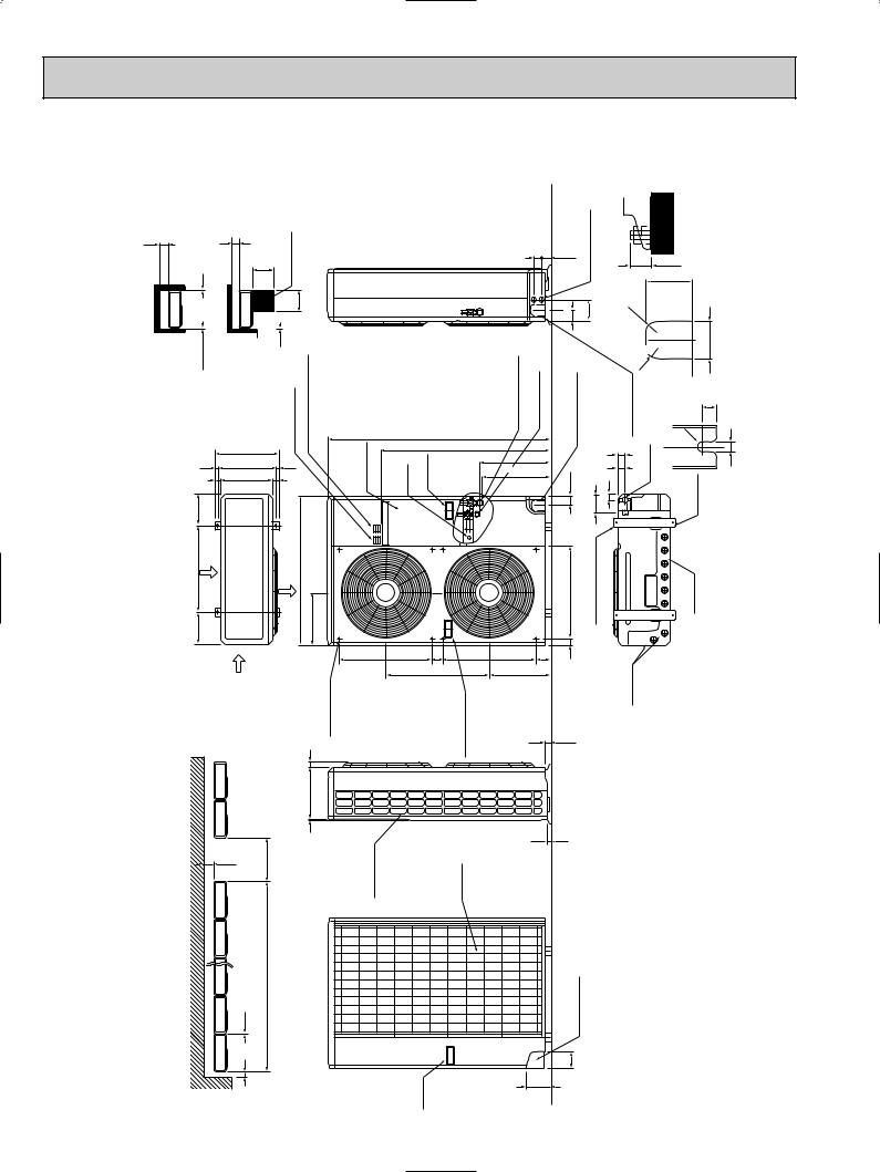
Outdoor Unit PU36EK |
PU42EK2 |
PU42EK7 |
PU36EK1 |
PU42EK21 |
PU42EK71 |
PU36EK2 |
|
PU42EK72 |
PU36EK3 |
|
|
Outdoor Unit - necessary surrounding clearance
12
Note:Allow adequate |
upper clearance. |
1/2 |
opening |
|
Front |
1/2 |
|
11/16 |
|
7-9/32 |
|
5/8 |
Air intake |
23- |
|
7-9/32 |
|
6 |
spaceService |
N.E.C)(for |
36 |
|
|
|
|
36 |
1/2 |
|
|
Terminal block for |
indoor and outdoor unit connection |
Terminal block for power line |
16-1/4 |
|
|
14-31/32 |
9/16 |
|
1-9/161-1/16 |
|
|
|
38-3/16 |
|
|
Air outlet |
13-7/8 |
Air intake |
|
Outlet guide installation hole |
|
|
1 |
Service panel
|
49-9/16 |
Ground terminal |
Handle for moving |
20-5/8 |
2-3/8 |
|
23-1/16 |
clearance |
be open. |
|
|
1/4 13-9/16 |
freshRear |
sideupperThemust |
12 |
40 |
airSideintake |
||
Outdoor Unit-Necessary surrounding |
(Concentrated installation) |
6 1/2 |
For 10 units or less |
|
|
|
|
|
|
|
Handle for moving |
37-3/4
20-5/8
Handle for moving
air intake
Unit : inch
|
|
|
holes for |
1-1/16 |
|
|
|
|
|
|
|
out line |
|
|
|
||
1-3/4 |
2-1/16 |
Knock |
power |
|
|
|
||
|
|
2-3/8 |
4-3/4 |
|
R13/16 |
|||
Refrigerantpipe (Flared) [3/4 |
Refrigerantpipe Flared) [1/2 |
holeoutKnock pipingfrontfor |
drainage(refrigerant. wiring)and |
holeoutKnock |
||||
pipingrightfor |
(refrigerant. anddrainagewiring) |
|||||||
|
|
|
|
|
|
|
R13/16 |
|
|
|
3/8-2 |
|
1/8 |
9/16-1 |
|
Bottom piping hole |
|
15 - 7/8 |
|
|
|
2 - 1/4 |
|
|
||
15-1/16 |
|
|
2-1/16 |
|
|
|||
|
|
|
|
|
|
|||
|
|
|
|
4- |
|
|
|
|
|
|
|
|
Oval holes |
W3/8(M10) |
|
|
|
|
|
20-5/8 |
|
2-1/2x7/8 |
(standard bolt |
|
|
|
|
3-1/4 |
-9/16 |
|
|
|
|
|
|
|
1 |
|
|
|
hole |
|
||
13-9/16 |
|
|
|
|
||||
|
|
|
|
|
|
Drain |
|
|
|
|
1-5/16 |
|
|
|
|
|
|
7/8
Rear piping hole 3-3/4
5-7/16
Standard bolt length |
|
|
1.max |
|
|
3-1/8 |
|
|
2-9/16 |
right piping holes- |
figures |
|
Front |
detail |
11/16 |
|
|
R1/4
1/2
2-U-shaped notched holes
Drain hole
12
8 |
|
|
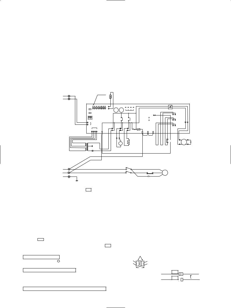
WIRING DIAGRAM |
|
|
|
||
|
|
|
|
|
|
|
|
|
MODEL : PU12EK |
PU18EK 1 |
|
|
|
|
|||
|
|
|
|
|
|
|
||
SYMBOL |
NAME |
|
SYMBOL |
NAME |
SYMBOL |
NAME |
||
|
|
|
|
|
|
|||
C |
COMPRESSOR CAPACITOR |
LD1 ~ LD8 |
LED <CHECK, SERVICE> |
TH3 |
OUTDOOR COIL THERMISTOR |
|||
|
|
|
|
|
|
|
||
C3 |
FAN CAPACITOR |
|
MC |
COMPRESSOR |
X11 <O. B> |
CRANKCASE HEATER RELAY |
||
|
|
|
|
|
|
|
||
CH |
CRANKCASE HEATER |
|
MF |
OUTDOOR FAN MOTOR (INNER THERMOSTAT) |
X12 <O. B> |
COMPRESSOR RELAY |
||
|
|
|
|
|
|
|
|
|
CN3<O. B> |
CONNECTING WIRES INDOOR/OUTDOOR |
O. B |
OUTDOOR CONTROLLER BOARD |
ZNR <O. B> |
VARISTOR |
|||
CONNECTOR |
|
SW1, 2, 3<O. B> |
SELECT SWITCH <CHECK, SERVICE> |
52C |
CONTACTOR |
|||
|
|
|
|
|||||
|
|
|
|
|
|
|||
CN4T<O. B> |
TRANSFORMER CONNECTOR |
T |
TRANSFORMER |
63H2 |
HIGH PRESSURE SWITCH <PROTECT> |
|||
|
|
|
|
|
|
|
|
|
|
|
|
|
|
FC <O. B> |
FAN CONTROLLER |
TB1 |
POWER SUPPLY TERMINAL BLOCK |
|
|
|
|
|
|
|
|
|
|
|
|
|
|
F <O. B> |
FUSE <6A> |
TB3 |
CONNECTING WIRES INDOOR/OUTDOOR |
|
|
|
|
|
|
|
TERMINAL BLOCK |
|
|
|
|
|
|
|
|
|
|
|
|
|
|
|
|
|
|
|
|
|
|
|
|
|
|
51C |
OVERCURRENT RELAY |
|
|
|
|
|
|
|
|
|
FROM INDOOR UNIT |
1 |
YLW |
|
|
|
|
|
|
|
LED |
|
|
|
|
|
|
|
|
|
|
|
|
|
|
|
|
|
|
|
|
|
|
|
|
|
|
|
|
|
TH3 |
|
|
|
|
|
|
|
|
|
|
|
|
|
|
|
|
|
|
|||
CONNECTING WIRES |
2 |
ORN |
|
|
|
|
|
|
|
|
|
|
|
|
|
|
|
|
|
|
|
|
|
|
|
|
|
|
||
|
|
|
|
|
|
|
|
|
|
|
|
|
|
|
|
|
|
|
|
|
|
|
|
|
|
|
|
|||
12V DC (polar) |
|
|
|
|
|
|
|
|
|
|
|
|
|
|
|
|
|
|
|
|
|
|
|
|
|
|
|
|
|
|
|
TB3 |
|
|
O.B |
|
|
|
|
|
|
|
|
|
|
|
|
|
|
|
|
|
|
|
|
|
|
|
|
|
|
|
|
|
|
|
|
|
|
|
|
|
|
|
|
|
|
|
|
|
|
|
|
|
|
|
|
|
|
|
|
|
|
|
|
|
SW1 |
|
|
|
|
|
|
|
|
|
|
4 |
3 |
2 |
1 |
|
|
|
|
|
|
|
|
|
|
|
|
|
|
|
|
|
|
|
|
|
|
|
|
|
X12 |
X11 |
|
|
|
|
|
|
|
FC |
|
|
|
|||||
|
|
|
|
SW2 |
LD1 |
LD2 |
LD3 |
LD4 |
LD5 LD6 LD7 |
LD8 |
CN2 |
|
CN4 |
|
|
|
|
|
|
|
|
|
|
|
||||||
|
|
|
|
|
|
|
|
|
|
|
|
|
5 |
|
|
|
|
|
|
|
||||||||||
|
|
|
|
SW3 |
|
|
|
|
|
|
|
|
|
|
|
|
|
|
|
|
|
|
|
|
|
|
|
|
||
|
|
|
|
|
|
|
|
|
|
|
|
|
|
|
|
|
|
|
|
|
|
|
|
|
|
26C |
|
|
||
|
|
|
|
|
|
OFF |
|
|
|
|
|
|
|
|
|
|
|
|
|
|
|
|
|
|
|
|
|
|
||
|
|
|
|
|
|
ON |
|
|
|
|
|
|
|
X12 |
|
X11 |
63HI |
|
|
|
|
|
|
|
|
|
||||
|
|
|
|
2 |
1 |
|
|
|
|
|
|
|
|
|
|
|
|
|
|
|
|
|
|
|
||||||
|
|
|
|
|
|
|
|
|
|
|
|
|
|
|
|
|
|
|
|
|
|
63H2 |
|
|
||||||
|
|
|
|
2 |
|
|
|
|
|
|
|
|
|
|
|
|
|
|
|
|
|
|
|
|
|
|
|
MF1 |
|
|
|
|
|
|
CN3 |
|
|
|
|
|
|
|
|
|
|
|
|
|
|
|
|
|
|
|
|
|
|
||||
|
|
|
|
1 |
|
|
|
|
|
|
|
|
|
|
|
|
|
|
|
|
|
|
|
|
|
|
|
|||
|
|
|
|
|
|
|
|
|
|
|
|
|
|
|
|
|
|
|
|
|
|
|
|
|
|
|
|
|
|
|
|
|
|
|
|
|
CN4T |
|
|
|
|
|
|
|
|
|
|
|
F |
|
|
|
|
|
|
|
51CM |
|
|
||
|
|
|
|
|
|
|
|
|
|
|
|
|
|
|
|
|
|
|
|
|
|
|
|
|
|
|
|
|
||
|
|
|
|
|
4 |
3 |
2 |
1 |
|
4 |
|
|
|
|
|
|
|
|
ZNR |
|
|
|
|
|
|
|
|
|
|
|
|
|
|
|
|
|
|
|
|
|
|
|
TRF |
|
52C |
|
CH |
|
R/1 |
S/2 |
T/3 |
|
|
|
|
|
|
|
|
||
|
|
|
|
|
|
|
|
|
|
|
|
|
|
|
|
|
|
|
|
|
|
|
|
|||||||
|
|
|
|
|
|
|
|
|
|
|
|
|
|
|
|
|
|
|
|
|
|
|
|
|
||||||
|
|
|
|
|
|
|
|
|
|
|
|
|
GRY |
GRY |
WHT |
WHT |
|
|
|
BLU |
BLU |
YLM YLM |
YLM |
YLM |
RED RED |
BLU |
BLU |
WHT |
|
|
|
|
|
|
|
|
|
|
|
|
|
|
|
|
|
S |
|
|
|
|
|
|
|
|
|
|
|
|
|||
|
|
|
|
|
|
|
|
|
|
|
|
|
|
|
|
|
|
|
|
|
|
|
|
|
|
|
|
|
RED |
|
|
|
|
|
|
|
|
|
|
|
|
|
|
|
|
A |
|
|
|
|
|
|
|
|
|
|
|
|
|
|
|
|
|
|
|
|
|
|
|
|
|
|
|
|
|
|
|
|
|
|
|
|
|
|
|
|
|
63H2 |
|
|
||
|
|
|
|
|
|
|
|
|
|
|
|
|
|
|
|
|
|
CH |
|
|
|
|
|
|
|
MF |
C3 |
|||
|
|
|
|
|
|
|
|
|
|
|
|
|
|
|
52C |
|
|
|
|
|
|
|
|
|
|
|
||||
|
|
BRN |
AC12.3V |
RED |
|
|
|
|
|
|
|
|
|
|
|
|
|
|
|
|
|
|
|
|
|
|
|
|
||
|
|
|
208V |
|
|
|
|
|
|
|
|
|
|
|
|
|
|
|
|
|
|
|
|
|
ORN |
|||||
|
|
|
|
|
|
|
|
|
|
|
|
|
B |
|
|
|
|
|
|
|
|
|
|
|
|
|
|
|
||
|
|
|
|
|
|
|
|
|
|
|
WHT |
|
|
|
|
|
|
|
|
|
|
|
|
|
|
|
|
|
||
|
|
RED |
AC12.3V |
ORN |
|
|
|
|
|
|
|
|
|
|
|
|
|
|
|
|
|
|
|
|
|
|
|
|||
|
|
|
|
|
|
|
WHT |
|
|
|
|
|
|
|
|
|
|
|
|
|
|
|
|
|
|
|||||
|
|
|
|
|
|
|
|
|
|
|
|
|
|
|
|
|
|
|
|
|
|
|
|
|
|
|
||||
|
|
|
|
T |
|
|
230V |
|
|
|
|
|
|
|
|
|
|
|
|
|
|
|
|
|
|
|
|
|
|
|
|
|
|
|
|
|
|
|
|
|
|
|
|
|
|
|
|
|
|
|
|
|
|
|
|
|
|
|
|
|
|
|
|
|
|
|
RED |
|
|
|
|
|
|
|
|
|
|
|
|
|
|
|
|
|
|
|
|
|
|
|
||
|
|
|
|
|
WHT |
|
|
|
|
|
|
|
|
|
|
|
|
|
|
|
|
|
|
|
|
|
|
|
||
|
TB1 |
|
|
|
|
|
|
|
|
|
|
|
|
|
|
52C |
|
|
|
|
|
|
|
|
|
|
|
|
||
|
|
|
|
|
|
|
|
|
|
|
|
|
|
|
|
|
|
|
|
|
|
|
|
|
|
|
|
|
|
|
|
L1 |
|
|
|
RED |
|
|
|
|
|
|
|
R |
|
|
|
U |
BLU |
|
|
|
|
R |
|
|
|
|
|
||
POWER SUPPLY |
|
|
|
|
|
|
|
|
|
|
|
|
|
|
|
|
|
|
|
|
|
|
|
|
|
|
|
|
|
|
L2 |
|
|
|
WHT |
|
|
|
|
|
|
|
|
|
|
|
|
WHT |
2 51C 1 |
WHT |
|
C |
MC |
|
|
|
|
||||
208/230V |
|
|
|
|
|
|
|
|
|
|
|
|
|
|
|
|
|
|
|
|
||||||||||
1phase 60Hz |
GR |
|
|
|
|
|
|
|
|
|
|
|
|
|
T |
|
|
|
W |
BLU |
|
|
RED |
|
S |
|
|
|
|
|
|
|
|
|
|
|
|
|
|
|
|
|
|
|
|
|
|
|
|
|
|
|
|
|
|
|
|
||||
|
|
|
GRN |
|
|
|
|
|
|
|
|
|
|
|
|
|
|
|
|
|
|
C |
|
|
|
|
|
|
|
|
|
|
|
|
|
|
|
|
|
|
|
|
|
|
|
|
|
|
|
|
|
|
|
|
|
|
|
|
|
|
|
Main functions of LED (when both No. 1 and 2 of |
SW3€ are ¨OFF¨) |
|
|
|
|
|
|
|
|
|
|
|
|
|
|
|
|
|
|
|
||||||||||
LED NO. |
Output display (light) |
Check display (flush) |
LD1 |
Compressor indoor command |
— |
LD2 |
— |
— |
|
|
|
LD3 |
— |
TH3 short / open |
|
|
|
LD4 |
Compressor ON |
63H2 functions |
|
|
|
LD5 |
Outdoor fan ON |
— |
|
|
|
LD6 |
— |
— |
|
|
|
LD7 |
— |
TH3 overheat protection |
|
|
|
LD8 |
Crankcase heater ON |
Defective input |
|
|
|
NOTES :If the operation stops to function of the protection device, the check display flashes.
How to use SW1 and 2
●Pressing SW1€ erases the past check contents loaded on the microcomputer.
●The output display (light) remains during operation but pressing SW2€ displays the past check contents in flashing mode. Pressing the switch again returns to output display (light).
 White connector
CAUTION FOR SERVICING
● s ⁄ı
The connector marked — — is to turn the compressor ON-OFF during servicing. The compressor stops by disconnecting the white connector as shown at the right.
CAUTION FOR POWER SUPPLY WIRING
● Since LD8 lights when normal power is turned "ON", check the power supply with the "ON" or "OFF" LD8.
Since the indoor transformer (T) is connected with 230V power, if 208V power is used, change the wiring connection in the following Procedure.
CAUTION FOR INDOOR AND OUTDOOR CONNECTING WIRES
 When power Supply is 208V
RED |
208V |
WHITE |
ORANGE |
230V |
|
● Since the indoor and outdoor connecting wires has polarity, make sure to connect the same terminal numbers (1, 2) for indoor and outdoor units.
13
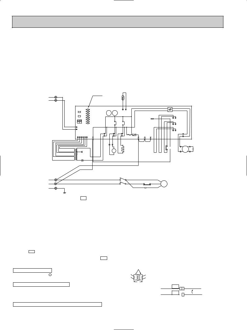
MODELS : PU18EK
SYMBOL |
NAME |
SYMBOL |
NAME |
SYMBOL |
NAME |
|
|
|
|
|
|
|
|
C |
COMPRESSOR CAPACITOR |
LD1 ~ LD8 |
LED <CHECK, SERVICE> |
TH3 |
OUTDOOR COIL THERMISTOR |
|
|
|
|
|
|
|
|
C3 |
FAN CAPACITOR |
MC |
COMPRESSOR |
X11 <O. B> |
CRANKCASE HEATER RELAY |
|
|
|
|
|
|
|
|
CH |
CRANKCASE HEATER |
MF3 |
OUTDOOR FAN MOTOR (INNER THERMOSTAT) |
X12 <O. B> |
COMPRESSOR RELAY |
|
|
|
|
|
|
|
|
CN3<O. B> |
CONNECTING WIRES INDOOR/OUTDOOR |
O. B |
OUTDOOR CONTROLLER BOARD |
ZNR <O. B> |
VARISTOR |
|
CONNECTOR |
SW1, 2, 3<O. B> |
SELECT SWITCH <CHECK, SERVICE> |
52C |
CONTACTOR |
||
|
||||||
|
|
|
|
|
|
|
CN6T<O. B> |
TRANSFORMER CONNECTOR |
T |
TRANSFORMER |
63H2 |
HIGH PRESSURE SWITCH <PROTECT> |
|
|
|
|
|
|
|
|
|
|
FC <O. B> |
FAN CONTROLLER |
TB1 |
POWER SUPPLY TERMINAL BLOCK |
|
|
|
|
|
|
|
|
|
|
F3 <O. B> |
FUSE <6A> |
TB3 |
CONNECTING WIRES INDOOR/OUTDOOR |
|
|
|
|
|
TERMINAL BLOCK |
||
|
|
|
|
|
||
|
|
|
|
|
|
|
|
|
|
|
51C |
OVERCURRENT RELAY |
|
|
|
|
|
|
|
FROM INDOOR UNIT CONNECTING WIRES 12V DC (polar)
POWER SUPPLY 208/230V 1phase 60Hz
1 |
YLW |
|
|
|
|
|
|
|
|
LED |
|
|
|
|
|
|
|
|
|
|
|
|
|
|
|
|
|
|
|
|
|
|
|
|
|
|
TH3 |
|
|
|
|
|
|
|
|
|
|
|
|
|
|||
2 |
ORN |
|
|
|
|
|
|
|
|
|
|
|
|
|
|
|
|
|
|
|
|
|
|
|
||
|
|
|
|
|
|
|
|
|
|
|
|
|
|
|
|
|
|
|
|
|
|
|
|
|
||
TB3 |
|
|
O.B |
|
|
|
|
|
|
|
|
|
|
|
|
|
|
|
|
|
|
|
|
|
|
|
|
|
|
|
|
|
|
|
|
|
|
|
|
|
|
|
|
|
|
|
|
|
|
|
|
||
|
|
|
SW1 |
|
|
|
LD8 |
|
|
|
|
|
|
|
|
|
|
|
|
|
|
|
|
|
||
|
|
|
|
|
|
|
|
|
LD7 |
X12 |
X11 |
|
CN2 |
|
|
|
|
|
|
|
FC |
|
|
|
||
|
|
|
SW2 |
|
|
|
LD6 |
|
|
|
|
|
|
|
|
|
|
|
|
|
||||||
|
|
|
|
|
|
LD5 |
|
|
|
|
|
|
|
|
|
|
|
|
|
|
|
|
|
|||
|
|
|
|
|
|
|
|
|
|
|
|
|
|
|
|
|
|
5 |
|
|
|
|
|
|
|
|
|
|
|
SW3 |
|
|
|
LD4 |
|
|
|
|
|
|
|
|
|
|
|
|
|
|
|
|
|||
|
|
|
|
|
|
LD3 |
|
|
|
|
|
|
|
|
|
|
|
|
|
|
26C |
|
|
|||
|
|
|
|
|
|
OFF |
|
|
|
|
|
|
|
|
|
|
|
|
|
|
|
|
|
|||
|
|
|
|
|
|
|
LD2 |
|
|
|
|
|
|
|
|
|
|
|
|
|
|
|
|
|
||
|
|
|
|
|
|
ON |
|
|
|
|
X12 |
|
X11 |
|
|
|
|
|
|
|
|
|
|
|
||
|
|
|
|
|
|
|
|
LD1 |
|
|
|
|
|
|
|
|
|
|
|
|
|
|
||||
|
|
|
2 |
|
1 |
|
|
|
|
|
|
|
|
|
|
|
|
|
|
63H2 |
|
|
||||
|
|
|
2 |
|
|
|
|
|
|
|
|
|
|
|
|
|
|
|
|
|
|
|
|
|
|
|
|
|
|
1 CN3 |
|
|
|
|
|
|
|
|
|
|
|
|
|
|
|
|
|
|
|
|
|||
|
|
|
|
|
CN6T |
|
|
|
|
|
|
|
|
F3 |
|
|
|
|
|
|
|
51CM |
|
|
||
|
|
|
|
|
|
|
|
|
|
|
|
|
|
|
|
|
|
|
|
|
|
|
|
|||
|
|
|
6 |
5 |
4 |
3 |
2 |
1 |
4 |
TRF |
|
52C |
|
CH |
ZNR |
R/1 |
S/2 |
T/3 |
|
|
|
|
|
|
|
|
|
|
|
|
|
|
|
|
|
|
|
|
|
|
|
|
|
|
MF3 |
|
|||||||
|
|
|
|
|
|
|
|
|
|
|
|
|
|
|
|
|
|
|
|
|||||||
|
|
|
|
|
|
|
|
|
|
GRY |
GRY |
WHT |
WHT |
|
|
BLU |
BLU |
YLM YLM |
YLM |
YLM |
RED RED |
BLU |
BLU |
WHT |
|
|
|
|
|
|
|
|
|
|
|
|
|
|
S |
|
|
|
|
|
|
|
|
|
|
|
|||
|
|
|
|
|
|
|
|
|
|
|
|
|
|
|
|
|
|
|
|
|
|
|
|
|
RED |
|
|
|
|
|
|
|
|
|
|
|
|
|
A |
|
|
|
|
|
|
|
|
|
|
|
|
|
|
|
|
|
|
|
|
|
|
|
|
|
|
|
|
|
|
|
|
|
|
|
|
63H2 |
|
|
||
|
|
|
|
|
|
|
|
|
|
|
|
|
|
CH |
|
|
|
|
|
|
|
MF3 |
C3 |
|||
|
BRN |
11.5V AC |
RED |
|
|
|
|
|
|
52C |
|
|
|
|
|
|
|
|
|
|
||||||
|
208V |
|
|
|
|
|
|
|
|
|
|
|
|
|
|
|
|
|
||||||||
|
|
|
|
|
|
|
|
|
|
|
|
|
|
|
|
|
|
|
|
|
|
|
ORN |
|||
|
|
|
|
|
|
|
|
|
|
|
|
B |
|
|
|
|
|
|
|
|
|
|
|
|
|
|
|
RED |
15.5V AC |
|
|
|
|
|
|
|
WHT |
|
|
|
|
|
|
|
|
|
|
|
|
|
|
|
|
|
|
|
ORN |
|
|
|
|
|
|
|
|
|
|
|
|
|
|
|
|
|
|
|
|
|||
|
ORN |
36.0V AC |
|
|
|
|
WHT |
|
|
|
|
|
|
|
|
|
|
|
|
|
|
|
|
|||
|
|
|
|
|
|
|
|
|
|
|
|
|
|
|
|
|
|
|
|
|
|
|
|
|||
|
|
|
T |
|
|
230V |
|
|
|
|
|
|
|
|
|
|
|
|
|
|
|
|
|
|
||
|
|
|
|
|
|
|
|
|
|
|
|
|
|
|
|
|
|
|
|
|
|
|
|
|
|
|
|
|
|
|
|
RED |
|
|
|
|
|
|
|
|
|
|
|
|
|
|
|
|
|
|
|
||
|
|
|
|
|
WHT |
|
|
|
|
|
|
|
|
|
|
|
|
|
|
|
|
|
|
|
||
TB1 |
|
|
|
|
|
|
|
|
|
|
|
|
52C |
|
|
|
|
|
|
|
|
|
|
|
|
|
|
|
|
|
|
|
|
|
|
|
|
|
|
|
|
|
|
|
|
|
|
|
|
|
|
|
|
L1 |
|
|
|
|
RED |
|
|
|
|
R |
|
|
U |
BLU |
|
|
|
|
R |
|
|
|
|
|
||
|
|
|
|
|
|
|
|
|
|
|
|
|
|
|
|
|
|
|
|
|
|
|
|
|
|
|
L2 |
|
|
|
|
WHT |
|
|
|
|
|
|
|
|
WHT |
2 51C 1 |
WHT |
|
C |
MC |
|
|
|
|
|||
|
|
|
|
|
|
|
|
|
|
|
|
T |
|
|
W |
|
|
|
|
|
|
|
|
|
|
|
GR |
|
|
|
|
|
|
|
|
|
|
|
|
|
BLU |
|
|
RED |
|
S |
|
|
|
|
|
||
|
|
|
|
|
|
|
|
|
|
|
|
|
|
|
|
|
|
|
|
|
|
|
||||
|
|
GRN |
|
|
|
|
|
|
|
|
|
|
|
|
|
|
|
C |
|
|
|
|
|
|
|
|
|
|
|
|
|
|
|
|
|
|
|
|
|
|
|
|
|
|
|
|
|
|
|
|
|
|
|
Main functions of LED (when both No. 1 and 2 of €SW3 are ¨OFF¨)
LED NO. |
Output display (light) |
Check display (flush) |
LD1 |
Compressor indoor command |
— |
LD2 |
— |
— |
|
|
|
LD3 |
— |
Pipe temperature sensor short / open |
|
|
|
LD4 |
Compressor ON |
63H2 functions |
|
|
|
LD5 |
Outdoor fan ON |
— |
|
|
|
LD6 |
— |
— |
|
|
|
LD7 |
— |
TH3 overheat protection |
|
|
|
LD8 |
Crankcase heater ON |
Defective input |
|
|
|
NOTES :If the operation stops to function of the protection device, the check display flashes.
How to use SW1 and 2
●Pressing SW1€ erases the past check contents loaded on the microcomputer.
●The output display (light) remains during operation but pressing SW2€ displays the past check contents in flashing mode. Pressing the switch again returns to output display (light).
 White connector
CAUTION FOR SERVICING
● s ⁄ı
The connector marked— — is to turn the compressor ON-OFF during servicing. The compressor stops by disconnecting the white connector as shown at the right.
CAUTION FOR POWER SUPPLY WIRING
●Since LD8 lights when normal power is turned "ON", check the power supply with the "ON" or "OFF" LD8.
Since the indoor transformer (T) is connected with 230V power, if 208V power is used, change the wiring connection in the following Procedure.
CAUTION FOR INDOOR AND OUTDOOR CONNECTING WIRES
 When power Supply is 208V
RED |
208V |
WHITE |
ORANGE |
230V |
|
● Since the indoor and outdoor connecting wires has polarity, make sure to connect the same terminal numbers (1, 2) for indoor and outdoor units.
14
 Loading...