


PUHY-(E)P200
Mitsubishi PUHY-(E)P200, PUHY-P250, PUHY-(E)P300, PUHY-P350, PUHY-(E)P400 SERVICE MANUAL
...
AIR CONDITIONERS
Models
PUHY-(E)P200, P250, (E)P300, P350, (E)P400, (E)P450YHM-A
PUHY-(E)P500, (E)P550, (E)P600, (E)P650YSHM-A
PUHY-(E)P700, (E)P750, (E)P800, (E)P850, (E)P900YSHM-A
PUHY-P950, P1000, P1050, P1100, P1150, P1200, P1250YSHM-A
Service Handbook
Safety Precautions
Before installing the unit, thoroughly read the following safety precautions.
Observe these safety precautions for your safety.
WARNING
This symbol is intended to alert the user to the presence of important instructions that must be followed to avoid
the risk of serious injury or death.
CAUTION
This symbol is intended to alert the user to the presence of important instructions that must be followed to avoid
the risk of serious injury or damage to the unit.
After reading this manual, give it to the user to retain for future reference.
Keep this manual for easy reference. When the unit is moved or repaired, give this manual to those who provide these
services.
When the user changes, make sure that the new user receives this manual.
WARNING
Ask your dealer or a qualified technician to install the
unit.
Improper installation by the user may result in water leakage, electric shock, smoke, and/or fire.
Properly install the unit on a surface that can withstand the weight of the unit.
Unit installed on an unstable surface may fall and cause injury.
Only use specified cables. Securely connect each cable so that the terminals do not carry the weight of the
cable.
Improperly connected or fixed cables may produce heat
and start a fire.
Take appropriate safety measures against strong
winds and earthquakes to prevent the unit from falling.
If the unit is not installed properly, the unit may fall and
cause serious injury to the person or damage to the unit.
Do not make any modifications or alterations to the
unit. Consult your dealer for repair.
Improper repair may result in water leakage, electric shock,
smoke, and/or fire.
In the event of a refrigerant leak, thoroughly ventilate
the room.
If refrigerant gas leaks and comes in contact with an open
flame, poisonous gases will be produced.
When installing the All-Fresh type units, take it into
consideration that the outside air may be discharged
directly into the room when the thermo is turned off.
Direct exposure to outdoor air may have an adverse effect
on health. It may also result in food spoilage.
Properly install the unit according to the instructions
in the installation manual.
Improper installation may result in water leakage, electric
shock, smoke, and/or fire.
Have all electrical work performed by an authorized
electrician according to the local regulations and instructions in this manual, and a dedicated circuit must
be used.
Insufficient capacity of the power supply circuit or improper
installation may result in malfunctions of the unit, electric
shock, smoke, and/or fire.
Do not touch the heat exchanger fins.
The fins are sharp and dangerous.
HWE07010 GB
ii
WARNING
Securely attach the terminal block cover (panel) to the
unit.
If the terminal block cover (panel) is not installed properly,
dust and/or water may infiltrate and pose a risk of electric
shock, smoke, and/or fire.
Only use the type of refrigerant that is indicated on the
unit when installing or reinstalling the unit.
Infiltration of any other type of refrigerant or air into the unit
may adversely affect the refrigerant cycle and may cause
the pipes to burst or explode.
When installing the unit in a small room, exercise caution and take measures against leaked refrigerant
reaching the limiting concentration.
Consult your dealer with any questions regarding limiting
concentrations and for precautionary measures before installing the unit. Leaked refrigerant gas exceeding the limiting concentration causes oxygen deficiency.
Consult your dealer or a specialist when moving or reinstalling the unit.
Improper installation may result in water leakage, electric
shock, and/or fire.
After completing the service work, check for a gas
leak.
If leaked refrigerant is exposed to a heat source, such as a
fan heater, stove, or electric grill, poisonous gases may be
produced.
Do not try to defeat the safety features of the unit.
Forced operation of the pressure switch or the temperature
switch by defeating the safety features of these devices, or
the use of accessories other than the ones that are recommended by MITSUBISHI may result in smoke, fire, and/or
explosion.
Only use accessories recommended by MITSUBISHI.
Ask a qualified technician to install the unit. Improper installation by the user may result in water leakage, electric
shock, smoke, and/or fire.
Control box houses high-voltage parts.
When opening or closing the front panel of the control box,
do not let it come into contact with any of the internal components. Before inspecting the inside of the control box,
turn off the power, keep the unit off for at least 10 minutes,
and confirm that the voltage between FT-P and FT-N on
INV Board has dropped to DC20V or less. (It takes about
10 minutes to discharge electricity after the power supply is
turned off.)
HWE07010 GB
ii
Precautions for handling units for use with R410A
CAUTION
Do not use the existing refrigerant piping.
A large amount of chlorine that may be contained in the re-
sidual refrigerant and refrigerating machine oil in the existing piping may cause the refrigerating machine oil in the
new unit to deteriorate.
R410A is a high-pressure refrigerant and can cause the
existing pipes to burst.
Use refrigerant pipes made of phosphorus deoxidized
copper. Keep the inner and outer surfaces of the pipes
clean and free of such contaminants as sulfur, oxides,
dust, dirt, shaving particles, oil, and water.
These types of contaminants inside the refrigerant pipes
may cause the refrigerant oil to deteriorate.
Store the pipes to be installed indoors, and keep both
ends of the pipes sealed until immediately before brazing. (Keep elbows and other joints wrapped in plastic.)
Infiltration of dust, dirt, or water into the refrigerant system
may cause the refrigerating machine oil to deteriorate or
cause the unit to malfunction.
Use a small amount of ester oil, ether oil, or alkylbenzene to coat flares and flanges.
Infiltration of a large amount of mineral oil may cause the refrigerating machine oil to deteriorate.
Charge liquid refrigerant (as opposed to gaseous refrigerant) into the system.
If gaseous refrigerant is charged into the system, the composition of the refrigerant in the cylinder will change and
may result in performance loss.
Use a vacuum pump with a reverse-flow check valve.
If a vacuum pump that is not equipped with a reverse-flow
check valve is used, the vacuum pump oil may flow into the
refrigerant cycle and cause the refrigerating machine oil to
deteriorate.
Prepare tools for exclusive use with R410A. Do not use
the following tools if they have been used with the conventional refrigerant (gauge manifold, charging hose,
gas leak detector, reverse-flow check valve, refrigerant
charge base, vacuum gauge, and refrigerant recovery
equipment.).
If the refrigerant or the refrigerating machine oil left on
these tools are mixed in with R410A, it may cause the refrigerating machine oil to deteriorate.
Infiltration of water may cause the refrigerating machine
oil to deteriorate.
Gas leak detectors for conventional refrigerants will not
detect an R410A leak because R410A is free of chlorine.
Do not use a charging cylinder.
If a charging cylinder is used, the composition of the refrigerant will change, and the unit may experience power loss.
Exercise special care when handling the tools for use
with R410A.
Infiltration of dust, dirt, or water into the refrigerant system
may cause the refrigerating machine oil to deteriorate.
Only use refrigerant R410A.
The use of other types of refrigerant that contain chlorine
(i.e. R22) may cause the refrigerating machine oil to deteriorate.
HWE07010 GB
iiiiii

Before installing the unit
WARNING
Do not install the unit where a gas leak may occur.
If gaseous refrigerant leaks and piles up around the unit, it
may be ignited.
Do not use the unit to keep food items, animals, plants,
artifacts, or for other special purposes.
The unit is not designed to preserve food products.
Do not use the unit in an unusual environment.
Do not install the unit where a large amount of oil or steam
is present or where acidic or alkaline solutions or chemical
sprays are used frequently. Doing so may lead to a remarkable drop in performance, electric shock, malfunctions, smoke, and/or fire.
The presence of organic solvents or corrosive gas (i.e.
ammonia, sulfur compounds, and acid) may cause gas
leakage or water leakage.
When installing the unit in a hospital, take appropriate
measures to reduce noise interference.
High-frequency medical equipment may interfere with the
normal operation of the air conditioner or vice versa.
Do not install the unit on or over things that cannot get
wet.
When the humidity level exceeds 80% or if the drainage
system is clogged, the indoor unit may drip water. Drain water is also discharged from the outdoor unit. Install a centralized drainage system if necessary.
HWE07010 GB
iv
Before installing the unit (moving and reinstalling the unit) and performing
electrical work
CAUTION
Properly ground the unit.
Do not connect the grounding wire to a gas pipe, water pipe,
lightning rod, or grounding wire from a telephone pole. Improper grounding may result in electric shock, smoke, fire,
and/or malfunction due to noise interference.
Do not put tension on the power supply wires.
If tension is put on the wires, they may break and result in
excessive heat, smoke, and/or fire.
Install an earth leakage breaker to avoid the risk of
electric shock.
Failure to install an earth leakage breaker may result in
electric shock, smoke, and/or fire.
Use the kind of power supply wires that are specified
in the installation manual.
The use of wrong kind of power supply wires may result in
current leak, electric shock, and/or fire.
Use breakers and fuses (current breaker, remote
switch <switch + Type-B fuse>, moulded case circuit
breaker) with the proper current capacity.
The use of wrong capacity fuses, steel wires, or copper
wires may result in malfunctions, smoke, and/or fire.
Periodically check the installation base for damage.
If the unit is left on a damaged platform, it may fall and
cause injury.
Properly install the drain pipes according to the instructions in the installation manual. Keep them insulated to avoid dew condensation.
Improper plumbing work may result in water leakage and
damage to the furnishings.
Exercise caution when transporting products.
Products weighing more than 20 kg should not be carried
alone.
Do not carry the product by the PP bands that are used on
some products.
Do not touch the heat exchanger fins. They are sharp and
dangerous.
When lifting the unit with a crane, secure all four corners
to prevent the unit from falling.
Properly dispose of the packing materials.
Nails and wood pieces in the package may pose a risk of
injury.
Plastic bags may pose a risk of choking hazard to chil-
dren. Tear plastic bags into pieces before disposing of
them.
Do not spray water on the air conditioner or immerse
the air conditioner in water.
Otherwise, electric shock and/or fire may result.
When handling units, always wear protective gloves to
protect your hands from metal parts and high-temperature parts.
HWE07010 GB
vv
Before the test run
CAUTION
Turn on the unit at least 12 hours before the test run.
Keep the unit turned on throughout the season. If the unit is
turned off in the middle of a season, it may result in malfunctions.
To avoid the risk of electric shock or malfunction of the
unit, do not operate switches with wet hands.
Do not touch the refrigerant pipes with bare hands during and immediately after operation.
During or immediately after operation, certain parts of the
unit such as pipes and compressor may be either very cold
or hot, depending on the state of the refrigerant in the unit
at the time. To reduce the risk of frost bites and burns, do
not touch these parts with bare hands.
Do not operate the unit without panels and safety
guards.
Rotating, high-temperature, or high-voltage parts on the unit
pose a risk of burns and/or electric shock.
Do not turn off the power immediately after stopping
the operation.
Keep the unit on for at least five minutes before turning off
the power to prevent water leakage or malfunction.
Do not operate the unit without the air filter.
Dust particles may build up in the system and cause malfunctions.
HWE07010 GB
vi

CONTENTS
I Read Before Servicing
[1] Read Before Servicing.............................................................................................................. 3
[2] Necessary Tools and Materials ................................................................................................ 4
[3] Piping Materials ........................................................................................................................ 5
[4] Storage of Piping ...................................................................................................................... 7
[5] Pipe Processing........................................................................................................................ 7
[6] Brazing...................................................................................................................................... 8
[7] Air Tightness Test..................................................................................................................... 9
[8] Vacuum Drying (Evacuation) ..................................................................................................10
[9] Refrigerant Charging .............................................................................................................. 11
[10] Remedies to be taken in case of a Refrigerant Leak............................................................ 11
[11] Characteristics of the Conventional and the New Refrigerants ............................................ 12
[12] Notes on Refrigerating Machine Oil...................................................................................... 13
II Restrictions
[1] System configuration .............................................................................................................. 17
[2] Types and Maximum allowable Length of Cables .................................................................. 19
[3] Switch Settings and Address Settings .................................................................................... 20
[4] Sample System Connection ................................................................................................... 27
[5] An Example of a System to which an MA Remote Controller is connected ........................... 28
[6] An Example of a System to which an M-NET Remote Controller is connected ..................... 38
[7] An Example of a System to which both MA Remote Controller and
M-NET Remote Controller are connected .............................................................................. 40
[8] Restrictions on Pipe Length.................................................................................................... 42
III Outdoor Unit Components
[1] Outdoor Unit Components and Refrigerant Circuit ................................................................. 49
[2] Control Box of the Outdoor Unit.............................................................................................. 51
[3] Outdoor Unit Circuit Board...................................................................................................... 52
IV Remote Controller
[1] Functions and Specifications of MA and ME Remote Controllers .......................................... 59
[2] Group Settings and Interlock Settings via the ME Remote Controller .................................... 60
[3] Interlock Settings via the MA Remote Controller .................................................................... 64
[4] Using the built-in Temperature Sensor on the Remote Controller.......................................... 65
V Electrical Wiring Diagram
[1] Electrical Wiring Diagram of the Outdoor Unit ........................................................................ 69
[2] Electrical Wiring Diagram of Transmission Booster................................................................ 70
VI Refrigerant Circuit
[1] Refrigerant Circuit Diagram .................................................................................................... 73
[2] Principal Parts and Functions ................................................................................................. 74
VII Control
[1] Functions and Factory Settings of the Dipswitches ................................................................ 81
[2] Controlling the Outdoor Unit ................................................................................................... 87
[3] Operation Flow Chart.............................................................................................................. 99
VIII Test Run Mode
[1] Items to be checked before a Test Run................................................................................ 107
[2] Test Run Method .................................................................................................................. 108
[3] Operating Characteristic and Refrigerant Amount................................................................ 109
[4] Adjusting the Refrigerant Amount......................................................................................... 109
[5] Refrigerant Amount Adjust Mode.......................................................................................... 112
[6] The following symptoms are normal. .................................................................................... 114
[7] Standard Operation Data (Reference Data) ......................................................................... 115
IX Troubleshooting
[1] Error Code Lists.................................................................................................................... 155
[2] Responding to Error Display on the Remote Controller........................................................ 158
[3] Investigation of Transmission Wave Shape/Noise ............................................................... 219
[4] Troubleshooting Principal Parts............................................................................................ 222
[5] Refrigerant Leak ................................................................................................................... 241
[6] Compressor Replacement Instructions................................................................................. 243
[7] Troubleshooting Using the Outdoor Unit LED Error Display................................................. 245
X LED Monitor Display on the Outdoor Unit Board
[1] How to Read the LED on the Service Monitor ...................................................................... 249
HWE07010 GB


I Read Before Servicing
[1] Read Before Servicing ....................................................................................................... 3
[2] Necessary Tools and Materials.......................................................................................... 4
[3] Piping Materials .................................................................................................................5
[4] Storage of Piping ............................................................................................................... 7
[5] Pipe Processing................................................................................................................. 7
[6] Brazing............................................................................................................................... 8
[7] Air Tightness Test.............................................................................................................. 9
[8] Vacuum Drying (Evacuation) ........................................................................................... 10
[9] Refrigerant Charging........................................................................................................ 11
[10] Remedies to be taken in case of a Refrigerant Leak ....................................................... 11
[11] Characteristics of the Conventional and the New Refrigerants ....................................... 12
[12] Notes on Refrigerating Machine Oil ................................................................................. 13
HWE07010 GB
- 1 -

- 2 -

[ I Read Before Servicing ]
I Read Before Servicing
[1] Read Before Servicing
1. Check the type of refrigerant used in the system to be serviced.
Refrigerant Type
Multi air conditioner for building application CITY MULTI YHM-A series R410A
2. Check the symptoms exhibited by the unit to be serviced.
Refer to this service handbook for symptoms relating to the refrigerant cycle.
3. Thoroughly read the safety precautions at the beginning of this manual.
4. Preparing necessary tools: Prepare a set of tools to be used exclusively with each type of refrigerant.
Refer to "Necessary Tools and Materials" for information on the use of tools.(page 4)
5. Verification of the connecting pipes: Verify the type of refrigerant used for the unit to be moved or replaced.
Use refrigerant pipes made of phosphorus deoxidized copper. Keep the inner and outer surfaces of the pipes clean and free
of such contaminants as sulfur, oxides, dust, dirt, shaving particles, oil, and water.
These types of contaminants inside the refrigerant pipes may cause the refrigerant oil to deteriorate.
6. If there is a leak of gaseous refrigerant and the remaining refrigerant is exposed to an open flame, a poisonous gas
hydrofluoric acid may form. Keep workplace well ventilated.
CAUTION
Install new pipes immediately after removing old ones to keep moisture out of the refrigerant circuit.
The use of refrigerant that contains chloride, such as R22, will cause the refrigerating machine oil to deteriorate.
HWE07010 GB
- 3 -
[ I Read Before Servicing ]
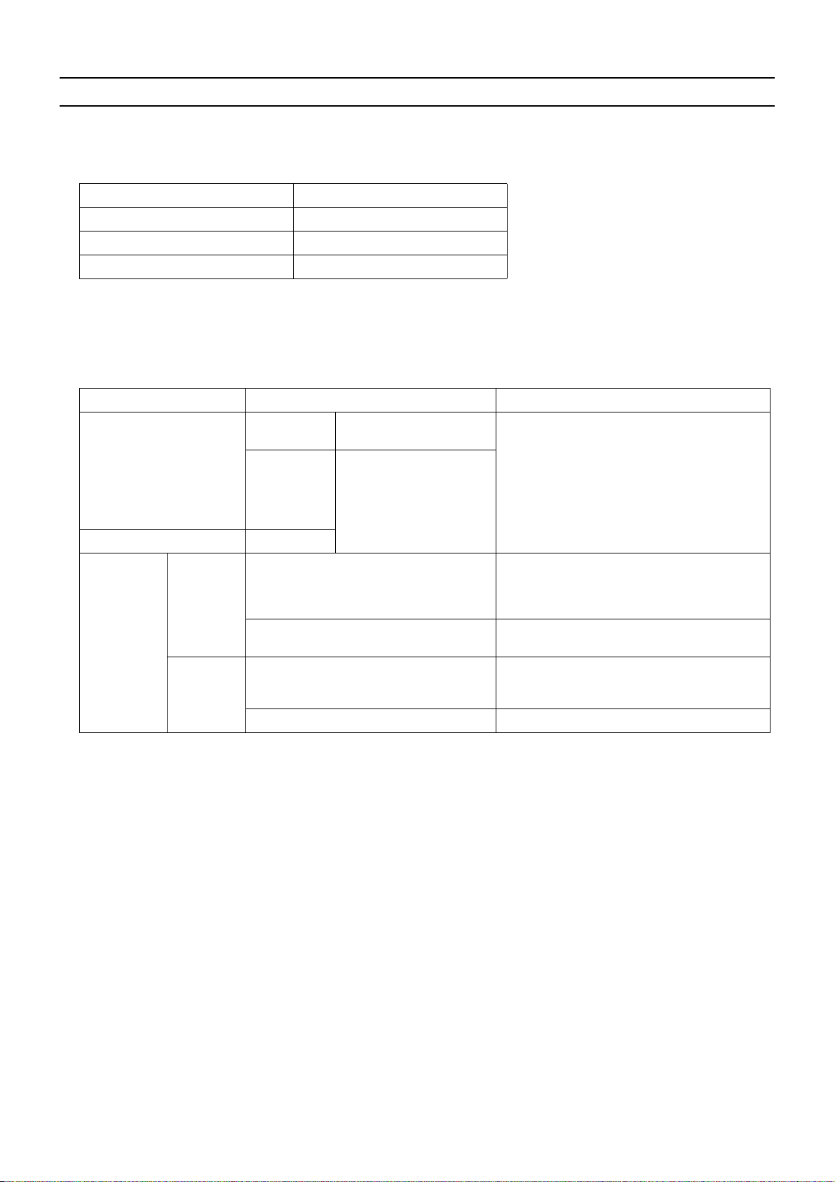
[2] Necessary Tools and Materials
Prepare the following tools and materials necessary for installing and servicing the unit.
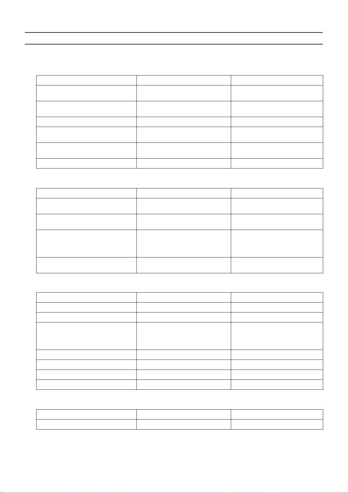
Tools for use with R410A (Adaptability of tools that are for use with R22 or R407C)
1. To be used exclusively with R410A (not to be used if used with R22 or R407C)
Tools/Materials Use Notes
Gauge Manifold Evacuation and refrigerant charging Higher than 5.09MPa[738psi] on the
high-pressure side
Charging Hose Evacuation and refrigerant charging The hose diameter is larger than the
conventional model.
Refrigerant Recovery Cylinder Refrigerant recovery
Refrigerant Cylinder Refrigerant charging The refrigerant type is indicated. The
cylinder is pink.
Charging Port on the Refrigerant Cylinder Refrigerant charging The charge port diameter is larger
than that of the current port.
Flare Nut Connection of the unit with the pipes Use Type-2 Flare nuts.
2. Tools and materials that may be used with R410A with some restrictions
Tools/Materials Use Notes
Gas Leak Detector Gas leak detection The ones for use with HFC refrigerant
may be used.
Vacuum Pump Vacuum drying May be used if a check valve adapter
is attached.
Flare Tool Flare processing Flare processing dimensions for the
piping in the system using the new refrigerant differ from those of R22. Refer to next page.
Refrigerant Recovery Equipment Refrigerant recovery May be used if compatible with
R410A.
3. Tools and materials that are used with R22 or R407C that may also be used with R410A
Tools/Materials Use Notes
Vacuum Pump with a Check Valve Vacuum drying
Bender Bending pipes
Torque Wrench Tightening flare nuts Only the flare processing dimensions
for pipes that have a diameter of
ø12.70 (1/2") and ø15.88 (5/8") have
been changed.
Pipe Cutter Cutting pipes
Welder and Nitrogen Cylinder Welding pipes
Refrigerant Charging Meter Refrigerant charging
Vacuum Gauge Vacuum level check
4. Tools and materials that must not be used with R410A
Tools/Materials Use Notes
Charging Cylinder Refrigerant charging Prohibited to use
Tools for R410A must be handled with special care to keep moisture and dust from infiltrating the cycle.
HWE07010 GB
- 4 -
[ I Read Before Servicing ]
[3] Piping Materials
Do not use the existing piping!
1. Copper pipe materials
O-material (Annealed) Soft copper pipes (annealed copper pipes). They can easily be bent with hands.
1/2H-material (Drawn) Hard copper pipes (straight pipes). They are stronger than the O-material (Annealed)
at the same radial thickness.
The distinction between O-materials (Annealed) and 1/2H-materials (Drawn) is made based on the strength of the pipes them-
selves.
O-materials (Annealed) can easily be bent with hands.
1/2H-materials (Drawn) are considerably stronger than O-material (Annealed) at the same thickness.
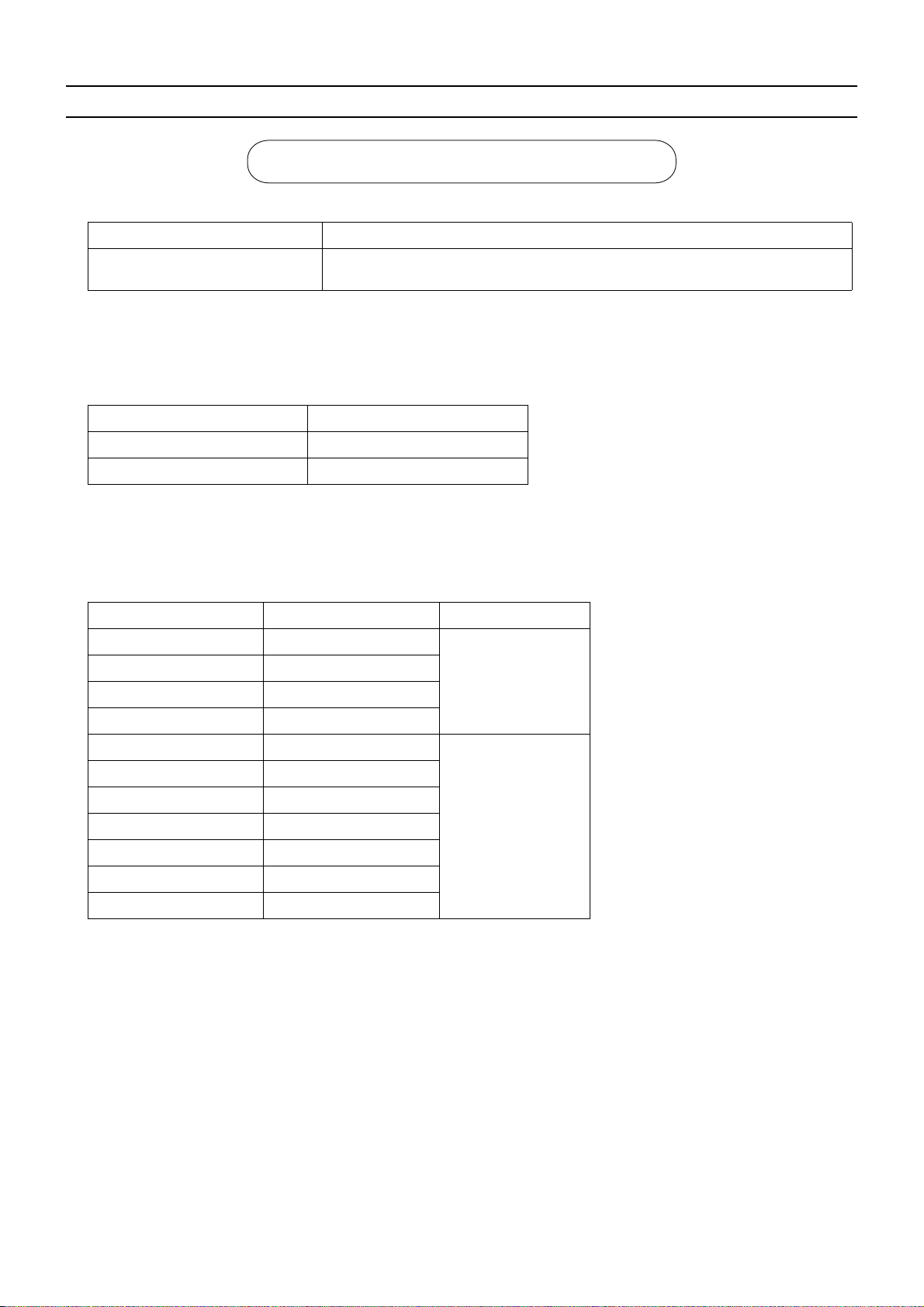
2. Types of copper pipes
Maximum working pressure Refrigerant type
3.45 MPa [500psi] R22, R407C etc.
4.30 MPa [624psi] R410A etc.
3. Piping materials/Radial thickness
Use refrigerant pipes made of phosphorus deoxidized copper.
The operation pressure of the units that use R410A is higher than that of the units that use R22.
Use pipes that have at least the radial thickness specified in the chart below.
(Pipes with a radial thickness of 0.7 mm or less may not be used.)
Pipe size (mm[in]) Radial thickness (mm) Type
ø6.35 [1/4"] 0.8t
ø9.52 [3/8"] 0.8t
ø12.7 [1/2"] 0.8t
ø15.88 [5/8"] 1.0t
ø19.05 [3/4"] 1.0t
ø22.2 [7/8"] 1.0t
ø25.4 [1"] 1.0t
ø28.58 [1-1/8"] 1.0t
ø31.75 [1-1/4"] 1.1t
ø34.93 [1-3/8"] 1.1t
ø41.28 [1-5/8"] 1.2t
The pipes in the system that uses the refrigerant currently on the market are made with O-material (Annealed), even if the
pipe diameter is less than ø19.05 (3/4"). For a system that uses R410A, use pipes that are made with 1/2H-material (Drawn)
unless the pipe diameter is at least ø19.05 (3/4") and the radial thickness is at least 1.2t.
The figures in the radial thickness column are based on the Japanese standards and provided only as a reference. Use pipes
that meet the local standards.
O-material (Annealed)
1/2H-material,
H-material (Drawn)
HWE07010 GB
- 5 -
[ I Read Before Servicing ]
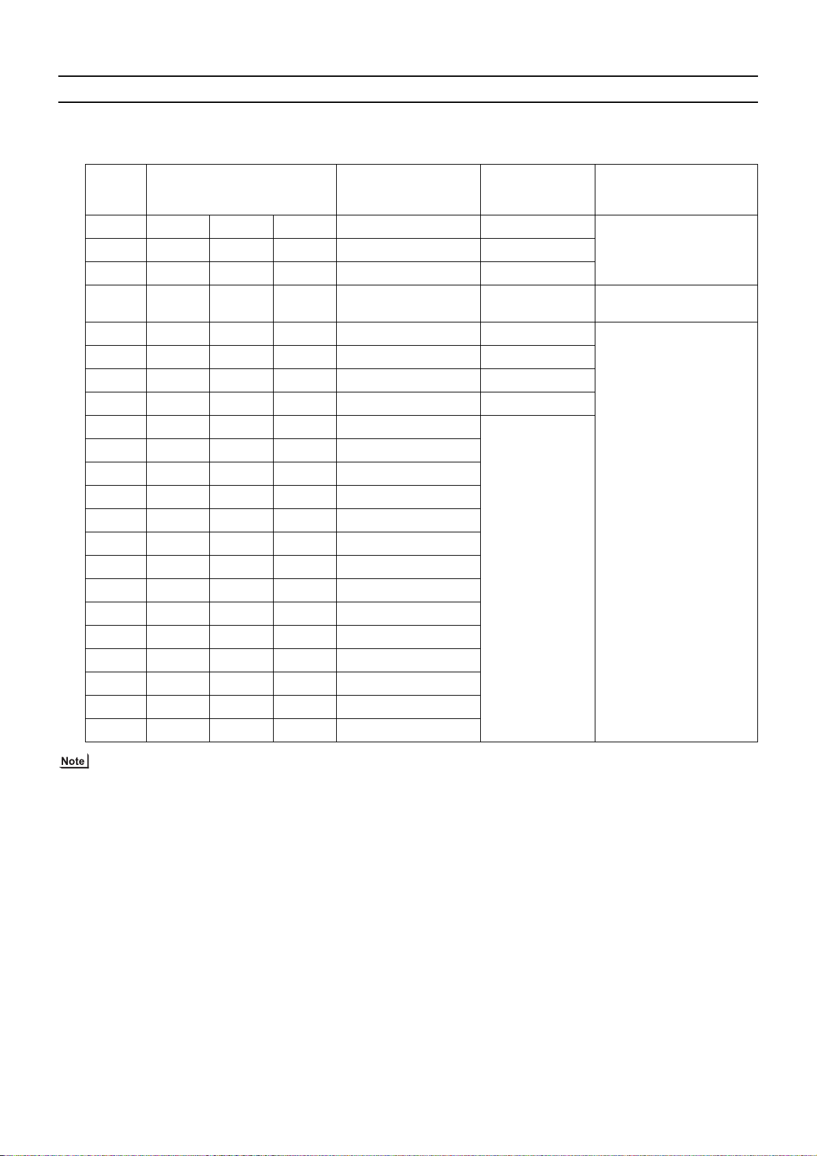
4. Thickness and refrigerant type indicated on the piping materials
Ask the pipe manufacturer for the symbols indicated on the piping material for new refrigerant.
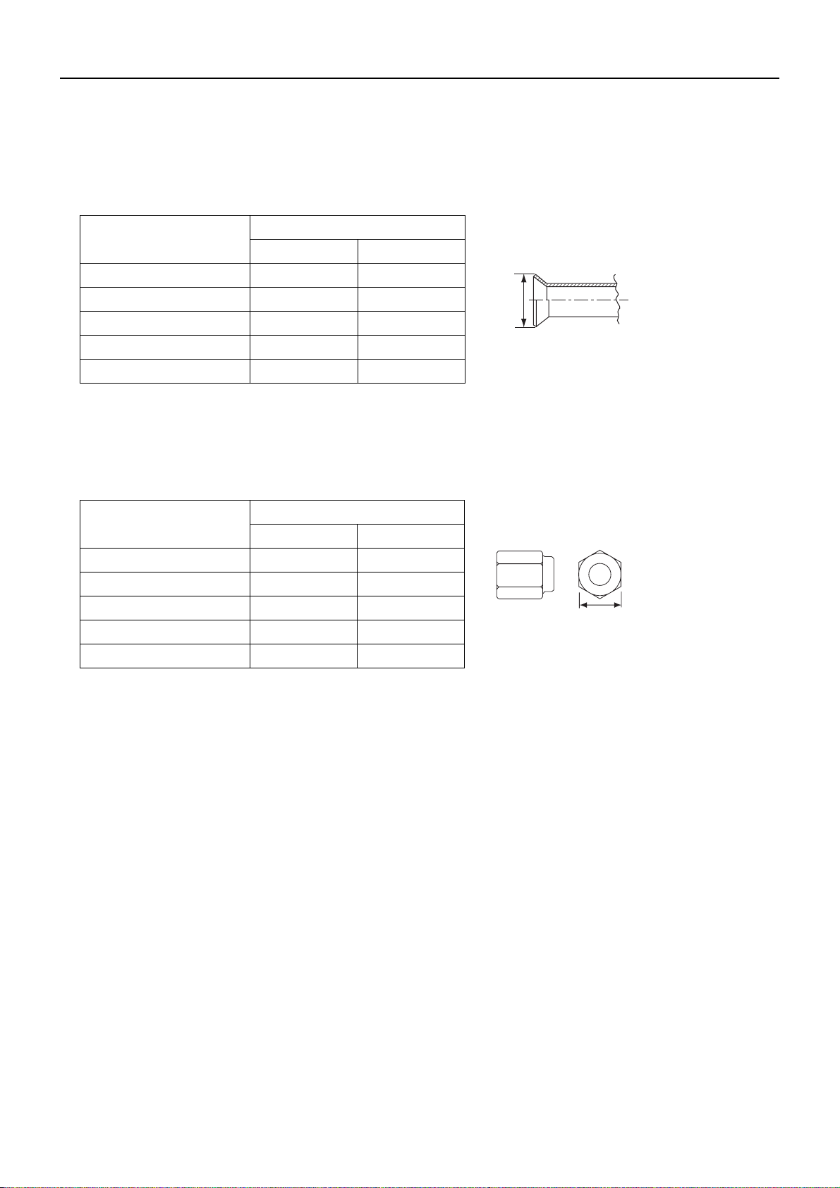
5. Flare processing (O-material (Annealed) and OL-material only)
The flare processing dimensions for the pipes that are used in the R410A system are larger than those in the R22 system.
Flare processing dimensions (mm[in])
A dimension (mm)
Pipe size (mm[in])
R410A R22, R407C
ø6.35 [1/4"] 9.1 9.0
ø9.52 [3/8"] 13.2 13.0
ø12.7 [1/2"] 16.6 16.2
Dimension A
ø15.88 [5/8"] 19.7 19.4
ø19.05 [3/4"] 24.0 23.3
If a clutch-type flare tool is used to flare the pipes in the system using R410A, the length of the pipes must be between 1.0
and 1.5 mm. For margin adjustment, a copper pipe gauge is necessary.
6. Flare nut
The flare nut type has been changed to increase the strength. The size of some of the flare nuts have also been changed.
Flare nut dimensions (mm[in])
B dimension (mm)
Pipe size (mm[in])
R410A R22, R407C
ø6.35 [1/4"] 17.0 17.0
ø9.52 [3/8"] 22.0 22.0
ø12.7 [1/2"] 26.0 24.0
Dimension B
ø15.88 [5/8"] 29.0 27.0
ø19.05 [3/4"] 36.0 36.0
The figures in the radial thickness column are based on the Japanese standards and provided only as a reference. Use pipes
that meet the local standards.
HWE07010 GB
- 6 -
[ I Read Before Servicing ]
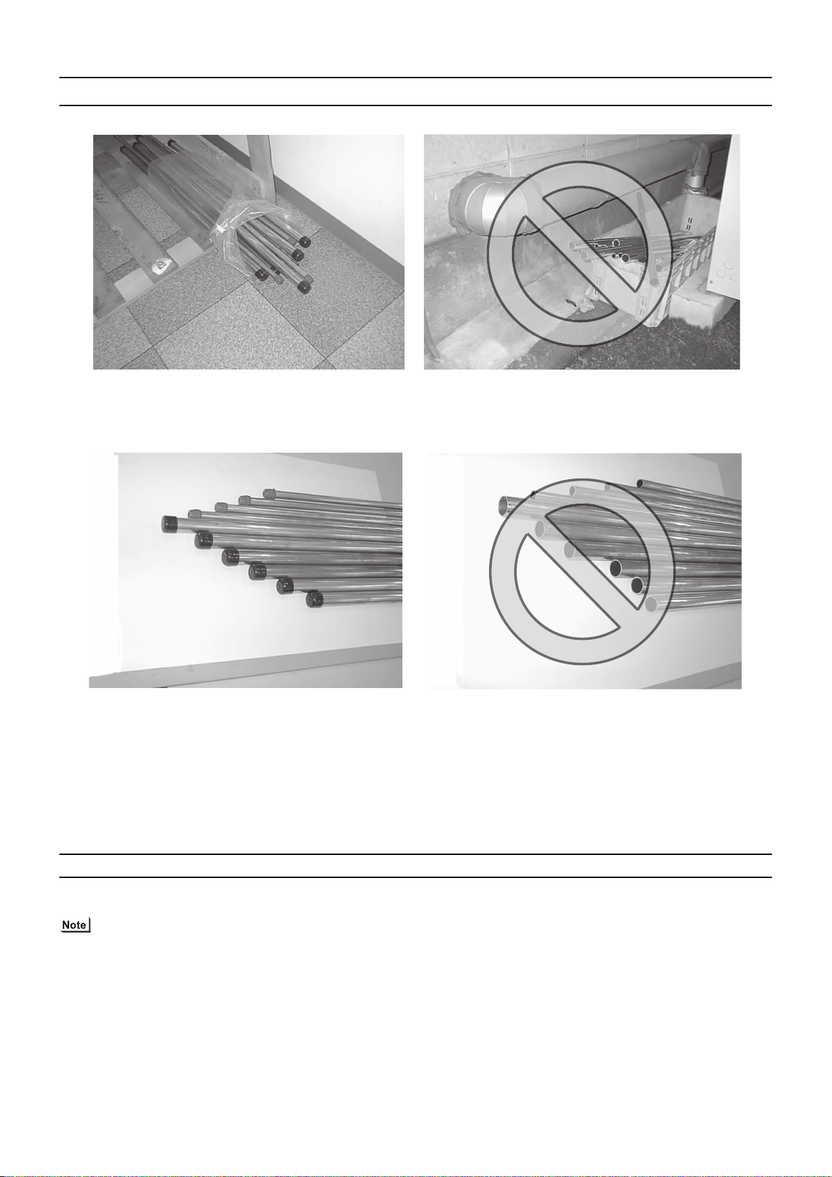
[4] Storage of Piping
1. Storage location
Store the pipes to be used indoors. (Warehouse at site or owner's warehouse)
If they are left outdoors, dust, dirt, or moisture may infiltrate and contaminate the pipe.
2. Sealing the pipe ends
Both ends of the pipes should be sealed until just before brazing.
Keep elbow pipes and T-joints in plastic bags.
The new refrigerator oil is 10 times as hygroscopic as the conventional refrigerating machine oil (such as Suniso) and, if not
handled with care, could easily introduce moisture into the system. Keep moisture out of the pipes, for it will cause the oil to
deteriorate and cause a compressor failure.
[5] Pipe Processing
Use a small amount of ester oil, ether oil, or alkylbenzene to coat flares and flanges.
Use a minimum amount of oil.
Use only ester oil, ether oil, and alkylbenzene.
HWE07010 GB
- 7 -
[ I Read Before Servicing ]
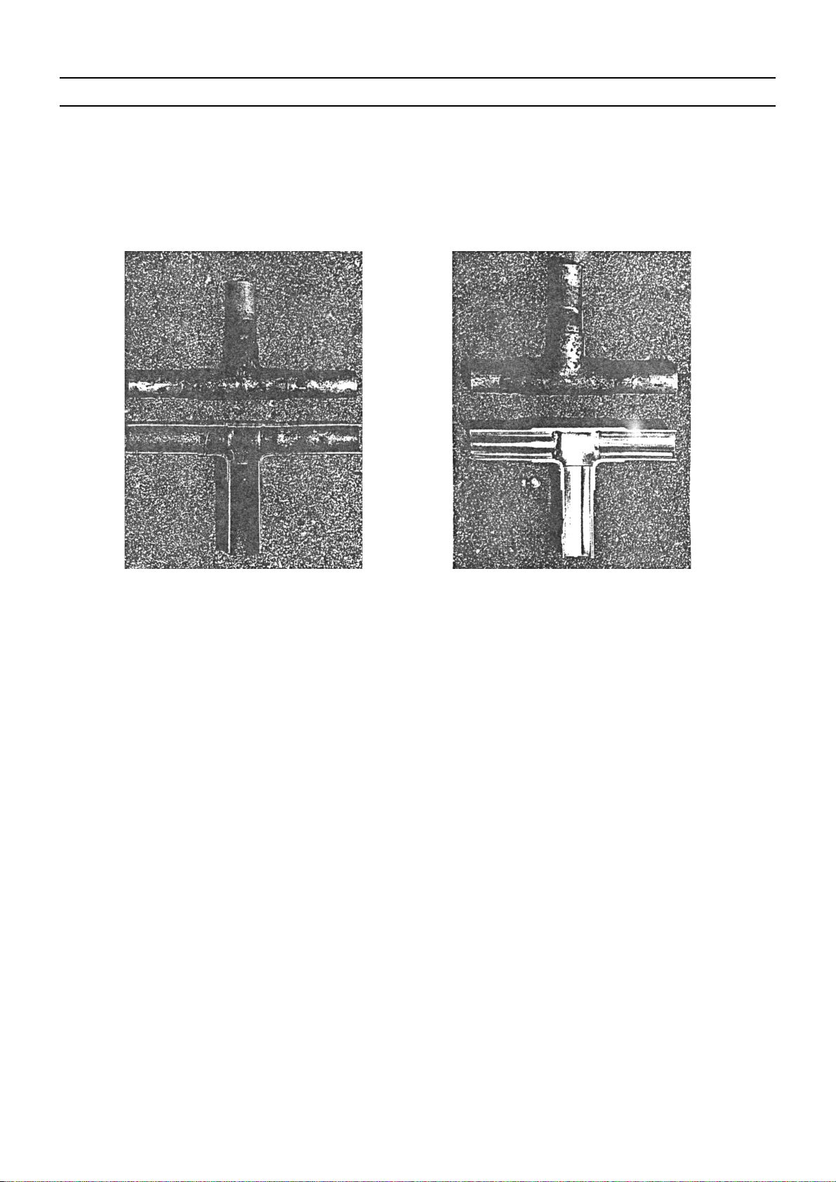
[6] Brazing
No changes have been made in the brazing procedures. Perform brazing with special care to keep foreign objects (such as oxide
scale, water, and dust) out of the refrigerant system.
Example: Inside the brazed connection
Use of oxidized solder for brazing Use of non-oxidized solder for brazing
1. Items to be strictly observed
Do not conduct refrigerant piping work outdoors if raining.
Use non-oxidized solder.
Use a brazing material (BCuP-3) that requires no flux when brazing between copper pipes or between a copper pipe and
copper coupling.
If installed refrigerant pipes are not immediately connected to the equipment, then braze and seal both ends.
2. Reasons
The new refrigerating machine oil is 10 times as hygroscopic as the conventional oil and is more likely to cause unit failure if
water infiltrates into the system.
Flux generally contains chloride. Residual flux in the refrigerant circuit will cause sludge to form.
3. Notes
Do not use commercially available antioxidants because they may cause the pipes to corrode or refrigerating machine oil to
deteriorate.
HWE07010 GB
- 8 -
[ I Read Before Servicing ]
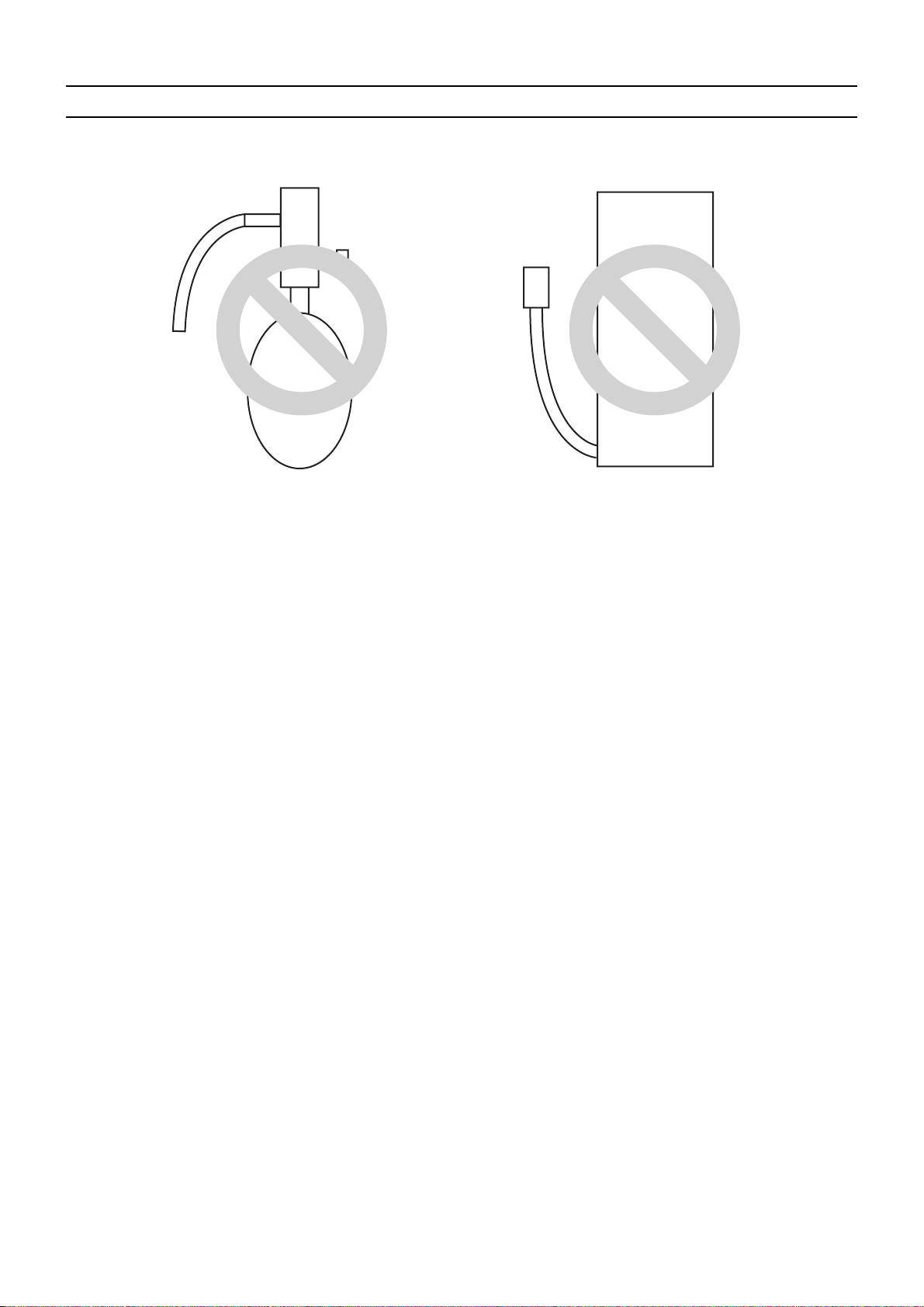
[7] Air Tightness Test
No changes have been made in the detection method. Note that a refrigerant leak detector for R22 will not detect an R410A leak.
Halide torch R22 leakage detector
1. Items to be strictly observed
Pressurize the equipment with nitrogen up to the design pressure (4.15MPa[601psi]), and then judge the equipment's air tight-
ness, taking temperature variations into account.
When using refrigerant instead of a leak detector to find the location of a leak, use R410A.
Refrigerant R410A must be charged in its liquid state (vs. gaseous state).
2. Reasons
Oxygen, if used for an air tightness test, poses a risk of explosion. (Only use nitrogen to check air tightness.)
Refrigerant R410A must be charged in its liquid state. If gaseous refrigerant in the cylinder is drawn out first, the composition
of the remaining refrigerant in the cylinder will change and become unsuitable for use.
3. Notes
Procure a leak detector that is specifically designed to detect an HFC leak. A leak detector for R22 will not detect an
HFC(R410A, R407C) leak.
HWE07010 GB
- 9 -
[ I Read Before Servicing ]
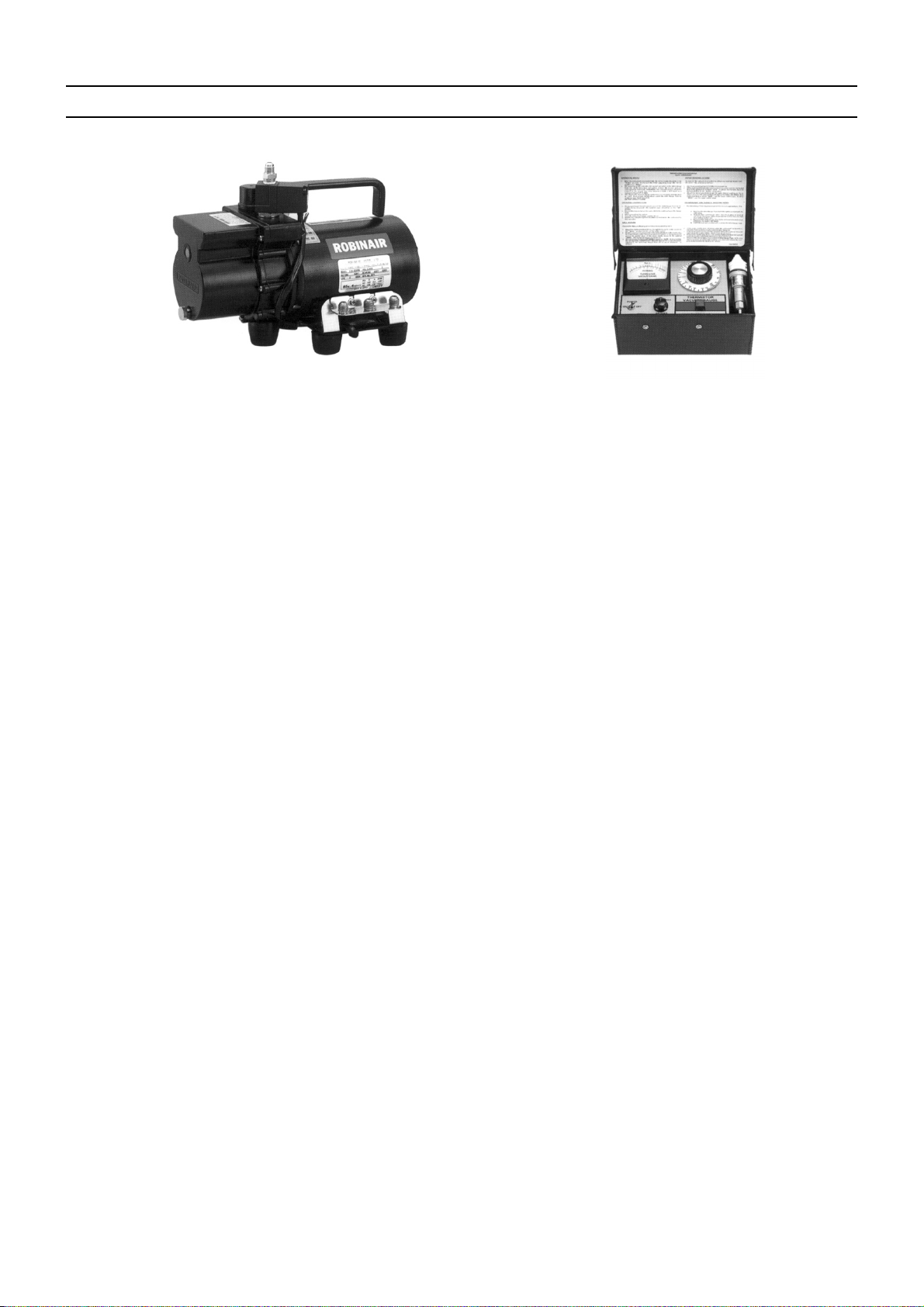
[8] Vacuum Drying (Evacuation)
(Photo1) 15010H (Photo2) 14010
Recommended vacuum gauge:
ROBINAIR 14010 Thermistor Vacuum Gauge
1. Vacuum pump with a reverse-flow check valve (Photo1)
To prevent the vacuum pump oil from flowing into the refrigerant circuit during power OFF or power failure, use a vacuum
pump with a reverse-flow check valve.
A reverse-flow check valve may also be added to the vacuum pump currently in use.
2. Standard of vacuum degree (Photo 2)
Use a vacuum pump that attains 0.5Torr(65Pa) or lower degree of vacuum after 5 minutes of operation, and connect it directly
to the vacuum gauge. Use a pump well-maintained with an appropriate lubricant. A poorly maintained vacuum pump may not
be able to attain the desired degree of vacuum.
3. Required precision of vacuum gauge
Use a vacuum gauge that registers a vacuum degree of 5Torr(650Pa) and measures at intervals of 1Torr(130Pa). (A recommended vacuum gauge is shown in Photo2.)
Do not use a commonly used gauge manifold because it cannot register a vacuum degree of 5Torr(650Pa).
4. Evacuation time
After the degree of vacuum has reached 5Torr(650Pa), evacuate for an additional 1 hour. (A thorough vacuum drying re-
moves moisture in the pipes.)
Verify that the vacuum degree has not risen by more than 1Torr(130Pa) 1hour after evacuation. A rise by less than
1Torr(130Pa) is acceptable.
If the vacuum is lost by more than 1Torr(130Pa), conduct evacuation, following the instructions in section 6. Special vacuum
drying.
5. Procedures for stopping vacuum pump
To prevent the reverse flow of vacuum pump oil, open the relief valve on the vacuum pump side, or draw in air by loosening
the charge hose, and then stop the operation.
The same procedures should be followed when stopping a vacuum pump with a reverse-flow check valve.
6. Special vacuum drying
When 5Torr(650Pa) or lower degree of vacuum cannot be attained after 3 hours of evacuation, it is likely that water has pen-
etrated the system or that there is a leak.
If water infiltrates the system, break the vacuum with nitrogen. Pressurize the system with nitrogen gas to
0.5kgf/cm
2
G(0.05MPa) and evacuate again. Repeat this cycle of pressurizing and evacuation either until the degree of vac-
uum below 5Torr(650Pa) is attained or until the pressure stops rising.
Only use nitrogen gas for vacuum breaking. (The use of oxygen may result in an explosion.)
HWE07010 GB
- 10 -
[ I Read Before Servicing ]
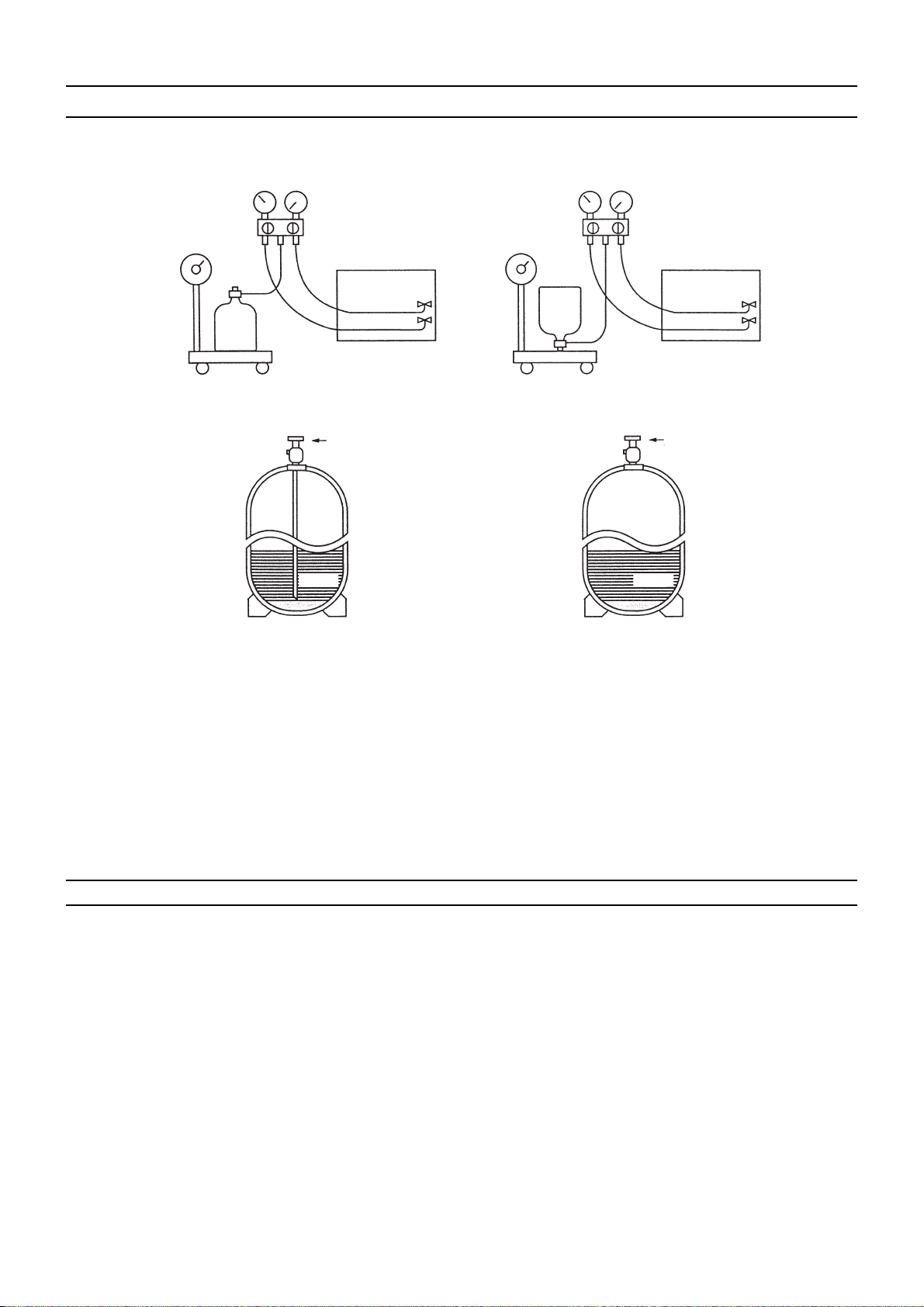
[9] Refrigerant Charging
Cylinder with a siphon
Cylinder without a siphon
Cylin-
Cylin-
der
der
Cylinder color R410A is pink. Refrigerant charging in the liquid state
Valve Valve
liquid
liquid
1. Reasons
R410A is a pseudo-azeotropic HFC blend (boiling point R32=-52°C[-62°F], R125=-49°C[-52°F]) and can almost be handled
the same way as a single refrigerant, such as R22. To be safe, however, draw out the refrigerant from the cylinder in the liquid
phase. If the refrigerant in the gaseous phase is drawn out, the composition of the remaining refrigerant will change and become unsuitable for use.
2. Notes
When using a cylinder with a siphon, refrigerant is charged in the liquid state without the need for turning it upside down. Check
the type of the cylinder on the label before use.
[10] Remedies to be taken in case of a Refrigerant Leak
If the refrigerant leaks out, it may be replenished. The entire refrigerant does not need to be replaced. (Charge refrigerant in the
liquid state.)
Refer to "IX [5] Refrigerant Leak".(page 241)
HWE07010 GB
- 11 -

[ I Read Before Servicing ]
[11] Characteristics of the Conventional and the New Refrigerants
1. Chemical property
As with R22, the new refrigerant (R410A) is low in toxicity and chemically stable nonflammable refrigerant.
However, because the specific gravity of vapor refrigerant is greater than that of air, leaked refrigerant in a closed room will
accumulate at the bottom of the room and may cause hypoxia.
If exposed to an open flame, refrigerant will generate poisonous gases. Do not perform installation or service work in a confined area.
New Refrigerant (HFC type) Conventional Refriger-
ant (HCFC type)
R410A R407C R22
R32/R125 R32/R125/R134a R22
Composition (wt%) (50/50) (23/25/52) (100)
Type of Refrigerant Pseudo-azeotropic
Refrigerant
Non-azeotropic
Refrigerant
Single Refrigerant
Chloride Not included Not included Included
Safety Class A1/A1 A1/A1 A1
Molecular Weight 72.6 86.2 86.5
Boiling Point (°C/°F) -51.4/-60.5 -43.6/-46.4 -40.8/-41.4
Steam Pressure
1.557/226 0.9177/133 0.94/136
(25°C,MPa/77°F,psi) (gauge)
Saturated Steam Density
(25°C,kg/m
3
/77°F,psi)
64.0 42.5 44.4
Flammability Nonflammable Nonflammable Nonflammable
Ozone Depletion Coefficient (ODP)
Global Warming Coefficient (GWP)
Refrigerant Charging Method Refrigerant charging in
Replenishment of Refrigerant after a Refrigerant
*1
*2
0 0 0.055
1730 1530 1700
the liquid state
Refrigerant charging in
the liquid state
Refrigerant charging in
the gaseous state
Available Available Available
Leak
*1 When CFC11 is used as a reference
*2 When CO
is used as a reference
2
2. Refrigerant composition
R410A is a pseudo-azeotropic HFC blend and can almost be handled the same way as a single refrigerant, such as R22. To
be safe, however, draw out the refrigerant from the cylinder in the liquid phase. If the refrigerant in the gaseous phase is drawn
out, the composition of the remaining refrigerant will change and become unsuitable for use.
If the refrigerant leaks out, it may be replenished. The entire refrigerant does not need to be replaced.
3. Pressure characteristics
The pressure in the system using R410A is 1.6 times as great as that in the system using R22.
Pressure (gauge)
Temperature (°C/°F)
R410A R407C R22
MPa/psi MPa/psi MPa/psi
-20/-4 0.30/44 0.18/26 0.14/20
0/32 0.70/102 0.47/68 0.40/58
20/68 1.34/194 0.94/136 0.81/117
40/104 2.31/335 1.44/209 1.44/209
60/140 3.73/541 2.44/354 2.33/338
65/149 4.17/605 2.75/399 2.60/377
HWE07010 GB
- 12 -
[ I Read Before Servicing ]
[12] Notes on Refrigerating Machine Oil
1. Refrigerating machine oil in the HFC refrigerant system
HFC type refrigerants use a refrigerating machine oil different from that used in the R22 system.
Note that the ester oil used in the system has properties that are different from commercially available ester oil.
Refrigerant Refrigerating machine oil
R22 Mineral oil
R407C Ester oil
R410A Ester oil
2. Effects of contaminants
*1
Refrigerating machine oil used in the HFC system must be handled with special care to keep contaminants out.
The table below shows the effect of contaminants in the refrigerating machine oil on the refrigeration cycle.
3. The effects of contaminants in the refrigerating machine oil on the refrigeration cycle.
Cause Symptoms Effects on the refrigerant cycle
Water infiltration Frozen expansion valve
and capillary tubes
Clogged expansion valve and capillary tubes
Poor cooling performance
Compressor overheat
Motor insulation failure
Burnt motor
Coppering of the orbiting scroll
Lock
Burn-in on the orbiting scroll
Hydrolysis
Sludge formation and adhesion
Acid generation
Oxidization
Oil degradation
Air infiltration Oxidization
Adhesion to expansion valve and capillary
tubes
Clogged expansion valve, capillary tubes, and
drier
Poor cooling performance
Infiltration of
contaminants
Dust, dirt
Infiltration of contaminants into the compressor
Compressor overheat
Burn-in on the orbiting scroll
Sludge formation and adhesion Clogged expansion valve and capillary tubes
Mineral oil
etc.
Poor cooling performance
Compressor overheat
Oil degradation Burn-in on the orbiting scroll
*1. Contaminants is defined as moisture, air, processing oil, dust/dirt, wrong types of refrigerant, and refrigerating machine oil.
HWE07010 GB
- 13 -

- 14 -

II Restrictions
[1] System configuration ....................................................................................................... 17
[2] Types and Maximum allowable Length of Cables ........................................................... 19
[3] Switch Settings and Address Settings ............................................................................. 20
[4] Sample System Connection............................................................................................. 27
[5] An Example of a System to which an MA Remote Controller is connected..................... 28
[6] An Example of a System to which an M-NET Remote Controller is connected............... 38
[7] An Example of a System to which both MA Remote Controller and
M-NET Remote Controller are connected........................................................................ 40
[8] Restrictions on Pipe Length ............................................................................................. 42
HWE07010 GB
- 15 -

- 16 -
[ II Restrictions ]
II Restrictions
[1] System configuration
1. Table of compatible indoor units
The table below summarizes the types of indoor units that are compatible with different types of outdoor units.
(1) Standard comb inations
Outdoor
units
Composing units Maximum total capacity
of connectable indoor
units
Maximum number
of connectable in-
door units
Types of connectable in-
door units
200 - - - 100 - 260 17 P15 - P200 models
250 - - - 125 - 325 21
R410A series indoor units
300 - - - 150 - 390 26
350 - - - 175 - 455 30 P15 - P400 models
R410A series indoor units
400 - - - 200 - 520 34 P15 - P500 models
450 - - - 225 - 585 39
R410A series indoor units
500 250 250 - 250 - 650 43
550 300 250 - 275 - 715 47
600 350 250 - 300 - 780 50
650 350 300 - 325 - 845
700 350 350 - 350 - 910
750 400 350 - 375 - 975
800 450 350 - 400 - 1040
850 450 400 - 425 - 1105
900 450 450 - 450 - 1170
950 400 300 250 475 - 1235
1000 400 300 300 500 - 1300
1050 400 350 300 525 - 1365
1100 400 350 350 550 - 1430
1150 450 350 350 575 - 1495
1200 450 400 350 600 - 1560
1250 450 450 350 625 - 1625
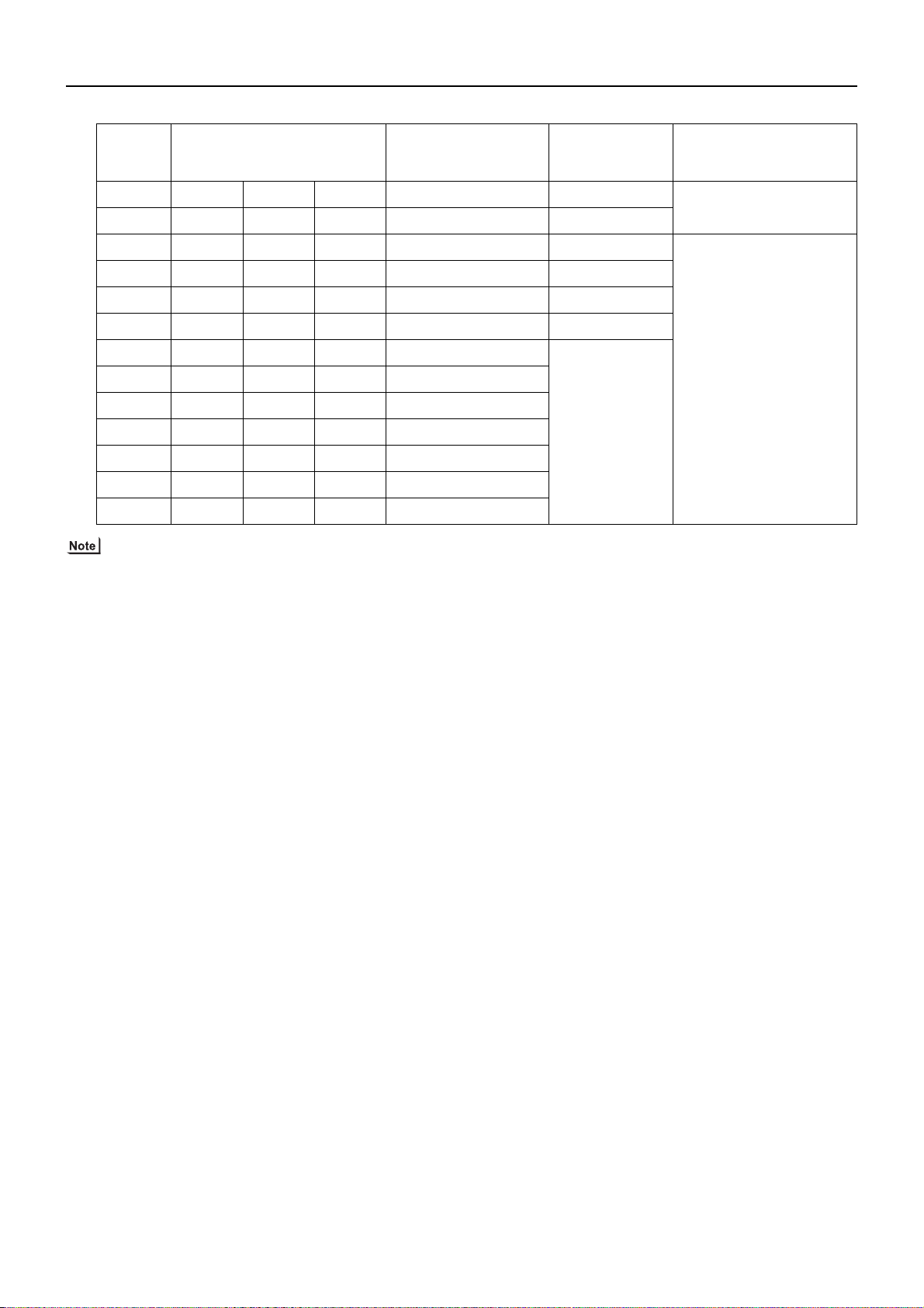
1) "Maximum total capacity of connectable indoor units" refers to the sum of the numeric values in the indoor unit model names.
2) If the total capacity of the indoor units that are connected to a given outdoor unit exceeds the capacity of the outdoor unit, the
indoor units will not be able to perform at the rated capacity when they are operated simultaneously. Select a combination of
units so that the total capacity of the connected indoor units is at or below the capacity of the outdoor unit whenever possible.
HWE07010 GB
- 17 -
[ II Restrictions ]
(2) High COP combinations
Outdoor
units
Composing units Maximum total capacity
of connectable indoor
units
Maximum number
of connectable in-
door units
Types of connectable in-
door units
200 - - - 100 - 260 17 P15 - P200 models
300 - - - 150 - 390 26
R410A series indoor units
400 200 200 - 200 - 520 34 P15 - P500 models
450 250 200 - 225 - 585 39
R410A series indoor units
500 300 200 - 250 - 650 43
550 300 250 - 275 - 715 47
600 300 300 - 300 - 780 50
650 350 300 - 325 - 845
700 300 200 200 350 - 910
750 300 250 200 375 - 975
800 300 300 200 400 - 1040
850 300 300 250 425 - 1105
900 300 300 300 450 - 1170
1) "Maximum total capacity of connectable indoor units" refers to the sum of the numeric values in the indoor unit model names.
2) If the total capacity of the indoor units that are connected to a given outdoor unit exceeds the capacity of the outdoor unit, the
indoor units will not be able to perform at the rated capacity when they are operated simultaneously. Select a combination of
units so that the total capacity of the connected indoor units is at or below the capacity of the outdoor unit whenever possible.
HWE07010 GB
- 18 -
[ II Restrictions ]
[2] Types and Maximum allowable Length of Cables
1. Wiring work
(1) Notes
1) Have all electrical work performed by an authorized electrician according to the local regulations and instructions in this manual.
2) Instal l external transmission cables at least 5cm [1-31/32"] away from the power supply cable to avoid noise interference.
(Donot put the control cable and power supply cable in the same conduit tube.)
3) Provide grounding for the outdoor unit as required.
4) Run the cable from the electric box of the indoor or outdoor unit in such way that the box is accessible for servicing.
5) Do not connect power supply wiring to the terminal block for transmission line. Doing so will damage the electronic components on the terminal block.
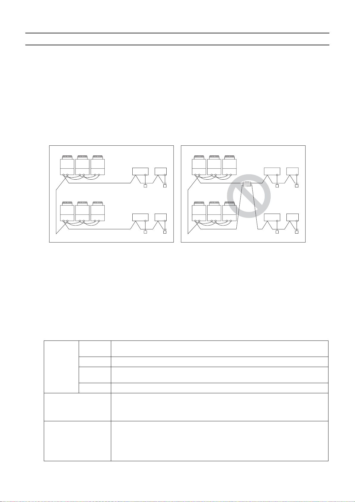
6) Use 2-core shielded cables as transmission cables.
Use a separate 2-core control cable for each refrigerant system. Do not use a single multiple-core cable to connect indoor
units that belong to different refrigerant systems. The use of a multiple-core cable may result in signal transmission errors and
malfunctions.
TB
TB
3
TB
TB
3
Outdoor unit
7
7
TB3TB7TB3TB
2-core shielded cable
TB3TB
TB3TB
7
2-core shielded cable
Indoor unit
7
Remote Controller
7
TB3: Terminal block for indoor-outdoor transmission line TB7: Terminal block for centralized control
TB
TB
3
TB
TB
3
Outdoor unit
7
7
TB3TB7TB3TB
TB3TB
TB3TB
7
Indoor unit
7
multiple-core cable
Remote Controller
7
(2) Control wiring
Different types of control wiring are used for different systems.
Refer to section "[5] An Example of a System to which an MA Remote Controller is connected - [7] An Example of a System
to which both MA Remote Controller and M-NET Remote Controller are connected" before performing wiring work.
Types and maximum allowable length of cables
Control lines are categorized into 2 types: transmission line and remote controller line.
Use the appropriate type of cables and observe the maximum allowable length specified for a given system. If a given system
has a long transmission line or if a noise source is located near the unit, place the unit away from the noise source to reduce
noise interference.
1) M-NET transmission line
Facility
type
All facility types
Type Shielded cable CVVS, CPEVS, MVVS
Cable type
Number of
cores
Cable size Larger than 1.25mm
2-core cable
2
[AWG16]
Maximum transmission
line distance between the
outdoor unit and the far-
200 m [656ft] max.
thest indoor unit
Maximum transmission
line distance for centralized control and Indoor/
outdoor transmission line
(Maximum line distance
500 m [1640ft] max.
*The maximum overall line length from the power supply unit on the transmission lines for
centralized control to each outdoor unit or to the system controller is 200m [656ft] max.
via outdoor unit)
HWE07010 GB
- 19 -
[ II Restrictions ]
2) Remote controller wiring
MA remote controller
Type CVV CVV
Number of
cores
Cable type
Cable size
2-core cable 2-core cable
0.3 to 1.25mm
[AWG22 to 16]
(0.75 to 1.25mm2 )
[AWG18 to 16]
Maximum overall line
length
200 m [656ft] max.
*1 MA remote controller refers to MA remote controller (PAR-20MAA, PAR-21MAA), MA simple remote controller, and
wireless remote controller.
*2 M-NET remote controller refers to ME remote controller and ME simple remote controller.
*3 The use of cables that are smaller than 0.75mm
*4 When connected to the terminal block on the Simple remote controller, use cables that meet the cable size specifi-
cations shown in the parenthesis.
[3] Switch Settings and Address Settings
2 *3
*4
*1
0.3 to 1.25mm
[AWG22 to 16]
(0.75 to 1.25mm2 )
M-NET remote controller
[AWG18 to 16]
The section of the cable that exceeds 10m
[32ft] must be included in the maximum indoor-outdoor transmission line distance.
2
(AWG18) is recommended for easy handling.
2 *3
*4
*2
1. Switch setting
Refer to section "[5] An Example of a System to which an MA Remote Controller is connected - [7] An Example of a System
to which both MA Remote Controller and M-NET Remote Controller are connected" before performing wiring work.
Set the switches while the power is turned off.
If the switch settings are changed while the unit is being powered, those changes will not take effect, and the unit will not
function properly.
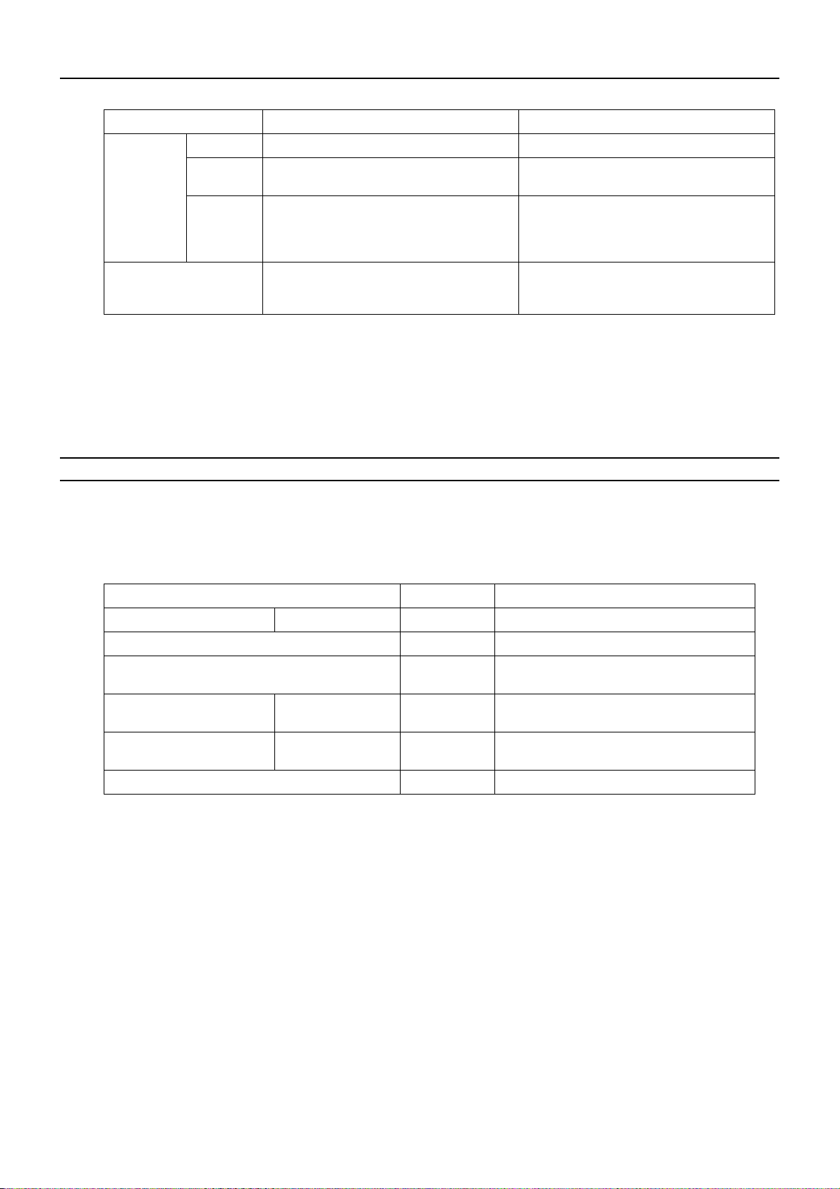
Units on which to set the switches Symbol Units to which the power must be shut off
*3
CITY MULTI indoor unit Main/sub unit IC Outdoor units
LOSSNAY, OA processing unit
*1
LC Outdoo r units
Air handling kit IC Outdoor units
and Indoor units
*3
and LOSSNAY
*3
or field supplied air handling
unit
M-NET remote controller Main/sub remote
RC Outdoor units
*3
controller
MA remote controller Main/sub remote
MA Indoor units
controller
CITY MULTI outdoor unit
*2
OC,OS1,OS2 Outdoor units
*3
*1. Applicable when LOSSNAY units are connected to the indoor-outdoor transmission line.
*2. The outdoor units in the same refrigerant circuit are automatically designated as OC, OS1, and OS2 in the order of
capacity from large to small (if two or more units have the same capacity, in the order of address from small to large).
*3. Turn off the power to all the outdoor units in the same refrigerant circuit.
HWE07010 GB
- 20 -
[ II Restrictions ]
2. M-NET Address settings
(1) Address settings table
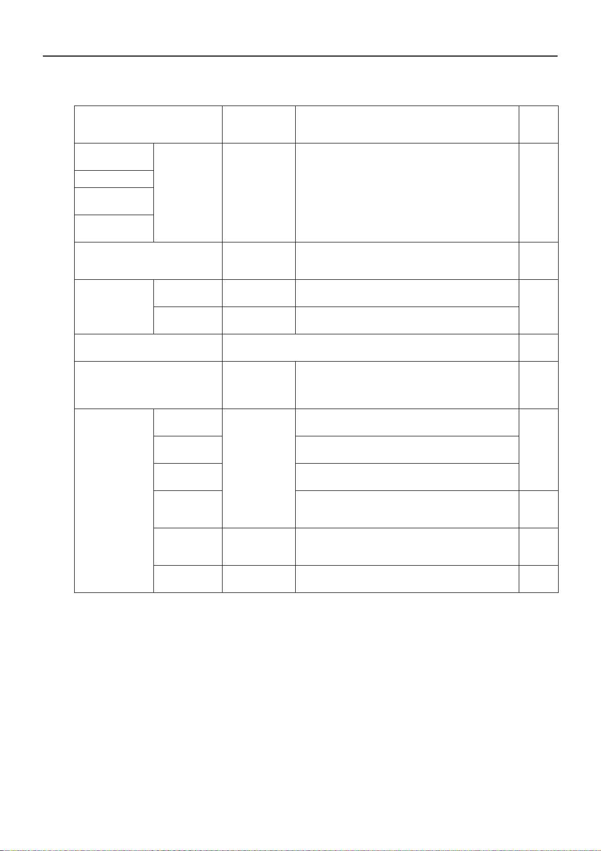
The need for address settings and the range of address setting depend on the configuration of the system.
Unit or controller Address setting
Setting method Facto-
range
CITY MULTI indoor unit
Main/sub unit 00,
01 to 50
*1
Assign the smallest address to the main indoor u nit in the
group, and assign sequential address numbers to the rest
of the indoor units in the same group.
*4
M-NET adapter
M-NET control in-
terface
Free Plan adapt-
er
LOSSNAY, OA processing unit
Air handling kit
00,
01 to 50
*1
Assign an arbitrary but unique address to each of
these units after assigning an address to all indoor
units.
M-NET remote
controller
Main remote
controller
Sub remote
controller
101 to 150 Add 100 to the smallest address of all the indoor units
in the same group.
151 to 200
*2
Add 150 to the smallest address of all the indoor units
in the same group.
MA remote controller No address settings required. (The main/sub setting must be made if 2
remote controllers are connected to the system.)
CITY MULTI outdoor unit 00,
51 to 100
*1,*3
Assign sequential addresses to the outdoor units in the
same refrigerant circuit. The outdoor units in the same
refrigerant circuit are automatically designated as OC
and OS.
*5
ry set-
ting
00
00
101
Main
00
System controller Group remote
controller
System remote
controller
ON/OFF re-
mote controller
Schedule timer
(compatible
201 to 250 Assign an address that equals the sum of the smallest
group number of the group to be controlled and 200.
Assign an arbitrary but unique address within the
range listed on the left to each unit.
Assign an address that equals the sum of the smallest
group number of the group to be controlled and 200.
Assign an arbitrary but unique address within the
range listed on the left to each unit.
201
202
with M-NET)
Central con-
troller
G(B)-50A
000,
201 to 250
Assign an arbitrary but unique address within the
range listed on the left to each unit. The address must
be set to "000" to control the K-control unit.
LM adapter 201 to 250 Assign an arbitrary but unique address within the
000
247
range listed on the left to each unit.
*1. Address setting is not required for a City Multi system that consists of a single refrigerant circuit (with some exceptions).
*2. To set the M-NET remote controller address to "200", set it to "00".
*3. To set the outdoor unit address to "100," set the switches to "50."
*4. Some indoor units have 2 or 3 controller boards that require address settings.
No. 2 controller board address must be equal to the sum of the No. 1 controller board address and 1, and the No.3
controller board address must equal to the No. 1 controller address and 2.
*5. The outdoor units in the same refrigerant circuit are automatically designated as OC, OS1, and OS2 in the order of
capacity from large to small (if two or more units have the same capacity, in the order of address from small to large).
HWE07010 GB
- 21 -
 Loading...