


|
|
|
|
2000 |
|
|
|
|
|
|
|
|||
AIR-COOLED HEAT PUMP TYPE |
||||
PACKAGED AIR CONDITIONERS |
|
|||
TECHNICAL & SERVICE MANUAL
<Outdoor unit>
Models
PUH-8YE, PUH-10YE
(Single and Twin/Triple)
For use with the R22
Contents
|
|
|
Page |
1 |
SAFETY PRECAUTIONS ........................................................................................................... |
1 |
|
2 |
SPECIFICATIONS ...................................................................................................................... |
3 |
|
3 |
EXTERNAL DIMENSIONS ......................................................................................................... |
5 |
|
4 |
ELECTRICAL WIRING DIAGRAM ............................................................................................. |
6 |
|
|
[1] |
Outdoor Unit ........................................................................................................................ |
6 |
|
[2] Skelton of Indoor/Outdoor Connection ................................................................................ |
7 |
|
5 |
Technical Data of PUH-8YE/10YE to Meet LVD ....................................................................... |
8 |
|
|
[1] |
Standard Operation Data ..................................................................................................... |
8 |
|
[2] |
Cooling Capacity Curves ..................................................................................................... |
9 |
|
[3] |
Heating Capacity Curves ..................................................................................................... |
9 |
|
[4] Capacity Reduction Ratio due to Changes in Piping Length ............................................. |
10 |
|
|
[5] Center of Gravity (Outdoor unit) ........................................................................................ |
11 |
|
|
[6] |
NC Curve (Outdoor unit) ................................................................................................... |
12 |
6 |
SERVICE DATA ........................................................................................................................ |
13 |
|
|
[1] |
Appearance of Equipment ................................................................................................. |
13 |
|
[2] |
Refrigerant Circuit .............................................................................................................. |
15 |
|
[3] Limitation of Refrigerant Piping Length.............................................................................. |
15 |
|
|
[4] |
Refrigerant Piping .............................................................................................................. |
16 |
|
[5] |
Refrigerant Charge ............................................................................................................ |
16 |
|
[6] |
Operation Rage ................................................................................................................. |
16 |
7 |
CONTROL ................................................................................................................................ |
17 |
|
|
[1] |
Composition of Control ...................................................................................................... |
17 |
|
[2] |
Control specifications ......................................................................................................... |
17 |
|
[3] Function of switches and connectors (outdoor unit) .......................................................... |
21 |
|
|
[4] Simple parts check method ............................................................................................... |
25 |
|
|
[5] |
Reference Data .................................................................................................................. |
26 |
|
[6] |
Self-diagnosis and troubleshooting .................................................................................... |
27 |
|
[7] |
TEST RUN ......................................................................................................................... |
32 |
1 SAFETY PRECAUTIONS
1. Before installation and electric work
sBefore installing the unit, make sure you read all the “Safety precautions”.
sThe “Safety precautions” provide very important points regarding safety. Make sure you follow them.
Symbols used in the text
 Warning:
Describes precautions that should be observed to prevent danger of injury or death to the user.  Caution:
Describes precautions that should be observed to prevent damage to the unit.
Symbols used in the illustrations
: Indicates an action that must be avoided.
: Indicates that important instructions must be followed. : Indicates a part which must be grounded.
: Beware of electric shock. (This symbol is displayed on the main unit label.) <Color: yellow>
 Warning:
Carefully read the labels affixed to the main unit.
 Warning:
•Use the specified cables for wiring. Make the connections securely so that the outside force of the cable is not applied to the terminals.
-Inadequate connection and fastening may generate heat and cause a fire.
•Do not touch the heat exchanger fins.
-Improper handling may result in injury.
•If refrigerant gas leaks during installation work, ventilate the room.
-If the refrigerant gas comes into contact with a flame, poisonous gases will be released.
•Have all electric work done by a licensed electrician according to “Electric Facility Engineering Standard” and “Interior Wire Regulations”and the instructions given in this manual and always use a special circuit.
-If the power source capacity is inadequate or electric work is performed improperly, electric shock and fire may result.
•Securely install the outdoor unit terminal cover (panel).
-If the terminal cover (panel) is not installed properly, dust or water may enter the outdoor unit and fire or electric shock may result.
•When installing and moving the air conditioner to another site, do not charge the it with a refrigerant different from the refrigerant (R407C or R22) specified on the unit.
-If a different refrigerant or air is mixed with the original refrigerant, the refrigerant cycle may malfunction and the unit may be damaged.
•When moving and reinstalling the air conditioner, consult the dealer or an authorized technician.
-If the air conditioner is installed improperly, water leakage, electric shock, or fire may result.
•Do not reconstruct or change the settings of the protection devices.
-If the pressure switch, thermal switch, or other protection device is shorted and operated forcibly, or parts other than those specified by Mitsubishi Electric are used, fire or explosion may result.
2. Precautions for devices that use R407C refrigerant
 Caution:
•Do not use the existing refrigerant piping.
-The old refrigerant and refrigerator oil in the existing piping contains a large amount of chlorine which may cause the refrigerator oil of the new unit to deteriorate.
•Use refrigerant piping made of phosphorus deoxidized copper and copper alloy seamless pipes and tubes. In addition, be sure that the inner and outer surfaces of the pipes are clean and free of hazardous sulphur, oxides, dust/dirt, shaving particles, oils, moisture, or any other contaminant.
-Contaminants on the inside of the refrigerant piping may cause the refrigerant residual oil to deteriorate.
•Store the piping to be used during installation indoors and keep both ends of the piping sealed until just before brazing. (Store elbows and other joints in a plastic bag.)
-If dust, dirt, or water enters the refrigerant cycle, deterioration of the oil and compressor trouble may result.
–1–
•Use ester oil, ether oil or alkylbenzene (small amount) as the refrigerator oil to coat flares and flange connections.
-The refrigerator oil will degrade if it is mixed with a large amount of mineral oil.
•Use liquid refrigerant to fill the system.
-If gas refrigerant is used to seal the system, the composition of the refrigerant in the cylinder will change and performance may drop.
•Do not use a refrigerant other than R407C.
-If another refrigerant (R22, etc.) is used, the chlorine in the refrigerant may cause the refrigerator oil to deteriorate.
•Use a vacuum pump with a reverse flow check valve.
-The vacuum pump oil may flow back into the refrigerant cycle and cause the refrigerator oil to deteriorate.
•Do not use the following tools that are used with conventional refrigerants.
(Gauge manifold, charge hose, gas leak detector, reverse flow check valve, refrigerant charge base, refrigerant recovery equipment)
-If the conventional refrigerant and refrigerator oil are mixed in the R407C, the refrigerant may deteriorated.
-If water is mixed in the R407C, the refrigerator oil may deteriorate.
-Since R407C does not contain any chlorine, gas leak detectors for conventional refrigerants will not react to it.
•Do not use a charging cylinder.
-Using a charging cylinder may cause the refrigerant to deteriorate.
•Be especially careful when managing the tools.
-If dust, dirt, or water gets in the refrigerant cycle, the refrigerant may deteriorate.
3. Electrical work
 Caution:
•Ground the unit.
-Do not connect the ground wire to gas or water pipes, lightning rods, or telephone ground lines. Improper grounding may result in electric shock.
•The reverse phase of L lines (L1, L2, L3) can be detected (Error cord: F8), but the reverse phase of L lines and N line can be not be detected.
-The some electric parts should be damaged when power is supplied under the miss wiring.
•Use power line cables of sufficient current carrying capacity and rating.
-Cables that are too small may leak, generate heat, and cause a fire.
•Use only a circuit breaker and fuse of the specified capacity.
-A fuse or circuit breaker of a larger capacity or a steel or copper wire may result in a general unit failure or fire.
•Do not wash the air conditioner units.
-Washing them may cause an electric shock.
4. Before starting the test run
 Caution:
•Turn on the power at least 12 hours before starting operation.
-Starting operation immediately after turning on the main power switch can result in severe damage to internal parts. Keep the power switch turned on during the operational season.
•Do not touch the switches with wet fingers.
-Touching a switch with wet fingers can cause electric shock.
•Do not touch the refrigerant pipes during and immediately after operation.
-During and immediately after operation, the refrigerant pipes are may be hot and may be cold, depending on the condition of the refrigerant flowing through the refrigerant piping, compressor, and other refrigerant cycle parts. Your hands may suffer burns or frostbite if you touch the refrigerant pipes.
•Do not operate the air conditioner with the panels and guards removed.
-Rotating, hot, or high-voltage parts can cause injuries.
•Do not turn off the power immediately after stopping operation.
-Always wait at least five minutes before turning off the power. Otherwise, water leakage and trouble may occur.
Note:
1.The total capacity of connected indoor unit models represents the total sum of the figures expressed in the indoor model name.
2.Combinations in which the total capacity of the connected indoor units exceeds the capacity of the outdoor unit will reduce the capacity of each indoor unit below the rated capacity during simultaneous operation. Therefore, if circumstances allows, combine indoor units within the capacity of the outdoor unit.
–2–

2 SPECIFICATIONS
Specifications of air-source heat pump type packaged air conditioner (Outdoor unit)
Model name |
|
|
|
|
PUH-8YE |
|
|
Quantity |
|
|
|
|
|
|
|
|
|
|
|
|
|
|
|
|
|
|
|
|
|
|
|
|
|
|
|
|
|
|
|
|
|
|
|
Cooling |
|
Heating |
|
|
|
|
|
|
|
|
|
|
|
|
|
Capacity |
|
|
|
|
kcal/h |
18,000 |
|
|
19,000 |
||
|
|
|
|
|
|
|
|
|
|
||
|
|
|
|
kW |
20.9 |
|
|
22.1 |
|||
|
|
|
|
|
|
|
|
||||
|
|
|
|
|
|
|
|
|
|
|
|
Power source |
|
|
|
|
|
|
3N~ 380/400/415 V 50 Hz |
||||
|
|
|
|
|
|
|
|
|
|
|
|
Power input |
|
|
|
|
kW |
7.62 |
|
|
7.17 |
||
|
|
|
|
|
|
|
|
|
|
|
|
Current |
|
|
|
|
A |
13.5/13.6/13.7 |
|
12.3/12.4/12.5 |
|||
|
|
|
|
|
|
|
|
|
|
||
|
|
|
Type x Quantity |
|
|
|
Propeller fan × 1 |
||||
|
|
|
|
|
|
|
|
|
|
|
|
Fan |
|
Airflow rate |
|
m3/min |
|
|
|
185 |
|||
|
|
|
|
|
|
|
|
|
|
|
|
|
|
|
Motor output |
|
kW |
|
|
|
0.38 |
||
|
|
|
|
|
|
|
|
|
|
|
|
|
|
|
Type |
|
|
|
|
|
|
Hermetic |
|
|
|
|
|
|
|
|
|
|
|
|
|
Compressor |
|
Motor output |
|
kW |
|
|
|
5.5 |
|||
|
|
|
|
|
|
|
|
|
|
|
|
|
|
|
Crankcase heater |
|
kW |
|
|
|
0.05 (240 V) |
||
|
|
|
|
|
|
|
|
|
|
||
Refrigerant/Lubricant |
|
|
|
|
|
R22/MS32(N-1) |
|||||
|
|
|
|
|
|
|
|
|
|
|
|
External finish |
|
|
|
|
|
Steel plate paintingwith polyester powder |
|||||
|
|
|
|
|
|
|
|
(MUNSELL 5Y8/1 or similar) |
|||
|
|
|
|
|
|
|
|
|
|
||
External dimension |
|
|
mm |
|
1,715(H) × 990(W) × 840(L) |
||||||
|
|
|
|
|
|
|
|
|
|
||
Protection |
|
High pressure protection |
MPa |
|
|
|
2.94 |
||||
device |
|
|
|
|
|
|
|
|
|||
|
Compressor/Fan |
|
|
Overcurrent protection/Thermal switch |
|||||||
|
|
|
|
|
|
|
|
|
|||
Refrigerant piping diameter |
Liquid/Gas |
mm |
|
ø12.7 Flare / ø25.4 Flange |
|||||||
|
|
|
|
|
|
|
|
|
|
|
|
Indoor unit |
|
|
|
|
|
|
|
|
PEH-8YD |
||
|
|
|
|
|
|
|
|
|
|
|
|
Noise level |
|
|
|
|
dB (A) |
|
|
|
56 |
||
|
|
|
|
|
|
|
|
|
|
|
|
Net weight |
|
|
|
|
kg |
|
|
|
205 |
||
|
|
|
|
|
|
|
|
|
|
|
|
Operating temperature range |
|
|
Indoor: 15 °CWB~24 °CWB |
Indoor: 15°CDB~27 °CDB |
|||||||
|
|
Outdoor: –5 °CDB~46 °CDB |
Outdoor: –12 °CWB~15.5 °CWB |
||||||||
|
|
|
|
|
|
|
|||||
|
|
|
|
|
|
|
|
||||
1. Cooling/Heating capacity indicates the maximum value at operation under the following condition. |
|||||||||||
|
|
Cooling |
Indoor: |
27 °CDB/19 °CWB |
Outdoor: |
35 °CDB |
|||||
Notes: |
Heating |
Indoor: |
20 °CDB |
|
Outdoor: |
7 °CDB/6 °CWB |
|||||
|
|
Pipe length: 7.5 m |
|
Height difference: 0 m |
|||||||
|
|
|
|
|
|||||||
2. Works not included: Installation/Foundation work, Electrical connection work, Duct work, Insulation work, Power source switch, and other items not specified in this specifications.
–3–

Specifications of air-source heat pump type packaged air conditioner (Outdoor unit)
Model name |
|
|
|
|
PUH-10YE |
|
|
Quantity |
|
|
|
|
|
|
|
|
|
|
|
|
|
|
|
|
|
|
|
|
|
|
|
|
|
|
|
|
|
|
|
|
|
|
|
Cooling |
|
Heating |
|
|
|
|
|
|
|
|
|
|
|
|
|
Capacity |
|
|
|
|
kcal/h |
22,400 |
|
|
24,400 |
||
|
|
|
|
|
|
|
|
|
|
||
|
|
|
|
kW |
26.0 |
|
|
28.4 |
|||
|
|
|
|
|
|
|
|
||||
|
|
|
|
|
|
|
|
|
|
|
|
Power source |
|
|
|
|
|
|
3N~ 380/400/415 V 50 Hz |
||||
|
|
|
|
|
|
|
|
|
|
|
|
Power input |
|
|
|
|
kW |
9.47 |
|
|
8.30 |
||
|
|
|
|
|
|
|
|
|
|
|
|
Current |
|
|
|
|
A |
16.8/16.9/17.0 |
|
14.8/14.9/15.0 |
|||
|
|
|
|
|
|
|
|
|
|
||
|
|
|
Type x Quantity |
|
|
|
Propeller fan × 1 |
||||
|
|
|
|
|
|
|
|
|
|
|
|
Fan |
|
Airflow rate |
|
m3/min |
|
|
|
185 |
|||
|
|
|
|
|
|
|
|
|
|
|
|
|
|
|
Motor output |
|
kW |
|
|
|
0.38 |
||
|
|
|
|
|
|
|
|
|
|
|
|
|
|
|
Type |
|
|
|
|
|
|
Hermetic |
|
|
|
|
|
|
|
|
|
|
|
|
|
Compressor |
|
Motor output |
|
kW |
|
|
|
7.5 |
|||
|
|
|
|
|
|
|
|
|
|
|
|
|
|
|
Crankcase heater |
|
kW |
|
|
|
0.06 (240 V) |
||
|
|
|
|
|
|
|
|
|
|
||
Refrigerant/Lubricant |
|
|
|
|
R22/MS-32(N-1) |
||||||
|
|
|
|
|
|
|
|
|
|
|
|
External finish |
|
|
|
|
|
Steel plate painting with polyester powder |
|||||
|
|
|
|
|
|
|
|
(MUNSELL 5Y8/1 or similar) |
|||
|
|
|
|
|
|
|
|
|
|
||
External dimension |
|
|
mm |
|
1,715(H) × 990(W) × 840(L) |
||||||
|
|
|
|
|
|
|
|
|
|
||
Protection |
|
High pressure protection |
MPa |
|
|
|
2.94 |
||||
|
|
|
|
|
|
|
|
|
|
||
device |
|
Compressor/Fan |
|
|
Overcurrent protection/Thermal switch |
||||||
|
|
|
|
|
|
|
|
|
|||
Refrigerant piping diameter |
Liquid/Gas |
mm |
|
ø15.88 Flare / ø28.58 Flange |
|||||||
|
|
|
|
|
|
|
|
|
|
|
|
Indoor unit |
|
|
|
|
|
|
|
|
PEH-10YD |
||
|
|
|
|
|
|
|
|
|
|
|
|
Noise level |
|
|
|
|
dB (A) |
|
|
|
57 |
||
|
|
|
|
|
|
|
|
|
|
|
|
Net weight |
|
|
|
|
kg |
|
|
|
225 |
||
|
|
|
|
|
|
|
|
|
|
|
|
Operating temperature range |
|
|
Indoor: 15 °CWB~24 °CWB |
Indoor: 15 °CDB~27 °CDB |
|||||||
|
|
Outdoor: –5 °CDB~46 °CDB |
Outdoor: –12 °CWB~15.5 °CWB |
||||||||
|
|
|
|
|
|
|
|||||
|
|
|
|
|
|
|
|
||||
1. Cooling/Heating capacity indicates the maximum value at operation under the following condition. |
|||||||||||
|
|
Cooling |
Indoor: |
27 °CDB/19 °CWB |
Outdoor: |
35 °CDB |
|||||
Notes: |
Heating |
Indoor: |
20 °CDB |
|
Outdoor: |
7 °CDB/6 °CWB |
|||||
|
|
Pipe length: 7.5 m |
|
Height difference: 0 m |
|
||||||
|
|
|
|
|
|
||||||
2. Works not included: Installation/Foundation work, Electrical connection work, Duct work, Insulation work, Power source switch,and other items not specified in this specifications.
–4–
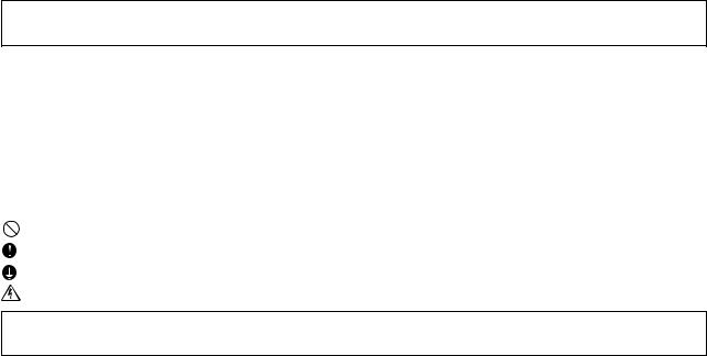
–5–
12 |
5 |
|
|
|
Y |
|
|
|
|
|
|
|
|
Note1 |
|
|
Y |
|
|
|
|
|
|
|
|
Knockout hole |
|
||
|
50 |
Bottom piping hole |
|
||
|
|
|
|
|
|
|
|
237 |
198 |
73 80 |
|
|
|
Conn. pipe |
|
25 |
160 |
|
|
8 : ø 25.4<brazed> |
|
|
|
Crosss section Y-Y |
10 : ø 28.58<brazed> |
|
Cross section X-X |
||
|
|
|
|||
4 2 - 14 20 Oval hole
215 |
560 |
215 |
|
990 |
|
Plane view
234
100 251
Knockout hole
Rear view
ø 27 Knockout hole <Left side hole for the control wiring>
Knockout hole Left piping hole
|
|
Knockout hole |
||
|
|
MOOEL |
A |
|
|
|
PUH-8YE |
12.7 |
|
|
|
PUH-10YE |
15.88 |
|
|
|
Refrig. service |
||
|
|
valve (liquid) |
||
60 |
75 |
øA<flare> |
|
|
|
ø 40 Knockout hole |
|
X |
|
|
<Left side hole for |
|
||
|
|
|
||
|
the power supply> |
|
|
|
|
|
|
|
40 |
|
100 |
194 |
149 |
70 |
|
|
48 |
79 |
83 |
Knockout hole |
|
|
Refrig. service |
|||
80 |
40 |
Front piping hole |
|||
|
|
valve (gas) |
|
|
|
|
|
<flange> |
31 |
165 |
|
Left side view |
Front view |
15 |
< Accessory > |
|
|
||
|
• |
Refrigerant (gas) conn. pipe ···········1 pc. |
|
|
(The connecting pipe is fixed with the unit) |
|
• |
Packing for conn. pipe ·················1 pc. |
|
|
(Attached near the ball valve) |
|
• |
Conduit mouting plate |
840 880 |
910 |
(Painted the same color as the unit body) |
|
|
ø40,ø33,ø27 ·························each 1pc. |
|
• |
Tapping screw 4 10 ················4 pcs. |
|
Note |
Please leave a space under the outdoor unit |
|
|
for the piping When you connect the piping |
|
|
from the bottom. , |
15 |
|
(Please be careful not to close the hole |
|
of the bottom plate by the basement) |
|
|
|
|
|
|
Air outlet |
|
225 |
|
|
Air |
|
inlet |
1715 |
Air |
1490 |
inlet |
Service panel
X
Right side view
• |
3 |
8YE/10YE-PUH Models |
DIMENSIONS EXTERNAL |
mm Unit:
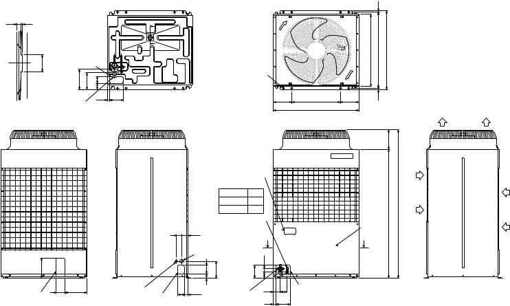
4ELECTRICAL WIRING DIAGRAM
[1]Outdoor Unit
• Models PUH-8YE/10YE
|
|
|
|
|
MF |
|
|
MC |
|
|
1 |
|
3 |
|
|
Red White Black |
(3P) |
|
|
|
(1P) |
||
|
|
1 |
|
4 |
|
|
|
51C |
|
|
|
|
|
(4P) |
|
|
|
|
|
|
|
|
|
|
|
|
1 |
3 |
5 |
|
|
|
|
|
CNFAN |
|
1 |
||
|
|
|
(5P) |
CNFC2 |
|
||
52C |
F.C. |
|
|
|
|||
|
(6P) |
|
|
||||
|
|
|
|
||||
|
BOARD |
|
6 |
||||
|
|
|
CNPOW |
|
|||
|
|
|
|
|
|||
|
|
|
|
(5P) |
|
|
|
|
CNOUT1 |
1 |
3 |
5 |
1 |
3 |
|
|
(5P) |
|
|||||
|
1 |
|
|
|
|
|
CNOUT2 |
|
3 |
|
F10 |
|
|
(3P) |
|
|
|
|
|
|
|||
|
|
|
|
|
|
|
|
|
5 |
|
|
F20 |
|
|
|
|
|
|
|
|
|
|
|
|
7 |
|
|
|
F30 |
|
|
|
CNIN |
|
N.F.BOARD |
||||
|
|
(7P) |
|
||||
Red White |
Black |
Blue |
Green/Yellow |
|
TB1 |
L1 L2 L3 N |
TB3 |
|
|
|
|
|
|
|
TH1 |
TH2 |
|
|
|
|
|
|
2 1 |
2 1 |
|
|
|
CNVMNT |
CNMNT |
CN40 |
CN2 |
CN3 |
CN4 |
1 |
CN23 (3P) |
(3P) |
(5P) |
(6P) |
(2P) |
(2P) |
(2P) |
49C |
3 |
|
|
|
|
|
|
|
|
CN3D |
|
|
|
|
|
|
|
|
|
|
|
||
|
|
|
|
|
|
|
|
|
|
|
|
|
1 |
CN22 (3P) |
|
|
|
|
|
|
|
(3P) |
|
51C |
3 |
|
ON |
|
|
|
|
|
|
CN3S |
|
|
|
|
|
|
|
|
|
|
|||
|
|
|
|
|
|
|
|
|
|
||
|
1 |
CN21 (3P) |
OFF |
1 |
4 |
|
|
|
|
(3P) |
|
63H1 |
|
|
|
|
|
|
|
|
|
||
3 |
|
|
SW5 |
|
|
|
|
CN3N |
|
||
|
|
|
|
|
ON |
ON |
|
|
|
|
|
52C |
|
|
X04 |
|
|
|
|
(3P) |
|
||
1 |
CN26 (5P) |
|
|
|
|
|
|
63H2 |
|||
|
OFF |
1 2 OFF |
1 |
|
6 |
|
|||||
|
3 |
|
|
|
SW1 |
CN24 |
|||||
52C |
|
X03 |
|
SW3 |
SW4 |
|
|
3 |
|||
5 |
|
|
|
|
|
|
|
(3P) |
1 |
||
|
|
|
|
|
|
|
|
|
|
|
|
|
1 |
CN25 (3P) |
LED1 |
ON |
|
|
|
CN27 |
|
||
CH |
3 |
|
OFF |
|
|
|
|
||||
|
1 |
|
6 |
(3P) |
|
||||||
|
|
|
|
|
SW2 |
|
|||||
|
|
CN53 (3P) |
X01 |
|
|
|
|||||
|
1 |
|
|
|
|
|
|
|
|
||
21S4 |
3 |
|
|
|
|
|
|
|
|
CN81 |
3 |
|
|
|
|
|
|
|
|
|
|
||
|
1 |
CN52 (6P) |
X02 |
|
|
|
|
|
|
(3P) |
1 |
SV1 |
|
|
X05 |
|
|
|
|
|
|
|
|
|
|
|
|
|
|
|
|
|
|
||
|
5 |
|
|
|
|
|
|
|
|
CN51 |
|
|
|
|
|
|
|
|
|
|
|
|
|
|
1 |
CNFC1 (6P) |
|
|
|
|
|
|
|
(5P) |
|
|
|
|
|
|
|
|
|
|
|
||
|
6 |
|
|
|
|
|
|
|
|
|
|
L1 |
7 |
CN20(7P) |
|
|
|
|
|
|
|
|
|
|
|
|
|
|
|
|
|
|
|
||
N |
|
F01 |
|
|
|
|
DC power supply |
|
|||
|
F04 |
|
|
|
|
|
|||||
L2 |
|
|
|
|
|
|
|
|
|
|
|
|
|
|
|
|
|
|
|
|
|
|
|
L3 |
1 |
F02 |
|
|
|
|
|
|
|
|
|
|
|
|
|
|
|
|
|
|
|
||
|
|
F03 |
|
|
|
|
|
|
|
|
|
|
|
|
CNFG |
|
|
CN28 |
|
CN34 |
|
|
|
|
|
|
(3P) |
|
|
(3P) |
|
(3P) |
|
|
|
Unit body |
|
3 |
1 |
|
|
3 |
1 |
3 |
|
1 |
|
|
|
|
|
|
|
|
|
|
|
|
|
TR
|
|
1 2 3 |
Controller Box |
L1 L2 L3 |
N |
To indoor unit |
|
|
|
|
Power source 3N~ 380/400/415 V 50 Hz
NOTE SW5-4 IS OFF IN CASE OF PUH-8YE.
SW5-4 IS ON IN CASE OF PUH-10YE.
ON |
|
|
|
|
|
|
|
ON |
|
|
|
|
|
|
OFF |
|
|
|
|
|
|
|
OFF |
|
|
|
|
|
|
1 4 |
1 4 |
|||||||||||||
|
SW5 |
|
SW5 |
|||||||||||
PUH-8YE PUH-10YE
Note:
1.Be sure to apply earth work to the unit. (Use the earth terminal of TB1.)
Symbol Explanation
Symbol |
|
Name |
|
F01~F04 |
FUSE (6.3A 250VAC CLASS F) |
||
|
|
|
|
F10~F30 |
FUSE (6.3A 250VAC CLASS F) |
||
|
|
|
|
51C |
OVER CURRENT RELAY |
||
|
|
|
|
52C |
MAGNETIC CONTACTOR (COMPRESSOR) |
||
|
|
|
|
63H1 |
PRESSURE SWITCH (HIGH PRESSURE) |
||
|
|
|
|
63H2 |
PRESSURE SWITCH (FOR CONTROL) |
||
|
|
|
|
TR |
TRANSFORMER |
||
|
|
|
|
MC |
ELECTRIC MOTOR OF COMPRESSOR |
||
|
|
|
|
MF |
FAN MOTOR (HEAT EXCHANGER) |
||
|
|
|
|
CH |
CRANK CASE HEATER (COMPRESSOR) |
||
|
|
|
|
X01~X05 |
RELAY |
||
|
|
|
|
SW1~5 |
SWITCH |
||
|
|
|
|
21S4 |
4-WAY VALVE |
||
|
|
|
|
SV1 |
SORENOID VALVE |
||
|
|
|
|
TH1 |
THERMISTOR |
LIQUID TEMP |
|
|
|
||
TH2 |
DISCHARGE TEMP |
||
|
|||
|
|
|
|
TB1 |
POWER SOURCE TERMINAL BLOCK |
||
|
|
|
|
TB3 |
INDOOR/OUTDOOR CONNECTION TERMINAL |
||
BLOCK |
|||
|
|||
|
|
|
|
49C |
THERMAL SWITCH (COMPRESSOR) |
||
|
|
|
|
|
EARTH TERMINAL |
||
|
|
|
|
–6–
[2]Skelton of Indoor/Outdoor Connection
(1)Multiple systems combination chart
|
|
|
|
PUH-8YE |
|
|
|
|
|
|
|
|
|
PUH-10YE |
|
|
|||||
|
|
|
|
|
|
|
|
|
|
|
|
|
|
|
|
|
|
|
|
|
|
|
PEH-8YD |
|
|
|
|
|
|
|
|
PEH-10YD |
|
|
|
|
|
||||||
units |
PLH-1.6, 2, 2.5KK(H)B |
|
|
|
|
|
|
|
PLH-2, 2.5KK(H)B |
|
|
|
|||||||||
PLH-3AK(H), PLH-4AK(H)S |
|
|
|
|
PLH-3AK(H), PLH-4, 5AK(H)S |
|
|
||||||||||||||
|
|
|
|
|
|
|
|||||||||||||||
Indoor |
PKH-1.6, 2, 2.5, 3FK(H)A, PKH-4FK(H)SA |
|
PKH-2, 2.5, 3FK(H)A, PKH-4FK(H)SA |
||||||||||||||||||
PCH-2, 2.5, 3GK(H)A, PCH-4GK(H)SA |
|
PCH-2, 2.5, 3GK(H)A, PCH-4, 5GK(H)SA |
|||||||||||||||||||
|
|
||||||||||||||||||||
|
PEH-2.5, 3, EKHA, PEH-4EKHSA |
|
|
|
|
PEH-2.5, 3EKHA, PEH-4, 5EKHSA |
|
|
|||||||||||||
|
PEHD-1.6, 2, 2.5, 3EK(H)A, PEHD-4EK(H)SA |
|
PEHD-2, 2.5, 3EK(H)A, PEHD-4, 5EK(H)SA |
||||||||||||||||||
|
|
|
|
|
|
|
|
|
|
|
|
|
|
|
|
|
|
|
|
|
|
|
Single |
Twin |
|
|
|
Triple |
|
Single |
|
|
Twin |
|
|
|
Triple |
||||||
|
|
|
|
|
|
|
|
|
|
|
|
|
|
|
|
|
|
|
|
|
|
Systems |
Model |
Ratio |
|
Model |
|
Ratio |
|
Model |
|
Model |
|
Ratio |
|
Model |
Ratio |
|
Model |
||||
|
|
|
|
|
|
|
|
|
|
|
|
|
|
|
|
|
|
|
|
|
|
|
|
|
|
|
33:33:33 |
|
2.5+2.5+2.5 |
|
|
|
|
|
|
|
|
33:33:33 |
|
3+3+3 |
|||
|
|
|
|
|
|
|
|
|
|
|
|
|
|
|
|
||||||
|
|
|
|
|
|
|
|
|
|
|
|
|
|
|
|
|
|
|
|
|
|
|
8 |
50:50 |
|
4+4 |
|
25:25:50 |
|
2+2+4 |
|
|
10 |
|
50:50 |
|
5+5 |
|
25:25:50 |
|
2.5+2.5+5 |
||
|
|
|
|
|
|
|
|
|
|
|
|
|
|
|
|
|
|
|
|
|
|
|
|
|
|
|
|
20:40:40 |
|
1.6+3+3 |
|
|
|
|
|
|
|
|
|
20:40:40 |
|
2+4+4 |
|
|
|
|
|
|
|
|
|
|
|
|
|
|
|
|
|
|
|
|
|
|
|
(2) Multiple-distributor pipes (option) |
|
|
|
|
|
|
|
|
|
|
|
|
|
|
|||||||
|
|
|
|
|
|
|
|
|
|
|
|
|
|
|
|
|
|
|
|
||
|
|
|
|
|
Twin |
|
|
|
|
|
Triple |
|
|
|
|
|
|
|
|
||
|
|
|
|
|
|
|
|
|
|
|
|
||||||||||
Ratio of indoor units |
50:50 |
|
33:33:33 |
|
25:25:50 |
|
20:40:40 |
|
|
|
|
||||||||||
|
|
|
|
|
|
|
|
|
|
||||||||||||
Multiple-distributor |
SDD-50WJ-E |
SDT-111J-E |
|
SDT-112J-E |
SDT-122J-E |
|
|
|
|
||||||||||||
|
|
|
|
|
|
|
|
|
|
|
|
|
|
|
|
|
|
|
|
|
|
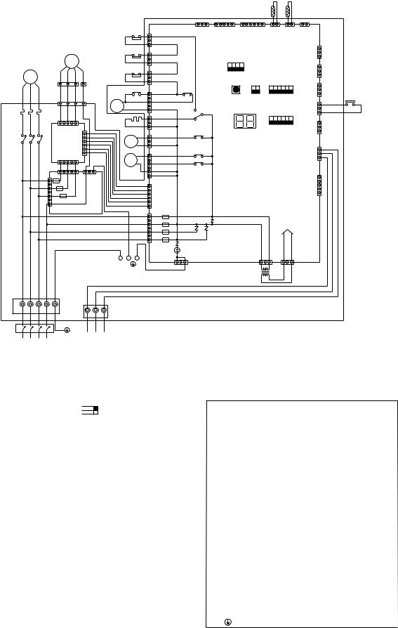
(3)System
Single
Indoor unit
3-core cable (DC12V)
Transmission line
Remote controller
Outdoor unit Pipe work
work
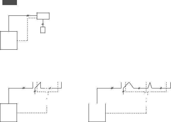
Twin |
|
|
|
Triple |
|
|
|
|
|
||||
|
|
Indoor units |
|
|
|
|
|
Indoor units |
|
||||
|
|
No. 1 |
|
|
No. 2 |
|
|
|
No. 1 |
|
No. 2 |
|
No.3 |
|
|
|
|
|
|
|
|
|
|
|
|
|
|
3-core cable (DC12V) |
Transmission |
3-core cable (DC12V) |
Transmission |
|
line |
|
line |
|
|
|
|
|
|
|
Distributor |
|
Remote |
|
|
|
Distributor |
||
|
|
|
|
|
|
|
|
|
|
|
|||||
|
|
|
|
|
|
|
|
|
|
|
controller |
|
|
|
|
Remote |
|
|
|
|
|
|
|
|
|
|
|
||||
controller |
|
|
|
|
|
|
|
|
|
|
|
||||
Outdoor unit |
Outdoor unit |
Pipe work |
Pipe work |
–7–
5Technical Data of PUH-8YE/10YE to Meet LVD
[1]Standard Operation Data
1 PUH-8YE
|
Operating condition |
|
|
Cooling |
|
|
Heating |
|
||
|
|
|
|
|
|
|
|
|
|
|
condition |
Voltage |
V |
380 |
400 |
415 |
380 |
400 |
415 |
||
|
|
|
|
|
|
|
|
|
||
Power source frequency |
Hz |
50 |
50 |
50 |
50 |
50 |
50 |
|||
|
|
|
|
|
|
|
|
|
||
Indoor air condition (DB/WB) |
°C |
27/19 |
27/19 |
27/19 |
20/– |
20/– |
20/– |
|||
|
|
|
|
|
|
|
|
|
||
Operating |
Outdoor air condition (DB/WB) |
°C |
35/- |
35/– |
35/– |
7/6 |
7/6 |
7/6 |
||
|
|
|
|
|
|
|
|
|
||
Piping length |
m |
7.5 |
7.5 |
7.5 |
7.5 |
7.5 |
7.5 |
|||
|
|
|
|
|
|
|
|
|
||
Refrigerant charge |
kg |
7.4 |
7.4 |
7.4 |
7.4 |
7.4 |
7.4 |
|||
|
||||||||||
|
|
|
|
|
|
|
|
|
|
|
characteristics |
|
Current |
A |
13.5 |
13.6 |
13.7 |
12.3 |
12.4 |
12.5 |
|
|
|
|
|
|
|
|
|
|
||
Outdoor unit |
Input |
kW |
7.62 |
7.62 |
7.62 |
6.91 |
6.91 |
6.91 |
||
|
|
|
|
|
|
|
|
|||
Compressor current |
A |
12.4 |
12.5 |
12.6 |
11.2 |
11.3 |
11.4 |
|||
|
||||||||||
|
|
|
|
|
|
|
|
|
||
|
Fan current |
A |
1.1 |
1.1 |
1.1 |
1.1 |
1.1 |
1.1 |
||
Electrical |
|
|||||||||
|
|
|
|
|
|
|
|
|
||
Indoor unit |
Current |
A |
1.12 |
1.12 |
1.12 |
1.12 |
1.12 |
1.12 |
||
|
|
|
|
|
|
|
|
|||
Input |
kW |
0.65 |
0.65 |
0.65 |
0.65 |
0.65 |
0.65 |
|||
|
||||||||||
|
|
|
|
|
|
|
|
|
|
|
|
Discharge pressure |
MPa |
1.99 |
1.99 |
1.99 |
1.59 |
1.59 |
1.59 |
||
circuit |
|
|
|
|
|
|
|
|
|
|
Suction pressure |
MPa |
0.49 |
0.49 |
0.49 |
0.35 |
0.35 |
0.35 |
|||
|
|
|
|
|
|
|
|
|
||
Discharge refrigerant temperature |
°C |
85 |
85 |
85 |
75 |
75 |
75 |
|||
Refrigerant |
||||||||||
|
|
|
|
|
|
|
|
|
||
Suction refrigerant temperature |
°C |
7 |
7 |
7 |
–2 |
–2 |
–2 |
|||
|
|
|
|
|
|
|
|
|
||
Liquid pipe temperature (at piping sensor) |
°C |
46 |
46 |
46 |
5 |
5 |
5 |
|||
|
|
|
|
|
|
|
|
|
||
Compressor shell bottom temperature |
°C |
50 |
50 |
50 |
35 |
35 |
35 |
|||
|
||||||||||
|
|
|
|
|
|
|
|
|
|
|
Note: The values listed above indicate that when connected with the indoor unit PEH-8YD as representative data.
2 PUH-10YE
|
Operating condition |
|
|
Cooling |
|
|
Heating |
|
||
|
|
|
|
|
|
|
|
|
|
|
condition |
Voltage |
V |
380 |
400 |
415 |
380 |
400 |
415 |
||
|
|
|
|
|
|
|
|
|
||
Power source frequency |
Hz |
50 |
50 |
50 |
50 |
50 |
50 |
|||
|
||||||||||
|
|
|
|
|
|
|
|
|
|
|
|
Indoor air condition (DB/WB) |
°C |
27/19 |
27/19 |
27/19 |
20/– |
20/– |
20/– |
||
Operating |
|
|
|
|
|
|
|
|
|
|
Outdoor air condition (DB/WB) |
°C |
35/- |
35/– |
35/– |
7/6 |
7/6 |
7/6 |
|||
|
||||||||||
|
|
|
|
|
|
|
|
|
|
|
|
Piping length |
m |
7.5 |
7.5 |
7.5 |
7.5 |
7.5 |
7.5 |
||
|
|
|
|
|
|
|
|
|
|
|
|
Refrigerant charge |
kg |
7.6 |
7.6 |
7.6 |
7.6 |
7.6 |
7.6 |
||
|
|
|
|
|
|
|
|
|
|
|
characteristics |
|
Current |
A |
16.8 |
16.9 |
17.0 |
14.8 |
14.9 |
15.0 |
|
|
|
|||||||||
|
|
|
|
|
|
|
|
|
|
|
|
Outdoor unit |
Input |
kW |
9.47 |
9.47 |
9.47 |
8.30 |
8.30 |
8.30 |
|
|
|
|
|
|
|
|
|
|
||
|
Compressor current |
A |
15.7 |
15.8 |
15.9 |
13.7 |
13.8 |
13.9 |
||
|
|
|||||||||
|
|
|
|
|
|
|
|
|
|
|
Electrical |
|
Fan current |
A |
1.1 |
1.1 |
1.1 |
1.1 |
1.1 |
1.1 |
|
|
|
|
|
|
|
|
|
|
||
|
Input |
kW |
0.94 |
0.94 |
0.94 |
0.94 |
0.94 |
0.94 |
||
|
Indoor unit |
Current |
A |
1.64 |
1.64 |
1.64 |
1.64 |
1.64 |
1.64 |
|
|
|
|
|
|
|
|
|
|
||
|
|
|
|
|
|
|
|
|
|
|
|
Discharge pressure |
MPa |
2.03 |
2.03 |
2.03 |
1.57 |
1.57 |
1.57 |
||
circuit |
|
|
|
|
|
|
|
|
|
|
Suction pressure |
MPa |
0.48 |
0.48 |
0.48 |
0.34 |
0.34 |
0.34 |
|||
|
||||||||||
|
|
|
|
|
|
|
|
|
|
|
Refrigerant |
Discharge refrigerant temperature |
°C |
95 |
95 |
95 |
80 |
80 |
80 |
||
|
|
|
|
|
|
|
|
|
||
Suction refrigerant temperature |
°C |
8 |
8 |
8 |
–2 |
–2 |
–2 |
|||
|
||||||||||
|
|
|
|
|
|
|
|
|
|
|
|
Liquid pipe temperature (at piping sensor) |
°C |
47 |
47 |
47 |
6 |
6 |
6 |
||
|
|
|
|
|
|
|
|
|
|
|
|
Compressor shell bottom temperature |
°C |
60 |
60 |
60 |
40 |
40 |
40 |
||
|
|
|
|
|
|
|
|
|
|
|
Note: The values listed above indicate that when connected with the indoor unit PEH-10YD as representative data.
–8–

[2] Cooling Capacity Curves
• PUH-8YE/10YE
1.4
|
|
Indo |
|
|
|
|
|
|
or inlet |
|
|
|
|
|
|
air |
|
|
|
|
|
|
w |
|
|
|
|
|
|
et |
|
|
|
|
|
|
b |
|
|
|
|
|
|
ul |
|
|
|
|
|
|
b |
|
|
|
|
|
|
t |
|
|
|
|
|
1.2 |
e |
mp. |
° |
|
|
|
|
|
|
< |
|
|
|
|
|
|
C |
|
|
|
|
|
|
|
W |
|
|
|
|
|
|
B |
|
|
|
|
|
|
> |
|
ratio |
|
|
|
|
|
|
|
|
|
|
|
|
|
|
|
|
|
22 |
||
Capacity |
1 |
|
|
|
||
|
|
|
|
20 |
||
|
|
|
|
|
||
|
|
|
|
|
|
|
|
|
|
|
|
|
|
|
0.8 |
|
|
|
|
18 |
|
|
|
|
|
||
|
|
|
|
|
|
|
|
|
|
|
16 |
||
|
|
|
|
|
||
0.6
-5 -3 -1 1 3 5 7 9 11 13 15 17 19 21 23 25 27 29 31 33 35 37 39 41 43 45 Outdoor air temp. <°CDB>
Input ratio
1.22
1.1
0.9
0.7
-5 -3 -1
22
20
18
16
|
|
|
|
|
|
|
|
|
|
> |
|
|
|
|
|
|
|
|
|
|
B |
|
|
|
|
|
|
|
|
|
|
W |
|
|
|
|
|
|
|
|
|
C |
|
|
|
|
|
|
|
|
|
° |
|
|
|
|
|
|
|
|
|
|
< |
|
|
|
|
|
|
|
|
|
. |
|
|
|
|
|
|
|
|
|
|
p |
|
|
|
|
|
|
|
|
|
|
m |
|
|
|
|
|
|
|
|
|
|
te |
|
|
|
|
|
|
|
|
|
|
lb |
|
|
|
|
|
|
|
|
|
|
u |
|
|
|
|
|
|
|
|
|
|
b |
|
|
|
|
|
|
|
|
|
t |
|
|
|
|
|
|
|
|
|
|
e |
|
|
|
|
|
|
|
|
|
w |
|
|
|
|
|
|
|
|
|
ir |
|
|
|
|
|
|
|
|
|
t |
a |
|
|
|
|
|
|
|
|
le |
|
|
|
|
|
|
|
|
|
r |
in |
|
|
|
|
|
|
|
|
oo |
|
|
|
|
|
|
|
|
|
|
Ind |
|
|
|
|
|
|
|
|
|
|
1 3 5 7 9 11 13 15 17 19 21 23 25 27 29 31 33 35 37 39 41 43 45 Outdoor air temp. <°CDB>
[3] |
Heating Capacity Curves |
||||||||||||||||||||
• PUH-8YE/10YE |
|
|
|
|
|
|
|
|
|
|
|
|
|
||||||||
|
1.4 |
|
|
|
|
|
|
|
|
|
|
|
|
|
|
|
|
|
|
|
15 |
|
|
|
|
|
|
|
|
|
|
|
|
|
|
|
|
|
|
|
|
||
|
|
|
|
|
|
|
|
|
|
|
|
|
|
|
|
|
|
|
|
|
|
|
|
|
|
|
|
|
|
|
|
|
|
|
|
|
|
|
|
|
|
|
|
|
|
|
|
|
|
|
|
|
|
|
|
|
|
|
|
|
|
|
|
|
|
|
|
|
|
|
|
|
|
|
|
|
|
|
|
|
|
|
|
|
|
|
20 |
|
|
|
|
|
|
|
|
|
|
|
|
|
|
|
|
|
|
|
|
|
|
|
1.2 |
|
|
|
|
|
|
|
|
|
|
|
|
|
|
|
|
|
|
|
25 |
|
|
|
|
|
|
|
|
|
|
|
|
|
|
|
|
|
|
|
|
||
|
|
|
|
|
|
|
|
|
|
|
|
|
|
|
|
|
|
|
|
|
|
|
|
|
|
|
|
|
|
|
|
|
|
|
|
|
|
|
> |
|
|
|
|
|
|
|
|
|
|
|
|
|
|
|
|
|
|
|
|
|
B |
|
|
|
|
ratio |
|
|
|
|
|
|
|
|
|
|
|
|
|
|
|
r |
D |
|
|
|
|
|
|
|
|
|
|
|
|
|
|
|
|
|
|
|
|
° |
|
|
|
|
|
|
|
|
|
|
|
|
|
|
|
|
|
|
|
|
|
|
C |
|
|
|
|
|
|
|
|
|
|
|
|
|
|
|
|
|
|
|
|
< |
|
|
|
|
|
|
|
|
|
|
|
|
|
|
|
|
|
|
|
|
|
e |
|
|
|
|
|
|
|
|
|
|
|
|
|
|
|
|
|
|
|
|
u |
|
|
|
|
||
|
|
|
|
|
|
|
|
|
|
|
|
|
|
|
t |
|
|
|
|
|
|
Capacity |
|
|
|
|
|
|
|
|
|
d |
|
|
|
a |
|
|
|
|
|
|
|
|
|
|
|
|
|
|
|
|
|
|
|
r |
|
|
|
|
|
|
|
||
|
1 |
|
|
|
|
|
|
|
|
|
|
|
|
e |
|
|
|
|
|
|
|
|
|
|
|
|
|
|
|
|
|
|
|
|
m |
p |
|
|
|
|
|
|
|
|
|
|
|
|
|
|
|
|
|
|
|
|
te |
|
|
|
|
|
|
|
|
|
|
|
|
|
|
|
|
|
|
|
|
|
lb |
|
|
|
|
|
|
|
|
|
|
|
|
|
|
|
|
|
|
|
|
u |
|
|
|
|
|
|
|
|
|
|
|
|
|
|
|
|
|
|
|
|
|
b |
|
|
|
|
|
|
|
|
|
|
|
|
|
|
|
|
|
|
|
|
y |
|
|
|
|
|
|
|
|
|
|
|
|
|
|
|
|
|
|
|
|
r |
|
|
|
|
|
|
|
|
|
|
|
|
|
|
|
|
|
|
|
|
|
ir |
|
|
|
|
|
|
|
|
|
|
|
|
|
|
|
|
|
|
|
|
a |
|
|
|
|
|
|
|
|
|
|
||
|
|
|
|
|
|
|
|
t |
|
|
|
|
|
|
|
|
|
|
|
|
|
|
|
|
|
|
|
|
|
le |
|
|
|
|
|
|
|
|
|
|
|
|
|
|
|
|
|
|
|
|
|
in |
|
|
|
|
|
|
|
|
|
|
|
|
|
|
|
|
|
|
|
|
r |
|
|
|
|
|
|
|
|
|
|
|
|
|
|
|
|
|
|
|
|
o |
|
|
|
|
|
|
|
|
|
|
|
|
|
|
|
|
|
|
|
|
o |
|
|
|
|
|
|
|
|
|
|
|
|
|
|
|
|
|
0.8 |
|
I |
d |
|
|
|
|
|
|
|
|
|
|
|
|
|
|
|
|
|
|
|
n |
|
|
|
|
|
|
|
|
|
|
|
|
|
|
|
|
|
||
|
0.6 |
|
|
|
|
|
|
|
|
|
|
|
|
|
|
|
|
|
|
|
|
|
|
|
|
|
|
|
|
|
|
|
|
|
|
|
|
|
|
|
|
|
|
|
|
|
|
|
|
|
|
|
|
|
|
|
|
|
|
|
|
|
|
|
|
|
|
|
|
|
|
|
|
|
|
|
|
|
|
|
|
|
|
|
|
|
|
|
|
|
|
|
|
|
|
|
|
|
|
|
|
|
|
|
|
|
|
|
|
|
-12 -10 -8 -6 -4 -2 0 2 4 6 8 10 12 14 15.5 |
||||||||||||||||||||
|
|
|
|
|
|
|
|
Outdoor air temperature <°CWB> |
|||||||||||||
|
1.4 |
|
|
|
|
|
|
|
|
|
|
|
|
|
|
|
|
25 |
|
|
|
|
|
|
|
|
|
|
|
|
|
|
|
|
|
||
|
|
|
|
|
|
|
|
|
|
|
|
|
|
|
|
|
|
|
|
|
|
|
|
|
|
|
|
|
|
|
|
|
|
|
|
|
|
|
|
|
|
|
|
|
|
|
|
|
|
|
|
|
|
|
|
|
|
|
|
|
|
|
|
|
|
|
|
|
|
|
|
|
|
|
|
|
1.2 |
|
|
|
|
|
|
|
|
|
|
|
|
|
|
|
|
20 |
|
|
|
|
|
|
|
|
|
|
|
|
|
|
|
|
|
||
|
|
|
|
|
|
|
|
|
|
|
|
|
|
|
|
|
|
|
|
|
|
|
|
|
|
|
|
|
|
° |
CDB> |
|
|
|
|
|
|
|
|
|
|
|
|
|
|
|
|
|
|
|
|
|
|
15 |
||
ratio |
|
|
|
|
|
|
|
|
|
|
< |
|
|
|
|
|
|
|
|
|
|
|
|
|
|
|
|
|
|
|
|
|
|
|
|
|
|
|
|
|
|
|
|
|
|
|
temperature |
|
|
|
|
|
|
|
|
|
Input |
1 |
|
|
|
|
|
|
|
|
|
|
|
|
|
|
|
|
|
|
|
|
|
|
|
bulb |
|
|
|
|
|
|
|
|
|
|
||
|
|
|
|
|
|
|
|
|
|
|
|
|
|
|
|
|
||
|
|
|
|
|
|
air |
dry |
|
|
|
|
|
|
|
|
|
|
|
|
|
|
|
|
|
|
|
|
|
|
|
|
|
|
|
|
|
|
|
|
|
|
|
inlet |
|
|
|
|
|
|
|
|
|
|
|
|
|
|
0.8 |
|
|
Indoor |
|
|
|
|
|
|
|
|
|
|
|
|
|
|
|
|
|
|
|
|
|
|
|
|
|
|
|
|
|
|
|
|
|
|
|
|
|
|
|
|
|
|
|
|
|
|
|
|
|
|
|
|
|
0.6 |
|
|
|
|
|
|
|
|
|
|
|
|
|
|
|
|
|
|
|
|
|
|
|
|
|
|
|
|
|
|
|
|
|
|
|
|
|
|
|
|
|
|
|
|
|
|
|
|
|
|
|
|
|
|
|
|
|
|
|
|
|
|
|
|
|
|
|
|
|
|
|
|
|
|
|
|
|
|
|
|
|
|
|
|
|
|
|
|
|
|
|
|
|
|
|
-10 -8 -6 -4 -2 0 2 4 6 8 |
10 12 14 15.5 |
|||||||||||||||
|
-12 |
|||||||||||||||||
Outdoor air temperature <°CWB>
–9–
 Loading...