


SPLIT-TYPE, HEAT PUMP AIR CONDITIONERS
July 2007
No.HWE07040
TECHNICAL & SERVICE MANUAL
[Model names]
PUH-8YKA
PUH-10YKA
CONTENTS
1. COMBINATION OF INDOOR AND OUTDOOR UNITS ···2
2. SAFETY FOR USE ·········································3
3. SAFETY PRECAUTIONS ·······························5
4. DATA ·······························································7
5. SOUND DATA ·················································8
6. OUTLINES AND DIMENSIONS ······················9
7. WIRING DIAGRAM ·······································10
8. REFRIGERANT SYSTEM DIAGRAM···········11
9. SYSTEM CONTROL ·····································12
10. TEST RUN ·····················································14
11. CONTROL ·····················································16
12. GROUP CONTROL ·······································29
13. NOTES FOR M-NET <MELANS> WIRING CONNECTION ····30
14. EMERGENCY OPERATION··························32
15. SELF-DIAGNOSIS AND TROUBLESHOOTING ···34
16. SIMPLE PARTS CHECK METHOD ··············45
17. PARTS NAME ···············································46
18. OPTIONAL PARTS ·······································48
1 COMBINATION OF INDOOR AND OUTDOOR UNITS
Types of connected indoor units
Outdoor unit |
|
Indoor unit |
|
|
|
|
|
Model name |
|
Service manual No. |
|
|
|
||
|
|
|
|
PUH-8YKA |
PEH-8GA |
|
HWE07030 |
PEH-16GA |
|
||
|
|
|
|
|
|
|
|
PUH-10YKA |
PEH-10GA |
|
HWE07030 |
PEH-20GA |
|
||
|
|
|
|
|
|
|
|
Outdoor Unit List
Specification |
|
|
|
Standard |
Salt-resistant |
Model name |
|
|
PUH-8YKA |
PUH-8YKA.TH |
PUH-8YKA.TH-BS |
|
|
|
PUH-10YKA |
PUH-10YKA.TH |
PUH-10YKA.TH-BS |
|
|
|
2
2 SAFETY FOR USE
Before conducting installation work, please read this ''SAFETY FOR USE'' carefully for correct installation.
Since the caution items shown here contain important description relative to safety, please observe them without fail.
Warning |
Erroneous handling gives a high possibility to induce serious results such as |
|
death or heavy injury. |
 Caution Erroneous handling may induce serious injury depending on the situation.
After reading, please keep it with you together the Instruction Manual, and read it again at the movement of the unit.
 Warning
The unit should not be installed by the user.
If the unit is installed improperly, explosion, water leakage, electric shock or fire may be result. Consult your dealer or specialist subcontractor for repair and movement.
For installation, conduct the work correctly by following the Installation Manual.
Improper installation may cause a fire, electrical shock or water leakage.
Install the unit on a spot sufficiently durable against the unit weight.
Insufficient durability can cause an injury by the falling down of unit.
All electric work must be performed by licensed technician, according to local regulations and the instructions given in this manual.
The units should be powered by dedicated power lines. Power lines with insufficient capacity or improper electrical work may result in electric shock or fire.
Use only the specified cables for wiring. The connections must be made secured without tension the terminals.
Improper connection or fastening can cause a fire or electrical shock.
The unit should be installed according to the instructions in order to minimize the risk of damage from earthquakes, typhoons or strong winds.
Improper installation work can cause an injury by the falling down of the unit.
The outdoor unit must be installed on stable, level surface, in a place where there is no accumulation of snow , leaves or rubbish.
The outdoor unit should be installed in a location where air and noise emitted by the unit will not disturb the neighbors. The indoor unit should be securely installed.
If the unit is loosely mounted, it may fall, and cause injury.
When installing or relocating the unit, make sure that no substance other than the specified refrigerant enters the refrigerant circuit.
Any presence of foreign substance such as air can cause abnormal pressure rise or explosion.
Never repair the unit, remodel or transfer it to another site by yourself.
If they are performed improperly, water leakage, electric shock or fire may result. If you need to have the unit repaired or moved, consult your dealer.
Use only the specified refrigerant (R-22) to charge the refrigerant circuit.
Do not mix it with any other refrigerant and do not allow air to remain in the circuit.
Air enclosed in the circuit can cause high pressure resulting in a rupture and other hazards.
Ventilate the room if refrigerant leaks during Installation.
The refrigerant heated generates poisonous gas by decomposition which can cause poisoning.
After completing installation work, make sure that refrigerant gas has not leaked.
If refrigerant gas has leaked and exposed to fan heater, stove, oven and so on, it may generate noxious gases.
Take a proper measure to suppress the critical concentration of refrigerant if leaked when installing the unit in a small room.
The limit density is made not to be exceeded even if the refrigerant leaks by any chance.
You are necessary to ventilation measures to prevent the accident. If the refrigerant leaks, hypoxia accident may caused.
For the countermeasure to be taken, consult your dealer.
The terminal block cover of unit must be firmly attached to prevent entry of dust and moisture.
Improper mounting of the cover cause electric shock or fire.
Use only optional parts authorised by Mitsubishi Electric.
If the accessories are installed improperly, water leakage, electric shock or fire may result.
Ask your dealer or an authorised company to install them.
3

 Caution
Never install on the place where a combustible gas might leak.
The gas may ignite or explode when the gas leaks and collects in surrounding of the unit.
When the unit is installed at telecommunication centers or hospitals, take a proper provision against noise.
The erroneous operation of air conditioner may be induced by inverter equipment, independent power device, medical equipment or communication equipment.
While the erroneous operation of medical equipment or communication equipment may caused by the air conditioner.
For special use as for foods, animals/plants, precision equipment or art objects, the applicability should be confirmed beforehand.
As the use for the applications other than that designed originally may result in the deterioration of the quality. Consult your dealer in this regard.
Do not use the unit under a special atmosphere.
Installing the unit at the following places may cause a trouble, a place where much machine oil, salt sonnet, humidity or dust, spa district, a place full of sulfur gas, volatile gas, or corrosive gas, a place near high frequency processing machine.
Thermal insulation of the drain pipes is necessary prevent dew condensation.
If the drain pipes are not properly insulated, condensation will result and drip on ceiling, floor or other possessions.
The drain piping must process by surely,and insulate the drain piping not to be dewy.
When the room humidity exceeds 80% or when the drain pipe is clogged, water may drip from the indoor unit. The outdoor unit produces condensation during the heating operation.
Make sure to provide drainage around the outdoor unit if such condensation is likely to cause damage.
Install drain piping according to this Installation Manual to ensure proper drainage.
Place thermal insulation on the pipes to prevent condensation.
Improper drain piping may cause water leakage and damage to furniture or other possessions.
The unit must be properly earth connected.
Do not connect the earth wire to gas pipe, city water pipe, lightning rod or telephone earth wire.
Improper earth connection may cause electrical shock.
When installing at a watery place, provide an electric leak breaker.
Failure to mount the electric leak breaker may cause electrical shock.
Use breaker or fuse with proper capacity. Make sure that there is a main power switch.
Using a wire or a copper wire instead of proper capacity of fuse can cause fire or trouble.
Other appliances connected to the same line could cause an overload.
For the power lines, use standard cables of sufficient current capacity.
Otherwise, current leakage, overheating or fire may occur.
When installing the power lines, do not apply tension to the cables.
The tighten or loosen the connections may cause generate heat and cause fire.
Remote controller is not pushed with the thing sharpening ahead.
It occasionally causes the electric shock and the breakdown.
Arrange the configuration of wiring not to bring up the panel and terminal cover, and fasten the panel and terminal cover securely.
The poor mounting of the panel or terminal cover may cause the heat generation of the terminal connection, a fire or electrical shock.
Do not wash the unit with water.
If washed with water, electrical shock may be caused.
Do not handle the switch with wet hands.
Otherwise electrical shock can be resulted.
Be very careful on handling the unit.
When carrying in outdoor unit, be sure to support it at four points.
Carrying in and lifting with 3-point support may make outdoor unit unstable, resulting in a fall of it.
The unit should not be carried by only one person if it is more than 20kg.
Some units use PP bands for packing.
Do not use any PP band for delivery purpose.
Do not touch the heat exchanger fins with your bear hands.
Doing so may cut your hands.
Be sure to safely dispose the packaging materials. Packaging materials, such as catches and other metal or wooden parts, may cause stabs or other injuries. Tear off and discard plastic packing bags so that children will not play any of them.
If children play with a plastic bag which was not torn off, it may cause a risk of suffocation.
Do not leave the mounting base being damaged.
The damaged base may cause the falling down of the unit which may give injury.
Turn on the main power switch more than 6 hours before starting operation.
Do not turn the main power switch OFF during seasons of heavy use, doing so can result in failure.
Do not touch the compressor or refrigerant piping without wearing glove on your hands.
Touching directly such part can cause a burn or frostbite as it becomes high or low temperature according to the refrigerant state.
Do not touch the metal edges inside the unit without wearing glove on your hands.
Touching directly it may injure your hands.
Do not remove the panel or the fan guard from the outdoor unit when it is running.
You could be injured if you touch rotating, hot or highvoltage parts.
Do not operate the air conditioner without the air filter set place.
Dust may accumulate, and cause a failure.
At emergency (if you smell something burning), stop operation and turn the power source switch off.
Continuing the operation without eliminating the emergency state may cause a machine trouble, fire, or electrical shock.
After stopping operation, be sure to wait for five minutes before turning off the main power switch.
Otherwise, water leakage or unit failure may occur.
Remote controller is not installed for the place where direct sunshine strikes.
4

3 SAFETY PRECAUTIONS
3-1. BEFORE INSTALLATION AND ELECTRIC WORK
sBefore installing the unit, make sure you read all the “Safety precautions”.
sThe “Safety precautions” provide very important points regarding safety. Make sure you follow them.
Symbols used in the text
 Warning:
Describes precautions that should be observed to prevent danger of injury or death to the user.
 Caution:
Describes precautions that should be observed to prevent damage to the unit.
Symbols used in the illustrations
: Indicates an action that must be avoided.
: Indicates that important instructions must be followed. : Indicates a part which must be grounded.
: Beware of electric shock. <Color: yellow>
 Warning:
Carefully read the labels affixed to the unit.
 Warning:
•Ask the dealer or an authorized technician to install the air conditioner.
-Improper installation by the user may result in water leakage, electric shock, or fire.
•Install the unit at a place that can withstand its weight.
-Inadequate strength may cause the unit to fall down, resulting in injuries.
•Use the specified cables for wiring. Make the connections securely so that the outside force of the cable is not applied to the terminals.
-Inadequate connection and fastening may generate heat and cause a fire.
•Prepare for strong winds and earthquakes and install the unit at the specified place.
-Improper installation may cause the unit to topple and result in injury.
•Always use an filter and other accessories specified by Mitsubishi Electric.
-Ask an authorized technician to install the accessories. Improper installation by the user may result in water leakage, electric shock, or fire.
•Never repair the unit. If the air conditioner must be repaired, consult the dealer.
-If the unit is repaired improperly, water leakage, electric shock, or fire may result.
•Do not touch the heat exchanger fins and metal edges.
-Improper handling may result in injury.
•If refrigerant gas leaks during installation work, ventilate the room.
-If the refrigerant gas comes into contact with a flame, poisonous gases will be released.
•Install the air conditioner according to this Installation Manual.
-If the unit is installed improperly, water leakage, electric shock, or fire may result.
•Have all electric work done by a licensed electrician according to “Electric Facility Engineering Standard” and “Interior Wire Regulations”and the instructions given in this manual and always use a special circuit.
-If the power source capacity is inadequate or electric work is performed improperly, electric shock and fire may result.
•Securely install the terminal cover (panel).
-If the terminal cover (panel) is not installed properly, dust or water may enter the outdoor unit and fire or electric shock may result.
•When installing and moving the air conditioner to another site, do not charge the it with a refrigerant different from the refrigerant (R22) specified on the unit.
-If a different refrigerant or air is mixed with the original refrigerant, the refrigerant cycle may malfunction and the unit may be damaged.
•If the air conditioner is installed in a small room, measures must be taken to prevent the refrigerant concentration from exceeding the safety limit even if the refrigerant should leak.
-Consult the dealer regarding the appropriate measures to prevent the safety limit from being exceeded. Should the refrigerant leak and cause the safety limit to be exceeded, hazards due to lack of oxygen in the room could result.
•When moving and reinstalling the air conditioner, consult the dealer or an authorized technician.
-If the air conditioner is installed improperly, water leakage, electric shock, or fire may result.
•After completing installation work, make sure that refrigerant gas is not leaking.
-If the refrigerant gas leaks and is exposed to a fan heater, stove, oven, or other heat source, it may generate noxious gases.
5
•Do not reconstruct or change the settings of the protection devices.
-If the pressure switch, thermal switch, or other protection device is shorted and operated forcibly, or parts other than those specified by Mitsubishi Electric are used, fire or explosion may result.
•To dispose of this product, consult your dealer.
•The installer and system specialist shall secure safety against leakage according to local regulation or standards.
-Following standards may be applicable if local regulation are not available.
•Pay a special attention to the place, such as a basement, etc. where refrigeration gas can stay, since refrigeration is heavier than the air.
•The appliance is not intended for use by young children or infirm persons without supervision.
•Young children should be supervised to ensure that they do not play with the appliance.
•Never operate in open phase condition. Control box may be broken.
3-2. BEFORE INSTALLATION
 Caution:
•Do not install the unit where combustible gas may leak.
-If the gas leaks and accumulates around the unit, an explosion may result.
•Do not use the air conditioner where food, pets, plants, precision instruments, or artwork are kept.
-The quality of the food, etc. may deteriorate.
•Do not use the air conditioner in special environments.
-Oil, steam, sulfuric smoke, etc. can significantly reduce the performance of the air conditioner or damage its parts.
•When installing the unit in a hospital, communication station, or similar place, provide sufficient protection against noise.
-The inverter equipment, private power generator, high-frequency medical equipment, or radio communication equipment may cause the air conditioner to operate erroneously, or fail to operate. On the other hand, the air conditioner may affect such equipment by creating noise that disturbs medical treatment or image broadcasting.
•Do not install the unit on a structure that may cause leakage.
-When the room humidity exceeds 80 % or when the drain pipe is clogged, condensation may drip from the indoor unit. Perform collective drainage work together with the outdoor unit, as required.
3-3. BEFORE INSTALLATION (MOVED) - ELECTRICAL WORK
 Caution:
•Ground the unit.
-Do not connect the ground wire to gas or water pipes, lightning rods, or telephone ground lines. Improper grounding may result in electric shock.
•The reverse phase of L lines (L1, L2, L3) can be detected (Error cord: 4103), but the reverse phase of L lines and N line can be not be detected.
-Some electric parts should be damaged when power is supplied under the miss wiring.
•Install the power cable so that tension is not applied to the cable.
-Tension may cause the cable to break and generate heat and cause a fire.
•Install an leak circuit breaker, as required.
-If an leak circuit breaker is not installed, electric shock may result.
•Use power line cables of sufficient current carrying capacity and rating.
-Cables that are too small may leak, generate heat, and cause a fire.
•Use only a circuit breaker and fuse of the specified capacity.
-A fuse or circuit breaker of a larger capacity or a steel or copper wire may result in a general unit failure or fire.
•Do not wash the air conditioner units.
-Washing them may cause an electric shock.
•Be careful that the installation base is not damaged by long use.
-If the damage is left uncorrected, the unit may fall and cause personal injury or property damage.
•Install the drain piping according to this Installation Manual to ensure proper drainage. Wrap thermal insulation around the pipes to prevent condensation.
-Improper drain piping may cause water leakage and damage to furniture and other possessions.
•Be very careful about product transportation.
-Only one person should not carry the product if it weighs more than 20 kg.
-Some products use PP bands for packaging. Do not use any PP bands for a means of transportation. It is dangerous.
-Do not touch the heat exchanger fins. Doing so may cut your fingers.
-When transporting the outdoor unit, suspend it at the specified positions on the unit base. Also support the outdoor unit at four points so that it cannot slip sideways.
•Safely dispose of the packing materials.
-Packing materials, such as nails and other metal or wooden parts, may cause stabs or other injuries.
-Tear apart and throw away plastic packaging bags so that children will not play with them. If children play with a plastic bag which was not torn apart, they face the risk of suffocation.

•Remote controller is not allowed to install for the place where direct sunshine strikes.
3-4. BEFORE STARTING THE TEST RUN
 Caution:
•Turn on the power at least 12 hours before starting operation.
-Starting operation immediately after turning on the main power switch can result in severe damage to internal parts. Keep the power switch turned on during the operational season.
•Do not touch the switches with wet fingers.
-Touching a switch with wet fingers can cause electric shock.
•Do not touch the refrigerant pipes during and immediately after operation.
-During and immediately after operation, the refrigerant pipes are may be hot and may be cold, depending on the condition of the refrigerant flowing through the refrigerant piping, compressor, and other refrigerant cycle parts. Your hands may suffer burns or frostbite if you touch the refrigerant pipes.
•Do not operate the air conditioner with the panels and guards removed.
-Rotating, hot, or high-voltage parts can cause injuries.
•Do not turn off the power immediately after stopping operation.
-Always wait at least five minutes before turning off the power. Otherwise, water leakage and trouble may occur.
•Do not operate the air conditioner without the air filter set place.
-Dust may accumulate, and cause a failure.
•At emergency (if you smell something burning), stop operation and turn the power source switch off.
-Continuing the operation without eliminating the emergency state may cause a machine trouble, fire, or electric shock.
•Remote controller should be pushed with finger.
-It occasionally causes the electric shock and the breakdown.
6

4 DATA
4-1. REFILLING REFRIGERANT CHARGE (R-22 : kg)
Model |
|
|
Piping length (one way) |
Additional refriferant charge (R22) |
kg |
|
|
|||||
7.5m |
10m |
15m |
20m |
|
25m |
30m |
35m |
|
40m |
45m |
50m |
|
|
|
|
||||||||||
PUH-8 |
0.0 |
0.3 |
0.9 |
1.5 |
|
2.1 |
2.6 |
3.2 |
|
3.8 |
4.4 |
5.0 |
PUH-10 |
0.0 |
0.3 |
0.9 |
1.5 |
|
2.1 |
2.6 |
3.2 |
|
3.8 |
4.4 |
5.0 |
Note:
If there is an insufficient amount of refrigerant in the system, the unit will behave in one of the following ways: 1) the discharge temperature of the unit rises abnormally high, which is detected as an error, and the unit comes to a stop; 2) the discharge temperature of the compressor rises abnormally high, the unit goes into the unload operation, which appears as the P8 error on the display, and the unit comes to a stop; or 3) the built-in thermostat on the compressor goes off and stops the compressor. In either case, replenish and adjust the refrigerant. Once the unit goes into the unload operation, it takes at least 3 hours until normal operation can be restored.
4-2. COMPRESSOR TECHNICAL DATA
|
|
|
at 20˚C |
Outdoor Unit |
|
PUH-8 |
PUH-10 |
Compressor Model |
|
ZR-94KC-TFD-501 |
ZR-125KC-TFD-501 |
Widing |
T1-T2 |
1.59 |
1.23 |
Resistance |
T2-T3 |
1.59 |
1.23 |
( ) |
T3-T1 |
1.59 |
1.23 |
7

5 |
|
|
|
SOUND DATA |
|
|
|
|
|
|
|
|
|
|||||
|
|
|
|
|
|
|
|
|
|
|
|
|
|
|
|
|
|
|
5-1. OUTDOOR UNITS |
|
|
|
|
|
|
|
|
|
|
|
|||||||
(1) Sound Levels |
|
|
|
|
|
|
|
|
|
|
|
|
|
|||||
|
|
|
|
|
|
|
|
|
|
|
|
|
|
|
|
|
|
|
Model |
|
SPL |
|
|
|
|
|
OCTAVE BAND FREQ.Hz |
|
|
|
|||||||
|
|
|
|
|
|
|
|
|
|
|
|
|
||||||
|
dB(A) |
|
63Hz |
|
125Hz |
250Hz |
|
500Hz |
1000Hz |
2000Hz |
4000Hz |
8000Hz |
|
|||||
|
|
|
|
|
|
|
|
|
|
|||||||||
|
|
|
|
|
|
|
|
|
|
|
|
|
|
|
|
|
||
PUH-8 |
|
Cool |
|
61 |
|
60 |
|
59 |
58 |
|
59 |
57 |
54 |
48 |
42 |
|
||
YKA |
Heat |
|
63 |
|
62 |
|
61 |
61 |
|
60 |
58 |
54 |
50 |
44 |
|
|||
|
|
|
|
|
|
|
|
|
|
|
|
|
|
|
|
|||
PUH-10 |
|
Cool |
|
61 |
|
59 |
|
59 |
59 |
|
59 |
57 |
53 |
49 |
42 |
|
||
YKA |
Heat |
|
63 |
|
60 |
|
60 |
62 |
|
62 |
58 |
54 |
49 |
43 |
|
|||
|
|
|
|
|
|
|
|
|
|
|
|
|
|
|
|
|
|
|
(2) Position measurement
PUH-8,10YKA
1m
Measurement point
0.75m
8
 Accessory
Conduit mouting plate
(Painted the same color as the unit body)
a) |
27 |
1pc. |
b) |
34 |
1pc. |
Tapping screw 4X12 |
4pcs. |
|
Connection pipe |
1pc. |
|
Packing. |
1pc |
|
Note 1.It is possible to change to 27 or |
34 by |
|
selecting the conduit mounting plate a,b.
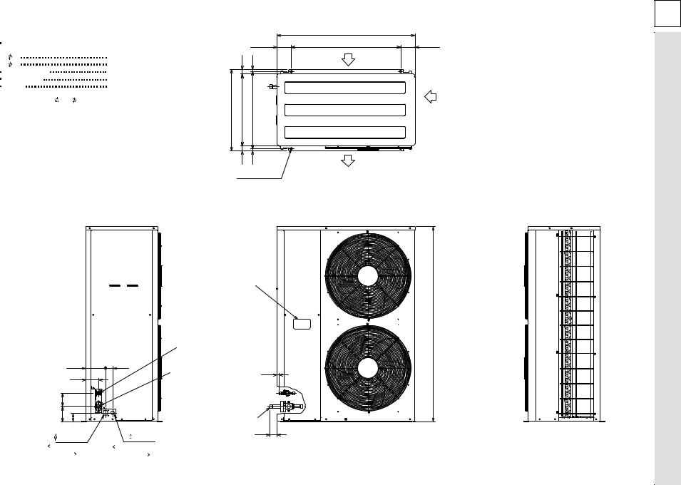
108.5
34 |
15 |
615 |
547 |
585 |
34 |
15 |
4-10X20 Holes  For mounting
anchor bolt M8 [Field supply]
9
|
152 |
55 |
|
97 |
|
100 |
|
|
115 |
65 |
|
Note 1 |
27 Hole |
|
40 Hole |
||
For the power |
For the indoor unit |
|
supply wiring |
connection wiring |
|
Left side view
Knock out hole Pressure gauge (For option)
Refrigerant pipe  15.88(5/8 flare)
Refrigerant pipe |
|
|
PU-8YAKD |
15 |
|
PUH-8YKA |
||
|
: 25.4 (1 flange) PU-10,12YAKD PUH-10YKA
: 28.6 (1-1/8 flange)
Connection pipe
(Accessory)
57
1047
830 |
108.5 |
Air inlet
Air inlet
Air outlet
Top view
1480
Front view |
Right side view |
10YKA-PUH 8YKA,-PUH
mm : Unit
DIMENSIONS AND OUTLINES 6

|
|
|
|
(*1) |
|
(*1) |
CH |
63H1 63L |
|
|
|
|
|
|
|
|
|
|
|
|
|
||||
|
MC |
MF2 |
|
|
MF3 |
SV1 |
|
|
|
|
|
|
|
|
|
|
|
|
|
||||||
|
|
|
21S4 |
|
|
|
|
|
|
|
|
|
|
|
|
|
|
|
|
||||||
|
White |
Black |
|
|
|
|
|
|
|
|
|
|
|
|
|
|
|
|
TH1 |
TH2 |
|
||||
Red |
|
|
|
|
|
|
|
|
|
|
|
|
|
|
|
|
|
|
|
|
|
|
|
||
|
|
|
|
|
|
|
|
|
|
|
|
|
|
|
|
|
|
|
|
|
2 1 |
|
|
2 1 |
|
|
|
|
|
|
|
|
|
51C |
|
1 |
CN23 |
CNVMNT |
CNMNT |
|
CN40 |
|
|
CN2 |
|
CN3 |
CN4 |
||||
|
|
|
|
|
|
|
|
|
|
|
|
|
|
|
|
|
|
|
|
|
|
||||
|
|
|
|
|
|
|
|
|
|
|
3 |
|
1 |
2 |
3 |
4 |
ON |
|
|
|
|
|
|
|
CN3D |
|
|
|
|
|
|
|
|
|
|
|
|
|
|
|
|
|
|
|
|
|
|
|
|
||
|
|
|
|
|
|
|
|
|
|
|
|
CN22 |
|
|
|
|
|
|
|
|
|
|
|
|
|
|
|
1 |
1 |
3 |
1 |
|
1 |
3 |
|
|
1 |
|
SW5 |
|
OFF |
|
|
|
|
|
|
|
|
||
|
|
|
|
|
3 |
|
|
|
|
|
|
|
|
|
|
|
|
||||||||
|
|
|
|
|
|
|
|
|
|
|
|
|
|
|
|
|
|
|
|
|
|
CN3S |
|||
|
|
|
|
|
|
|
|
|
|
|
|
|
|
|
|
|
|
|
|
|
|
|
|
||
|
|
C12 |
|
C11 C22 |
|
C21 |
|
|
|
|
|
|
|
|
1 |
2 |
1 |
2 |
3 |
4 |
5 |
6 |
|||
|
|
|
|
|
|
|
CN21 |
|
|
|
|
|
|||||||||||||
|
|
|
|
|
|
|
|
|
|
|
1 |
|
|
|
|
|
ON |
|
|
|
|
|
ON |
|
|
|
|
|
|
|
|
|
|
|
|
|
3 |
|
|
|
|
|
|
OFF |
|
|
|
|
|
OFF |
CN3N |
|
|
|
|
|
|
|
|
|
|
|
|
|
SW3 |
SW4 |
|
|
SW1 |
|
|
||||||
|
|
|
|
|
|
|
|
52C |
|
|
|
|
|
|
|
|
|||||||||
|
|
|
|
|
|
|
|
|
1 |
CN26 |
X04 |
|
|
|
|
|
1 |
2 |
3 |
4 |
5 |
6 |
|
||
|
|
|
|
|
|
|
|
|
|
|
|
|
|
|
|
|
|||||||||
|
|
|
|
|
|
|
|
|
|
|
|
|
|
|
|
|
|
|
|||||||
|
|
|
|
|
|
|
|
|
|
|
3 |
|
|
|
|
|
|
|
|
|
|
|
|
ON |
CN24 |
|
|
|
|
|
|
|
|
52C |
|
|
|
|
|
|
|
|
|
|
|
|
|
|
OFF |
||
|
|
|
|
|
|
|
|
|
|
5 |
|
X03 |
|
|
|
|
|
|
|
SW2 |
|
|
|||
51C |
|
|
|
|
|
|
|
|
|
|
|
|
|
|
|
|
|
|
|
|
|||||
|
|
|
|
|
|
|
|
|
|
|
CN25 |
|
|
|
|
|
|
|
|
|
|
|
|||
|
|
|
1 |
3 |
5 |
|
|
|
|
|
1 |
|
|
|
|
|
|
|
|
|
|
|
|
|
|
|
|
|
|
|
|
|
|
|
|
|
|
|
|
|
|
|
|
|
|
|
|
|
|||
|
|
|
CNFAN |
|
|
|
|
|
3 |
|
|
|
|
|
|
|
|
|
|
|
|
|
|
||
|
|
|
1 |
|
|
|
|
|
|
X01 |
|
|
|
|
|
|
|
|
|
|
|
|
|||
|
|
|
|
CNFC2 |
|
|
|
|
|
CN53 |
|
|
|
|
|
|
|
|
|
|
|
|
|||
52C |
|
|
|
|
|
|
|
|
|
|
|
|
|
|
|
|
|
|
|
|
|
|
|||
|
|
F.C. |
|
|
|
|
|
|
|
|
|
|
|
|
|
|
|
|
|
|
|
|
|
||
|
|
|
BOARD |
6 |
|
|
|
|
|
|
X02 |
|
|
|
|
|
|
|
|
|
|
|
|
||
|
|
|
|
|
|
|
|
|
|
1 |
CN52 |
|
|
|
M A I N B O A R D |
|
|
|
|
||||||
|
|
|
CNPOW |
|
|
|
|
|
|
|
|
|
|
|
|
||||||||||
|
|
|
|
|
|
|
|
3 |
|
X05 |
|
|
|
|
|
|
|
|
|
|
|
|
|||
|
|
|
|
|
|
|
|
|
|
|
|
|
|
|
|
|
|
|
|
|
|
|
|
||
10 |
|
CNOUT1 1 |
3 |
5 |
1 |
3 |
|
|
|
5 |
|
|
|
|
|
|
|
|
|
|
|
|
|
CN51 |
|
|
1 |
|
|
|
CNOUT2 |
|
|
6 |
|
|
|
|
|
|
|
|
|
|
|
|
|
||||
|
|
|
|
|
|
1 |
CNFC1 |
|
|
|
|
|
|
|
|
|
|
|
|
|
|||||
|
3 |
|
F10 |
|
|
|
|
|
|
|
|
|
|
|
|
|
|
|
|
|
|
|
|||
|
|
|
|
|
|
|
|
|
|
|
|
|
|
|
|
|
|
|
|
|
|
|
|
|
|
|
|
5 |
|
F20 |
|
|
|
|
|
|
|
|
|
|
|
|
|
|
|
|
|
|
|
|
|
|
|
|
|
|
|
|
|
|
|
|
|
|
|
|
|
|
|
|
|
|
|
|
|
|
|
|
|
7 |
|
F30 |
|
|
|
|
|
6 |
|
|
Transmission |
|
|
|
|
|
|
|
|||||
|
|
|
CNIN |
|
|
|
|
|
|
|
|
Circuit |
|
|
|
|
|
|
|
|
|
||||
|
|
|
N.F. BOARD |
|
L1 |
|
CN20 |
|
|
|
|
|
|
|
|
|
|
|
|
|
|||||
|
|
|
|
|
|
7 |
|
|
|
|
|
|
|
|
|
|
|
|
|
||||||
|
|
|
|
|
|
|
|
|
|
|
|
|
|
|
|
|
|
|
|
|
|
|
|||
|
|
|
|
|
|
|
|
|
|
N |
|
F01 |
|
|
|
|
|
|
|
|
DC power supply |
||||
|
|
|
|
|
|
|
|
|
|
|
|
|
|
|
|
|
|
|
|
||||||
|
|
|
|
|
|
|
|
|
|
L2 |
|
F04 |
|
|
|
|
|
|
|
|
|||||
|
|
|
|
|
|
|
|
|
|
|
|
|
|
|
|
|
|
|
|
|
|
|
|
||
Red |
White |
Black |
Blue |
F1 |
L3 |
1 |
F02 |
CNFG |
CNS3 |
CN28 |
|
|
CN34 |
|
X1 |
|
F03 |
|
|
||||||||||
|
|
|
|
Green/Yellow |
|
|
|
|
|
PRIMARY |
|
|
SECONDARY |
|
|
|
|
|
|
|
|
|
|
|
|
|
|||
|
|
|
|
F2 |
|
|
3 |
1 |
3 |
1 |
3 |
1 |
3 |
1 |
|
|
|
|
|
|
|
||||||||
TB1 |
|
|
|
|
|
|
|
|
|
|
TR |
|
|
|
|
|
|
TB3 |
TB8 |
|
|
|
|
|
|
|
|
|
|
L1 |
L2 |
L3 |
N |
|
|
|
|
|
|
|
|
|
||
S1 S2 S3 |
OUT OUT IN IN |
|
|
|
|
|
|
|
|
|
||||
|
|
|
|
|
|
|
|
|
|
|
|
|
||
CIRCUIT BREAKER |
|
|
|
|
|
|
|
|
|
OUTDOOR UNIT CONTROL BOX |
||||
|
|
|
|
|
|
|
|
|
|
|
|
|
|
|
(FIELD SUPPLY) |
|
|
|
|
TO INDOOR UNIT |
|
|
|
|
|
|
|
|
|
PUH-8,10YKA : 50A |
|
|
|
|
|
|
|
|
|
|
|
|
|
|
|
|
|
|
|
CONNECTING WIRES (*2) |
|
|
|
|
|
|
|
|
|
POWER SUPPLY |
PE |
(POLER) |
|
|
|
|
|
|
|
|
|
|||
|
|
|
|
|
|
|
|
|
|
|
||||
3N~PE |
|
|
|
INDOOR UNIT |
|
|
|
|
|
|
|
|||
380/400/415V |
|
|
|
|
|
|
|
|
||||||
50HZ |
|
|
|
|
|
|
|
|
|
|
|
|
|
|
|
OUTDOOR UNIT |
|
|
|
|
SYMBOL |
NAME |
||
|
F1,F2 |
FUSE (15A 250VAC CLASS T) |
||
|
51C |
|
OVER CURRENT RELAY (COMPRESSOR) |
|
|
52C |
|
MAGNETIC CONTACTOR (COMPRESSOR) |
|
|
63L |
|
PRESSURE SWITCH (LOW PRESSURE) |
|
|
63H1 |
|
PRESSURE SWITCH (HIGH PRESSURE) |
|
|
63H2 |
|
PRESSURE SWITCH (FOR CONTROL) |
|
|
MC |
|
COMPRESSOR MOTOR |
|
|
MF2,MF3 |
FAN MOTOR (OUTDOOR) |
||
|
TR |
|
TRANSFORMER |
|
|
X1 |
|
AUXILIARY RELAY |
|
|
21S4 |
|
4-WAY VALVE |
|
|
SV1 |
|
SOLENOID VALVE |
|
|
CH |
|
CRANK CASE HEATER (COMPRESSOR) |
|
|
TB1,3,8 |
TERMINAL BLOCK |
||
|
TH1 |
|
LIQUID PIPE TEMP |
|
X1 |
TH2 |
|
THERMISTOR DISCHARGE TEMP |
|
3 |
OUTDOOR |
F01-F04 |
FUSE (6.3A 250VAC CLASS F) |
|
1 |
||||
MAIN BOARD |
LED1 |
LED (FOR SERVICE) |
||
|
||||
|
|
X01-X05 |
AUXILIARY RELAY |
|
|
63H2 |
SW1-5 |
SWITCH |
|
3 |
CNVMNT |
CONNECTOR (CONNECT TO OPTIONAL M-NET ADAPTER BOARD) |
||
|
CNMNT |
CONNECTOR (CONNECT TO OPTIONAL M-NET ADAPTER BOARD) |
||
|
|
|||
1 |
|
CN40 |
CONNECTOR (LEV) |
|
|
|
CN4 |
CONNECTOR (THERMISTOR FOR COND/EVA TEMP) |
|
|
|
CN3D |
CONNECTOR (OPARATION) |
|
|
|
CN3N |
CONNECTOR (NIGHT MODE/SNOW SENSOR) |
|
|
|
CN51 |
CONNECTOR (EXTERNAL I/O) |
|
|
N.F.BOARD |
F10-F30 |
FUSE (6.3A 250VAC CLASS F) |
|
Note:1.The dotted lines show field wiring.
2.Color of earth wire is yellow and green twisting. 3.Specification subject to change without notice.
4.This motor(*1) includes auto reset type internal thermostat.
5.Indoor and outdoor connecting wires (*2) are made with polarities, make sure matching wiring and terminal.
6.mark is connector. mark is terminal.
Caution,
1.To protect compressor from abnormal current, over current relays is installed. Therefore, do not change factory set value of over current relays.
10YKA-PUH 8YKA,-PUH |
7 |
|
|
DIAGRAM WIRING |
|
|
|
11
|
|
|
|
|
8YKA-PUH |
|
|
|
|
|
10YKA-PUH |
|
|
Refrigerant flow in cooling |
R.V.coil |
||
|
|
Heating:ON |
|
||
|
|
Refrigerant flow in heating |
|
||
|
|
Cooling:OFF |
|
||
|
|
|
|
|
|
|
|
|
|
|
|
|
|
|
|
|
|
|
|
|
|
|
|
Indoor heat
exchanger
Thermistor
TH5
Thermistor
TH2
|
|
|
|
|
|
Outdoor heat exchanger |
|
|
|
|
|
|
|
|
|
|
|
4-wau value |
High pressure switch |
|
|
|
|
|
|
|
|
Brazing |
Flange |
Service |
(protection) |
|
|
|
|
|
|
|
|
|
|
|
|
|
|
|
|
|
|||
|
|
connection |
connection |
port |
Ball valve |
|
|
|
|
|
|
|
|
|
|
|
|
|
|
|
|
|
|
|
|
|
|
|
|
|
High pressure |
Capillary tube |
|
|
|
|
||
|
|
Refrigerant pipe |
|
switch (control) |
O.D. 6.0 |
× I.D. 4.0-L800 |
||||||
|
|
8HP:Ø25.4 |
|
|
Service port |
|
Capillary tube |
|
||||
|
|
10HP:Ø28.6mm |
|
Low pressure |
Service |
|
||||||
|
|
(with heat insulator) |
|
O.D. 6.0 |
× |
I.D. 4.0-L700 |
||||||
|
|
|
switch |
port |
|
|||||||
|
|
|
|
|
Solenoid valve Strainer |
|
|
|
|
|
|
|
|
Strainer |
|
Strainer |
|
Thermistor TH2 |
Thermistor |
|
|
|
|
|
|
Distributor |
|
|
(discharge temp) |
|
|
|
|
|
||||
|
|
|
|
|
|
TH1 |
|
|
|
|
|
|
|
|
|
|
|
|
|
(liquid temp) |
|
|
|
|
|
|
|
(with heat insulator) |
|
|
Compressor |
Restrictor |
Capillary |
|
|
|||
Restrictor |
|
|
|
tube |
|
|
|
|
||||
|
|
Accumulator |
valve |
|
|
|
|
|||||
|
Ø15.88mm |
|
Ball |
|
|
|
|
|
|
|||
valve |
|
|
|
|
PUH-8: |
|
|
|||||
|
Refrigerant pipe |
|
|
|
|
|
||||||
|
valve |
|
|
|
× I.D. 4.0-L14 |
|||||||
|
|
|
|
|
|
|
O.D. 6.0 |
|||||
|
|
|
Flared |
|
|
|
PUH-10: |
× |
|
|||
|
|
Brazing |
|
|
|
O.D. 6.0 |
|
I.D. 4.6-L15 |
||||
|
|
connection |
connection |
|
|
|
|
|
|
|
|
|
Capillary |
|
|
|
|
|
|
|
|
|
|
|
|
tube |
|
|
|
|
|
|
|
|
|
|
|
|
PEH-8: O.D. 4.0 × I.D. 3.0-L1000 |
|
|
|
|
|
|
|
|
|
|
||
PEH-10: O.D. 4.0 |
× I.D. 3.0-L700 |
|
|
|
|
|
|
|
|
|
|
|
DIAGRAM SYSTEM REFRIGERANT 8

9 
 SYSTEM CONTROL
9-1. OUTDOOR UNIT ADDRESS SETTINGS
• When controlling a group, the address must be set for each outdoor unit.
(SW1)
•During address setting, set all the dip switches SW1 (3 - 6) on the board to
<when shipped from factory: all OFF>. (Address setting is not necessary for |
|
|
|
|
OFF ON |
|
|
|
||||||||||||||||||||||
1:1 or Free multi-component systems.) |
|
|
|
|
|
|
|
|
|
|
|
|
|
|
|
1 |
|
|
|
|
|
|
|
|
|
|
|
|
||
|
|
|
|
|
|
|
|
|
|
|
|
|
|
|
2 |
|
|
|
|
|
|
|
|
|
|
|
|
|||
• Settings using SW1 are given below. |
|
|
|
|
|
|
|
|
|
|
|
|
|
|
|
|
|
|
|
|
|
|
|
|
|
|
|
|||
|
|
|
|
|
|
|
|
|
|
|
|
|
|
|
3 |
|
|
|
|
|
|
|
|
|
|
|
|
|||
|
|
|
|
|
|
|
|
|
|
|
|
|
|
|
|
|
|
|
|
|
|
|
|
|
|
|
||||
• Please set the mutually different address, and prevent the start up simultane- |
|
|
4 |
|
|
|
|
|
|
|
|
|
|
|
|
|||||||||||||||
|
|
|
|
|
|
|
|
|
|
|
|
|
|
|||||||||||||||||
|
|
5 |
|
|
|
|
|
|
|
|
|
|
|
|
||||||||||||||||
ously. (In case of connecting with PEH-16, 20) |
|
|
|
|
|
|
|
|
|
|
|
|
|
|
|
|
|
|
|
|
|
|
|
|
|
|
|
|||
|
|
|
|
|
|
|
|
|
|
|
|
|
|
|
6 |
|
|
|
|
|
|
|
|
|
|
|
|
|||
|
|
|
|
|
|
|
|
|
|
|
|
|
|
|
|
|
|
|
|
|
|
|
|
|
|
|
|
|
||
|
|
|
|
|
|
|
|
|
|
|
|
|
|
|
|
|
|
|
|
|
|
|
|
|
|
|
|
|
|
|
|
|
|
|
|
|
|
|
|
|
|
|
|
|
|
|
|
|
|
|
|
|
|
|
|
|
|
|
|
|
|
|
|
|
OFF |
ON |
|
|
|
OFF |
ON |
|
|
|
|
|
|
OFF |
|
ON |
|
|||||||||||
|
|
1 |
|
|
|
|
|
|
|
|
1 |
|
|
|
|
|
|
|
|
|
|
1 |
|
|
|
|
|
|
|
|
|
|
|
|
|
|
|
|
|
|
|
|
|
|
|
|
|
|
|
|
|
|
|
|
|
||||||
|
|
2 |
|
|
|
|
|
|
|
|
2 |
|
|
|
|
|
|
|
|
|
|
2 |
|
|
|
|
|
|
|
|
|
|
|
|
|
|
|
|
|
|
|
|
|
|
|
|
|
|
|
|
|
|
|
|
|
||||||
|
0 |
3 |
|
|
|
|
|
|
|
1 |
3 |
|
|
|
|
|
|
|
|
|
2 |
3 |
|
|
|
|
|
|
|
|
|
|
|
|
|
|
|
|
|
|
|
|
|
|
|
|
|
|
|
|
|
||||||||||
|
4 |
|
|
|
|
|
|
|
4 |
|
|
|
|
|
|
|
4 |
|
|
|
|
|
|
|
|
|||||
|
|
|
|
|
|
|
|
|
|
|
|
|
|
|
|
|
|
|
|
|
|
|
|
|
||||||
|
|
5 |
|
|
|
|
|
|
|
|
5 |
|
|
|
|
|
|
|
|
|
|
5 |
|
|
|
|
|
|
|
|
|
|
|
|
|
|
|
|
|
|
|
|
|
|
|
|
|
|
|
|
|
|
|
|
|
||||||
|
|
6 |
|
|
|
|
|
|
|
|
6 |
|
|
|
|
|
|
|
|
|
|
6 |
|
|
|
|
|
|
|
|
|
|
|
|
|
|
|
|
|
|
|
|
|
|
|
|
|
|
|
|
|
|
|
|
|
||||||
|
|
|
|
|
|
|
|
|
|
|
|
|
|
|
|
|
|
|
|
|
|
|
|
|
|
|
|
|
|
|
|
|
|
|
|
|
|
|
|
|
|
|
|
|
|
|
|
|
|
|
|
||||||||||
|
|
|
OFF |
ON |
|
|
|
OFF |
ON |
|
|
|
|
|
|
OFF |
|
ON |
|
|||||||||||
|
|
1 |
|
|
|
|
|
|
|
|
1 |
|
|
|
|
|
|
|
|
|
|
1 |
|
|
|
|
|
|
|
|
|
|
2 |
|
|
|
|
|
|
|
|
2 |
|
|
|
|
|
|
|
|
|
|
2 |
|
|
|
|
|
|
|
|
|
|
|
|
|
|
|
|
|
|
|
|
|
|
|
|
|
|
|
|
|
|
|
|
|
|
|
|
|||
|
8 |
3 |
|
|
|
|
|
|
|
9 |
3 |
|
|
|
|
|
|
|
10 |
3 |
|
|
|
|
|
|
|
|
||
|
|
|
|
|
|
|
|
|
|
|
|
|
|
|
|
|
|
|
|
|
|
|
||||||||
|
|
4 |
|
|
|
|
|
|
|
|
4 |
|
|
|
|
|
|
|
|
|
|
4 |
|
|
|
|
|
|
|
|
|
|
5 |
|
|
|
|
|
|
|
|
5 |
|
|
|
|
|
|
|
|
|
|
5 |
|
|
|
|
|
|
|
|
|
|
|
|
|
|
|
|
|
|
|
|
|
|
|
|
|
|
|
|
|
|
|
|
|
|
|
|
|||
|
|
6 |
|
|
|
|
|
|
|
|
6 |
|
|
|
|
|
|
|
|
|
|
6 |
|
|
|
|
|
|
|
|
|
|
|
|
|
|
|
|
|
|
|
|
|
|
|
|
|
|
|
|
|
|
|
|
|
|
|
|
|||
|
|
|
|
|
|
|
|
|
|
|
|
|
|
|
|
|
|
|
|
|
|
|
|
|
|
|
|
|
|
|
Operation by switch manipulation
|
|
|
|
|
|
|
|
|
|
Model |
|
|
|
|
|
|
ON |
|
|
|
|
|
|
|
|
OFF |
|
|
|
||||||||||||||
|
|
|
|
|
1 |
|
|
|
|
– |
|
|
|
|
|
|
|
|
|
|
|
|
– |
|
|
|
|
|
|
|
|
|
– |
|
|
|
|||||||
SW1function |
switching |
|
2 Error history clear |
|
|
|
|
|
Clear |
|
|
|
|
|
|
|
Ordinary |
|
|
|
|||||||||||||||||||||||
5 |
|
|
|
|
↑ |
|
|
|
|
|
|
|
|
|
|
|
|
|
Settings 0 - 15 |
|
|
|
|
|
|
|
|||||||||||||||||
|
|
|
|
|
|
3 Refrigerant system |
|
|
|
|
|
|
|
|
|
|
|
|
|
|
|
|
|
|
|
|
|
|
|
|
|
||||||||||||
|
|
|
|
|
|
|
|
address setting |
|
|
|
|
|
|
|
Outdoor unit address |
|
|
|
||||||||||||||||||||||||
|
|
|
|
|
4 |
|
|
|
|
↑ |
|
|
|
|
|
|
|
|
|
|
|
|
|
|
|
||||||||||||||||||
|
|
|
|
|
|
|
|
|
|
|
|
|
|
|
|
|
|
|
|
|
|
|
|
|
|
|
|
|
|
|
|
|
|
|
|
|
|
|
|||||
|
|
|
|
|
6 |
|
|
|
|
↑ |
|
|
|
|
|
|
|
|
|
|
|
|
|
|
|
|
|
|
|
|
|
|
|
|
|
|
|
|
|
|
|||
|
|
|
|
|
|
|
|
|
|
|
|
|
|
|
|
|
|
|
|
|
|
|
|
|
|
|
|
|
|
|
|
|
|
|
|
|
|
|
|
|
|
|
|
|
|
OFF |
ON |
|
|
|
OFF |
ON |
|
|
|
OFF |
ON |
|
|
|
OFF |
ON |
|
|
|
OFF |
ON |
||||||||||||||||||||
|
1 |
|
|
|
|
|
|
|
|
1 |
|
|
|
|
|
|
|
|
1 |
|
|
|
|
|
|
|
|
1 |
|
|
|
|
|
|
|
|
1 |
|
|
|
|
|
|
|
|
|
|
|
|
|
|
|
|
|
|
|
|
|
|
|
|
|
|
|
|
|
|
|
|
|
|
|
|
|
|
|
|||||||||||
|
2 |
|
|
|
|
|
|
|
|
2 |
|
|
|
|
|
|
|
|
2 |
|
|
|
|
|
|
|
|
2 |
|
|
|
|
|
|
|
|
2 |
|
|
|
|
|
|
|
|
|
|
|
|
|
|
|
|
|
|
|
|
|
|
|
|
|
|
|
|
|
|
|
|
|
|
|
|
|
|
|
|||||||||||
3 |
3 |
|
|
|
|
|
|
|
4 |
3 |
|
|
|
|
|
|
|
5 |
3 |
|
|
|
|
|
|
|
6 |
3 |
|
|
|
|
|
|
|
7 |
3 |
|
|
|
|
|
|
|
|
|
|
|
|
|
|
|
|
|
|
|
|
|
|
|
|
|
|
|
|
|
|
|
|
|
|||||||||||||||||
4 |
|
|
|
|
|
|
|
4 |
|
|
|
|
|
|
|
4 |
|
|
|
|
|
|
|
4 |
|
|
|
|
|
|
|
4 |
|
|
|
|
|
|
|||||
|
|
|
|
|
|
|
|
|
|
|
|
|
|
|
|
|
|
|
|
|
|
|
|
|
|
|
|
|
|
|
|||||||||||||
|
5 |
|
|
|
|
|
|
|
|
5 |
|
|
|
|
|
|
|
|
5 |
|
|
|
|
|
|
|
|
5 |
|
|
|
|
|
|
|
|
5 |
|
|
|
|
|
|
|
|
|
|
|
|
|
|
|
|
|
|
|
|
|
|
|
|
|
|
|
|
|
|
|
|
|
|
|
|
||||||||||||||
|
6 |
|
|
|
|
|
|
|
|
6 |
|
|
|
|
|
|
|
|
6 |
|
|
|
|
|
|
|
|
6 |
|
|
|
|
|
|
|
|
6 |
|
|
|
|
|
|
|
|
|
|
|
|
|
|
|
|
|
|
|
|
|
|
|
|
|
|
|
|
|
|
|
|
|
|
|
|
|
|
|
|||||||||||
|
|
|
|
|
|
|
|
|
|
|
|
|
|
|
|
|
|
|
|
|
|
|
|
|
|
|
|
|
|
|
|
|
|
|
|
|
|
|
|
|
|
|
|
|
|
|
|
|
|
|
|
|
|
|
|
|
|
|
|
|
|
|
|
||||||||||||||||||||||||
|
|
OFF |
ON |
|
|
|
OFF |
ON |
|
|
|
OFF |
ON |
|
|
|
OFF |
ON |
|
|
|
OFF |
ON |
||||||||||||||||||||
|
1 |
|
|
|
|
|
|
|
|
1 |
|
|
|
|
|
|
|
|
1 |
|
|
|
|
|
|
|
|
1 |
|
|
|
|
|
|
|
|
1 |
|
|
|
|
|
|
|
2 |
|
|
|
|
|
|
|
|
2 |
|
|
|
|
|
|
|
|
2 |
|
|
|
|
|
|
|
|
2 |
|
|
|
|
|
|
|
|
2 |
|
|
|
|
|
|
|
|
|
|
|
|
|
|
|
|
|
|
|
|
|
|
|
|
|
|
|
|
|
|
|
|
|
|
|
|
|
|
|
|
|
|
|
|
|
|||||
11 |
3 |
|
|
|
|
|
|
|
12 |
3 |
|
|
|
|
|
|
13 |
3 |
|
|
|
|
|
|
14 |
3 |
|
|
|
|
|
|
|
15 |
3 |
|
|
|
|
|
|
||
|
|
|
|
|
|
|
|
|
|
|
|
|
|
|
|
|
|
|
|
|
|
|
|
|
|
|
|
|
|
|
|
|
|||||||||||
|
4 |
|
|
|
|
|
|
|
|
4 |
|
|
|
|
|
|
|
|
4 |
|
|
|
|
|
|
|
|
4 |
|
|
|
|
|
|
|
|
4 |
|
|
|
|
|
|
|
5 |
|
|
|
|
|
|
|
|
5 |
|
|
|
|
|
|
|
|
5 |
|
|
|
|
|
|
|
|
5 |
|
|
|
|
|
|
|
|
5 |
|
|
|
|
|
|
|
|
|
|
|
|
|
|
|
|
|
|
|
|
|
|
|
|
|
|
|
|
|
|
|
|
|
|
|
|
|
|
|
|
|
|
|
|
|
|||||
|
6 |
|
|
|
|
|
|
|
|
6 |
|
|
|
|
|
|
|
|
6 |
|
|
|
|
|
|
|
|
6 |
|
|
|
|
|
|
|
|
6 |
|
|
|
|
|
|
|
|
|
|
|
|
|
|
|
|
|
|
|
|
|
|
|
|
|
|
|
|
|
|
|
|
|
|
|
|
|
|
|
|
|
|
|
|
|
|||||
|
|
|
|
|
|
|
|
|
|
|
|
|
|
|
|
|
|
|
|
|
|
|
|
|
|
|
|
|
|
|
|
|
|
|
|
|
|
|
|
|
|
|
|
9-2. EXAMPLES OF REFRIGERANT SYSTEM ADDRESS SETTING
<Standard setting>
Ex. |
Indoor unit |
Outdoor unit |
Outdoor unit refrigerant |
Remote controller |
|
|
|
system address |
power supply unit |
1 |
PEH-8, 10 |
– |
00 |
|
2 |
PEH-16, 20 |
No.1 |
00 |
|
|
|
No.2 |
01~15 |
X |
*Set the refrigerant system address of one outdoor unit to 00 for the power supply to the remote controller.
(The refrigerant system address is set to 00 when shipped from the factory.) Do not duplicate the refrigerant system address settings within the same system.
9-3. CAPACITY CONTROL SETTING METHOD (PEH-16, 20 ONLY)
With the PEH-16, 20 which has two outdoor units, the capacity can be controlled to 0%, 50% or 100%.
This is set by setting the outdoor unit side dip switches as shown in the table below before turning the power on.
|
No.1 side outdoor unit |
No.2 side outdoor unit |
|
|
|
DipSW5-1 |
OFF |
ON |
9-4. GROUPING BY USING LCD REMOTE CONTROLLER
Combination of indoor/outdoor unit can be controlled up to a maximum of 16 refrigerant systems.
* In case of PEH-8, 10 * In case of PEH-16, 20
|
|
E |
|
|
|
|
|
|
F |
|
|
|
G |
|
|
|
|
J |
|
|
E F |
|
G H |
|
|
I J |
|
|
|||||||||||||||||||||||||
|
|
|
|
|
|
|
|
|
|
|
|
|
|
|
|
|
|
|
|
|
|
|
|
|
|
|
|
|
|
|
|
|
|
|
|
|
|
|
|
|
|
|
|
|
|
|
|
|
|
|
|
|
|
|
|
A |
|
|
|
|
|
|
A |
|
|
|
A |
|
|
|
|
A |
|
|
A |
|
A |
|
|
A |
|
A |
|
|
A |
|
A |
|
|
||||||||||||||||||
|
|
|
|
|
|
|
|
|
|
|
|
|
|
|
|
|
No.1 |
|
No.2 |
|
|
|
No.1 |
|
No.2 |
|
|
No.1 |
|
No.2 |
|
|
|||||||||||||||||||||
|
|
|
|
|
|
|
|
|
|
|
|
|
|
|
|
|
|
|
|
|
|
|
|
|
|
|
|
|
|
|
|
|
|||||||||||||||||||||
|
|
|
|
|
|
|
|
|
|
|
|
|
|
|
|
|
|
|
|
|
|
|
|
|
|
|
|
|
|
|
|
|
|
|
|
|
|
|
|
|
|
|
|
|
|
|
|
|
|
|
|
A Outdoor unit |
B Indoor unit |
|
|
|
|
|
|
|
|
|
|
|
|
|
|
|
|
|
|
|
|
|
|
|
|
|
|
|
|
|
|
|
|
|
|
|
|
|
|
|
|
|
|
|
|
|
|
|
|
|
|
|
|
C Main remote controller |
D Subordinate remote controller |
|
|
B |
|
|
|
|
|
|
B |
2 |
|
B |
|
2 |
|
B |
|
|
|
|
B |
|
|
|
|
|
|
B |
|
2 |
|
|
B |
|
E Standard (Refrigerant address = 00) |
|
|||||||||||||||||
|
|
|
|
|
|
2 |
|
|
|
|
|
|
|
|
|
|
|
|
|
|
|
|
|
|
|
|
2 |
|
|
|
|
|
|
|
|
|
|
|
|
|
|
|
|
||||||||||
|
|
|
|
|
|
|
|
|
|
|
|
|
|
|
|
|
|
|
|
|
|
|
|
|
|
|
|
|
|
|
|
|
|
|
|
|
|
|
|
|
|
|
|
|
|
|
F Refrigerant address = 01 |
G Refrigerant address = 02 |
|||||
|
|
|
|
|
1 |
|
|
|
|
|
|
|
|
|
|
|
|
|
|
|
|
|
|
|
|
|
|
|
|
1 |
|
|
|
|
|
|
|
|
|
|
|
|
|
|
|
|
|
|
|||||
|
|
|
|
|
|
|
|
|
|
|
|
|
|
|
|
|
|
|
|
|
|
|
|
|
|
|
|
|
|
|
|
|
|
|
|
|
|
|
|
|
|
|
|
|
|
H Refrigerant address = 03 |
I Refrigerant address = 14 |
||||||
|
|
|
|
|
|
|
|
|
|
|
|
|
|
|
|
|
|
|
|
|
|
|
|
|
|
|
|
|
|
|
|
|
|
|
|
|
|
|
|
|
|
|
|
|
|||||||||
|
|
C |
|
|
|
|
D |
1 |
|
|
|
|
|
|
|
|
|
|
|
|
|
C |
|
|
|
|
|
D |
|
1 |
|
|
|
|
|
|
|
|
|
|
J Refrigerant address = 15 |
|
|||||||||||
|
|
|
|
|
|
|
|
|
|
|
|
|
|
|
|
|
|
|
|
|
|
|
|
|
|
|
|
|
|
|
|
|
|
|
|
|
|
|
|
|
|
|
|
|
|
|
|
|
|
|
|
|
|
12
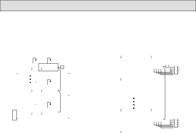
1 Wiring from the Remote Control
This wire is connected to TB5 (terminal board for remote controller) of the indoor unit (non-polar).
2 When a Different Refrigerant System Grouping is Used
Up to 16 refrigerant systems can be controlled as one group using the LCD remote controller.
Notes:
1.In single refrigerant system, there is no need of wiring 2.
2.LCD remote controller can be installed up to a maximum of 2 units for one group.
Grouping (16 outdoor units) [Example: PEH-8, 10] |
|
|
|
|
|
|
|
|
Grouping (16 outdoor units) [Connecting with PEH-16, 20] |
|
|
|
|
|
|
|
|
|
|
|
|
|
|||||||||||||||||||||||||||||||||||||||||||||||||||||||||||||||||||||||||||||||||||||||
|
|
|
|
|
|
|
|
|
|
|
|
|
|
|
|
|
|
|
|
|
|
|
|
|
|
|
|
|
|
|
|
|
|
|
|
|
|
|
|
|
|
|
|
|
|
|
|
|
|
|
|
|
|
|
|
|
|
|
|
|
|
|
|
|
|
|
|
|
|
|
|
|
|
|
|
|
|
|
|
|
|
|
|
|
|
|
|
|
|
|
|
|
|
|
|
|
|
|
|
||||||||||
|
|
|
|
|
|
|
|
|
|
|
|
|
|
|
|
|
|
|
|
|
|
|
|
|
|
|
|
|
|
|
|
|
|
|
|
|
|
|
|
|
|
|
|
|
|
|
|
|
|
|
|
|
|
|
|
|
|
|
|
|
|
|
|
|
|
|
|
|
|
|
|
|
|
|
|
|
|
|
|
|
|
|
|
|
|
|
|
|
|
|
|
|
|
|
|
|
|
|
|
|
|
|
|
|
|
|
|
|
|
|
|
|
|
|
|
|
|
|
|
|
|
|
|
|
|
|
|
|
|
|
|
|
|
|
|
|
|
|
|
|
|
|
|
|
|
|
|
|
|
|
|
|
|
|
|
|
|
|
|
|
|
|
|
|
|
|
|
|
|
|
|
|
|
|
|
|
|
|
|
|
|
|
|
|
|
|
|
|
|
|
|
|
|
|
|
|
|
|
|
|
|
|
|
|
|
|
|
|
|
|
|
|
|
|
|||||
|
|
|
|
|
|
|
|
|
|
|
|
|
|
|
|
|
|
|
|
|
|
|
|
|
|
|
|
|
|
|
|
|
|
|
|
|
|
|
|
|
|
|
|
|
|
|
|
|
|
|
|
|
|
|
|
|
|
|
|
|
PUH-8, 10 |
|
|
|
|
|
|
|
|
|
|
|
PEH |
-16, 20 |
|
|
|
|
|
|
|
|
|||||||||||||||||||||||||||
|
|
|
|
|
|
|
|
|
|
|
|
|
|
|
|
|
|
|
|
|
|
|
|
|
|
|
|
|
|
|
|
|
|
|
|
|
|
|
|
|
|
|
|
|
|
|
|
|
|
|
|
|
|
|
|
|
|
|
|
|
F (00) |
|
|
|
|
|
|
|
|
|
|
|
|
E |
|
|
|
|
|
|
|
|
|
|
|
|
|
||||||||||||||||||||||
|
|
|
|
|
|
|
|
|
PUH-8, 10 |
|
|
|
PEH-8, 10 |
|
|
|
|
|
|
|
|
|
|
|
|
|
|
|
|
|
|
|
|
|
|
|
|
|
|
|
|
|
|
|
|
|
|
|
|
|
|
|
|
|
|
|
|
|
|
|
|
(TB4-1) (TB4-2) |
|
|
|
|
|
|
|
|
|
|
|
|
|
||||||||||||||||||||||||||||||||||
|
|
|
|
|
|
|
|
|
|
|
|
F(00) |
|
|
|
|
|
|
|
E |
|
|
|
|
|
|
|
D |
|
|
|
|
|
|
|
|
|
|
|
|
|
|
|
|
|
L1 |
L2 |
L3 |
N |
S1 |
|
S2 |
S3 |
OUT |
|
OUT |
|
IN |
IN |
|
|
|
|
S1 |
S2 |
S3 |
|
S1 |
S2 |
S3 |
|
L1 |
L2 |
L3 |
N |
|
|
D |
|
|
|
||||||||||||||||||||||||||||
A |
|
B |
|
C |
|
|
|
|
L1 |
L2 |
L3 |
N |
S1S2 |
S3 |
|
|
S1S2 |
S3 |
|
L1 |
L2 |
L3 |
N |
|
|
|
|
|
C |
|
B |
|
A A |
|
B |
|
C |
|
|
|
|
|
|
|
|
|
|
|
|
|
|
|
|
|
|
|
|
|
|
|
|
|
|
|
|
|
|
|
|
|
|
|
|
|
|
|
|
|
|
|
|
|
|
|
|
|
|
|
|
|
|
|
|
C |
B |
|
A |
||||||||||||
|
|
|
|
|
|
|
|
|
|
|
|
|
|
|
|
|
|
|
|
|
|
|
|
|
|
|
|
|
|
|
|
|
|
|
|
|
|
|
|
|
|
|
|
|
|
|
|
|
|
|
|
|
|
|
|
|
|
|
|
|
|
|
|
|
|
|
|
|
|
|
|
||||||||||||||||||||||||||||||||||||||
|
|
|
|
|
|
|
|
|
|
|
|
|
|
|
|
|
|
|
|
|
|
|
|
|
|
|
|
|
|
|
|
|
|
|
|
|
|
|
|
|
|
|
|
|
|
|
|
|
|
|
|
|
|
|
|
|
|
|
|
|
|
|
|
|
|
|
|
|
|
|
|
|
|
|
|
|
|
|
|
|
|
|
|
|
|
|
|
|
|
|
|
|
|
|
|
|
|
|
|
|
|
|
|
|
|
|
|
|
|
|
|
|
|
|
|
|
|
|
|
|
|
|
|
|
|
|
|
|
|
|
|
|
|
|
|
|
|
|
|
|
|
|
|
|
|
|
|
|
|
|
|
|
|
|
|
|
|
|
|
|
|
|
|
|
|
|
|
|
|
|
|
|
|
|
|
|
|
|
|
|
|
|
|
|
|
|
|
|
|
|
|
|
|
|
|
|
|
|
|
|
|
|
|
|
|
|
|
|
|
|
|
|
|
|
|
|
|
|
|
|
|
|
|
|
|
|
|
|
|
|
|
|
|
|
|
|
|
|
|
|
|
|
|
|
|
|
|
|
|
|
|
|
|
|
|
|
|
|
|
|
|
|
|
|
|
|
|
|
|
|
|
|
|
|
|
|
|
|
|
|
|
|
|
|
|
|
|
|
|
|
|
|
|
|
|
|
|
|
|
|
|
|
|
|
|
|
|
|
|
|
|
|
|
|
|
|
|
|
|
|
|
|
|
|
|
|
|
|
|
|
|
|
|
|
|
|
|
|
|
|
|
|
|
|
|
|
|
|
|
|
|
|
|
|
|
|
|
|
|
|
|
|
|
|
|
|
|
|
|
|
|
|
|
|
|
|
|
|
|
|
|
|
|
|
|
|
PUH-8, 10 |
|
|
|
|
|
|
|
|
|
|
|
|
|
|
|
|
|
|
|
|
|
|
|
|
|
|
|
|
|
|
|
|
|
|
|
|
|
|
|
|
||||||||||||
|
|
|
|
|
|
|
|
|
|
|
|
|
|
|
|
|
|
|
|
|
|
|
|
|
|
|
|
|
|
|
|
|
|
|
|
|
|
|
|
|
|
|
|
|
|
|
|
|
|
|
|
|
|
|
|
|
|
|
F (01) |
|
|
|
|
|
|
|
|
|
|
|
|
|
|
|
|
|
|
|
|
|
|
|
|
|
|
|
|
|
|
|
|
|
|
|
|
|
|
|
|
||||||||||
|
|
|
|
|
|
|
|
|
PUH-8, 10 |
|
|
|
|
PEH-8, 10 |
|
|
|
|
|
|
|
|
|
|
|
|
|
|
|
|
|
|
|
L1 |
L2 |
L3 |
N |
S1 |
S2 |
S3 |
OUT |
OUT |
IN |
IN |
|
|
|
|
|
|
|
|
|
|
|
|
|
|
|
|
|
|
|
|
|
|
|
|
|
|
|
|
|
|
|||||||||||||||||||||||||||||||||||
|
|
|
|
|
|
|
|
|
|
|
|
|
|
|
|
|
|
|
|
|
|
|
|
|
|
|
|
|
|
|
|
|
|
|
|
|
|
|
|
|
|
|
|
|
|
|
|
|
|
|
|
|
|
|
|
|
|
|
|
|
|
||||||||||||||||||||||||||||||||||||||||||||||||
|
|
|
|
|
|
|
|
|
|
|
|
F(14) |
|
|
|
|
|
|
|
E |
|
|
|
|
|
|
|
|
|
|
|
|
|
|
|
A |
|
B |
|
C |
|
|
|
|
|
|
|
|
|
|
|
|
|
|
|
|
|
|
|
|
|
|
|
|
|
|
|
|
|
|
|
|
|
|
|
|
|
|
|
|
|
|
|
|
|
|
|
|
|
|
|
|
|
|
|
|
|
|
|
|
|
||||||||
|
|
|
|
|
|
|
|
|
L1 |
L2 |
L3 |
N |
S1S2 |
S3 |
|
|
S1S2 |
S3 |
|
L1 |
L2 |
L3 |
N |
|
|
|
|
|
C |
|
B |
|
A |
|
|
|
|
|
|
|
|
|
|
|
|
|
|
|
|
|
|
|
|
|
|
|
|
|
|
|
|
|
|
|
|
|
|
|
|
|
|
|
|
|
|
|
|
|
|
|
|
|
|
|
|
|
|
|
|
|
|
|
|
|
|
|
|
|
|||||||||||
|
|
|
|
|
|
|
|
|
|
|
|
|
|
|
|
|
|
|
|
|
|
|
|
|
|
|
|
|
|
|
|
|
|
|
|
|
|
|
|
|
|
|
|
|
|
|
|
|
|
|
|
|
|
|
|
|
|
|
|
|
|
|
|
|
|
|
|
|
|
|
|
|
|
|
|
|
|
|
|
|
|
|
|
||||||||||||||||||||||||||
A |
|
B |
|
C |
|
|
|
|
|
|
|
|
|
|
|
|
|
|
|
|
|
|
|
|
|
|
|
|
|
|
|
|
|
|
|
|
|
|
|
|
|
|
|
|
|
|
|
|
|
|
|
|
|
|
|
|
|
|
|
|
|
|
|
|
|
|
|
|
|
|
|
|
|
|
|
|
|
|
|
|
|
|
|
|
|
|
|
|
|
|
|
|
|
|
|
|
|
|
|
|
|
|
|
|
|
|
|||
|
|
|
|
|
|
|
|
|
|
|
|
|
|
|
|
|
|
|
|
|
|
|
|
|
|
|
|
|
|
|
|
|
|
|
|
|
|
|
|
|
|
|
|
|
|
|
|
|
|
|
|
|
|
|
|
|
|
|
|
|
|
|
|
|
|
|
|
|
|
|
|
|
|
|
|
|
|
|
|
|
|
|
|
|
|
|
|
|
|
|
|
|
|
|
|
|
|
|
|
|
|
|
|
|
|
|
|
|
|
|
|
|
|
|
|
|
|
|
|
|
|
|
|
|
|
|
|
|
|
|
|
|
|
|
|
|
|
|
|
|
|
|
|
|
|
|
|
|
|
|
|
|
|
|
|
|
|
|
|
|
|
|
|
|
|
|
|
|
|
|
|
|
|
|
|
|
|
|
|
|
|
|
|
|
|
|
|
|
|
|
|
|
|
|
|
|
|
|
|
|
|
|
|
|
|
|
|
|
|
|
|
|
|
|
|
|
|||
|
|
|
|
|
|
|
|
|
|
|
|
|
|
|
|
|
|
|
|
|
|
|
|
|
|
|
|
|
|
|
|
|
|
|
|
|
|
|
|
|
|
|
|
|
|
|
|
|
|
|
|
|
|
|
|
|
|
|
|
|
|
|
|
|
|
|
|
|
|
|
|
|
|
|
|
|
|
|
|
|
|
|
|
|
|
|
|
|
|
|
|
|
|
|
|
|
|
|
|
|
|
|
|
|
|
|
|
|
|
|
|
|
|
|
|
|
|
|
PUH-8, 10 |
|
|
|
|
PEH-8, 10 |
|
|
|
|
|
|
|
|
|
|
|
|
|
|
|
|
|
|
|
|
|
|
|
|
|
|
|
|
|
|
|
|
|
|
|
|
|
|
|
|
|
|
|
|
|
|
|
|
|
|
|
|
|
|
|
|
|
|
|
|
|
|
|
|
|
|
|
|
|
|
|
|
|
|
|||||||||||||||||||||
|
|
|
|
|
|
|
|
|
|
|
|
|
|
|
|
|
|
|
|
|
|
|
|
|
|
|
|
|
|
|
|
|
|
|
|
|
|
|
|
|
|
|
|
|
|
|
|
|
|
|
|
|
|
|
|
|
|
|
|
|
|
|
|
|
|
|
|
|
|
|
|
|
|
|
|
|
|
|
|
|
|
|
|
||||||||||||||||||||||||||
|
|
|
|
|
|
|
|
|
|
|
|
F (15) |
|
|
|
|
|
|
E |
|
|
|
|
|
|
|
|
|
|
|
|
|
|
|
|
|
|
|
|
|
|
|
|
|
|
|
|
|
|
|
|
|
|
|
|
|
|
|
|
|
|
|
|
|
|
|
|
|
|
|
|
|
|
|
|
|
|
|
|
|
|
|
|
|
|
|
|
|
|
|
|
|
|
|
|
|
|
|
|
|
|||||||||
|
|
|
|
|
|
|
|
|
L1 |
L2 |
L3 |
N |
S1S2 |
S3 |
|
|
S1S2 |
S3 |
|
L1 |
L2 |
L3 |
N |
|
|
|
|
|
C |
|
B |
|
A |
|
|
|
|
|
|
|
|
|
|
|
|
|
|
|
|
PUH-8, 10 |
|
|
|
|
|
|
|
|
|
|
|
PEH |
-16, 20 |
|
|
|
|||||||||||||||||||||||||||||||||||||||||||
A |
|
B |
|
C |
|
|
|
|
|
|
|
|
|
|
|
|
|
|
|
|
|
|
|
|
|
|
|
|
|
|
|
||||||||||||||||||||||||||||||||||||||||||||||||||||||||||||||||||||||||||||||
|
|
|
|
|
|
|
|
|
|
|
|
|
|
|
|
|
|
|
|
|
|
|
|
|
|
|
|
|
|
|
|
|
|
|
|
|
|
|
|
|
|
|
|
|
|
|
|
|
|
|
|
|
|
|
|
|
|
|
|
|
|
|
|
F (14) |
|
|
|
|
|
|
|
|
|
|
|
|
|
|
|
E |
|
|
|
|
|
|
|
|
|
|
|
|
|
||||||||||||||||
|
|
|
|
|
|
|
|
|
|
|
|
|
|
|
|
|
|
|
|
|
|
|
|
|
|
|
|
|
|
|
|
|
|
|
|
|
|
|
|
|
|
|
|
|
|
|
|
|
|
|
|
|
|
|
|
|
|
|
|
|
|
|
|
|
|
|
|
|
|
|
|
|
|
|
|
|
|
|
|
|
|
|
|
(TB4-1) (TB4-2) |
|
|
|
|
|
|
|
|
|
|
|
|
|
||||||||||||
|
|
|
|
|
|
|
|
|
|
|
|
|
|
|
|
|
|
|
|
|
|
|
|
|
|
|
|
|
|
|
|
|
|
|
|
|
|
|
|
|
|
|
|
|
|
|
|
|
|
|
|
|
|
|
|
|
|
|
|
|
|
|
|
|
|
|
|
|
|
|
|
|
|
|
|
|
|
|
|
|
|
|
|
|
|
|
|
|
|
|
|
|
|||||||||||||||||
|
|
|
|
|
|
|
|
|
|
|
|
|
|
|
|
|
|
|
|
|
|
|
|
|
|
|
|
|
|
|
|
|
|
|
|
|
|
|
|
|
|
|
|
|
|
|
|
|
|
|
|
|
|
|
|
|
|
|
|
|
|
|
|
|
|
|
|
|
|
|
|
|
|
|
|
|
|
|
|
|
|
|
|
|
|
|
|
|
|
|
|
|
|
|
|
|
|
|
|
|
|
|
|
|
|
|
|
|
|
|
|
|
|
|
|
|
|
|
|
|
|
|
|
|
|
|
|
|
|
|
|
|
|
|
|
|
|
|
|
|
|
|
|
|
|
|
|
|
|
|
|
|
|
A |
|
B |
|
C |
|
|
|
|
L1 |
L2 |
L3 |
N |
S1 |
|
S2 |
S3 |
OUT |
OUT |
IN |
IN |
|
|
|
|
S1 |
S2 |
S3 |
|
S1 |
S2 |
S3 |
|
L1 |
L2 |
L3 |
N |
|
|
|
|
B |
|
A |
||||||||||||||||||||||
|
|
|
|
|
|
|
|
|
|
|
|
|
|
|
|
|
|
|
|
|
|
|
|
|
|
|
|
|
|
|
|
|
|
|
|
|
|
|
|
|
|
|
|
|
|
||||||||||||||||||||||||||||||||||||||||||||||||||||||||||||||||
|
|
|
|
|
|
|
|
|
|
|
|
|
|
|
|
|
|
|
|
|
|
|
|
|
|
|
|
|
|
|
|
|
|
|
|
|
|
|
|
|
|
|
|
|
|
|
|
|
|
|
|
|
|
|
|
|
|
|
|
|
|
|
|
|
|
|
|
|
|
|
|
|
|
|
|
|
|
|
|
|
|
|
|
|
|
|
|
|
|
|
|
|
|
|
|
|
|
|
|
|
|
C |
|
||||||
|
|
|
|
|
|
|
|
|
|
|
|
|
|
|
|
|
|
|
|
|
|
|
|
|
|
|
|
|
|
|
|
|
|
|
|
|
|
|
|
|
|
|
|
|
|
|
|
|
|
|
|
|
|
|
|
|
|
|
|
|
|
|
|
|
|
|
|
|
|
|
|
|
|
|
|
|
|
|
|
|
|
|
|
|
|
|
|
|
|
|
|
|
|
|
|
|
|
|
|
|
|
|
|
||||||
|
|
|
|
|
|
|
|
|
|
|
|
|
|
|
|
|
|
|
|
|
|
|
|
|
|
|
|
|
|
|
|
|
|
|
|
|
|
|
|
|
|
|
|
|
|
|
|
|
|
|
|
|
|
|
|
|
|
|
|
|
|
|
|
|
|
|
|
|
|
|
|
|
|
|
|
|
|
|
|
|
|
|
|
|
|
|
|
|
|
|
|
|
|
|
|
|
|
|
|
|
|
|
|
|
|
|
|
|
|
|
|
|
|
|
|
|
|
|
|
|
|
|
|
|
|
|
|
|
|
|
|
|
|
|
|
|
|
|
|
|
|
|
|
|
|
|
|
|
|
|
|
|
|
|
|
|
|
|
|
|
|
|
|
|
|
|
|
|
|
|
|
|
|
|
|
|
|
|
|
|
|
|
|
|
|
|
|
|
|
|
|
|
|
|
|
|
|
|
|
|
|
|
|
|
|
|
|
|
|
|
|
|
|
|
|
|
|
|
|
|
|
|
|
|
|
|
|
|
|
|
|
|
|
|
|
|
|
|
|
|
|
|
|
|
|
|
|
|
|
|
|
|
|
|
|
|
|
|
|
|
|
|
|
|
|
|
|
|
|
|
|
|
|
|
|
|
PUH-8, 10 |
|
|
|
|
|
|
|
|
|
|
|
|
|
|
|
|
|
|
|
|
|
|
|
|
|
|
|
|
|
|
|
|
|
|
|
|
|
|
|
|
||||||||||||
|
|
|
|
|
|
|
|
|
|
|
|
|
|
|
|
|
|
|
|
|
|
|
|
|
|
|
|
|
|
|
|
|
|
|
|
|
|
|
|
|
|
|
|
|
|
|
|
|
|
|
|
|
|
|
|
|
|
F (15) |
|
|
|
|
|
|
|
|
|
|
|
|
|
|
|
|
|
|
|
|
|
|
|
|
|
|
|
|
|
|
|
|
|
|
|
|
|
|
|
|
|||||||||||
|
|
|
|
|
|
|
|
|
|
|
|
|
|
|
|
|
|
|
|
|
|
|
|
|
|
|
|
|
|
|
|
|
|
|
|
|
|
|
|
|
|
|
|
A |
|
B |
|
C |
|
|
|
|
|
|
L1 |
L2 |
L3 |
N |
S1 |
S2 |
S3 |
OUT |
|
OUT |
|
IN |
|
IN |
|
|
|
|
|
|
|
|
|
|
|
|
|
|
|
|
|
|
|
|
|
|
|
|
|
|
|
|
|
|
|||||||||||
|
A Power supply |
|
|
|
|
|
B Earth leakage breaker |
C Circuit breaker or local switch |
|
|
|
D Remote controller |
|
E Indoor unit |
|
F Outdoor unit (Address) |
|||||||||||||||||||||||||||||||||||||||||||||||||||||||||||||||||||||||||||||||||||||||||||||
13

10 
 TEST RUN
10-1. OUTDOOR UNIT
(1) Test run
The test run can be carried out from the outdoor unit.
1. Checklist
•After the installation, piping setup, and wiring of the indoor and outdoor units is complete, check that refrigerant is not leaking, the power and control wires are not loose, and the poles are not reversed.
•Use a 500 V insulation resistance tester to make sure that the resistance be-
tween the power terminal and the ground is 1.0 MΩ or more. If it is less than 1.0 MΩ , do not operate the unit. * Absolutely do not touch the tester to indoor/ outdoor connection terminals S1, S2, and S3. An accident could occur.
•Make sure there is no malfunction in the outdoor unit. (If there is a malfunction, you can diagnose it using LED1 on the board.)
•Check that the ball valve is fully open on both the liquid and gas ends.
•Check to make sure that L1, L2, and L3 are connected in the correct phase order. Connecting them in the reverse order will trip the negative-phase protector, and the unit will come to a stop, displaying the Error code F1.
•Starting at least 12 hours before the test run, send current through the crankcase heater. (If the current is running for a shorter period of time, damage to the compressor could result.)
After the above checks are complete, carry out the test run as indicated in the following outline.
2. Starting and finishing the test run
•Procedure from the outdoor unit: start and stop the test run and set test run mode (cooling/heating) using the SW4 dip switches on the board.
1 Set test run mode (cooling/heating) using SW 4-2.
2 The test run will begin when SW 4-1 is turned ON, according to the mode selected by SW 4-2.
3 The test run is stopped when SW 4-1 is turned OFF.
|
|
|
|
|
<SW4> |
|
|
||||||
stop |
|
|
OFF |
|
ON |
|
run |
||||||
|
|
|
|
|
|
|
|||||||
|
|
|
1 |
|
|
|
|
|
|
|
|
|
|
|
|
|
2 |
|
|
|
|
|
|
|
|
|
|
cooling |
|
|
|
|
|
|
|
|
|
|
|
|
heating |
Note:
Test run mode cannot be stopped during operation by using SW 4-2. (If the operation mode is to be changed, first stop it using SW 4-1, then after changing the operation mode, start the test run again using SW 4-1.)
•If the 2-hour timer is set, the test run will stop automatically after 2 hours.
•During the test run, the room temperature display on the indoor unit will indicate the temperature of the indoor unit piping.
•When you operate the test run from OC1, all trial runs are completed by OC1
→ IC1 → MA → IC1 → OC2.
(IC1) |
|
PEH-16, 20 |
|
MA |
|||||
|
|||||||||
|
|
|
|
|
|
|
|
|
|
|
|
OC1 |
|
OC2 |
|
|
|
||
(2) How to handle problems with the test run
• Error code list: details
Remote controller |
MELANS display |
Error details |
Problem location |
|
display |
||||
|
|
|
||
E0 |
6831,6834 |
Remote controller communication – reception error |
Remote Controller |
|
E1, E2 |
6201,6202 |
Remote controller board error |
Remote Controller |
|
E3 |
6832,6833 |
Remote controller communication – transmission error |
Remote Controller |
|
E4 |
6831,6834 |
Remote controller communication – reception error |
Indoor unit |
|
E5 |
6832,6833 |
Remote controller communication – transmission error |
Indoor unit |
|
E6 |
6740,6843 |
Communication between indoor and outdoor units – reception error |
Indoor unit |
|
E7 |
6841,6842 |
Communication between indoor and outdoor units – transmission error |
Indoor unit |
|
E8 |
6840,6843 |
Communication between indoor and outdoor units – reception error |
Outdoor unit |
|
E9 |
6841,6842 |
Communication between indoor and outdoor units – transmission error |
Outdoor unit |
|
|
|
|
|
|
EA |
6844 |
Indoor/outdoor connection wiring error, indoor unit overload (5 units or more) |
Outdoor unit |
|
|
|
|
|
|
EB |
6845 |
Indoor/outdoor connection wiring error (interference, loose) |
Outdoor unit |
|
EC |
6846 |
Excessive time in use |
Outdoor unit |
|
ED |
0403 |
Serial communication error |
Outdoor unit |
|
EE |
0403 |
Serial communication error |
M-NET board |
|
F1 |
4103 |
Reverse phase, out of phase verification |
Outdoor unit |
|
F8 |
4115 |
Faulty input circuit |
Outdoor unit |
|
A0 |
6600 |
Duplicated M-NET address setting |
M-NET board |
|
A2 |
6602 |
M-NET error in PH/W transmission |
M-NET board |
|
A3 |
6603 |
M-NET bus busy |
M-NET board |
|
A6 |
6606 |
M-NET communication error with P transmission |
M-NET board |
|
A7 |
6607 |
M-NET error – no ACK |
M-NET board |
|
A8 |
6608 |
M-NET errorno response |
M-NET board |
|
EF |
undefined |
Undefined error code |
– |
|
U2 |
1102 |
Outlet temperature error |
Outdoor unit |
|
U2 |
1108 |
CN23 Short-circuit Connector Unplugged |
Outdoor unit |
|
U3 |
5104 |
Open/short in discharge temp thermistor |
Outdoor unit |
|
U4 |
5105 |
Open/short in liquid temp thermistor |
Outdoor unit |
|
U6 |
4101 |
Compressor overcurrent interruption (51C operation) |
Outdoor unit |
|
UE |
1302 |
High pressure error (63H1 operation) |
Outdoor unit |
|
UL |
1300 |
Low pressure error (63L operation) |
Outdoor unit |
|
F8 |
4115 |
Power synchronous idle circuit error |
Outdoor unit |
|
P1 |
5101 |
Inlet sensor error |
Indoor unit |
|
P2 |
5102 |
Open/short in liquid temp thermistor |
Indoor unit |
|
P4 |
2503 |
Drain sensor error |
Indoor unit |
|
P5 |
2502 |
Drain overflow protector operation |
Indoor unit |
|
P5 |
2500 |
Water leak error (PDH only) |
Indoor unit |
|
P6 |
1503 |
Freeze prevention operation |
Indoor unit |
|
P6 |
1504 |
Surge prevention operation |
Indoor unit |
|
P8 |
1110 |
Piping temperature error |
Indoor unit |
|
|
|
|
|
|
P9 |
5103 |
Open/short in condenser/evaporater temp thermistor |
Indoor unit |
14

•Depending on the position of the SW2 switch on the outdoor unit board, the segments light up to indicate the running condition of the unit and the particulars of the check code.
SW2 setting |
Item |
|
|
|
|
Display contents |
|
|
|
|
|
|
|
|
|
||||||||||||||||||
123456 |
|
|
|
|
|
|
|
|
|
|
|
|
|
||||||||||||||||||||
|
|
|
|
|
|
|
|
|
|
|
|
|
|
|
|
|
|
|
|
|
|
|
|
|
|
|
|
|
|
|
|
|
|
000000 |
Operation mode/relay output |
|
tens place |
O: stop |
|
|
|
|
|
|
|
|
|
|
|
|
|
|
|
|
|
|
|
|
|
|
|
|
|
|
|
|
|
|
|
|
|
C: cooling |
|
|
|
|
|
|
|
|
|
|
|
|
|
|
|
|
|
|
|
|
|
|
|
|
|
|
|
|
|
|
|
|
|
H: heating |
|
|
|
|
|
|
|
|
|
|
|
|
|
|
|
|
|
|
|
|
|
|
|
|
|
|
|
|
|
|
|
|
|
d: defrosting |
|
|
|
|
|
|
|
|
|
|
|
|
|
|
|
|
|
|
|
|
|
|
|
|
|
|
|
|
|
|
|
|
units place |
1: SV1 |
|
|
Relay output = SV1 + 21S4 + 52C |
|
|
|
|
|
|
|
|
|
|||||||||||||||||
|
|
|
|
2: 21S4 |
|
|
|
|
|
|
|
|
|
|
|
||||||||||||||||||
|
|
|
|
|
|
|
|
|
|
|
|
|
|
|
|
|
|
|
|
|
|
|
|
|
|
|
|
|
|
|
|
|
|
|
|
|
|
4: 52C |
|
|
|
|
|
|
|
|
|
|
|
|
|
|
|
|
|
|
|
|
|
|
|
|
|
|
|
|
|
|
|
|
|
|
|
|
Ex. During cooling mode, when 52C and SV1 are ON: C5 |
||||||||||||||||||||||||||
|
|
|
When an error occurs, the error code |
|
|
|
|
|
|
|
|
|
|
|
|
|
|
|
|
|
|
|
|
|
|
|
|
|
|
|
|
|
|
|
|
|
and error signal (*1) are displayed in |
|
|
|
|
|
|
|
|
|
|
|
|
|
|
|
|
|
|
|
|
|
|
|
|
|
|
|
|
|
|
|
|
|
alternation. |
|
|
|
|
|
|
|
|
|
|
|
|
|
|
|
|
|
|
|
|
|
|
|
|
|
|
|
|
|
|
|
|
|
|
|
|
|
|
|
|
|
|
|
|
|
|
|
|
|
|
|
|
|
|
|
|
|
|
|
|
|
|
|
|
011110 |
Outdoor unit control condition |
|
Control mode display system |
|
|
|
|
|
|
|
|
|
|
|
|
|
|
|
|
|
|
|
|
|
|
|
|
|
|
|
|
|
|
|
|
Display |
|
|
|
|
|
|
|
|
|
|
Control mode |
|
|||||||||||||||||||
|
|
|
|
|
|
|
|
|
|
|
|
|
|
|
|
|
|||||||||||||||||
|
|
(IC1) |
|
|
|
|
|
|
|
|
|
|
|
|
|
Indoor unit |
|
Outdoor unit |
|
||||||||||||||
|
|
|
|
|
|
|
|
|
|
|
|
|
|
|
|
|
|
|
|
|
|
|
|
|
|
|
|
|
|
|
|
|
|
010110 |
Indoor unit control condition |
|
|
|
|
0 |
|
|
|
|
|
|
|
Ordinary |
|
|
|
|
← |
|
|||||||||||||
(IC2) |
|
|
|
|
|
|
|
|
|
|
|
|
|
|
|||||||||||||||||||
|
|
|
|
|
|
|
|
|
|
|
|
|
|
|
|
|
|
|
|
|
|
|
|
|
|
|
|
|
|
|
|
|
|
|
|
|
|
|
|
1 |
|
|
|
|
|
Hot adjustment |
|
|
|
|
← |
|
|||||||||||||||
|
|
|
|
|
|
|
|
|
|
|
|
|
|
|
|||||||||||||||||||
|
|
|
|
|
|
|
|
|
|
|
|
|
|
|
|
|
|
|
|
|
|
|
|
|
|
|
|
|
|
|
|
|
|
|
|
|
|
|
|
|
2 |
|
|
|
|
|
|
|
Defrosting |
|
|
|
|
← |
|
||||||||||||
|
|
|
|
|
|||||||||||||||||||||||||||||
|
|
|
|
|
|
|
|
|
|
|
|
|
|
|
|
|
|
|
|
|
|
|
|
|
|
|
|
|
|
|
|
|
|
|
|
|
Indoor unit No.2 |
Indoor unit No.1 |
|
|
3 |
|
|
|
|
|
|
|
|
— |
|
|
|
|
← |
|
|||||||||||
|
|
|
|
Indoor unit No.3 |
|
|
|
|
|
|
|
|
|
|
|
|
|
|
|
|
|
|
|
|
|
|
|
|
|
|
|
|
|
110110 |
|
(IC3) |
Indoor unit No.4 |
|
|
4 |
|
|
|
|
|
|
Heater ON |
|
|
|
|
← |
|
||||||||||||||
Indoor unit control condition |
|
Outdoor unit |
|
|
|
|
|
|
|
|
|
|
|
|
|
|
|
|
|
|
|
|
|
|
|
|
|
|
|
|
|
||
|
|
|
5 |
|
|
|
|
|
Freeze prevention |
|
|
|
|
← |
|
||||||||||||||||||
(IC4) |
|
|
|
|
|
|
|
|
|
|
|
||||||||||||||||||||||
|
|
|
|
|
|
|
|
|
|
|
|
|
|
||||||||||||||||||||
|
|
|
|
|
|
|
|
|
|
|
|
|
|
|
|
|
|
|
|
|
|
|
|
|
|
|
|
|
|
|
|
|
|
|
|
|
|
|
|
|
6 |
|
|
|
|
|
Surge prevention |
|
|
|
|
← |
|
||||||||||||||
|
|
|
|
|
|
|
|
|
|
|
|
|
|
|
|
|
|
|
|
|
|
|
|
|
|
|
|
|
|
|
|
|
|
|
|
|
|
|
|
|
7 |
|
|
|
|
|
Compressor OFF |
|
|
|
|
← |
|
||||||||||||||
|
|
|
|
|
|
|
|
|
|
|
|
|
|
|
|
|
|
|
|
|
|
|
|
|
|
|
|
|
|
|
|
|
|
011100 |
Error code history 1 |
|
The error code (ex. U8, UA) and error indicator (*1) are displayed in alternation. |
|
|
|
|
|
|
|
|
|
|||||||||||||||||||||
|
|
|
|
|
|
|
|
|
|
|
|
||||||||||||||||||||||
111100 |
Error code history 2 |
|
|
|
|
|
|
|
|
|
|
||||||||||||||||||||||
|
|
|
|
|
|
|
|
|
|
|
|
|
|
|
|
|
|
|
|
|
|
|
|
|
|
|
|
|
|
|
|
||
|
|
|
|
|
|
|
|
|
|
|
|
|
|
|
|
|
|
|
|
|
|
|
|
|
|
|
|
|
|
|
|
|
|
*1 Display system for error indicator
The indicator corresponds to the following numbers
0 |
............. Outdoor unit |
1 |
............. Indoor unit No.1 |
2 |
............. Indoor unit No.2 |
3 |
............. Indoor unit No.3 |
4 |
............. Indoor unit No.4 |
15
 Loading...