


PU-3VJC.UK
TECHNICAL & SERVICE MANUAL
SPLIT -TYPE AIR CONDITIONERS
CONTENTS
1.
COMBINATION OF INDOOR AND OUTDOOR UNITS
····2
2. PART NAMES AND FUNCTIONS ···················2
3. SPECIFICATIONS············································2
4. DATA ································································3
5. OUTLINES AND DIMENSIONS·······················4
6. WIRING DIAGRAM ··········································5
7. REFRIGERANT SYSTEM DIAGRAM··············5
8. DISASSEMBLY PROCEDURE ························6
9. PARTS LIST·····················································8
10. OPTIONAL PARTS ·······································10
Outdoor unit
[Model names]
PU-3VJC
PU-3YJC
[Service Ref.]
PU-3VJC.UK
PU-3YJC.UK
No.OC202
Outdoor unit
2
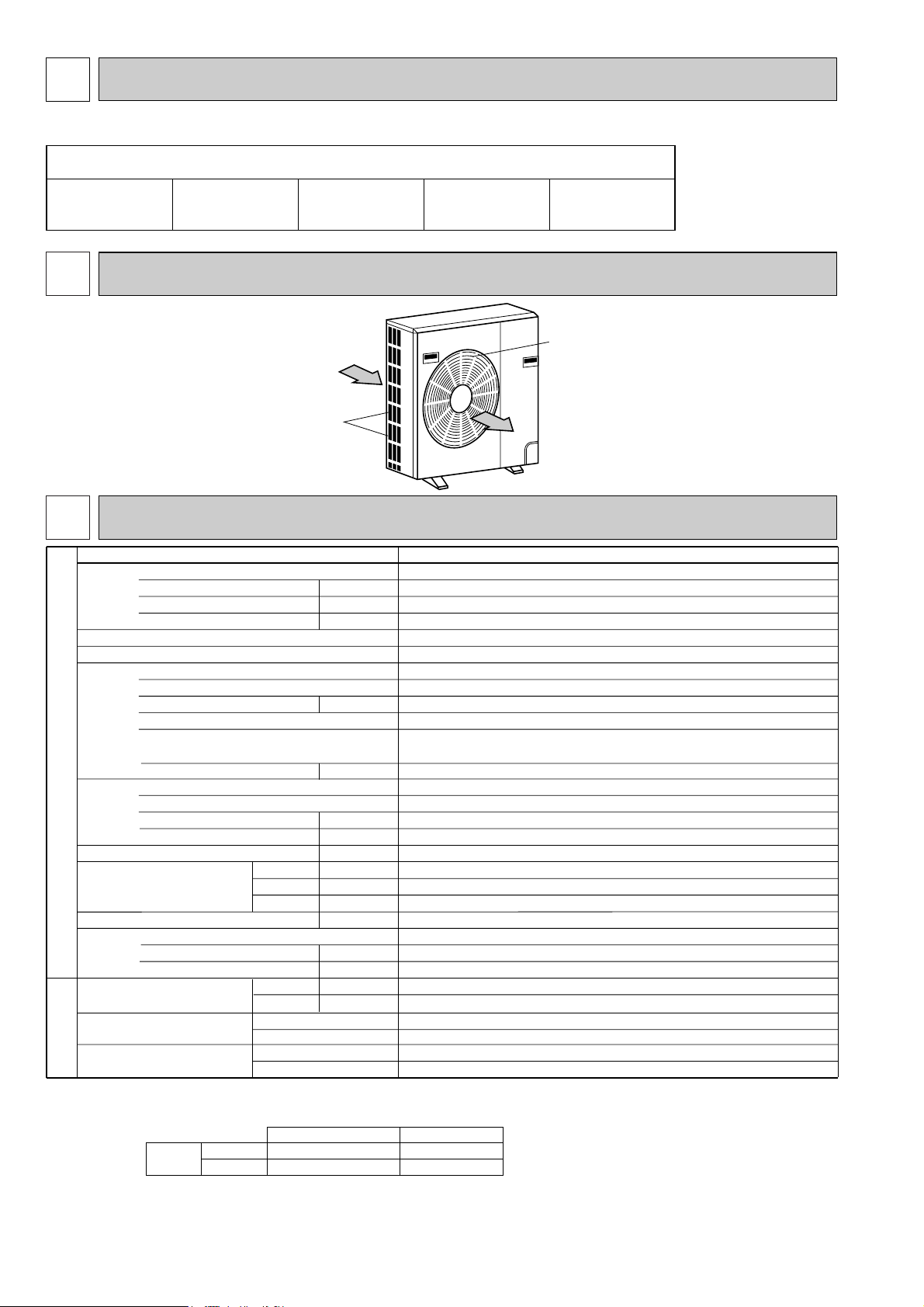
2 PART NAMES AND FUNCTIONS
1 COMBINATION OF INDOOR AND OUTDOOR UNITS
●Outdoor Unit
Air intake
Air outlet
(INDOOR UNIT)
Service Ref.
Power supply (phase, cycle, voltage)
External finish
Refrigerant control
Compressor
Heat exchanger
Noise level
Dimensions
Weight
Refrigerant
Pipe size O.D.
Connection method
Between the indoor & outdoor unit
Input
Running current
Starting current
Model
Motor output
Starter type
Protection devices
Cranckcase heater
Fan(drive) × No.
Fan motor output
Airflow
Charge
Oil (Model)
W
D
H
Liquid
Gas
Indoor side
Outdoor side
Height difference
Piping length
OUTDOOR UNIT
REFRIGERANT
PIPING
kW
A
A
kW
W
kW
CMM
dB
mm(in.)
mm(in.)
mm(in.)
kg(lbs)
kg(lbs)
L
mm(in.)
mm(in.)
3.18
15.1 / 5.7
54 /34
PU-3VJC.UK / PU-3YJC.UK
Single, 50Hz, 220~240V / 3, 50Hz, 380-415V (4wires)
Munsell 5Y 7/1
Capillary tube
Hermetic
NH52VNDT / NH52YDAT
2.2 / 2.4
Line start
/
32
Plate fin coil
Propeller (direct)
0.085
50
52
870(34-1/4)
295+24 (11-5/8 +1)
850(33-7/16)
73(161)
R-22
2.8(6.2)
1.6 (MS32)
9.52 (3/8)
15.88(5/8)
Flared
Flared
Max. 20m
Max. 30m
Notes1.Rating Conditions (JIS B8616)
Cooling: Indoor : D.B. 27°C(80°F), D.B. 19°C(66°F) Outdoor : D.B. 35°C(95°F), W.B. 24°C(75°F)
Refigerant piping length (one way) :5m (16ft)
2. Guaranteed operating range
3. Above values are as follows.
Indoor Unit 1 phase 220V 50Hz
Outdoor Unit 1 phase 220V 50Hz / 3 phase 380V 50Hz
Indoor
D.B. 35°C, W.B. 22.5°C
D.B. 21°C, W.B. 15.5°C
Outdoor
D.B. 52°C
D.B. 21°C
Upper limit
Lower limit
Cooling
Internal thermostat,
HP switch , LP switch
thermal switch, reversed-phase protector,
HPswitch, LP switch, thermal relay
3 SPECIFICATIONS
INDOOR UNIT Service Ref.
PC-3GJA
2
PE-3EJA3.TH
PED-3EJA
1.UK
PK-3FLA
3
PL-3GJB2.UK PS-3GJA2
PU-3VJC.UK/PU-3YJC.UK
3
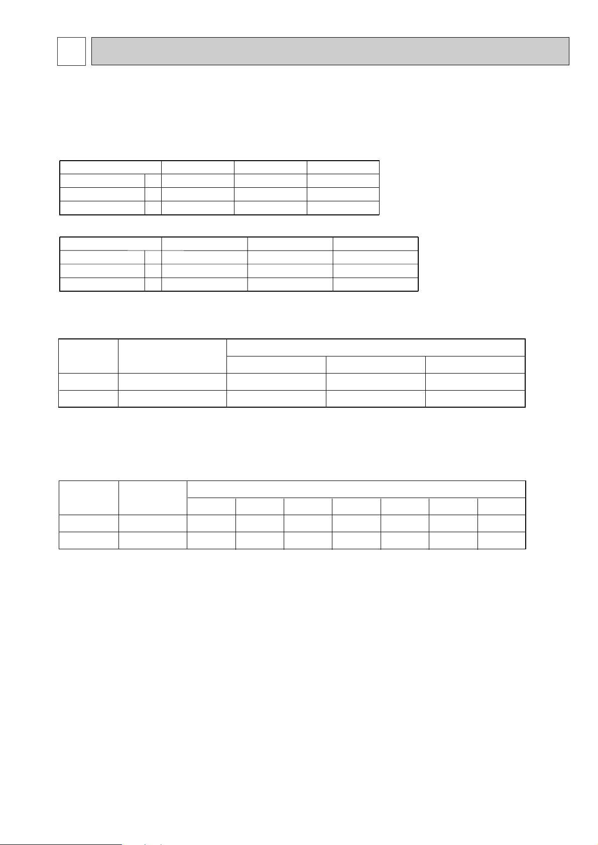
4 DATA
1. ELECTRICAL SPECIFICATIONS
Rating conditions
●JIS B 8616
Indoor : D.B. 27˚C(80˚F), W.B. 19˚C(66˚F)
Outdoor : D.B. 35˚C(95˚F), W.B. 24˚C(75˚F)
Power supply (1 phase)
Current
Input
Starting current
A
A
kW
Power supply (3 phase)
Current
Input
Starting current
A
A
kW
220V 50Hz
230V 50Hz
240V 50Hz
15.1
3.18
54
14.4
3.19
56
13.9
3.20
58
380/220V 50Hz
5.7
3.18
34
5.4
3.19
36
5.3
3.20
37
400/230V 50Hz 415/240V 50Hz
PU-3VJC.UK
PU-3YJC.UK
2. COMPRESSOR TECHNICAL DATA
Compressor
Winding resistance("). at 20:
R-C/U-V S-C/V-W W-U
NH52VNDT
NH52YDAT
0.83
3.68
2.03
3.68
—
3.68
PU-3VJC.UK
PU-3YJC.UK
Outdoor unit
Service Ref.
3. ADDITIONAL REFRIGERANT CHARGE (R-22
……
kg (lbs))
Outdoor unit
precharged (kg)
(up to 20m)
Refrigerant piping length (one way)
20m (66ft)
25m (82ft)
30m (98ft)
35m (115ft) 40m (131ft) 45m (148ft)50m (164ft)
2.8
2.8
0
0
0.06(0.13)
0.06(0.13)
0.12(0.26)
0.12(0.26)
—
—
—
—
—
—
—
—
PU-3VJC.UK
PU-3YJC.UK
Outdoor unit
Service Ref.
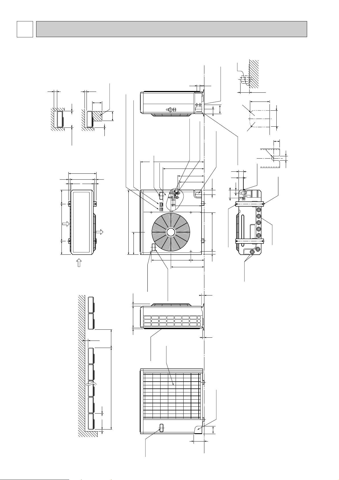
4
PU-3VJC.UK / PU-3YJC.UK
Unit : mm (inch)
100 10
1000For 10 units or less
200
Outdoor Unit-necessary surrounding clearance
(Concentrated installation)
The upper side must be open.
Outdoor Unit-necessary surrounding clearance
200
10
10
10
Note:Allow adequate
upper clearance
150
500
500
Service space
Front opening
Handle
for moving
138
95
Rear piping hole
23
33
Rear fresh
air intake
Side air intake
7 24(1)295(11-5/8)
Outlet guide
installation hole
302
Air intake
Air intake
Air outlet
870(34-1/4)
185
(7-9/32)
185
(7-9/32)
500(19-11/16)
330(13)
362(14-1/4)
1715
39.5 27.5
Terminal block for indoor and outdoor unit connection
Terminal block for power line with ground terminal
Handle for moving
179 524
441
337
352
403
553
850(33-7/16)
40 60524
Service panel
Refrigerant-pipe flared
connection [15.88 (5/8)
Refrigerant-pipe flared
connection [9.52 (3/8)
Knock out hole
for front piping
(refrigerant,drainage
and wiring)
Knock out hole
for front piping
(refrigerant,drainage
and wiring)
R
20
R
2
0
60
120
4553
25 max.
Knock out holes for
power line 2-[27
Standard bolt length
65
Front right piping holes-
detail figures
80
17
42
45
12
R6
104
33
Bottom
piping hole
2-U-shaped
notched
holes
Drain hole
Drain hole
2-12o23 Oval holes
(standard bolt M10)
Handle for moving
5 OUTLINES AND DIMENSIONS
 Loading...