


1999
SPLIT-TYPE AIR CONDITIONERS
No.OC187
TECHNICAL & SERVICE MANUAL
Outdoor unit |
|
[Model names] |
[Service Ref.] |
PU-3VJC
PU-3YJC
PU-3VJC PU-3YJC
CONTENTS
|
1. |
COMBINATION OF INDOOR AND OUTDOOR UNITS ····2 |
|
2. |
PART NAMES AND FUNCTIONS ···················2 |
|
3. |
SPECIFICATIONS ············································2 |
|
4. |
DATA ··················································· ·············3 |
|
5. |
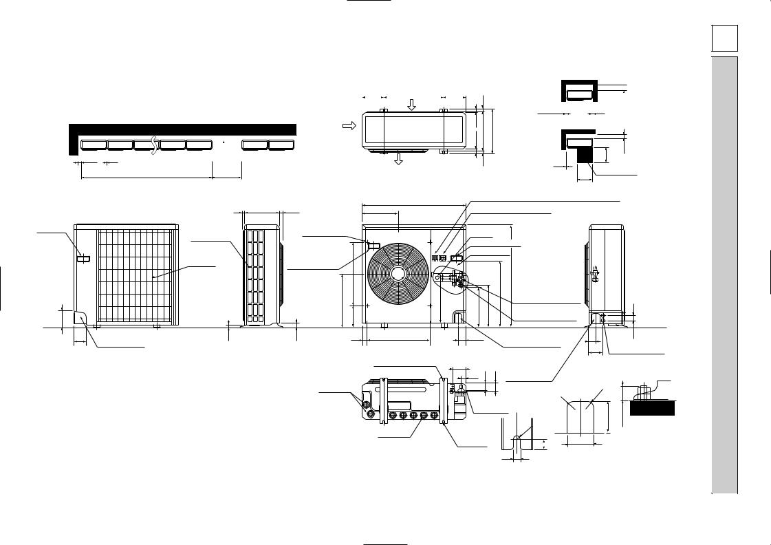
OUTLINES AND DIMENSIONS ·······················4 |
|
6. |
WIRING DIAGRAM ··········································5 |
Outdoor unit |
7. |
REFRIGERANT SYSTEM DIAGRAM··············5 |
8. DISASSEMBLY PROCEDURE ························6 |
||
|
9. |
PARTS LIST ··················································· ··8 |
|
10. OPTIONAL PARTS ·······································10 |
|

1 COMBINATION OF INDOOR AND OUTDOOR UNITS
(INDOOR UNIT)
INDOOR UNIT Service Ref.
PC-3GJA2 |
PE-3EJA3.TH |
PK-3FLA3 |
PL-3GJB2 |
PS-3GJA2 |
|
PED-3EJA1.UK |
PK-3FLA2.TH |
PL-3GJC1 |
PS-3GJ2 |
|
|
|
PL-3GJB2.UK |
|
|
|
|
|
|
2 PART NAMES AND FUNCTIONS
●Outdoor Unit
Air outlet
Air intake
3 SPECIFICATIONS
|
Service Ref. |
|
|
|
|
||||
|
Power supply (phase, cycle, voltage) |
|
|||||||
|
Input |
|
|
|
kW |
||||
|
Running current |
|
|
|
A |
||||
|
Starting current |
|
|
|
A |
||||
|
External finish |
|
|
|
|
||||
|
Refrigerant control |
|
|
|
|
||||
|
Compressor |
|
|
|
|
||||
|
Model |
|
|
|
|
||||
UNIT |
Motor output |
|
|
|
kW |
||||
Starter type |
|
|
|
|
|||||
OUTDOOR |
Heat exchanger |
|
|
|
|
||||
|
Protection devices |
|
|
|
|
||||
|
Cranckcase heater |
|
|
|
W |
||||
|
Fan(drive) / No. |
|
|
|
|
||||
|
Fan motor output |
|
|
|
kW |
||||
|
Airflow |
|
|
|
CMM |
||||
|
Noise level |
|
|
|
dB |
||||
|
|
|
|
|
|
|
W |
|
mm(in) |
|
Dimensions |
|
|
D |
|
mm(in) |
|||
|
|
|
|
|
|
|
H |
|
mm(in) |
|
Weight |
|
|
|
kg(lbs) |
||||
|
Refrigerant |
|
|
|
|
||||
|
Charge |
|
|
|
kg(lbs) |
||||
|
Oil (Model) |
|
|
|
l |
||||
REFRIGERANT PIPING |
Pipe size O.D. |
|
|
|
Liquid |
|
mm(in) |
||
|
|
|
|
||||||
|
|
|
Gas |
|
mm(in) |
||||
|
|
|
|
|
|||||
|
|
|
|
|
|
|
|
||
|
Connection method |
|
Indoor side |
|
|||||
|
|
Outdoor side |
|
||||||
|
|
|
|
|
|
||||
|
Between the indoor & outdoor unit |
|
Height difference |
||||||
|
|
Piping length |
|
||||||
|
|
|
|
|
|
||||
Notes1. Rating Conditions (JIS B8616) |
|
|
|
|
|||||
|
Cooling : Indoor :27°C(80°F)DB. 19°C(66°F)WB |
||||||||
|
Refigerant piping length (one way) :5m (16ft) |
|
|||||||
|
2. Guaranteed operating range |
|
Indoor |
||||||
|
|
||||||||
|
|
|
|
|
|
|
|||
|
|
Cooling |
Upper limit |
|
35°C DB, 22.5°C WB |
||||
|
|
Lower limit |
|
21°C DB, 15.5°C WB |
|||||
|
|
|
|
||||||
|
|
|
|
|
|
|
|
|
|
PU-3VJC / PU-3YJC
Single, 50Hz, 220~240V / 3, 50Hz, 380-415V (4wires)
3.18
15.1 / 5.7
54 /34 Munsell 5Y 7/1 Capillary tube Hermetic
NH52VND / NH52YDE 2.2 / 2.4
Line start
Internal thermostat, |
/ |
thermal switch, reversed-phase protector, |
|
HP switch , LP switch |
HPswitch, LP switch, thermal relay |
||
|
32 Plate fin coil
Propeller (direct) 0.085
50
52
870(34-1/4) 295+24 (11-5/8 +1) 850(33-7/16) 73(161)
R-22 2.8(6.2)
1.3(MS32)
9.52(3/8)
15.88(5/8) Flared Flared Max. 20m Max. 30m
Outdoor :35°C(95°F)DB. 24°C(75°F)WB
Outdoor
52°C DB
21°C DB
3. Above values are as follows. |
|
|
Indoor Unit |
1 phase 220V |
50Hz |
Outdoor Unit |
1 phase 220V |
50Hz / 3 phase 380V 50Hz |
2

4 DATA
1. ELECTRICAL SPECIFICATIONS
Rating conditions
Indoor : 27˚C(80˚F)D.B.,19˚C(66˚F)W.B. ●JIS B 8616 Outdoor : 35˚C(95˚F)D.B.,24˚C(75˚F)W.B.
PU-3VJC
Power supply (1 phase) |
220V 50Hz |
230V 50Hz |
240V 50Hz |
|
Current |
A |
15.1 |
14.4 |
13.9 |
|
|
|
|
|
Input |
kW |
3.18 |
3.19 |
3.20 |
|
|
|
|
|
Starting current |
A |
54 |
56 |
58 |
|
|
|
|
|
PU-3YJC
Power supply (3 phase) |
380/220V 50Hz |
400/230V 50Hz |
415/240V 50Hz |
|
Current |
A |
5.7 |
5.4 |
5.3 |
Input |
kW |
3.18 |
3.19 |
3.20 |
Starting current |
A |
34 |
36 |
37 |
|
|
|
|
|
2. COMPRESSOR TECHNICAL DATA
Outdoor unit |
Compressor |
|
Winding resistance("). |
at 20: |
|
Service Ref. |
R-C/U-V |
S-C/V-W |
W-U |
||
|
|||||
|
|
|
|
|
|
PU-3VJC |
NH52VND |
0.83 |
2.03 |
— |
|
PU-3YJC |
NH52YDE |
3.68 |
3.68 |
3.68 |
3. ADDITIONAL REFRIGERANT CHARGE (R-22……kg (lbs))
Outdoor unit |
Outdoor unit |
|
|
Refrigerant piping length (one way) |
|
|
|||
precharged (kg) |
|
|
|
|
|||||
|
|
|
|
|
|
|
|||
Service Ref. |
20m (66ft) |
25m (82ft) |
30m (98ft) |
35m (115ft) |
40m (131ft) |
45m (148ft) |
50m (164ft) |
||
(up to 20m) |
|||||||||
|
|
|
|
|
|
|
|
|
|
PU-3VJC |
2.8 |
0 |
0.06(0.13) |
0.12(0.26) |
— |
— |
— |
— |
|
|
|
|
|
|
|
|
|
|
|
PU-3YJC |
2.8 |
0 |
0.06(0.13) |
0.12(0.26) |
— |
— |
— |
— |
|
|
|
|
|
|
|
|
|
|
|
3
|
185 |
|
185 |
||
|
(7-9/32) |
500(19-11/16) |
(7-9/32) |
||
Outdoor Unit-necessary surrounding clearance |
|
|
|
|
|
(Concentrated installation) |
The upper side must be open. |
|
|
Air intake |
|
|
|
|
|||
|
|
|
|
|
|
|
|
Air intake |
100 |
10 |
200 |
Air outlet |
||
|
For 10 units or less |
1000 |
17 |
|
39.5 27.5 330(13) |
362(14-1/4) |
15 |
|
Outdoor Unit-necessary surrounding clearance
200
Note:Allow adequate 10 
 10 upper clearance
Front opening
500 |
150 |
10 |
|
Service space |
|
500 |
|
3YJC-PU / 3VJC-PU
870(34-1/4)
|
|
7 295(11-5/8) 24(1) |
302 |
|
|
|
|
Handle |
|
Outlet guide |
|
for moving |
|
|
|
|
installation hole |
|
|
|
Side air intake |
|
|
|
|
|
|
|
Rear fresh |
|
|
|
air intake |
Handle for moving |
|
|
|
|
|
4 |
|
|
524 |
|
|
|
|
|
|
441 |
403 |
138 |
|
|
179 |
Terminal block for indoor and outdoor unit connection Terminal block for power line
Ground terminal
Handle for moving Service panel
|
553 |
850(33-7/16) |
Refrigerant-pipe flared |
337 |
352 |
|
connection [15.88 5/8F |
|
Refrigerant-pipe flared |
||
|
|
|
connection [9.52 3/8F |
45
95 |
23 |
33 |
40 |
524 |
60 |
|
Knock out hole |
|
60 |
53 |
|
|
Rear piping hole |
|
|
|
|
|
|
for front piping |
|
120 |
Knock out holes for |
|
|
|
|
|
|
|
|
(refrigerant,drainage |
power line 2-[27 |
||
|
|
|
|
2-12o23 Oval holes |
|
|
|
and wiring) |
|
|
|
|
|
|
|
104 |
|
|
Knock out hole |
|
|
|
|
|
|
|
|
(standard bolt M10) |
|
|
|
|
|
||
|
|
|
|
33 |
42 |
45 |
|
|
|
||
|
|
|
|
|
for front piping |
|
|
|
|||
|
|
|
|
|
|
|
|
|
|
|
|
|
|
|
Drain hole |
|
|
|
|
(refrigerant,drainage |
0 |
|
|
|
|
|
|
|
|
|
|
and wiring) |
R |
2 |
|
|
|
|
|
|
Bottom |
|
20 |
R |
|
||
|
|
|
|
|
|
|
80 |
max.25 |
|||
|
|
|
|
|
piping hole |
|
|||||
Drain hole |
2-U-shaped |
R6 |
|
Unit |
holes |
17 |
65 |
||
|
notched |
|
|
|
|
|
|
Front right piping holes- |
: |
|
|
12 |
(inch) mm |
|
|
|
detail figures |
||
|
|
|
||
|
|
|
|
DIMENSIONS AND OUTLINES 5
 Loading...