


Mitsubishi PUH-1.6VKA3.UK, PUH-2NKA1.K, PUH-2VKA2.UK, PUH-2.5VKA2.UK, PUH-3VKA2.UK Service Manual
...
|
|
|
|
|
|
|
|
|
|
|
|
|
|
|
|
|
|
|
|
|
|
|
|
|
|
|
|
|
|
|
|
|
|
|
|
|
|
|
|
|
|
|
|
|
|
|
|
|
|
|
|
|
|
|
|
|
|
|
|
|
|
|
|
|
|
|
|
|
|
|
|
|
|
|
|
|
|
|
|
|
|
|
|
|
|
|
|
|
|
|
|
|
|
|
|
|
|
|
|
|
|
|
|
|
|
|
|
|
|
|
|
|
|
|
|
|
|
|
|
|
|
|
|
|
|
|
|
|
|
|
|
|
|
|
|
|
|
|
|
|
|
|
|
|
|
|
|
|
1997 |
|
|||||||||||||||||
|
|
|
|
|
|
|
|
|
|
|
|
|
|
|
|
|
|
|
|
|
|||||||||||||||||||||
|
|
|
|
|
|
|
|
|
|
|
|
|
|
|
|
|
|
|
|
|
|||||||||||||||||||||
|
|
|
|
|
|
|
|
|
|
|
|
|
|
|
|
|
|
|
|
|
|||||||||||||||||||||
|
|
|
|
|
|
|
|
|
|
|
|
|
|
|
|
|
|
|
|
|
|||||||||||||||||||||
|
|
|
|
|
|
|
|
|
|
|
|
|
|
|
|
|
|
|
|
|
|||||||||||||||||||||
|
|
|
|
|
|
|
|
|
|
|
|
|
|
|
|
|
|
|
|
||||||||||||||||||||||
|
|
|
|
|
|
|
|
|
|
|
|
|
|
|
|
|
|
|
|
||||||||||||||||||||||
|
|
|
|
|
|
|
|
|
|
|
|
|
|
|
|
|
|
|
|
||||||||||||||||||||||
SPLIT-TYPE, HEAT PUMP AIR CONDITIONERS |
|||||||||||||||||||||||||||||||||||||||||
|
|
|
|
|
|
|
|
|
|
|
|
|
|
|
|
|
|
|
|
|
|||||||||||||||||||||
|
|
|
|
|
|
|
|
|
|
|
|
|
|
|
|
|
|
|
|
|
|
|
|
|
|
|
|
|
|
|
|
|
|
|
|
|
|
|
|
|
|
|
|
|
|
|
|
|
|
|
|
|
|
|
|
|
|
|
|
|
|
|
|
|
|
|
|
|
|
|
|
|
|
No.OC150 |
|||||||||
|
|
|
|
|
|
|
|
|
|
|
|
|
|
|
|
|
|
|
|
|
|
|
|
|
|
|
|
|
|
REVISED EDITION-A |
|||||||||||
TECHNICAL & SERVICE MANUAL
Outdoor unit |
|
[Model names] |
[Service Ref.] |
PUH-1.6VKA |
PUH-1.6VKA3.UK |
||||
PUH-2VKA,2NKA |
PUH-2VKA2.UK,PUH-2NKA1.UK |
||||
PUH-2.5VKA,2.5NKA |
PUH-2.5VKA |
2 |
.UK,PUH-2.5NKA .UK |
||
|
|
|
1 |
||
PUH-3VKA,3NKA |
PUH-3VKA2.UK,PUH-3NKA1.UK |
||||
PUH-3YKA |
PUH-3YKA2.UK |
||||
PUH-4YKSA,4TKSA |
PUH-4YKSA |
2 |
.UK,4TKSA .UK |
||
|
|
|
1 |
||
PUH-5YKSA |
PUH-5YKSA2.UK |
||||
PUH-6YKSA |
PUH-6YKSA2.UK |
||||
CONTENTS
1. COMBINATION OF INDOOR AND OUTDOOR UNITS ·····2
2. PART NAMES AND FUNCTIONS·····················3
3. DATA··················································· ···············4
4. OUTLINES AND DIMENSIONS ························5
5. WIRING DIAGRAM ···········································9
6. REFRIGERANT SYSTEM DIAGRAM················17
7. DISASSEMBLY PROCEDURE ·······················19
8. PARTS LIST ··················································· ·21
9. OPTIONAL PARTS ························Back Cover
OUTDOOR UNIT
Revision:
●Parts List has been partially modified.
(Marking W in the PARTS LIST has been changed the PARTS LIST in OC150.)
●Please discard OC150.
The Slim Line.
From Mitsubishi Electric.
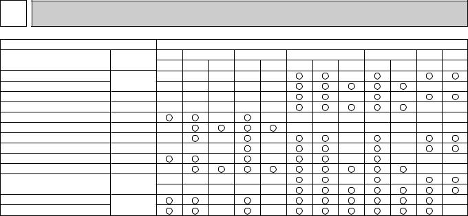
1 COMBINATION OF INDOOR AND OUTDOOR UNITS
Indoor unit |
|
|
|
|
|
|
Outdoor unit |
|
|
|
|
|
||
Service Ref. |
Service |
1.6 |
2 |
|
2.5 |
|
|
3 |
|
4 |
|
5 |
6 |
|
Manual No. VKA,VKA3.UK VKA2.UK |
NKA1.UK |
VKA2.UK NKA1.UK |
VKA2.UK |
YKA2.UK |
NKA1.UK YKSA2.UK TKSA1.UK YKSA2.UK YKSA2.UK |
|||||||||
|
||||||||||||||
PLH-GKH(S)B1·UK |
OC148 |
— |
— |
— |
— |
— |
|
|
— |
|
— |
|
|
|
PLH-GK(S)B1·UK |
— |
— |
— |
— |
— |
|
|
|
|
|
— |
— |
||
|
|
|
|
|
|
|||||||||
PLH-GKH(S)B1 |
OC139 |
— |
— |
— |
— |
— |
|
|
— |
|
— |
|
|
|
PLH-GK(S)B1 |
OC107 |
— |
— |
— |
— |
— |
|
|
|
|
|
— |
— |
|
PLH-KKHB·UK |
OC147 |
|
|
— |
|
— |
— |
— |
— |
— |
— |
— |
— |
|
PLH-KKB·UK |
OC119 |
— |
|
|
|
|
— |
— |
— |
— |
— |
— |
— |
|
PCH-GKH(S)A1 |
OC135 |
— |
|
— |
|
— |
|
|
— |
|
— |
|
|
|
PCH-GK(S)A1 |
OC136 |
— |
— |
— |
|
— |
|
|
— |
|
— |
|
|
|
PKH-1.6/2FKHA3, 2.5/3/4FKH(S)A2 |
OC130 |
|
|
— |
|
— |
|
|
— |
|
— |
— |
— |
|
PKH-2FKA3, 2.5/3/4FK(S)A2 |
OC132 |
— |
|
|
|
|
|
|
|
|
|
— |
— |
|
PSH-GJH(S)A1 |
OC142 |
— |
— |
— |
— |
— |
|
|
— |
|
— |
|
|
|
— |
— |
— |
— |
— |
|
|
|
|
|
|
|
|||
PEHD-EKH(S)A·UK |
|
|
|
|
|
|
|
|
||||||
— |
|
|
— |
|
— |
|
|
|
|
|
|
— |
||
PEHD-EK(S)A·UK |
|
|
— |
|
— |
|
|
|
|
|
|
— |
||
|
|
|
|
|
|
|
|
|
|
|||||
2
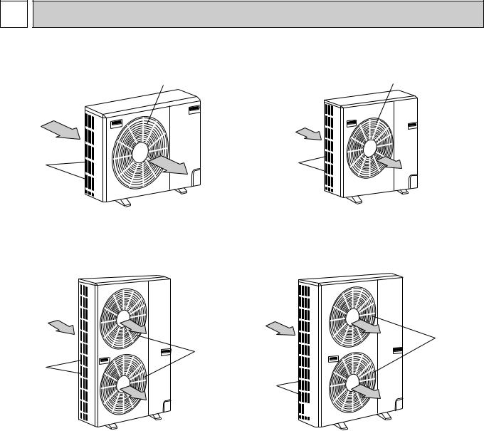
2 PART NAMES AND FUNCTIONS
Air outlet |
Air outlet |
(Expels warm air during cooling) |
Air intake |
Air intake |
PUH-1.6VKA3,2VKA2,2NKA1·UK PUH-2.5VKA2,2.5NKA1,3VKA2,3YKA2,3NKA1·UK
Air outlet
Air outlet
Air intake
Air intake
 PUH-5YKSA2·UK PUH-4YKSA2·UK 6YKSA2·UK
4TKSA1·UK
CHARGELESS SYSTEM
PRE-CHARGED REFRIGERANT IS SUPPLIED FOR UP TO 30m PIPING LENGTH AT SHIPMENT.
The unique refrigerant circuit and a large accumulator always control the optimal refrigerant level regardless of the length (50m max. and 5m min.) of piping. The additional refrigerant charging work during installation often causes problems. Therefore, it is completely eliminated. This unique system improves the quality and reliability of the work done. It also helps to speed up the installation work.
3
3 |
|
|
DATA |
|
|
|
|
|
|
|
|
|
|
|
|
|
|
|
|
|
|
|
|
|
|
|
|
|
|
||||
|
|
|
|
|
|
|
|
|
|
|
|
|
|
|
|
|
|
|
|
|
|
|
|
|
|
|
|
|
|
|
|
|
|
1. REFILLING REFRIGERANT CHARGE (R-22 : kg) |
|
|
|
|
|
|
|
|
|
|
|
|
|||||||||||||||||||||
|
|
|
|
|
|
|
|
|
|
|
|
|
|
|
|
|
|
|
|
|
|
|
|
|
|
|
|
|
|
|
|
|
|
Service Ref. |
|
|
|
|
|
|
|
|
|
|
|
Refrigerant piping length (one way) |
|
|
|
|
|
|
|
|
|||||||||||||
|
|
|
|
|
|
|
|
|
|
|
|
|
|
|
|
|
|
|
|
|
|
|
|
|
|
|
|
||||||
|
|
|
|
|
|
|
5m |
|
|
10m |
|
|
15m |
|
|
20m |
|
|
25m |
|
30m |
|
35m |
|
40m |
|
45m |
|
50m |
||||
|
|
|
|
|
|
|
|
|
|
|
|
|
|
|
|
|
|
|
|
|
|
|
|
|
|
|
|
|
|||||
PUH-1.6VKA3·UK |
|
1.5 |
|
|
1.7 |
|
|
1.8 |
|
|
1.9 |
|
|
2.1 |
|
2.2 |
|
2.3 |
|
|
2.4 |
|
— |
|
|
— |
|||||||
|
|
|
|
|
|
|
|
|
|
|
|
|
|
|
|
|
|
|
|
|
|
|
|
|
|
|
|
|
|
||||
PUH-2VKA2·UK |
|
1.5 |
|
|
1.7 |
|
|
1.8 |
|
|
1.9 |
|
|
2.1 |
|
2.2 |
|
2.3 |
|
|
2.4 |
|
— |
|
|
— |
|||||||
PUH-2NKA1·UK |
|
|
|
|
|
|
|
|
|
|
|
|
|
|
|
|
|||||||||||||||||
|
|
|
|
|
|
|
|
|
|
|
|
|
|
|
|
|
|
|
|
|
|
|
|
|
|
|
|
||||||
PUH-2.5VKA2·UK |
|
2.1 |
|
|
2.3 |
|
|
2.4 |
|
|
2.5 |
|
|
2.7 |
|
2.8 |
|
2.9 |
|
|
3.0 |
3.1 |
|
3.3 |
|||||||||
PUH-2.5NKA1·UK |
|
|
|
|
|
|
|
|
|
|
|
|
|
|
|||||||||||||||||||
|
|
|
|
|
|
|
|
|
|
|
|
|
|
|
|
|
|
|
|
|
|
|
|
|
|
|
|
||||||
PUH-3VKA2·UK |
|
2.5 |
|
|
2.7 |
|
|
2.8 |
|
|
2.9 |
|
|
3.1 |
|
3.2 |
|
3.3 |
|
|
3.4 |
3.6 |
|
3.7 |
|||||||||
PUH-3NKA1·UK |
|
|
|
|
|
|
|
|
|
|
|
|
|
|
|||||||||||||||||||
|
|
|
|
|
|
|
|
|
|
|
|
|
|
|
|
|
|
|
|
|
|
|
|
|
|
|
|
||||||
PUH-3YKA2·UK |
|
2.5 |
|
|
2.7 |
|
|
2.8 |
|
|
2.9 |
|
|
3.1 |
|
3.2 |
|
3.3 |
|
|
3.4 |
3.6 |
|
3.7 |
|||||||||
|
|
|
|
|
|
|
|
|
|
|
|
|
|
|
|
|
|
|
|
|
|
|
|
|
|
|
|
|
|
||||
PUH-4YKSA |
2 |
·UK |
|
3.5 |
|
|
3.6 |
|
|
3.8 |
|
|
3.9 |
|
|
4.1 |
|
4.2 |
|
4.4 |
|
|
4.5 |
4.6 |
|
4.8 |
|||||||
|
|
|
|
|
|
|
|
|
|
|
|
|
|
|
|
|
|
|
|
|
|
|
|
|
|
|
|
|
|
|
|
|
|
PUH-4TKSA1·UK |
|
4.0 |
|
|
4.1 |
|
|
4.3 |
|
|
4.4 |
|
|
4.6 |
|
4.7 |
|
4.9 |
|
|
5.0 |
5.1 |
|
5.3 |
|||||||||
PUH-5YKSA2·UK |
|
4.7 |
|
|
4.8 |
|
|
5.0 |
|
|
5.1 |
|
|
5.3 |
|
5.4 |
|
5.6 |
|
|
5.7 |
5.9 |
|
6.0 |
|||||||||
|
|
|
|
|
|
|
|
|
|
|
|
|
|
|
|
|
|
|
|
|
|
|
|
|
|
|
|
|
|||||
PUH-6YKSA2·UK |
|
4.3 |
|
|
4.4 |
|
|
4.6 |
|
|
4.7 |
|
|
4.9 |
|
5.0 |
|
5.2 |
|
|
5.3 |
5.5 |
|
5.6 |
|||||||||
|
|
|
|
|
|
|
|
|
|
|
|
|
|
|
|
|
|
|
|
|
|
|
|
|
|
||||||||
2. COMPRESSOR TECHNICAL DATA |
|
|
|
|
|
|
|
|
|
|
|
|
|
|
|
|
|
||||||||||||||||
|
|
|
|
|
|
|
|
|
|
|
|
|
|
|
|
|
|
|
|
||||||||||||||
|
Outdoor unit |
PUH-1.6 |
PUH-2 |
PUH-2 |
PUH-2.5 |
PUH-2.5 |
PUH-3 |
PUH-3 |
PUH-3 |
|
PUH-4 |
|
PUH-4 |
||||||||||||||||||||
|
|
|
3 |
|
2 |
·UK |
1 |
·UK |
2 |
·UK |
1 |
|
2 |
|
1 |
·UK |
2 |
|
2 |
·UK |
|
1 |
|||||||||||
|
|
|
|
|
|
|
VKA ·UK |
VKA |
NKA |
VKA |
NKA ·UK |
VKA ·UK |
NKA |
YKA ·UK |
|
YKSA |
|
TKSA ·UK |
|||||||||||||||
Compressor Model |
RH247VFC |
NH38VMD |
NHJ33NBD |
NH41VMD |
NHJ38NBD |
NH52VND |
NHJ47NAD |
NH52YDA |
|
NH56YDA |
|
NHJ56TKA |
|||||||||||||||||||||
|
|
|
|
|
|
|
|
|
|
|
|
|
|
|
|
|
|
|
|
|
|
|
|
|
|
|
|
|
|
|
|
|
|
Winding |
|
U-V |
|
2.00 |
|
1.05 |
|
0.70 |
|
1.03 |
|
0.70 |
|
0.83 |
|
0.58 |
|
3.60 |
|
3.50 |
|
0.83 |
|||||||||||
|
(R-C) |
|
|
|
|
|
|
|
|
|
|
||||||||||||||||||||||
Resistance |
|
U-W |
|
4.55 |
|
2.23 |
|
1.44 |
|
2.22 |
|
1.42 |
|
2.03 |
|
1.14 |
|
3.60 |
|
3.50 |
|
0.83 |
|||||||||||
|
(Ω ) |
|
(S-C) |
|
|
|
|
|
|
|
|
|
|
||||||||||||||||||||
|
|
|
|
|
|
|
|
|
|
|
|
|
|
|
|
|
|
|
|
|
|
|
|
|
|
|
|
|
|||||
|
|
|
|
|
|
|
|
|
|
|
|
|
|
|
|
|
|
|
|
|
|
|
|
|
|
|
|
|
|
|
|||
at 20˚C |
|
W-V |
|
— |
— |
|
|
— |
|
|
— |
|
|
— |
|
— |
— |
|
|
3.60 |
|
3.50 |
|
0.83 |
|||||||||
|
|
|
|
|
|
|
|
|
|
|
|
|
|
|
|
|
|
|
|
|
|
|
|
|
|
||||||||
|
|
|
|
|
|
|
|
|
|
|
|
|
|
|
|
|
|
|
|
|
|
||||||||||||
|
|
|
Outdoor unit |
|
|
|
|
|
|
|
PUH-5YKSA2·UK |
|
|
|
|
|
|
PUH-6YKSA2·UK |
|
|
|
||||||||||||
|
|
|
|
|
|
|
|
|
|
|
|
|
|
|
|
|
|
|
|
|
|||||||||||||
|
Compressor Model |
|
|
|
|
|
|
ZR61K3TFD |
|
|
|
|
|
|
|
|
ZR68KCTFD |
|
|
|
|||||||||||||
|
|
|
|
|
|
|
|
|
|
|
|
|
|
|
|
|
|
|
|
|
|
|
|
|
|
|
|
|
|||||
|
Winding |
|
|
T |
-T |
2 |
|
|
|
|
|
2.53-2.91 |
|
|
|
|
|
|
|
|
|
|
2.31 |
|
|
|
|
|
|||||
|
|
|
|
|
|
|
1 |
|
|
|
|
|
|
|
|
|
|
|
|
|
|
|
|
|
|
|
|
|
|
|
|
|
|
|
Resistance |
|
|
|
|
|
|
|
|
|
|
|
|
|
|
|
|
|
|
|
|
|
|
|
|
|
|
|
|
||||
|
|
T2-T3 |
|
|
|
|
|
2.53-2.91 |
|
|
|
|
|
|
|
|
|
|
2.31 |
|
|
|
|
|
|||||||||
|
|
|
(Ω ) |
|
|
|
|
|
|
|
|
|
|
|
|
|
|
|
|
|
|
|
|
|
|
|
|||||||
|
|
|
|
|
|
|
|
|
|
|
|
|
|
|
|
|
|
|
|
|
|
|
|
|
|
|
|
|
|
|
|
|
|
|
|
|
|
|
|
|
|
|
|
|
|
|
|
|
|
|
|
|
|
|
|
|
|
|
|
|
|
|
|
|
|
|
|
|
at 25˚C |
|
|
|
T3-T1 |
|
|
|
|
|
2.53-2.91 |
|
|
|
|
|
|
|
|
|
|
2.31 |
|
|
|
|
|
||||||
|
|
|
|
|
|
|
|
|
|
|
|
|
|
|
|
|
|
|
|
|
|
|
|
|
|
|
|
|
|
|
|
|
|
4
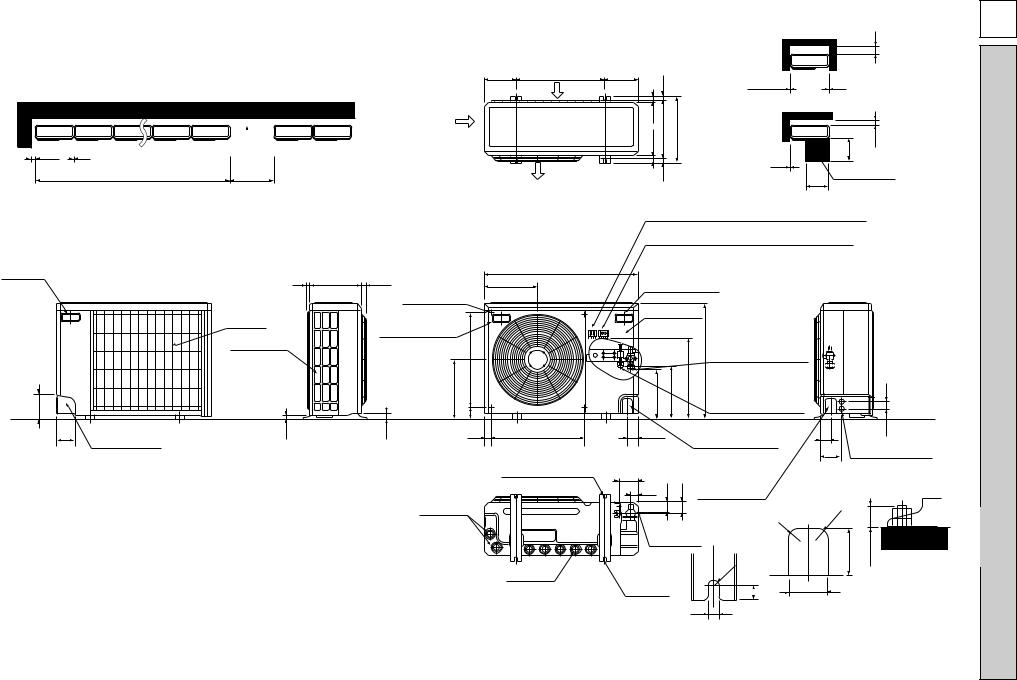
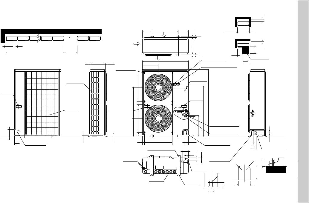
Outdoor Unit-Necessary surrounding clearance
(Concentrated installation) The upper side must be open.
|
|
200 |
Air intake |
100 |
10 |
|
|
|
|
||
|
For 10 units or less |
1000 |
|
Handle |
|
|
|
for moving |
|
7 295(11-5/8) 24(1) |
|
|
|
Outlet guide |
|
|
|
|
|
|
|
|
installation hole |
|
Rear fresh |
|
|
|
air intake |
Handle for moving |
|
|
|
||
|
Side air intake |
|
524 |
|
|
|
|
138 |
|
|
339 |
|
|
77 |
|
95 |
23 |
33 |
40 |
|
Rear piping hole |
|
|
Drain hole
5
185 (7-9/32) 500(19-11/16)
Air intake
Air outlet
870(34-1/4)
302
524
2-12o23 Oval holes (standard bolt M10)
Drain hole
|
17 |
|
|
|
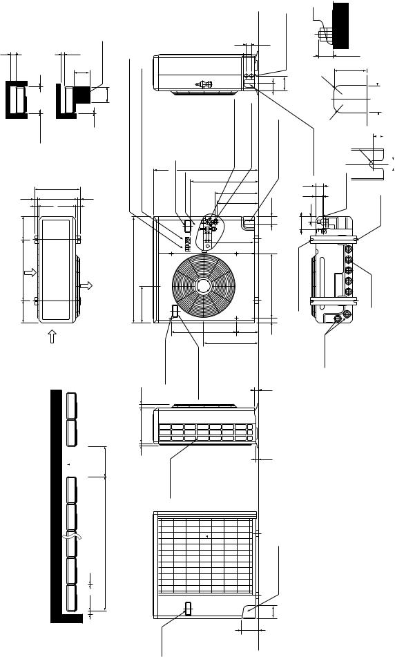
Outdoor Unit-Necessary surrounding clearance |
6VKA.1-PUH |
|||
|
|
|
|
|
|
||||
|
|
|
|
|
|
|
|
200 |
|
185 |
|
|
|
|
|
|
|
|
|
(7-9/32) |
|
|
|
|
|
|
Note:Allow adequate |
|
|
|
|
|
|
|
10 |
|
10 |
upper clearance |
|
39.5 27.5 |
15 330(13) |
362(14-1/4) |
|
|
Front opening |
|
2VKA-·UK,PUH3 |
||
|
|
10 |
500 |
100 |
|||||
|
|
|
|
|
|
|
|
|
|
|
|
|
|
|
|
|
Service space |
|
|
|
|
|
|
|
|
|
500 |
|
|
Terminal block for indoor and outdoor unit connection |
2 |
||||||||
|
|
|
|
5/8)-(25 |
[15.88 3/8F |
|
|
|
1·UK2NKA-·UK,PUH |
Terminal block for power line and Ground terminal |
|
|
|||||||
Handle for moving |
|
|
|
|
|||||
Service panel |
|
|
|
|
|
||||
|
|
|
|
|
Refrigerant-pipe flared |
|
|
|
|
|
|
|
|
|
connection |
|
|
|
|
282 |
297 |
444 |
650 |
[9.52 3/8F |
|
|
45 |
|
|
|
|
|
|
|
Refrigerant-pipe flared |
|
|
|
|
|
|
|
|
|
connection |
|
|
|
|
60 |
|
|
Knock out hole |
|
60 |
53 |
|
||
|
|
|
Knock out holes for |
|
|||||
|
|
for front piping |
|
|
|||||
|
|
|
|
|
120 |
|
|||
|
|
|
|
(refrigerant,drainage |
power line 2-[27 |
|
|||
|
|
|
|
and wiring) |
|
|
|
|
|
104 |
|
|
|
Knock out hole |
|
|
|
|
|
33 |
42 |
45 |
|
|
|
|
|||
for right piping |
|
|
|
|
|||||
|
|
|
|
|
|
|
|
||
|
|
|
|
(refrigerant,drainage |
R20 |
|
|
||
|
|
|
|
and wiring) |
R |
|
|
||
|
|
|
|
|
|
|
|||
Bottom |
|
|
20 |
|
|
|
|||
|
|
|
80 |
max.25 |
|
||||
piping hole |
|
|
|
||||||
|
|
|
|
|
|||||
2-U-shaped |
|
R6 |
|
|
Standard bolt length |
|
|||
|
|
|
|
|
|||||
notched |
|
|
|
|
|
65 |
|
||
|
|
|
|
|
|
|
|||
holes |
|
|
|
|
17 |
|
|
: Unit |
|
|
|
|
|
|
|
|
|||
|
|
|
|
12 |
Front right piping holes- |
||||
|
|
|
|
detail figures |
|
||||
|
|
|
|
|
|
||||
|
|
|
|
|
|
|
|
|
(inch) mm |
DIMENSIONS AND OUTLINES 4
|
|
|
|
|
PUH-2.5VKA ·UK,PUH-3VKA ·UK,PUH-3YKA |
2 |
·UK |
Unit : mm (inch) |
|
2 |
2 |
|
|
|
PUH-2.5NKA1·UK,PUH-3NKA1·UK
Necessary-UnitOutdoorsurrounding clearance |
Note:Allow adequate |
upper clearance |
openingFront |
|
10 |
Service space |
500 |
unitoutdoorandindoorconnection |
Groundandlinepowerterminal |
|
|
10 10 |
|
|
|
||||||||
200 |
|
|
|
100 |
|
|
|
|
|
|
|
|
|
|
|
|
500 |
|
|
|
|
|
|
|
|
|
5.27 |
5.39 |
|
|
|
Terminalblock for |
Terminalblock for |
Handlefor moving |
Servicepanel |
|
|
|
362(14 - 1/4) |
|
|
|
|
|
|
|
|
|
17 |
|
330(13) |
15 |
|
|
|
|
|
|
|
185 |
-9/32) |
|
|
|
|
|
|
|
|
|
|
|
(7 |
|
|
|
|
|
|
|
|
|
|
500(19-11/16) |
Air intake |
|
|
870(34-1/4) |
|
|
185 (7-9/32) |
|
Air outlet |
|
302 |
|
|
|
Air intake |
|
|
Outlet guide |
installation hole |
|
|
|
|
|
24(1) |
|
|
clearance |
be open. |
|
|
295(11-5/8) |
intakeairSide |
freshRear |
upperTheside must |
200 |
1000 |
7 |
|||
|
|
|
|
|
|
|
Outdoor Unit-Necessary surrounding |
(Concentrated installation) |
100 10 |
For 10 units or less |
|
|
|
6 |
|
|
|
Handle for moving |
|
|
|
|
|
|
|
|
|
45
-pipe flared |
[15.88 5/8F |
-pipe flared |
[9.52 3/8F |
Refrigerant |
connection |
Refrigerant |
connection |
850(33-7/16)
553 352
337
403
524 |
179 |
Handle for moving |
441 |
|
air intake
138
|
holes for |
2-[27 |
|
53 |
out |
line |
|
Knock |
power |
|
|
|
|
||
60 |
120 |
|
|
Knock out hole for front piping |
(refrigerant,drainage and wiring) |
Knock out hole for right piping |
|
|
|
|
45 |
60 |
|
|
42 |
|
|
33 |
|
|
|
|
104 |
524 |
|
2-12o23 Oval holes (standard bolt M10) |
|
40 |
|
|
|
33
23
Rear piping hole
95
|
|
25.max |
Standard bolt length |
|
|
|
|
||
|
R20 |
80 |
|
|
|
|
|
||
(refrigerant,drainage |
R |
20 |
|
|
|
|
|
||
wiring)and |
|
R6 |
||
|
|
Bottom piping hole |
2-U-shaped notched |
|
Drain hole
Drain hole
65 |
|
|
right piping holes- |
figures |
||
|
|
|||||
|
|
|
|
Front |
detail |
|
|
|
|
|
|||
|
|
|
|
|
|
|
|
|
|
|
|
|
|
17 |
|
|
|
|||
|
|
|
|
|
|
|
|
|
|
|
|
|
|
|
|
|
|
|
|
|
|
|
|
|
12 |
|
|
holes |
|
|
|
|||

Outdoor Unit-Necessary surrounding clearance |
Outdoor Unit-Necessary surrounding clearance |
|||
(Concentrated installation) |
300 |
|
|
|
|
|
|||
The upper side must be open. |
|
|
||
|
|
|
|
|
|
|
|
|
|
|
|
|
|
|
|
185 |
|
185 |
|
|
|
Note:Allow adequate |
|
|
|
|
|
|
(7-9/32) |
500(19-11/16) |
(7-9/32) |
|
|
|
|
|
|
|
|
|
|
17 |
10 |
10 |
upper clearance |
|||
|
|
|
|
|
|
|
Air intake |
|
||||
|
|
|
|
|
|
|
|
|
Front opening |
|
||
|
|
|
|
|
|
|
|
|
|
|
||
|
|
|
|
|
|
|
|
39.527.5 |
330(13) |
362(14-1/4) |
100 |
|
|
For 10 units or less |
1000 |
|
|
|
|
|
500 |
||||
150 |
10 |
300 |
|
|
|
|
|
|
|
|
|
|
|
|
|
Air intake |
|
|
|
|
|
|
|
||
|
|
|
|
|
|
|
|
|
|
|
|
|
|
|
|
|
|
|
|
|
|
|
Terminal block for |
10 |
|
|
|
|
|
|
|
|
|
|
|
indoor and outdoor |
|
|
|
|
|
|
|
|
Air outlet |
|
|
|
Service space |
||
|
|
|
|
|
|
|
|
15 |
unit connection |
|||
|
|
|
|
|
|
870(34-1/4) |
|
500 |
|
|||
|
|
7 |
295(11-5/8) |
24(1) |
|
|
|
|
|
|||
|
|
|
302 |
|
|
|
Terminal block for power line |
|
||||
|
|
|
|
|
Outlet guide |
|
|
|
|
|||
|
|
|
|
|
|
|
|
|
and Ground terminal |
|
|
|
|
|
|
|
|
installation hole |
|
|
|
|
|
|
|
|
Side air intake |
|
|
Service panel |
|
||
|
|
|
|
|
|
|
|
Handle |
|
|
524 |
|
|
|
|
|
|
|
|
|
|
|
|
for moving |
|
|
|
Handle |
|
|
|
|
|
585 |
|
1/2)- |
|
||
|
|
|
for moving |
|
|||
|
|
|
|
1258(49 |
|
||
|
Rear fresh |
|
61 |
|
959 |
|
|
|
|
|
|
|
|
|
|
|
air intake |
Handle for moving |
|
|
|
|
|
|
|
|
|
|
|
|
|
|
|
|
524 |
|
|
Refrigerant-pipe flared |
|
|
|
|
|
|
|
|
|
|
|
345 |
|
382 |
403 |
connection [19.05 3/4F |
45 |
138 |
|
83 |
Refrigerant-pipe flared |
||||
|
|
|
|
connection [9.52 3/8F |
|
||
|
|
|
|
|
|
|
|
95
Rear piping hole
23 |
33 |
40 524
2-12o23 Oval holes (standard bolt M10)
Drain hole
Drain hole
60 |
|
Knock out hole |
||
|
for front piping |
|||
|
|
|
||
104 |
|
|
(refrigerant,drainage |
|
|
|
and wiring) |
||
39 |
52 |
57 |
||
Knock out hole |
||||
|
|
|
||
|
|
|
for right piping |
|
Bottom
(refrigerant,
piping hole
drainage and wiring)
2-U-shaped |
R6 |
|
|
||
notched |
17 |
|
holes |
||
|
60 |
53 |
|
Knock out holes for |
||
120 |
||
power line 2-[27 |
R |
R20 |
20 |
|
80 |
25 max. |
|
|
Standard bolt length
65
12 |
|
|
|
|
Front right piping holes- |
|
|
|
|
detail figures |
|
|
|
|
|
|
7
·UK14TKSA-·UK,PUH24YKSA-PUH
(inch) mm : Unit
8
Outdoor Unit-Necessary surrounding clearance (Concentrated installation)
The upper side must be open.
150 |
300 |
10 |
Air intake
For 10 units or less |
1000 |
7 345(13-9/16) 24(1)
Outlet guide installation hole
|
Side air intake |
|
|
Handle |
|
|
524 |
|
|
|
|
for moving |
|
|
|
|
Rear fresh |
585 |
61 |
|
|
|
|
|
air intake |
Handle for moving |
|
|
|
|
|
|
|
345 |
524 |
|
|
|
|
138 |
|
|
83 |
95 |
23 |
33 |
90 |
|
Rear piping hole |
|
|
|
|
Drain hole |
|
|
|
|
|
|
|
|
Outdoor Unit-Necessary surrounding clearance |
|||
|
|
|
|
|
|
|
|
|
|
300 |
185 |
|
|
185 |
|
|
|
|
|
|
Note:Allow adequate |
(7-9/32) |
600(23-5/8) |
(7-9/32) |
|
|
|
|
|
|
||
17 |
|
|
10 |
|
10 |
upper clearance |
||||
|
Air intake |
|
|
|
|
|
||||
|
|
|
|
|
|
Front opening |
|
|||
|
|
|
|
|
|
|
|
|||
|
|
|
|
|
|
|
|
|
||
|
|
|
39.5 27.5 |
380(14-31/32) |
|
412(16-1/4) |
|
|
500 |
150 |
|
|
|
|
|
|
Terminal block for |
10 |
|
|
|
|
|
|
|
|
|
indoor and outdoor |
|
|
||
Air outlet |
|
|
|
|
|
|
Service space |
|||
|
|
|
15 |
|
unit connection |
|
||||
970(38-3/16) |
|
|
|
500 |
|
|||||
|
|
|
Terminal block for power line |
|
||||||
352 |
|
|
|
|
|
|
|
|||
|
|
|
|
|
and Ground terminal |
|
|
|
||
|
|
|
|
|
|
|
|
|
||
|
|
|
Service panel |
|
|
|
||||
|
|
|
Handle |
1/2) |
|
|
|
|||
|
|
|
for moving |
|
|
|
||||
|
|
|
|
|
|
959 |
1258(49- |
|
|
|
|
|
|
|
|
|
|
Refrigerant-pipe flared |
|
|
|
|
|
|
382 |
403 |
connection [19.05 3/4F |
|
45 |
|||
|
|
|
Refrigerant-pipe flared |
|
||||||
|
|
|
|
|
|
|
connection [9.52 3/8F |
|
|
|
|
524 |
|
60 |
|
|
Knock out hole |
|
60 |
53 |
|
|
|
|
|
|
Knock out holes for |
|||||
|
|
|
|
for front piping |
|
|||||
|
|
|
|
|
|
|
|
120 |
||
2-12o23 Oval holes |
|
104 |
|
|
|
(refrigerant,drainage |
|
power line 2-[27 |
||
|
|
|
|
|
|
|
||||
|
|
|
|
and wiring) |
|
|
|
|||
(standard bolt M10) |
|
|
|
|
|
|
|
|||
|
39 |
52 |
57 |
|
|
|
||||
|
|
|
|
|
||||||
|
|
|
Knock out hole |
|
|
|
||||
|
|
|
|
|
|
|
|
|
|
|
Bottom piping hole
2-U-shaped Drain hole notched
holes
for right piping
(refrigerant, |
R |
20 |
|
drainage and wiring) |
|
R6 17
65
R20
80 |
25 max. |
|
|
Standard bolt length
12 |
|
|
|
|
Front right piping holes- |
|
|
|
|
detail figures |
|
|
|
|
|
|
·UK26YKSA-·UK,PUH25YKSA-PUH
(inch) mm : Unit
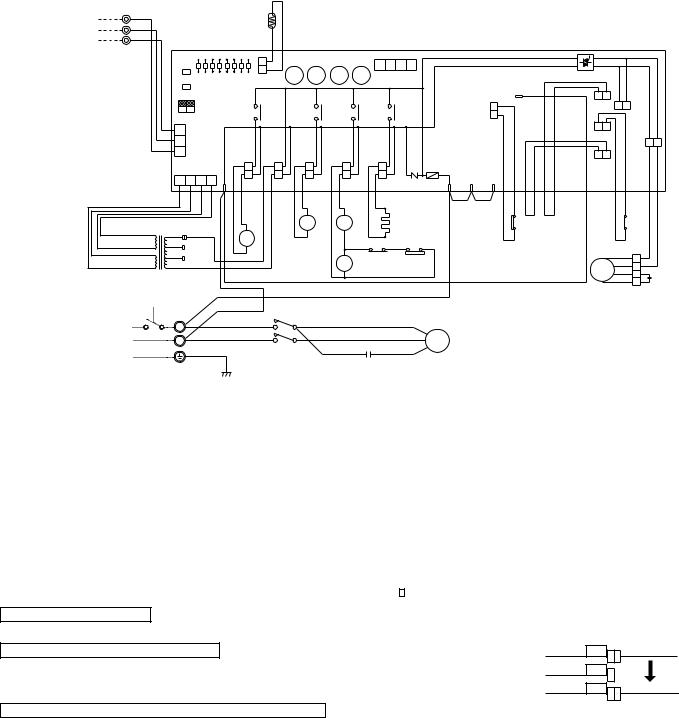
5 |
|
|
WIRING DIAGRAM |
|
|
|
|
|
|
|
|
|
|
|
|
PUH-1.6VKA ·UK |
|
|
|
|
|||
|
|
|
3 |
|
|
|
|
SYMBOL |
NAME |
SYMBOL |
NAME |
SYMBOL |
NAME |
||
HC |
CRANKCASE HEATER |
MC |
COMPRESSOR MOTOR(INNER THERMOSTAT) |
X12<O.B> |
COMPRESSOR RELAY |
||
C1 |
FAN MOTOR CAPACITOR |
MF |
FAN MOTOR (INDOOR THERMOSTAT) |
X13<O.B> |
21S4 RELAY |
||
C2 |
COMPRESSOR CAPACITOR |
O.B |
OUTDOOR CONTROLLER BOARD |
X14<O.B> |
21R RELAY |
||
FC<O.B> |
FAN CONTROLLER |
SW1·2·3<O.B> |
SELECT SWITCH(CHECK,SERVICE) |
X16 |
HIGH PRESSURE RELAY |
||
F<O.B> |
FUSE(6A) |
T |
TRANSFORMER |
ZNR<O.B> |
VARISTOR |
||
21S4 |
4-WAY VALVE SOLENOID COIL |
TB1,3 |
TERMINAL BLOCK |
52C |
COMPRESSOR CONTACTOR |
||
21R |
BYPASS VALVE SOLENOID COIL |
RT |
OUTDOOR COIL THERMISTOR |
63H1 |
HIGH PRESSURE SWITCH |
||
(0˚C/15kΩ ,25˚C/5.4kΩ ) |
|||||||
LD1~LD8 |
LED(CHECK, SERVICE) |
X11<O.B> |
HC RELAY |
63H2 |
PROTECTIVE HIGH PRESSURE SWITCH |
||
TO INDOOR UNIT |
1 |
YLW |
|
|
|
|
|
|
|
RT |
|
|
|
|
|
|
|
|
|
|
|
|
|
|
|
|
|
|
|
|
|
|
|
|
2 |
ORN |
|
|
|
|
|
|
|
|
|
|
|
|
|
|
|
|
|
|
|
|
|
|
|
|
|
|
|
|
|
|
|
||
CONNECTING WIRES |
|
|
|
|
|
|
|
|
|
|
|
|
|
|
|
|
|
|
|
|
|
|
|
|
|
|
|
|
|
|
|
|
||
3 |
BRN |
|
|
|
|
|
|
|
|
|
|
|
|
|
|
|
|
|
|
|
|
|
|
|
|
|
|
|
|
|
|
|
|
|
DC 12V (polar) |
|
|
|
|
|
|
|
|
|
|
|
|
|
|
|
|
|
|
|
|
|
|
|
|
|
|
|
|
|
|
|
|
||
|
O.B |
|
|
|
|
|
|
|
|
|
|
|
|
|
|
|
|
|
|
|
|
|
|
|
|
|
|
|
|
|
|
|
|
|
|
TB3 |
|
|
|
|
|
|
|
|
|
|
|
|
|
|
|
|
|
|
|
|
|
|
|
|
|
|
|
|
|
|
|
|
|
|
|
|
|
|
|
|
|
|
|
|
|
|
|
|
|
|
|
|
|
|
|
|
|
|
|
|
|
|
|
|
|
|
|
|
|
|
SW1 |
|
|
|
|
|
|
|
|
|
|
|
4 |
3 |
2 |
1 |
|
|
|
|
|
|
|
|
|
|
|
|
|
|
|
|
|
|
|
SW2 |
LD1 LD2 |
LD3 |
LD4 |
LD5 |
LD6 LD7 |
LD8 |
CN2 |
X14 |
X13 |
X12 |
X11 |
CN4 |
|
|
|
|
|
|
|
|
|
|
|
FC |
|
|
|
|
|
|||
|
|
|
|
|
|
|
|
|
|
|
|
|
|
|
|
|
|
|
|
|
|
|
|
|
|
|
||||||||
|
|
|
|
|
|
|
|
|
|
|
|
|
|
|
|
|
|
|
5 |
|
|
|
|
|
|
|
|
|
||||||
|
|
SW3 |
|
|
|
|
|
|
|
|
|
|
|
|
|
|
|
|
|
|
|
|
|
|
|
|
|
|
|
|
|
|
||
|
|
|
|
|
|
|
|
|
|
|
|
|
|
|
|
|
|
|
|
|
|
|
|
|
|
|
|
|
|
|
|
|
||
|
|
|
|
OFF |
|
|
|
|
|
|
|
|
|
|
|
|
|
|
|
|
|
|
|
|
|
|
|
|
|
26C |
|
MF2 |
|
|
|
|
|
|
ON |
|
|
|
|
|
X14 |
|
X13 |
X12 |
|
X11 |
|
|
|
63H1 |
|
|
|
|
|
|
|
|
|
|
|||||
|
|
2 |
1 |
|
|
|
|
|
|
|
|
|
|
|
|
|
|
|
|
|
|
|
|
|
|
|
||||||||
|
|
|
|
|
|
|
|
|
|
|
|
|
|
|
|
|
|
|
|
|
|
|
|
|
|
|||||||||
|
|
3 |
|
|
|
|
|
|
|
|
|
|
|
|
|
|
|
|
|
|
|
|
|
|
|
|
|
|
|
63H2 |
|
MF1 |
|
|
|
|
2 |
CN3 |
|
|
|
|
|
|
|
|
|
|
|
|
|
|
|
|
|
|
|
|
|
|
|
|
|
|
|
||||
|
|
|
|
|
|
|
|
|
|
|
|
|
|
|
|
|
|
|
|
|
|
|
|
|
|
|
|
|
|
|
|
|||
|
|
1 |
|
|
|
|
|
|
|
|
|
|
|
|
|
|
|
|
|
|
|
|
|
|
|
|
|
|
|
|
|
|
|
|
|
|
|
CN4T |
|
|
|
|
|
|
|
|
|
|
|
|
|
|
|
F |
|
|
|
|
|
|
|
|
|
51CM |
|
|
|
|
|
|
|
|
|
4 |
|
|
|
|
|
|
|
|
|
|
|
|
|
|
|
|
|
|
|
|
|
|
|
|
|
|
|
|||
|
|
4 |
3 |
2 |
1 |
|
SV |
|
TRF |
|
21S4 |
52C |
CH |
|
ZNR |
R/1 |
S/2 |
T/3 |
|
|
|
|
|
|
|
|
|
|
|
|
||||
|
|
|
|
|
|
|
|
|
|
|
|
|
|
|
|
|
|
|
|
|
|
|
||||||||||||
|
|
|
|
|
|
|
RED |
RED |
|
WHT |
WHT |
BLU BLU |
|
GRY GRY |
WHT WHT |
|
|
|
|
|
BLU |
BLU |
BRN |
BRN |
YLW |
YLW |
YLW |
YLW |
BLU |
VLT |
VLT |
|
BLU |
WHT |
|
|
|
|
|
|
|
|
|
|
|
|
|
|
|
|
|
||||||||||||||||||
|
|
|
|
|
|
|
|
|
|
|
|
|
|
A1 |
|
|
|
|
|
|
|
|
|
|
|
|
|
|
|
|
1 |
|
|
|
|
|
|
|
|
|
|
|
|
|
|
|
|
21 |
|
|
|
HC |
|
|
|
|
|
|
|
63H1 |
|
|
|
|
|
|
|||
|
|
|
|
|
|
|
|
|
|
|
|
|
52C |
|
|
|
|
|
|
|
|
|
|
|
|
|
X16 |
|
|
|||||
|
|
|
|
|
|
|
|
|
|
|
|
|
S4 |
|
|
|
|
|
|
|
|
|
|
|
|
|
|
|
||||||
|
|
YLW |
240V |
|
|
|
|
|
|
|
|
A2 |
|
|
|
|
|
|
|
|
|
|
|
|
|
|
|
|
5 |
|
|
|||
|
|
|
|
|
|
|
|
|
|
|
|
|
|
|
|
|
|
|
|
|
|
|
|
|
|
|
|
|
||||||
|
|
|
|
|
21R |
|
|
|
|
|
|
|
|
|
|
|
|
|
|
|
|
|
|
|
|
|
|
|
|
|||||
BRN AC12.3V |
ORN |
230V |
|
|
|
|
|
|
|
GRY |
GRY |
|
|
|
|
|
|
|
|
|
|
|
|
|
|
|
|
|
||||||
|
|
|
|
|
|
|
|
|
|
|
|
|
|
|
|
|
|
|
|
|
|
|
|
|
|
|
|
|
||||||
RED |
AC12.3V |
RED |
220V |
|
|
|
|
|
|
|
|
|
7 |
6X16 |
2 |
|
63H2 |
|
|
|
|
|
|
|
|
|
|
|
|
BLU |
4 |
|
|
|
|
|
|
|
|
|
|
|
|
|
|
|
X16 |
|
|
|
|
|
|
|
|
|
|
|
|
|
|
|
|
WHT |
3 |
|
|
||
|
|
|
|
|
|
|
|
|
|
|
|
|
|
|
|
|
|
|
|
|
|
|
|
|
|
|
|
|
MF |
RED |
||||
|
|
T |
|
|
|
|
|
|
|
|
|
|
|
8 |
|
GRY |
|
|
|
|
|
|
|
|
|
|
|
|
RED |
|||||
|
|
|
|
|
|
|
|
|
|
|
|
|
|
|
|
|
|
|
|
|
|
|
|
|
|
|
|
|
|
ORN |
2 |
|
C1 |
|
|
|
|
|
|
|
|
|
RED |
|
|
|
|
|
|
|
|
|
|
|
|
|
|
|
|
|
|
|
|
|
|
1 |
ORN |
||
|
|
|
|
|
|
|
|
|
|
|
|
|
|
|
|
|
|
|
|
|
|
|
|
|
|
|
|
|
|
|
|
|
||
|
|
TB1 |
|
|
|
|
BLU |
|
52C |
|
|
|
|
|
|
|
|
|
|
|
|
|
|
|
|
|
|
|
|
|
|
|||
|
|
|
|
|
|
|
|
|
|
|
|
|
|
|
|
|
|
|
|
|
|
|
|
|
|
|
|
|
|
|
||||
|
|
|
|
|
|
|
|
|
|
|
|
|
|
|
|
|
|
|
|
|
|
|
|
|
|
|
|
|
|
|
|
|
||
POWER SUPPLY |
|
L |
|
|
|
|
RED |
L1/1 |
|
T1/2 |
BLU |
|
|
|
|
R |
|
|
|
|
|
|
|
|
|
|
|
|
|
|
|
|||
|
|
|
|
|
BLU |
|
|
|
|
|
WHT |
|
|
|
C |
|
|
|
|
|
|
|
|
|
|
|
|
|
|
|
||||
~(1PHASE) |
|
N |
|
|
|
|
|
|
|
|
|
|
|
|
|
MC |
|
|
|
|
|
|
|
|
|
|
|
|
|
|
||||
|
|
|
|
|
|
|
L3/5 |
|
T3/6 |
BLU |
|
RED |
|
|
|
|
|
|
|
|
|
|
|
|
|
|
|
|||||||
220—240V 50Hz |
|
|
|
|
|
|
|
|
|
|
S |
|
|
|
|
|
|
|
|
|
|
|
|
|
|
|
||||||||
|
|
|
|
|
|
|
|
|
|
|
|
|
|
C2 |
|
|
|
|
|
|
|
|
|
|
|
|
|
|
|
|
|
|
||
|
|
GRN/YLW |
|
|
|
|
|
|
|
|
|
|
|
|
|
|
|
|
|
|
|
|
|
|
|
|
|
|
|
|
|
|||
|
|
|
|
|
|
|
|
|
|
|
|
|
|
|
|
|
|
|
|
|
|
|
|
|
|
|
|
|
|
|
|
|||
Main functions of LED (when both Nos.1 and 2 of |
SW3 |
are ”OFF” ) |
|
|
How to use SW1 and 2 |
|||||||||
|
|
|
|
|
|
|
|
●Pressing |
|
|
|
erases the past check contents loaded on the |
||
|
|
( |
) |
|
( |
|
) |
SW1 |
|
|||||
LED No. |
Output display |
light |
|
|
|
Check display |
flash |
|
microcomputer. |
|||||
LD1 |
Compressor indoor command |
|
|
— |
|
|
||||||||
|
|
|
|
●The output display (light) remains lit during operation but |
||||||||||
LD2 |
Heating indoor command |
|
|
|
— |
|
|
|||||||
|
|
|
|
|
pressing |
|
SW2 |
|
displays the past check contents in flashing |
|||||
LD3 |
63H1 |
ON |
|
|
Pipe temp. sensor short/open |
mode. Pressing the switch again returns to output display |
||||||||
LD4 |
Compressor |
ON |
|
|
|
— |
|
|
(light). |
|||||
LD5 |
Outdoor fan |
ON |
|
|
|
— |
|
|
|
|
|
|
|
|
LD6 |
4-way valve |
ON |
|
|
26C functions |
|
|
|
|
|
|
|
|
|
LD7 |
Bypass valve |
ON |
|
|
RT overheat protecyion |
|
|
|
|
|
|
|
||
LD8 |
Crankcase heater |
ON |
|
|
Defective input |
|
|
|
|
|
|
|
|
|
NOTES : 1. |
If the operation of the protection device stops to function. then check the display flashes. |
|||||
2. |
Symblos used in wiring diagram above are. /:Terminal block |
|
|
|
:Connector |
:PC board insertion tab. |
|
|
|
||||
CAUTIONS FOR SERVICING
●Connect the lead wires according to the color indication of sticker on the compressor terminal.
CAUTIONS FOR POWER SUPPLY WIRING
●Since LD8 lights when normal power is furned ”ON”, check the power supply with the ON or OFF LD8. wSince the transformer (T) is connected with 240V power, if 220V or 230V power is used,
change the wiring connection in the following procedure.
CAUTION FOR INDOOR AND OUTDOOR CONNECTING WIRES
wWhen power supply is 220V
YELLOW 240V |
|
ORANGE 230V |
|
RED 220V |
WHITE |
●Since the indoor and outdoor connecting wires has polarity, make sure to connect the same terminal numbers (1,2,3) for indoor and outdoor units.
9
|
|
|
|
|
|
|
|
|
|
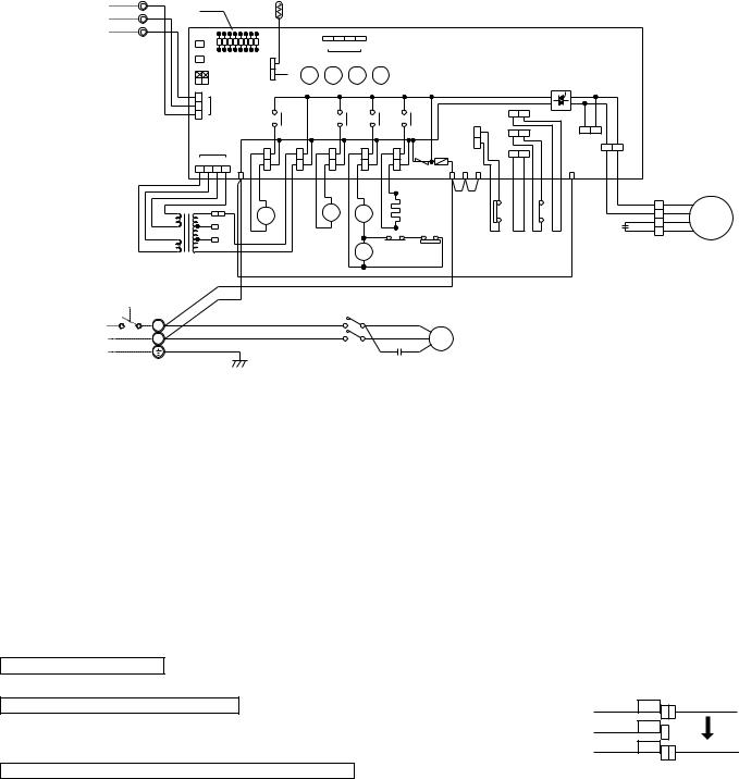
PUH-2VKA |
2 |
·UK,PUH-2.5VKA ·UK,PUH-3VKA |
2 |
·UK |
|
|
|||
|
|
2 |
|
|
|
|
|
||
|
|
|
|
|
|
|
|
|
|
SYMBOL |
|
|
NAME |
SYMBOL |
|
|
NAME |
SYMBOL |
NAME |
CN3(O.B) |
CONNECTOR (CONNECTING) |
MC |
COMPRESSOR |
X12(O.B) |
COMPRESSOR RELAY |
||||
|
WIRES INDOOR/OUTDOOR |
MF |
FAN MOTOR |
X13(O.B) |
SOLENOID COIL RELAY |
||||
CN4T(O.B) |
CONNECTOR(TRANSFORMER) |
O.B |
OUTDOOR CONTROLLER BOARD |
X14(O.B) |
SOLENOID COIL RELAY |
||||
HC |
CRANKCASE HEATER |
21R |
BYPASS VALVE SOLENOID COIL |
X16 |
HIGH PRESSURE RELAY |
||||
C1 |
FAN MOTOR CAPACITOR |
( ) |
SELECT SWITCH(CHECK,SERVICE) |
ZNR<O.B> |
SURGE ABSORBER |
||||
SW1·2·3O.B |
|||||||||
C2 |
RUN CAPACITOR FOR MC |
T |
TRANSFORMER |
21S4 |
4-WAY VALVE SOLENOID COIL |
||||
FC(O.B) |
FAN CONTROLLER |
TB1,3 |
TERMINAL BLOCK |
52C |
CONPRESSOR CONTACTOR |
||||
F(O.B) |
FUSE(6A) |
TH |
OUTDOOR COIL THERMISTOR |
63H1 |
CONTROL HIGH PRESSURE SWITCH |
||||
LD1-LD8(O.B) |
LED(CHECK,SERVICE) |
X11(O.B) |
CRANKCASE HEATER RELAY |
63H2 |
PROTECTIVE HIGH PRESSURE SWITCH |
||||
TO INDOOR UNIT CONNECTING WIRES DC 12V
POWER SUPPLY ~(1PHASE) 220—240V 50Hz
1 |
YLW |
|
LED |
|
|
|
|
|
|
|
|
|
|
|
|
|
|
|
|
|
|
|
|
|
|
|
|
|
||
2 |
|
|
TH |
|
|
|
|
|
|
|
|
|
|
|
|
|
|
|
|
|
|
|
|
|
|
|
|
|||
ORN |
|
|
|
|
|
|
|
|
|
|
|
|
|
|
|
|
|
|
|
|
|
|
|
|
|
|
|
|
||
O.B |
|
|
|
|
|
|
|
|
|
|
|
|
|
|
|
|
|
|
|
|
|
|
|
|
|
|
|
|
||
3 |
BRN |
|
|
|
|
|
|
|
|
|
|
|
|
|
|
|
|
|
|
|
|
|
|
|
|
|
|
|
|
|
|
|
|
|
|
|
|
|
|
|
|
|
|
|
|
|
|
|
|
|
|
|
|
|
|
|
|
|
|
||
TB3 |
SW1 |
|
|
|
|
|
4 3 |
2 |
1 |
|
|
|
|
|
|
|
|
|
|
|
|
|
|
|
|
|
|
|
||
SW2 |
|
|
|
|
|
|
|
|
|
|
|
|
|
|
|
|
|
|
|
|
|
|
|
|
||||||
|
|
LD1 LD2 LD3 LD4 LD5 LD6 LD7 LD8 |
|
|
CN4 |
|
|
|
|
|
|
|
|
|
|
|
|
|
|
|
|
|
|
|
|
|||||
|
|
|
|
|
|
|
|
|
|
|
|
|
|
|
|
|
|
|
|
|
|
|
|
|
|
|||||
|
|
SW3 |
|
|
|
|
|
|
|
|
|
|
|
|
|
|
|
|
|
|
|
|
|
|
|
|
||||
|
|
|
|
CN2 |
|
|
|
|
|
|
|
|
|
|
|
|
|
|
|
|
|
|
|
|
|
|
|
|
||
|
|
|
OFF |
X14 |
|
X13 |
X12 |
X11 |
|
|
|
|
|
|
|
|
|
|
|
|
|
|
|
|
|
|||||
|
|
|
ON |
|
|
|
|
|
|
|
|
|
|
|
|
|
|
|
|
|
|
|
|
|
|
|
|
|
||
|
|
2 1 |
|
|
|
|
|
|
|
|
|
|
|
|
|
|
|
|
|
|
|
|
|
|
|
|
|
|
|
|
|
|
|
3 |
|
|
|
|
|
|
|
|
|
|
|
|
|
|
|
|
|
|
|
|
|
|
|
|
|
|
|
|
|
|
2 |
CN3 |
|
|
|
|
|
|
|
|
|
|
|
|
|
|
26C |
|
|
|
|
|
|
|
|
|
||
|
|
|
1 |
|
|
|
X14 |
|
|
X13 |
|
X12 |
|
X11 |
|
|
|
|
|
|
|
F.C |
|
|
|
|
||||
|
|
|
|
|
|
|
|
|
|
|
|
|
|
|
|
|
|
|
|
|
|
|
|
|
|
|||||
|
|
|
|
|
|
|
|
|
|
|
|
|
|
|
|
|
63H1 |
|
63H2 |
|
|
|
|
MF2 |
|
|
|
|
||
|
|
|
|
|
|
|
|
|
|
|
|
|
|
|
|
|
|
|
|
|
|
|
|
|
|
|
||||
|
|
|
|
|
|
|
|
|
|
|
|
|
|
|
|
|
|
|
|
|
|
|
|
|
MF1 |
|
|
|
||
|
|
|
CN4T |
|
|
|
|
|
|
|
|
|
|
|
|
|
|
51CM |
|
|
|
|
|
|
|
|
||||
|
|
4 |
3 |
2 |
1 |
|
|
|
|
|
|
|
|
|
|
|
|
|
|
|
|
|
|
|
|
|
|
|
||
|
|
|
|
|
|
|
|
|
|
|
ZNR |
|
|
|
|
|
|
|
|
|
|
|
|
|
|
|
||||
|
|
|
|
|
4 |
SV |
TRF |
|
21S4 |
|
52C |
|
|
F R |
S |
T |
|
|
|
|
|
|
|
5 |
|
|
|
|
||
|
RED |
|
|
|
|
|
|
|
CH |
|
|
|
|
|
|
|
|
|
|
|
|
|
|
|
||||||
|
|
|
|
RED |
RED |
BLU |
BLU |
GRY |
GRY |
|
WHT |
WHT |
|
|
|
|
|
BRN |
BRN |
YLW |
YLW VLT |
VLT |
YLW |
YLW |
BLU |
|
|
|
|
|
|
RED |
|
|
|
|
|
|
|
BLU |
BLU |
|
|
|
|
||||||||||||||||
|
BRN |
|
|
|
|
|
|
|
|
|
|
|
||||||||||||||||||
|
|
|
|
|
|
|
|
|
|
|
A1 |
|
|
|
|
|
|
|
|
|
1 |
|
|
WHT |
|
WHT |
|
|||
|
|
|
|
|
|
|
|
|
|
|
|
|
|
|
|
|
|
|
|
|
|
|
|
|
|
|||||
|
BRN |
YLW |
|
|
|
|
21 |
|
|
|
|
|
|
|
|
|
|
|
|
|
|
|
3 |
|
||||||
|
|
|
|
|
|
|
|
|
|
|
HC |
|
|
|
|
|
63H1 |
|
|
X16 |
|
|
BLU |
BLU |
MF |
|||||
|
AC |
|
21R |
|
|
|
52C |
|
|
|
|
|
|
|
|
|
|
|
4 |
|||||||||||
|
ORN 240V |
|
|
S4 |
|
|
|
|
|
|
|
|
|
|
|
|
5 |
|
|
RED |
RED |
|||||||||
|
12.3V |
|
|
|
|
A2 |
|
|
|
|
|
|
|
|
|
|
|
|
C1 |
2 |
||||||||||
|
|
RED |
230V |
|
|
|
|
|
|
|
|
GRY |
|
|
|
|
|
|
|
|
|
|
ORN 1 |
ORN |
|
|||||
|
|
220V |
WHT |
|
|
|
|
|
GRY |
|
|
|
|
|
|
|
|
|
|
|
|
|
|
|
|
|
||||
|
AC12.3V |
|
|
|
|
|
|
|
|
7 |
6 X16 |
2 |
|
|
|
|
|
|
|
|
|
|
|
|
|
|
|
|||
|
|
|
|
|
WHT |
|
|
|
|
|
|
|
|
|
|
|
|
|
|
|
|
|
|
|
|
|||||
|
|
|
|
|
|
|
|
|
|
X16 |
|
|
63H2 |
|
|
|
|
|
|
|
|
|
|
|
|
|
|
|||
|
|
T |
|
|
|
|
|
|
|
|
|
|
|
|
|
|
|
|
|
|
|
|
|
|
|
|
|
|
||
|
|
|
|
|
|
|
|
|
|
|
8 |
|
GRY |
|
|
|
|
|
|
|
|
|
|
|
|
|
|
|
||
|
|
|
|
|
|
|
|
|
|
|
|
|
|
|
|
|
|
|
|
|
|
|
|
|
|
|
|
|||
|
|
|
|
|
|
RED |
|
|
|
|
|
|
|
|
|
|
|
|
|
|
|
|
|
|
|
|
|
|
|
|
|
|
|
|
|
BLU |
|
|
|
|
|
|
|
|
|
|
|
|
|
|
|
|
|
|
|
|
|
|
|
|
|
|
TB1 |
|
|
|
|
RED |
|
|
L1/1 |
|
T1/2 |
BLU |
|
R |
|
|
|
|
|
|
|
|
|
|
|
|
|
|
|
|
|
L |
|
|
|
|
|
|
|
|
|
|
|
|
|
|
|
|
|
|
|
|
|
|
|
||||||
|
|
|
|
|
|
|
|
|
|
|
|
|
|
|
|
|
|
|
|
|
|
|
|
|
|
|
|
|
|
|
|
N |
|
|
|
|
BLU |
|
|
|
|
|
|
WHT |
|
C |
MC |
|
|
|
|
|
|
|
|
|
|
|
|
|
|
|
|
|
|
|
|
|
|
L3/5 |
|
T2/6 |
BLU |
|
RED |
|
|
|
|
|
|
|
|
|
|
|
|
|
|
|||
|
|
|
|
|
|
|
|
|
|
|
|
|
|
|
|
|
|
|
|
|
|
|
|
|
|
|
||||
|
|
GRN/YLW |
|
|
|
|
|
52C |
|
|
|
S |
|
|
|
|
|
|
|
|
|
|
|
|
|
|
|
|||
|
|
|
|
|
|
|
|
|
|
|
|
|
|
C2 |
|
|
|
|
|
|
|
|
|
|
|
|
|
|
|
|
Main functions of LED (when both Nos.1 and 2 of |
SW3 |
are ”OFF” ) |
|
|
|
How to use SW1 and 2 |
|||||||
|
|
|
|
|
|
|
|
●Pressing |
|
|
|
erases the past check contents loaded on the |
|
|
|
( ) |
|
|
( |
|
) |
SW1 |
|
||||
LED No. |
Output display |
light |
|
Check display |
|
flash |
|
microcomputer. |
|||||
LD1 |
Compressor indoor command |
|
— |
|
|
|
|||||||
|
|
|
|
●The output display (light) remains lit during operation but |
|||||||||
LD2 |
Heating indoor command |
|
— |
|
|
|
|||||||
|
|
|
|
pressing |
|
SW2 |
|
displays the past check contents in flashing |
|||||
LD3 |
63H1 |
ON |
Pipe sensor short/open |
|
|
mode. Pressing the switch again returns to output display |
|||||||
LD4 |
Compressor |
ON |
|
— |
|
|
|
(light). |
|||||
LD5 |
Outdoor fan |
ON |
|
— |
|
|
|
|
|
|
|
|
|
LD6 |
4-way valve |
ON |
|
— |
|
|
|
|
|
|
|
|
|
LD7 |
Bypass valve |
ON |
TH overheat protecyion |
|
|
|
|
|
|
|
|||
LD8 |
Crankcase heater |
ON |
Defective input |
|
|
|
|
|
|
|
|
|
|
NOTE : If the operation of the protection device stops to function. then check the display flashes.
CAUTIONS FOR SERVICING
●Connect the lead wires according to the color indication of sticker on the compressor terminal.
CAUTIONS FOR POWER SUPPLY WIRING
●Since LD8 lights when normal power is furned ”ON”, check the power supply with the ON or OFF LD8. wSince the transformer (T) is connected with 240V power, if 220V or 230V power is used,
change the wiring connection in the following procedure.
CAUTION FOR INDOOR AND OUTDOOR CONNECTING WIRES
wWhen power supply is 220V
YELLOW 240V |
|
ORANGE 230V |
|
RED 220V |
WHITE |
●Since the indoor and outdoor connecting wires has polarity, make sure to connect the same terminal numbers (1,2,3) for indoor and outdoor units.
10
|
|
|
|
|
|
|
|
|
|
PUH-2NKA |
1 |
·UK,PUH-2.5NKA |
1 |
·UK,PUH-3NKA ·UK |
|
|
|||
|
|
|
|
|
1 |
|
|
||
|
|
|
|
|
|
|
|
|
|
SYMBOL |
|
|
NAME |
|
|
SYMBOL |
NAME |
SYMBOL |
NAME |
HC |
CRANKCASE HEATER |
|
|
O.B |
OUTDOOR CONTROLLER BOARD |
X14(O.B) |
SOLENOID COIL RELAY |
||
C1 |
FAN MOTOR CAPACITOR |
|
|
RT |
OUTDOOR COIL THERMISTOR |
ZNR(O.B) |
VARISTOR |
||
|
|
(0˚C/15kΩ ,25˚C/5.4kΩ ) |
|||||||
C2 |
COMPRESSOR CAPACITOR |
SW1·2·3(OB) |
SELECT SWITCH(CHECK,SERVICE) |
21S4 |
4-WAY VALVE SOLENOID COIL |
||||
FC<O.B> |
FAN CONTROLLER |
|
|
T |
TRANSFORMER |
21R |
BYPASS VALVE SOLENOID COIL |
||
F<O.B> |
FUSE(6A) |
|
|
TB1,3 |
TERMINAL BLOCK |
52C |
COMPRESSOR CONTACTOR |
||
LD1~LD8 |
LED(CHECK,SERVICE) |
|
|
X11(O.B) |
HC RELAY |
63H1 |
HIGH PRESSURE SWITCH |
||
MC |
COMPRESSOR MOTOR(INNER THERMOSTAT) |
|
X12(O.B) |
COMPRESSOR RELAY |
|
|
|||
MF |
FAN MOTOR(INNER THERMOSTAT) |
X13(O.B) |
SOLENOID COIL RELAY |
|
|
||||
1 |
YLW |
|
|
TO INDOOR UNIT |
|
|
|
2 |
ORN |
|
|
CONNECTING WIRES |
|
|
|
3 |
BRN |
|
|
DC 12V (polar) |
O.B |
|
|
TB3 |
|
|
|
|
|
|
|
|
SW1 |
|
|
|
SW2 |
LD1 LD2 LD3 LD4 LD5 LD6 LD7 LD8 |
|
|
|
|
|
|
SW3 |
|
|
|
|
|
OFF |
|
|
|
ON |
|
2 |
1 |
|
|
3 |
|
|
|
2 |
CN3 |
|
|
1 |
|
|
RT
|
|
4 |
3 |
2 |
1 |
|
|
CN2 |
X14 X13 X12 |
X11 |
CN4 |
|
FC |
|
|
|
|
|
|
|
|
5 |
|
|
|
|
|
|
63H1 |
26C |
|
X14 |
X13 |
X12 |
|
X11 |
|
MF2 |
|
|
|
|
|||||
|
|
|
|
|
|
63H2 |
MF1 |
|
|
|
|
|
|
|
|
|
|
CN4T |
|
4 |
|
|
|
|
|
|
|
|
|
|
F |
|
|
|
4 |
3 |
2 |
1 |
|
SV |
|
TRF |
|
21S4 |
|
52C |
|
CH |
ZNR R/1 S/2 |
T/3 |
|
|
|
|
|
|
|
|
|
|
|
|
|||||||
|
|
|
|
|
RED |
RED |
WHT |
WHT |
BLU |
BLU |
GRY |
GRY |
WHT |
WHT |
|
BLU |
BLU |
|
YLW |
|
|
|
|
|
|
|
|
|
|
|
A1 |
|
|
|
|
|
240V |
|
|
|
21R |
|
|
|
21 |
|
52C |
|
|
HC |
|
||
BRN AC12.3V |
ORN |
|
|
|
|
|
|
|
|
|
|
||||||
230V |
|
|
|
|
|
|
|
S4 |
|
A2 |
|
|
|
|
|||
|
RED |
220V |
|
|
|
|
|
|
|
|
|
|
|
|
|
||
|
|
|
|
|
|
|
|
|
|
|
|
|
|
|
|||
RED AC12.3V
|
51CM |
|
|
BRN BRN YLW YLW YLW YLW |
BLU |
|
BLU WHT |
63H1 |
|
|
|
|
BLU |
4 |
|
|
MF REDWHT |
3 |
RED |
|
ORN |
2 |
C1 |
|
|
1 |
ORN |
|
T |
RED |
|
|
|
|
|
|
|
|
|
|
|
|
|
|
|
|
TB1 |
BLU |
|
52C |
|
|
|
|
|
|
|
|
|
|
|
||
|
|
|
|
|
|
|
|
|
|
L |
RED |
L1/1 |
T1/2 |
BLU |
|
|
R |
POWER SUPPLY |
|
|
|
|
|
|
||
N |
BLU |
|
|
WHT |
|
C |
MC |
|
~(1PHASE) |
|
L3/5 |
T3/6 |
BLU |
RED |
|
||
|
|
|
S |
|||||
220V—60Hz |
|
|
|
|
|
|||
|
|
|
|
|
|
|
||
|
|
|
|
|
|
|
|
GRN/YLW |
C2 |
|
Main functions of LED (when both Nos.1 and 2 of |
SW3 |
are ”OFF” ) |
|
|
How to use SW1 and 2 |
||||||||||||
|
|
|
|
|
|
|
|
|
|
|
|
●Pressing |
|
|
|
erases the past check contents loaded on the |
|
|
|
( |
) |
|
|
|
|
|
|
( |
) |
SW1 |
|
||||
LED No. |
Output display |
light |
|
|
Check display |
flash |
|
microcomputer. |
|||||||||
LD1 |
Compressor indoor command |
|
|
— |
|
|
|||||||||||
|
|
|
|
●The output display (light) remains lit during operation but |
|||||||||||||
LD2 |
Heating indoor command |
|
|
|
— |
|
|
||||||||||
|
|
|
|
|
pressing |
|
SW2 |
|
displays the past check contents in flashing |
||||||||
LD3 |
63H1 |
ON |
|
Pipe temp. sensor short/open |
mode. Pressing the switch again returns to output display |
||||||||||||
LD4 |
Compressor |
ON |
|
|
|
— |
|
|
(light). |
||||||||
LD5 |
Outdoor fan |
ON |
|
|
|
— |
|
|
|
|
|
|
|
|
|||
LD6 |
4-way valve |
ON |
|
|
|
— |
|
|
|
|
|
|
|
|
|||
LD7 |
Bypass valve |
ON |
|
RT overheat protecyion |
|
|
|
|
|
|
|
||||||
LD8 |
Crankcase heater |
ON |
|
Defective input |
|
|
|
|
|
|
|
|
|||||
NOTES : 1. If the operation of the protection device stops to function. then check the display flashes. |
|||||||||||||||||
2. Symblos used in wiring diagram above are. /:Terminal block |
|
|
|
|
:Connector |
:PC board insertion tab. |
|||||||||||
|
|
|
|
||||||||||||||
CAUTIONS FOR SERVICING
●Connect the lead wires according to the color indication of sticker on the compressor terminal.
CAUTIONS FOR POWER SUPPLY WIRING
●Since LD8 lights when normal power is furned ”ON”, check the power supply with the ON or OFF LD8. wSince the transformer (T) is connected with 240V power, if 220V or 230V power is used,
change the wiring connection in the following procedure.
CAUTION FOR INDOOR AND OUTDOOR CONNECTING WIRES
●Since the indoor and outdoor connecting wires has polarity, make sure to connect the same terminal numbers (1,2,3) for indoor and outdoor units.
11
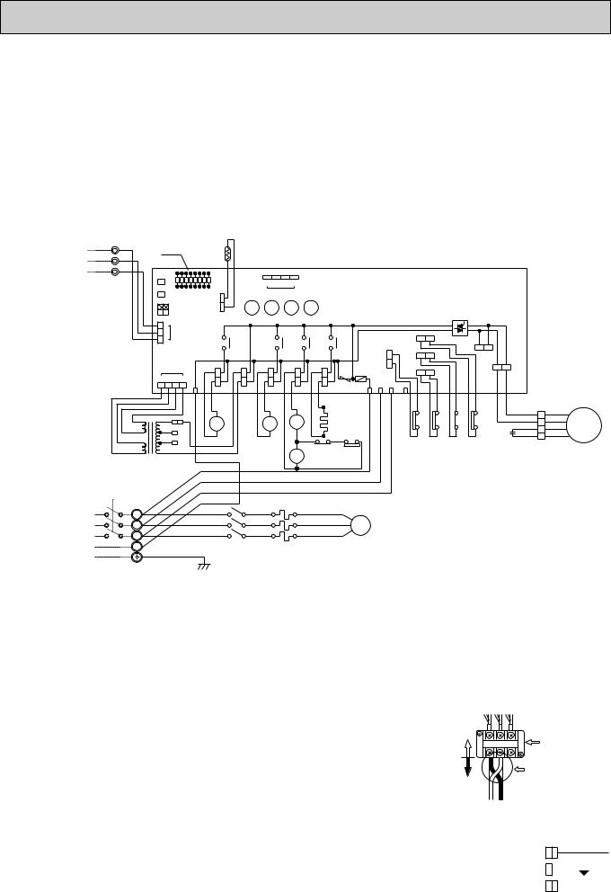
PUH-3YKA2·UK
SYMBOL |
NAME |
SYMBOL |
NAME |
SYMBOL |
NAME |
|
CN3<O.B> |
CONNECTOR (CONNECTING |
O.B |
|
OUTDOOR CONTROLLER BOARD |
ZNR<O.B> |
SURGE ABSORBER |
|
WIRES INDOOR/OUTDOOR) |
< |
> |
SELECT SWITCH(CHECK,SERVICE) |
21R |
BYPASS VALVE SOLENOID COIL |
|
SW1·2·3 O.B |
|
||||
CN4T<O.B> |
CONNECTOR (TRANSFORMER) |
T |
|
TRANSFORMER |
21S4 |
4-WAY VALVE SOLENOID COIL |
C |
FAN MOTOR CAPACITOR |
TB1,3 |
|
TERMINAL BLOCK |
26C |
THERMAL SWITCH |
FC<O.B> |
FAN CONTROLLER |
TH |
|
OUTDOOR COIL TERMISTOR |
51C |
THERMAL RELAY |
F<O.B> |
FUSE(6A) |
X11<O.B> |
CRANKCASE HEATER RELAY |
52C |
COMPRESSOR CONTACTOR |
|
HC |
CRANKCASE HEATER |
X12<O.B> |
COMPRESSOR RELAY |
63H1 |
CONTROL HIGH PRESSURE SWITCH |
|
LD1-LD8<O.B> |
LED(CHECK,SERVICE) |
X13<O.B> |
SOLENOID COIL RELAY |
63H2 |
PROTECTIVE HIGH PRESSURE SWITCH |
|
MC |
COMPRESSOR |
X14<O.B> |
SOLENOID COIL RELAY |
|
|
|
MF |
FAN MOTOR |
X16 |
|
HIGH PRESSURE RELAY |
|
|
TO INDOOR UNIT CONNECTING WIRES DC 12V
POWER SUPPLY 3N~(3PHASE 4WIRES) 380/220—415/240V 50Hz
1 |
YLW |
|
LED |
|
|
|
|
|
|
|
|
|
|
|
|
|
|
|
|
|
|
|
|
|
|
|
|
||
2 |
|
|
|
TH |
|
|
|
|
|
|
|
|
|
|
|
|
|
|
|
|
|
|
|
|
|
|
|||
ORN |
|
|
|
|
|
|
|
|
|
|
|
|
|
|
|
|
|
|
|
|
|
|
|
|
|
|
|
||
O.B |
|
|
|
|
|
|
|
|
|
|
|
|
|
|
|
|
|
|
|
|
|
|
|
|
|
|
|
||
3 |
BRN |
|
|
|
|
|
|
|
|
|
|
|
|
|
|
|
|
|
|
|
|
|
|
|
|
|
|
|
|
|
|
|
|
|
|
|
|
|
|
|
|
|
|
|
|
|
|
|
|
|
|
|
|
|
|
|
|
||
TB3 |
SW1 |
|
|
|
|
|
|
4 |
3 |
2 |
1 |
|
|
|
|
|
|
|
|
|
|
|
|
|
|
|
|
||
SW2 |
|
|
|
|
|
|
|
|
|
|
|
|
|
|
|
|
|
|
|
|
|
|
|||||||
|
|
LD1 LD2 LD3 LD4 LD5 LD6 LD7 LD8 |
|
|
|
|
CN4 |
|
|
|
|
|
|
|
|
|
|
|
|
|
|
|
|
|
|||||
|
|
|
|
|
|
|
|
|
|
|
|
|
|
|
|
|
|
|
|
|
|
|
|
|
|||||
|
|
SW3 |
|
|
|
|
|
|
|
|
|
|
|
|
|
|
|
|
|
|
|
|
|
|
|
||||
|
|
|
|
CN2 |
X14 |
|
X13 |
X12 |
X11 |
|
|
|
|
|
|
|
|
|
|
|
|
|
|
||||||
|
|
|
OFF |
|
|
|
|
|
|
|
|
|
|
|
|
|
|
|
|||||||||||
|
|
|
ON |
|
|
|
|
|
|
|
|
|
|
|
|
|
|
|
|
|
|
|
|
|
|
|
|
||
|
|
2 1 |
|
|
|
|
|
|
|
|
|
|
|
|
|
|
|
|
|
|
|
|
|
|
|
|
|
|
|
|
|
|
3 |
|
|
|
|
|
|
|
|
|
|
|
|
|
|
|
|
|
|
|
|
|
|
|
|
|
|
|
|
|
2 |
CN3 |
|
|
|
|
|
|
|
|
|
|
|
|
|
|
26C |
|
|
|
|
|
|
|
|
|
|
|
|
|
1 |
|
|
|
|
X14 |
|
|
|
X13 |
|
X12 |
X11 |
|
|
|
|
|
|
F.C |
|
|
|
|
|
||
|
|
|
|
|
|
|
|
|
|
|
|
|
|
|
|
|
|
|
MF2 |
|
|
|
|
||||||
|
|
|
|
|
|
|
|
|
|
|
|
|
|
|
|
|
|
|
|
63H2 |
|
|
|
|
|
|
|
||
|
|
|
|
|
|
|
|
|
|
|
|
|
|
|
|
|
|
63H1 |
|
|
|
|
|
|
|
|
|
||
|
|
|
|
|
|
|
|
|
|
|
|
|
|
|
|
|
|
|
|
|
|
|
|
MF1 |
|
|
|
||
|
|
|
CN4T |
|
|
|
|
|
|
|
|
|
|
|
|
|
|
51C |
|
|
|
|
|
|
|
|
|||
|
|
4 |
3 |
2 |
1 |
|
|
|
|
|
|
|
|
|
|
|
|
|
|
|
|
|
|
|
|
|
|
|
|
|
|
|
|
|
|
|
|
|
|
|
|
ZNR |
|
|
|
|
|
|
|
|
|
|
|
|
|
||||
|
|
|
|
|
4 |
|
SV |
TRF |
|
21S4 |
|
52C |
|
F R |
S |
T |
5 |
|
|
|
|
|
|
|
|
|
|||
|
RED |
|
|
|
|
|
|
|
CH |
|
|
|
|
|
|
|
|
|
|
|
|
|
|||||||
|
|
|
|
RED |
RED |
|
BLU |
BLU |
|
GRY |
GRY |
|
WHT |
WHT |
|
|
|
|
BRN BRN |
ORN ORN |
VLT |
VLT |
YLW |
YLW |
|
|
|
|
|
|
RED |
|
|
|
|
|
|
|
|
|
|
|
|
|
|
||||||||||||||
|
BRN |
|
|
|
|
|
|
|
|
|
|
|
|
|
|
||||||||||||||
|
|
|
|
|
|
|
|
|
|
|
|
A1 |
|
|
|
|
|
|
|
96 |
|
1 |
|
WHT 3 |
WHT |
|
|||
|
BRN |
YLW |
|
|
|
|
|
|
|
|
|
|
|
|
|
|
|
|
|
|
|||||||||
|
AC |
|
21R |
|
|
21 |
|
|
52C |
|
HC |
|
|
|
|
63H1 51C |
|
X16 |
26C |
BLU |
4 BLU |
MF |
|||||||
|
12.3V |
ORN 240V |
|
|
S4 |
|
|
A2 |
|
|
|
|
|
|
|
95 |
|
5 |
C |
RED |
2 |
RED |
|||||||
|
|
RED |
230V |
|
|
|
|
|
|
|
|
GRY |
|
|
|
|
|
|
|
|
ORN 1 |
ORN |
|
||||||
|
|
220V |
WHT |
|
|
|
|
|
GRY |
|
|
|
|
|
|
|
|
|
|
|
|
|
|
||||||
|
AC12.3V |
|
|
|
|
|
|
|
|
7 |
6 X16 |
2 |
|
|
|
|
|
|
|
|
|
|
|
|
|
||||
|
|
|
|
|
WHT |
|
|
|
|
|
|
|
|
|
|
|
|
|
|
|
|
|
|
||||||
|
|
|
|
|
|
|
|
|
|
|
X16 |
|
|
63H2 |
|
|
|
|
|
|
|
|
|
|
|
|
|||
|
|
T |
|
|
|
|
|
|
|
|
|
|
|
|
|
|
|
|
|
|
|
|
|
|
|
|
|
|
|
|
|
|
|
|
|
|
|
|
|
|
|
8 |
|
GRY |
|
|
|
|
|
|
|
|
|
|
|
|
|
||
|
|
|
|
|
RED |
|
|
|
|
|
|
|
|
|
|
|
|
|
|
|
|
|
|
|
|
||||
|
|
|
|
|
|
|
|
|
|
|
|
|
|
|
|
|
|
|
|
|
|
|
|
|
|
|
|
||
|
|
|
|
|
WHT |
|
|
|
|
|
|
|
|
|
|
|
|
|
|
|
|
|
|
|
|
|
|
||
|
|
|
|
|
BLK |
|
|
|
|
|
|
|
|
|
|
|
|
|
|
|
|
|
|
|
|
|
|
|
|
|
TB1 |
|
|
|
BLU |
|
|
|
|
|
|
|
|
|
|
|
|
|
|
|
|
|
|
|
|
|
|
|
|
|
|
|
|
RED |
|
L1/1 |
|
|
|
|
|
T1/2 |
RED |
U |
|
|
|
|
|
|
|
|
|
|
|
|
|
||
|
L1 |
|
|
|
|
|
|
|
|
|
|
|
|
|
|
|
|
|
|
|
|
|
|
||||||
|
|
|
|
|
|
|
|
|
|
|
|
|
|
|
|
|
|
|
|
|
|
|
|
|
|
|
|
|
|
|
L2 |
|
|
|
WHT |
L2/3 |
|
|
|
|
|
T2/4 |
WHT |
V |
MC |
|
|
|
|
|
|
|
|
|
|
|
|
||
|
|
|
|
BLK |
|
L3/5 |
|
|
|
|
|
T3/6 |
BLU |
|
|
|
|
|
|
|
|
|
|
|
|
|
|||
|
L3 |
|
|
|
|
|
|
|
|
|
W |
|
|
|
|
|
|
|
|
|
|
|
|
|
|||||
|
|
|
|
|
|
|
52C |
|
|
|
|
|
|
|
|
|
|
|
|
|
|
|
|
|
|
|
|
||
|
N |
|
|
|
|
|
|
|
|
51C |
|
|
|
|
|
|
|
|
|
|
|
|
|
|
|
|
|
||
|
|
|
|
|
|
|
|
|
|
|
|
|
|
|
|
|
|
|
|
|
|
|
|
|
|
|
|||
|
|
|
|
|
|
|
|
|
|
|
|
|
|
|
|
|
|
|
|
|
|
|
|
|
|
|
|
|
|
|
|
GRN/YLW |
|
|
|
|
|
|
|
|
|
|
|
|
|
|
|
|
|
|
|
|
|
|
|
|
|||
Main functions of LED |
( |
when both Nos.1 and 2 of |
SW3 |
) |
|
|
|
|
How to use SW1 and 2 |
|
|
|
|
|
|
|
|
|
|
|
|
|
||||||||||
|
|
are “OFF” |
|
|
|
|
|
|
|
|
|
|
|
|
|
|
|
|
||||||||||||||
|
|
|
|
|
|
|
|
|
|
|
|
|
|
●Pressing |
|
|
|
erases the past check contents loaded on the |
||||||||||||||
|
|
|
|
|
( |
) |
|
|
( |
|
) |
|
SW1 |
|
||||||||||||||||||
LED No. |
Output display |
light |
|
|
|
Check display |
flash |
|
|
microcomputer. |
|
|
|
|
|
|
|
|
|
|
|
|
|
|||||||||
LD1 |
Compressor indoor command |
Anti-phase detect |
|
|
|
|
|
|
|
|
|
|
|
|
|
|
|
|
||||||||||||||
|
|
|
●The output display (light) remains lit during operation but |
|||||||||||||||||||||||||||||
LD2 |
Heating indoor command |
|
|
Missing-phase detect |
|
|
||||||||||||||||||||||||||
|
|
|
|
pressing |
|
SW2 |
|
displays the past check contents in flashing |
||||||||||||||||||||||||
LD3 |
63H1 |
|
|
|
ON |
|
|
Pipe sensor short/open |
|
|
mode. Pressing the switch again returns to output display |
|||||||||||||||||||||
LD4 |
Compressor |
ON |
|
|
|
— |
|
|
|
(light). |
|
|
|
|
|
|
|
|
|
|
|
|
|
|||||||||
LD5 |
Outdoor fan |
ON |
|
|
51C functions |
|
|
|
|
|
|
|
|
Power line reconnoction procedure |
||||||||||||||||||
LD6 |
4-way valve |
ON |
|
|
26C functions |
|
|
|
|
|
|
|
|
In case of reverse rotation |
|
|
|
|||||||||||||||
LD7 |
Bypass valve |
ON |
|
|
TH overheat protection |
|
|
|
|
|
|
|
|
|
|
|
|
|
|
|
|
|
|
|
|
|
||||||
LD8 |
Crankcase heater |
ON |
|
|
Defective input |
|
|
|
|
|
Unit side |
|
|
|
|
|
Outdoor unit |
|||||||||||||||
|
|
|
|
|
|
|
|
|
|
|
|
|
|
|
|
L1 L2 L3 |
||||||||||||||||
NOTE : If the operation stops to function of the protection device, the check display flashes. |
|
|
wiring |
|||||||||||||||||||||||||||||
|
|
terminal |
||||||||||||||||||||||||||||||
|
|
|
|
|
|
|
|
|
|
|
||||||||||||||||||||||
|
|
|
|
|
|
|
|
|
|
|
|
|
|
|
|
|
|
|
|
|
|
Change 2 out of 1. |
||||||||||
CAUTIONS FOR SERVICING |
|
|
|
|
|
|
|
|
|
|
|
|
|
|
|
|
|
|
|
|
|
|||||||||||
|
|
|
|
|
|
|
|
|
|
|
|
|
|
|
|
|
|
|
|
|
|
|
|
|
2 and 3. |
|
|
|
||||
Connect the lead wires according to the color indication of sticker on the compressor terminal. |
|
|
Field wiring |
|
|
|
|
|
|
|
|
|||||||||||||||||||||
|
|
|
|
|
|
|
(This example shows |
|||||||||||||||||||||||||
● |
|
|
|
|
|
|
|
|
|
|
|
|
|
|
|
|
|
|
|
|
|
|
|
|
|
|
|
|
|
|
|
|
|
|
|
|
|
|
|
|
|
|
|
|
|
|
|
|
|
|
|
|
|
|
|
|
|
reconnection of 1 |
|||||||
CAUTIONS FOR POWER SUPPLY WIRING |
|
|
|
|
|
|
|
|
|
Change thie side |
|
|
|
|
and 2.) |
|
|
|
||||||||||||||
|
|
|
|
|
|
|
|
|
|
|
|
|
|
|
|
|
|
|
|
|
1 2 3 |
|
|
|
|
|
|
|
|
|||
Making wiring connection in anti-phase or missing phase “A2” or “A3” causes the protection device incorporated in the |
|
|
|
|
|
|
|
|
|
|||||||||||||||||||||||
|
|
|
|
|
|
|
|
|
|
|
|
|
||||||||||||||||||||
● |
|
|
|
|
|
|
|
|
|
|
|
|
|
|
|
|
|
|
|
|
|
|
|
|
|
|
|
|
|
|
|
|
microcomputer to function resulting in LD1 or LD2 shown in the table above to flash and prevents the compressor |
|
|
wWhen power supply is 220V |
|||||||||||||||||||||||||||||
operation. If phase “A1” or “N” is missing it causes all displays to go out. Under normal condition LD8 light when power |
|
|
||||||||||||||||||||||||||||||
|
|
|
|
|
|
|
|
|
|
|
|
|
||||||||||||||||||||
is turned “ON”. If anti-phase connection is to be used, change connections of 2 out of 3 power lines (field wiring side) |
|
|
YELLOW |
|
|
|
|
|
|
|
|
|||||||||||||||||||||
|
|
240V |
|
|
|
|
|
|
|
|||||||||||||||||||||||
contained in the power supply terminal block (TB1) of the outdoor unit as shown at the right upper. |
|
|
|
|
|
|
|
|
|
|
|
|
|
|
||||||||||||||||||
|
|
|
|
|
|
|
ORANGE |
|
|
|
|
|
|
|
|
|||||||||||||||||
|
|
|
|
|
|
|
|
|
|
|
|
|
|
|
||||||||||||||||||
wSince the transformer (T) is connected with 240V power, if 220V or 230V power is used, change the wiring connection |
|
230V |
|
|
|
|
|
|
||||||||||||||||||||||||
in the following procedure. |
|
|
|
|
|
|
|
|
|
|
|
|
|
|
|
|
|
|
|
|
RED |
|
|
|
|
|
|
|
|
|||
|
|
|
|
|
|
|
|
|
|
|
|
|
|
|
|
|
|
|
|
|
|
|
|
|
WHITE |
|||||||
|
|
|
|
|
|
|
|
|
|
|
|
|
|
|
|
|
|
|
|
|
|
220V |
|
|
|
|
||||||
CAUTION FOR INDOOR AND OUTDOOR CONNECTING WIRES |
|
|
|
|
|
|
|
|
|
|
|
|
|
|
|
|
|
|
|
|
|
|
|
|||||||||
|
|
|
|
|
|
|
|
|
|
|
|
|
|
|
|
|
|
|
|
|
|
|||||||||||
●Since the indoor and outdoor connecting wires has polarity, make sure to connect the same terminal numbers (1,2,3) for indoor and outdoor units.
12
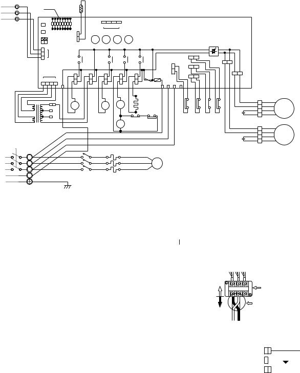
|
|
|
|
|
|
|
PUH-4YKSA ·UK |
|
|
|
|
|
|
|
2 |
|
|
|
|
|
|
|
|
|
|
|
|
SYMBOL |
NAME |
SYMBOL |
NAME |
SYMBOL |
NAME |
|
CN3<O.B> |
CONNECTOR (CONNECTING |
O.B |
|
OUTDOOR CONTROLLER BOARD |
ZNR<O.B> |
SURGE ABSORBER |
|
WIRES INDOOR/OUTDOOR) |
< |
> |
SELECT SWITCH(CHECK,SERVICE) |
21R |
BYPASS VALVE SOLENOID COIL |
|
SW1·2·3 O.B |
|
||||
CN4T<O.B> |
CONNECTOR (TRANSFORMER) |
T |
|
TRANSFORMER |
21S4 |
4-WAY VALVE SOLENOID COIL |
C1,2 |
FAN MOTOR CAPACITOR |
TB1,3 |
|
TERMINAL BLOCK |
26C |
THERMAL SWITCH |
FC<O.B> |
FAN CONTROLLER |
TH |
|
OUTDOOR COIL TERMISTOR |
51C |
THERMAL RELAY |
F<O.B> |
FUSE(6A) |
X11<O.B> |
CRANKCASE HEATER RELAY |
52C |
COMPRESSOR CONTACTOR |
|
HC |
CRANKCASE HEATER |
X12<O.B> |
COMPRESSOR RELAY |
63H1 |
CONTROL HIGH PRESSURE SWITCH |
|
LD1-LD8<O.B> |
LED(CHECK,SERVICE) |
X13<O.B> |
SOLENOID COIL RELAY |
63H2 |
PROTECT HIGH PRESSURE SWITCH |
|
MC |
COMPRESSOR |
X14<O.B> |
SOLENOID COIL RELAY |
|
|
|
MF1,2 |
FAN MOTOR |
X16 |
|
HIGH PRESSURE RELAY |
|
|
TO INDOOR UNIT CONNECTING WIRES DC 12V
POWER SUPPLY 3N~(3PHASE 4WIRES) 380/220 — 415/240V 50Hz
1 |
YLW |
|
LED |
|
|
|
|
|
|
|
|
|
|
|
|
|
|
|
|
|
|
|
|
|
|
|
|
||
2 |
|
|
TH3 |
|
|
|
|
|
|
|
|
|
|
|
|
|
|
|
|
|
|
|
|
|
|
||||
ORN |
|
|
|
|
|
|
|
|
|
|
|
|
|
|
|
|
|
|
|
|
|
|
|
|
|
|
|||
O.B |
|
|
|
|
|
|
|
|
|
|
|
|
|
|
|
|
|
|
|
|
|
|
|
|
|
|
|||
3 |
BRN |
|
|
|
|
|
|
|
|
|
|
|
|
|
|
|
|
|
|
|
|
|
|
|
|
|
|
||
|
|
|
|
|
|
|
|
|
|
|
|
|
|
|
|
|
|
|
|
|
|
|
|
|
|
|
|
||
TB3 |
SW1 |
|
|
|
|
|
|
4 |
3 |
2 |
1 |
|
|
|
|
|
|
|
|
|
|
|
|
|
|
|
|
||
SW2 |
|
|
|
|
|
|
|
|
|
|
|
|
|
|
|
|
|
|
|
|
|
|
|||||||
|
|
LD1 LD2 LD3 LD4 LD5 LD6 LD7 LD8 |
|
|
|
|
CN4 |
|
|
|
|
|
|
|
|
|
|
|
|
|
|
|
|
|
|||||
|
|
|
|
|
|
|
|
|
|
|
|
|
|
|
|
|
|
|
|
|
|
|
|
|
|||||
|
|
SW3 |
|
|
|
|
|
|
|
|
|
|
|
|
|
|
|
|
|
|
|
|
|
|
|
||||
|
|
|
|
|
|
|
|
|
|
|
|
|
|
|
|
|
|
|
|
|
|
|
|
|
|
|
|
||
|
|
|
OFF |
CN2 |
X14 |
|
X13 |
X12 |
X11 |
|
|
|
|
|
|
|
|
|
|
|
|
|
|
||||||
|
|
|
ON |
|
|
|
|
|
|
|
|
|
|
|
|
|
|
|
|
|
|
|
|
|
|
|
|
||
|
|
2 1 |
|
|
|
|
|
|
|
|
|
|
|
|
|
|
|
|
|
|
|
|
|
|
|
|
|
|
|
|
|
|
3 |
|
|
|
|
|
|
|
|
|
|
|
|
|
|
|
|
|
|
|
|
|
|
|
|
|
|
|
|
|
2 |
CN3 |
|
|
|
|
|
|
|
|
|
|
|
|
|
|
26C |
|
|
|
|
|
|
|
|
|
|
|
|
|
1 |
|
|
|
|
X14 |
|
|
|
X13 |
|
X12 |
X11 |
|
|
|
|
|
|
|
F.C |
|
|
|
|||
|
|
|
|
|
|
|
|
|
|
|
|
|
|
|
|
|
|
|
|
|
|
||||||||
|
|
|
|
|
|
|
|
|
|
|
|
|
|
|
|
|
|
|
|
|
|
|
|
|
MF2 |
|
|
|
|
|
|
|
|
|
|
|
|
|
|
|
|
|
|
|
|
|
|
63H1 |
|
63H2 |
|
|
|
|
|
|
|
|
|
|
|
|
|
|
|
|
|
|
|
|
|
|
|
|
|
|
|
|
|
|
|
|
|
|
|
MF1 |
|
|
|
|
|
|
CN4T |
|
|
|
|
|
|
|
|
|
|
|
|
|
|
51C |
|
|
|
|
|
|
|
|
|||
|
|
|
|
|
|
|
|
|
|
|
|
|
|
|
|
|
|
|
|
|
|
|
|
|
|
||||
|
|
|
|
|
|
|
|
|
|
|
|
|
|
|
|
|
|
|
|
|
|
|
|
|
|
|
|
|
|
|
|
4 |
3 |
2 |
1 |
|
|
|
|
|
|
|
|
|
|
|
|
|
|
|
|
|
|
|
|
|
|
|
|
|
|
|
|
|
4 |
|
SV |
TRF |
|
21S4 |
|
52C |
CH |
ZNR |
F R |
S |
T |
5 |
|
|
|
|
|
|
|
|
|
||
|
RED |
|
|
|
|
|
|
|
|
|
|
|
|
|
|
|
|
|
|
|
|
|
|||||||
|
|
|
|
RED |
RED |
|
BLU |
BLU |
|
GRY |
GRY |
|
WHT |
WHT |
|
|
|
|
BRN BRN |
ORN |
ORN |
VLT |
VLT |
YLW |
YLW |
|
|
|
|
|
RED |
|
|
|
|
|
|
|
|
|
|
|
|
|
|||||||||||||||
|
BRN |
|
|
|
|
|
|
|
|
|
|
|
|
A1 |
|
|
|
|
|
|
|
|
96 |
|
1 |
|
|
|
|
|
BRN |
YLW |
|
|
|
|
|
|
|
|
|
|
|
|
|
|
|
|
|
|
|
BLUWHT 3 |
BLUWHT |
||||||
|
AC |
|
21R |
|
|
21 |
|
|
52C |
HC |
|
|
|
63H1 |
|
51C |
|
X16 |
26C |
||||||||||
|
12.3V |
ORN 240V |
|
|
|
|
S4 |
|
|
|
A2 |
|
|
|
|
|
|
|
|
95 |
|
5 |
|
RED |
4 |
RED |
|||
|
|
RED |
230V |
|
|
|
|
|
|
|
|
GRY |
|
|
|
|
|
|
|
|
|
C1 |
ORN |
2 |
ORN |
||||
|
|
220V |
WHT |
|
|
|
|
|
|
GRY |
|
|
|
|
|
|
|
|
|
1 |
|||||||||
|
AC12.3V |
|
|
|
|
|
|
|
|
|
7 |
6 X16 2 |
63H2 |
|
|
|
|
|
|
|
|
|
|
|
|
||||
|
|
|
|
|
WHT |
|
|
|
|
|
|
|
|
|
|
|
|
|
|
|
|
|
|
||||||
|
|
T |
|
|
|
|
|
|
|
|
|
|
X16 |
|
|
|
|
|
|
|
|
|
|
|
|
WHT |
|
WHT |
|
|
|
|
|
RED |
|
|
|
|
|
|
|
8 |
GRY |
|
|
|
|
|
|
|
|
|
|
|
3 |
||||
|
|
|
|
|
|
|
|
|
|
|
|
|
|
|
|
|
|
|
|
|
|
|
|
|
BLU |
4 |
BLU |
||
|
|
|
|
|
|
|
|
|
|
|
|
|
|
|
|
|
|
|
|
|
|
|
|
|
|
|
BRN |
RED |
|
|
|
|
|
|
WHT |
|
|
|
|
|
|
|
|
|
|
|
|
|
|
|
|
|
|
C2 |
YLW |
2 |
ORN |
||
|
|
|
|
|
BLK |
|
|
|
|
|
|
|
|
|
|
|
|
|
|
|
|
|
|
|
|
|
1 |
|
|
|
TB1 |
|
|
|
BLU |
|
|
|
|
|
|
|
|
|
|
|
|
|
|
|
|
|
|
|
|
|
|
|
|
|
|
|
|
RED |
L1/1 |
|
|
|
|
|
|
T1/2 |
RED |
U |
|
|
|
|
|
|
|
|
|
|
|
|
|
||
|
L1 |
|
|
|
|
|
|
|
|
|
|
|
|
|
|
|
|
|
|
|
|
|
|
||||||
|
|
|
|
|
|
|
|
|
|
|
|
|
|
|
|
|
|
|
|
|
|
|
|
|
|
|
|
|
|
|
L2 |
|
|
|
WHT |
L2/3 |
|
|
|
|
|
|
T2/4 |
WHT |
V |
MC |
|
|
|
|
|
|
|
|
|
|
|
||
|
|
|
|
BLK |
|
L3/5 |
|
|
|
|
|
|
T3/6 |
BLU |
|
|
|
|
|
|
|
|
|
|
|
|
|||
|
L3 |
|
|
|
|
|
|
|
|
|
|
W |
|
|
|
|
|
|
|
|
|
|
|
|
|
||||
|
|
|
|
|
|
|
52C |
|
|
|
|
|
|
|
|
|
|
|
|
|
|
|
|
|
|
|
|
||
|
N |
|
|
|
|
|
|
|
|
51C |
|
|
|
|
|
|
|
|
|
|
|
|
|
|
|
|
|
||
|
|
|
|
|
|
|
|
|
|
|
|
|
|
|
|
|
|
|
|
|
|
|
|
|
|
|
|||
|
|
|
|
|
|
|
|
|
|
|
|
|
|
|
|
|
|
|
|
|
|
|
|
|
|
|
|
|
|
|
|
GRN/YLW |
|
|
|
|
|
|
|
|
|
|
|
|
|
|
|
|
|
|
|
|
|
|
|
|
|||
MF1
MF2
Main functions of LED |
( |
when both Nos.1 and 2 of |
SW3 |
) |
|
|
|
|
How to use SW1 and 2 |
|
|
|
|
|
|
|
|
|
|
|
|
|
|||||||||||
|
are “OFF” |
|
|
|
|
|
|
|
|
|
|
|
|
|
|
|
|
||||||||||||||||
|
|
|
|
|
|
|
|
|
|
|
|
|
|
|
●Pressing |
|
erases the past check contents loaded on the |
||||||||||||||||
|
|
|
|
|
|
( |
) |
|
|
( |
|
) |
|
SW1 |
|||||||||||||||||||
LED No. |
Output display |
light |
|
|
|
|
Check display |
flash |
|
|
microcomputer. |
|
|
|
|
|
|
|
|
|
|
|
|
|
|||||||||
|
LD1 |
Compressor indoor command |
|
Anti-phase detect |
|
|
|
|
|
|
|
|
|
|
|
|
|
|
|
|
|||||||||||||
|
|
|
|
|
●The output display (light) remains during operation but |
||||||||||||||||||||||||||||
|
LD2 |
Heating indoor command |
|
|
|
Missing-phase detect |
|
|
|||||||||||||||||||||||||
|
|
|
|
|
|
|
|
|
|
displays the past check contents in flashing |
|||||||||||||||||||||||
|
|
|
|
|
pressingSW2 |
|
|||||||||||||||||||||||||||
|
LD3 |
63H1 |
|
|
|
ON |
|
|
|
Pipe sensor short/open |
|
|
|
|
|
|
|
|
|
|
|
|
|
|
|
|
|
|
|
|
|||
|
|
|
|
|
|
|
|
mode. Pressing the switch again returns to output display |
|||||||||||||||||||||||||
|
LD4 |
Compressor |
ON |
|
|
|
|
— |
|
|
|
(light). |
|
|
|
|
|
|
|
|
|
|
|
|
|
|
|
||||||
|
LD5 |
Outdoor fan |
ON |
|
|
|
51C functions |
|
|
|
|
|
|
|
Power line reconnoction procedure |
||||||||||||||||||
|
LD6 |
4-way valve |
ON |
|
|
|
26C functions |
|
|
|
|
|
|
|
In case of reverse rotation |
|
|
|
|||||||||||||||
|
LD7 |
Bypass valve |
ON |
|
|
|
TH overheat protection |
|
|
|
|
|
|
|
|
|
|
|
|
|
|
|
|
|
|
|
|
||||||
|
LD8 |
Crankcase heater |
ON |
|
|
|
Defective input |
|
|
|
|
|
|
Unit side |
|
|
|
|
|
Outdoor unit |
|||||||||||||
|
|
|
|
|
|
|
|
|
|
|
|
|
|
|
|
|
|
|
L1 L2 L3 |
||||||||||||||
NOTE : If the operation stops to function of the protection device, the check display flashes. |
|
|
|
wiring |
|||||||||||||||||||||||||||||
|
|
|
terminal |
||||||||||||||||||||||||||||||
|
|
|
|
|
|
|
|
|
|
||||||||||||||||||||||||
|
|
|
|
|
|
|
|
|
|
|
|
|
|
|
|
|
|
|
|
|
|
Change 2 out of 1. |
|||||||||||
CAUTIONS FOR SERVICING |
|
|
|
|
|
|
|
|
|
|
|
|
|
|
|
|
|
|
|
|
|
||||||||||||
|
|
|
|
|
|
|
|
|
|
|
|
|
|
|
|
|
|
|
|
|
|
|
|
|
|
2 and 3. |
|
|
|
||||
|
Connect the lead wires according to the colo indication of sticker on the compressor terminal. |
|
|
|
Field wiring |
|
|
|
|
|
|
|
|
||||||||||||||||||||
● |
|
|
|
|
|
|
|
|
(This example shows |
||||||||||||||||||||||||
|
|
|
|
|
|
|
|
|
|
|
|
|
|
|
|
|
|
|
|
|
|
|
|
|
|
reconnection of 1 |
|||||||
CAUTIONS FOR POWER SUPPLY WIRING |
|
|
|
|
|
|
|
|
|
|
|
Change thie side |
|
|
|
|
and 2.) |
|
|
|
|||||||||||||
|
|
|
|
|
|
|
|
|
|
|
|
|
|
|
|
|
|
|
|
|
|
1 2 3 |
|
|
|
|
|
|
|
|
|||
●Making wiring connection in anti-phase or missing phase “A2” or “A3” causes the protection device incorporated in the |
|
|
|
|
|
|
|
|
|
||||||||||||||||||||||||
|
|
|
|
|
|
|
|
|
|
|
|
|
|||||||||||||||||||||
|
microcomputer to function resulting in LD1 or LD2 shown in the table above to flash and prevents the compressor |
|
|
wWhen power supply is 220V |
|||||||||||||||||||||||||||||
|
operation. If phase “A1” or “N” is missing it causes all displays to go out. Under normal condition LD8 light when power |
|
|
||||||||||||||||||||||||||||||
|
|
|
|
|
|
|
|
|
|
|
|
|
|
||||||||||||||||||||
|
is turned “ON”. If anti-phase connection is to be used, change connections of 2 out of 3 power lines (field wiring side) |
|
|
YELLOW |
|
|
|
|
|
|
|
|
|||||||||||||||||||||
|
|
|
240V |
|
|
|
|
|
|
|
|||||||||||||||||||||||
|
contained in the power supply terminal block (TB1) of the outdoor unit as shown at the right upper. |
|
|
|
|
|
|
|
|
|
|
|
|
|
|||||||||||||||||||
|
|
|
|
|
|
|
ORANGE |
|
|
|
|
|
|
|
|
||||||||||||||||||
|
|
|
|
|
|
|
|
|
|
|
|
|
|
|
|||||||||||||||||||
wSince the transformer (T) is connected with 240V power, if 220V or 230V power is used, change the wiring connection |
|
230V |
|
|
|
|
|
|
|||||||||||||||||||||||||
|
in the following procedure. |
|
|
|
|
|
|
|
|
|
|
|
|
|
|
|
|
|
|
|
|
RED |
|
|
|
|
|
|
|
|
|||
|
|
|
|
|
|
|
|
|
|
|
|
|
|
|
|
|
|
|
|
|
|
|
|
|
|
WHITE |
|||||||
|
|
|
|
|
|
|
|
|
|
|
|
|
|
|
|
|
|
|
|
|
|
|
220V |
|
|
|
|
||||||
CAUTION FOR INDOOR AND OUTDOOR CONNECTING WIRES |
|
|
|
|
|
|
|
|
|
|
|
|
|
|
|
|
|
|
|
|
|
|
|||||||||||
|
|
|
|
|
|
|
|
|
|
|
|
|
|
|
|
|
|
|
|
|
|||||||||||||
●Since the indoor and outdoor connecting wires has polarity, make sure to connect the same terminal numbers (1,2,3) for indoor and outdoor units.
13
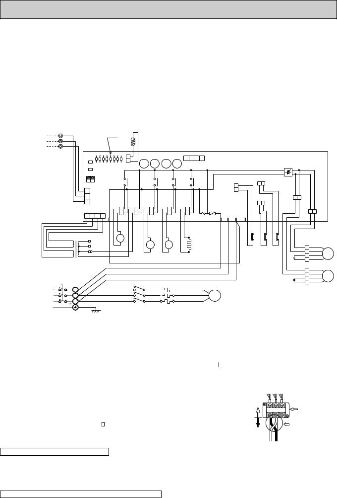
PUH-4TKSA1·UK
SYMBOL |
NAME |
SYMBOL |
NAME |
SYMBOL |
NAME |
CN3<O.B> |
CONNECTOR (CONNECTING |
MF1,2 |
FAN MOTOR |
X14<O.B> |
SOLENOID COIL RELAY |
|
WIRES INDOOR/OUTDOOR) |
O.B |
OUTDOOR CONTROLLER BOARD |
ZNR<O.B> |
SURGE ABSORBER |
CN4T<O.B> |
CONNECTOR (TRANSFORMER) |
SW1·2·3<O.B> |
SELECT SWITCH(CHECK,SERVICE) |
21R |
BYPASS VALVE SOLENOID COIL |
C1,2 |
FAN MOTOR CAPACITOR |
T |
TRANSFORMER |
21S4 |
4-WAY VALVE SOLENOID COIL |
FC<O.B> |
FAN CONTROLLER |
TB1,3 |
TERMINAL BLOCK |
26C |
THERMAL SWITCH |
F<O.B> |
FUSE(6A) |
RT |
OUTDOOR COIL TERMISTOR |
51C |
THERMAL RELAY |
HC |
CRANKCASE HEATER |
X11<O.B> |
CRANKCASE HEATER RELAY |
52C |
COMPRESSOR CONTACTOR |
LD1-LD8 |
LED(CHECK,SERVICE) |
X12<O.B> |
COMPRESSOR RELAY |
63H1 |
HIGH PRESSURE SWITCH |
MC |
COMPRESSOR |
X13<O.B> |
SOLENOID COIL RELAY |
|
|
TO INDOOR UNIT CONNECTING WIRES DC 12V (polar)
1 |
YLW |
|
LED |
|
|
|
|
|
|
2 |
ORN |
|
|
|
|
|
|
|
|
|
|
RT |
|
|
|
|
|
||
3 |
BRN |
|
|
|
|
|
|
|
|
|
|
|
|
|
|
|
|
||
TB3 |
O.B |
|
|
|
|
|
|
|
|
|
|
|
|
|
|
|
|
|
|
|
SW1 |
|
|
|
|
|
4 |
3 2 1 |
|
|
SW2 |
LD1 |
LD2 LD3 LD4 LD5 LD6 LD7 LD8 |
CN2 |
X14 |
X13 X12 |
X11 |
CN4 |
|
|
|
|
|
|
|
||||
|
|
|
|
|
|
|
|
||
|
SW3 |
OFF |
|
|
|
|
|
|
|
|
|
|
|
|
|
26C |
F.C. |
||
|
|
ON |
X14 |
|
X13 |
X12 |
|||
|
2 1 |
|
|
|
X11 |
|
|||
|
|
|
|
|
|
|
|
|
|
3 |
|
63H1 |
|
|
MF2 |
||
2 |
CN3 |
||
51C |
|||
1 |
|
||
|
|
|
|
CN4T |
|
|
|
|
|
|
|
|
|
|
|
|
|
F |
|
|
|
|
|
|
MF1 |
||
|
|
|
|
|
|
|
|
|
|
|
|
|
|
|
|
|
|
|
|
|
|
|
|||
|
4 |
3 |
2 |
1 |
4 |
|
SV |
|
TRF |
21S4 |
|
|
52C |
|
CH |
ZNR R S T 5 |
|
|
|
|
|
|
|
|
|
|
|
|
|
|
|
|
|
|
|
|
|
|
|
|
|
|
|
|
|||||||
|
|
|
|
BLU |
RED |
RED |
WHT |
WHT |
BLU |
BLU |
GRY |
GRY |
WHT |
WHT |
|
|
BRN |
BRN |
ORN ORN |
YLW |
YLW |
|
|
|
|
|
|
|
|
|
|
|
|
|
|
|
|
|
|
|
|
|
|
|
|
96 |
|
|
|
|
|
|
YLW |
240V |
|
|
|
21R |
|
|
|
|
|
A1 |
|
|
|
|
|
|
95 |
|
|
|
|
|
|
|
|
|
|
|
|
|
|
21 |
|
|
|
|
HC |
|
|
|
|
|
|
|
|
||||
BRN AC12.3V |
ORN |
230V |
|
|
|
|
|
|
|
|
52C |
|
|
|
|
|
|
|
|
|
|
||||
|
|
|
|
|
|
|
S4 |
|
|
|
63H1 |
51C |
|
26C |
WHT |
3 |
WHT |
|
|||||||
|
RED |
|
|
|
|
|
|
|
|
|
|
|
A2 |
|
|
|
|
BLU |
BLU |
|
|||||
RED AC12.3V |
|
220V |
|
|
|
|
|
|
|
|
|
|
|
|
|
|
|
|
|
|
RED |
4 |
RED |
MF1 |
|
|
|
|
|
|
|
|
|
|
|
|
|
|
|
|
|
|
|
|
2 |
||||||
|
|
|
|
|
|
|
|
|
|
|
|
|
|
|
|
|
|
|
|
||||||
|
T |
|
|
|
|
|
|
|
|
|
|
|
|
|
|
|
|
|
|
|
C1 |
ORN |
1 |
ORN |
|
|
|
|
|
RED |
|
|
|
|
|
|
|
|
|
|
|
|
|
|
|
|
|
|
|
||
|
|
|
|
|
|
|
|
|
|
|
|
|
|
|
|
|
|
|
|
|
WHT |
|
WHT |
|
|
|
|
|
|
|
WHT |
|
|
|
|
|
|
|
|
|
|
|
|
|
|
|
|
3 |
|
||
|
|
|
|
|
|
|
|
|
|
|
|
|
|
|
|
|
|
|
|
|
|
BLU |
4 |
BLU |
MF2 |
|
|
|
|
|
BLK |
|
|
|
|
|
|
|
|
|
|
|
|
|
|
|
C2 |
BRN |
RED |
||
|
TB1 |
|
|
|
|
|
|
|
|
|
|
|
|
|
|
|
|
|
|
|
YLW |
2 |
ORN |
|
|
|
|
|
|
|
|
|
|
|
|
|
|
|
|
|
|
|
|
|
|
|
|
1 |
|
|
|
POWER SUPPLY |
L1 |
|
|
|
RED |
|
L1/1 |
|
|
|
|
|
T1/2 |
RED |
|
U |
|
|
|
|
|
|
|
|
|
|
|
|
|
|
L2/3 |
|
|
|
|
|
T2/4 |
WHT |
V |
|
|
|
|
|
|
|
|
||||
3~(3PHASE) |
L2 |
|
|
|
WHT |
|
|
|
|
|
|
MC |
|
|
|
|
|
|
|
|
|||||
|
|
|
BLK |
|
L3/5 |
|
|
|
|
|
T3/6 |
BLU |
|
|
|
|
|
|
|
|
|
||||
220V 60Hz |
L3 |
|
|
|
|
|
|
|
|
|
|
W |
|
|
|
|
|
|
|
|
|||||
|
|
|
|
|
|
|
|
|
|
|
|
|
|
|
|
|
|
|
|
|
|
|
|||
|
|
|
GRN/YLW |
|
|
|
52C |
|
|
51C |
|
|
|
|
|
|
|
|
|
|
|
|
|||
|
|
|
|
|
|
|
|
|
|
|
|
|
|
|
|
|
|
|
|
|
|
|
|
||
Main functions of LED |
( |
when both Nos.1 and 2 of |
SW3 |
) |
How to use SW1 and 2 |
|
|
|
|
|
|||||||||||
|
|
are “OFF” |
|
|
|
|
|
||||||||||||||
|
|
|
|
|
|
|
|
|
|
|
●Pressing |
|
erases the past check contents loaded on the |
||||||||
LED No. |
Output display (light) |
|
Check display (flash) |
SW1 |
|||||||||||||||||
|
microcomputer. |
|
|
|
|
|
|||||||||||||||
LD1 |
Compressor indoor command |
Anti-phase detect |
|
|
|
|
|
||||||||||||||
●The output display (light) remains during operation but |
|||||||||||||||||||||
LD2 |
Heating indoor command |
Missing-phase detect |
|||||||||||||||||||
|
|
|
|
displays the past check contents in flashing |
|||||||||||||||||
pressingSW2 |
|
||||||||||||||||||||
LD3 |
63H1 |
|
|
|
|
|
|
ON |
Pipe sensor short/open |
|
|
|
|
|
|
|
|
|
|
||
|
|
|
|
|
|
mode. Pressing the switch again returns to output display |
|||||||||||||||
LD4 |
Compressor |
ON |
|
— |
(light). |
|
|
|
|
|
|
|
|||||||||
LD5 |
Outdoor fan |
ON |
51C functions |
|
|
|
|
Power line reconnoction procedure |
|||||||||||||
LD6 |
4-way valve |
ON |
26C functions |
|
|
|
|
In case of reverse rotation |
|||||||||||||
LD7 |
Bypass valve |
ON |
RT overheat protection |
|
|
|
|
|
|
|
|
|
|
||||||||
LD8 |
Crankcase heater |
ON |
Defective input |
|
|
|
Unit side |
|
|
|
|
Outdoor unit |
|||||||||
|
|
|
|
|
|
|
|
|
|
|
|
|
|
L1 L2 L3 |
|||||||
NOTES : 1. If the operation of the protection device stops to function. then check the display flashes. |
wiring |
||||||||||||||||||||
terminal |
|||||||||||||||||||||
|
|
|
|
|
|
||||||||||||||||
2. Symblos used in wiring diagram above are. |
|
|
|
|
|
|
|
|
|
|
Change 2 out of 1. |
||||||||||
|
|
|
|
|
|
|
|
|
|
||||||||||||
|
/:Terminal block |
|
|
|
|
:Connector :PC board insertion tab. |
|
|
|
|
|
|
|
|
|
||||||
|
|
|
|
|
|
|
|
|
|
|
|
|
|
2 and 3. |
|||||||
|
|
|
|
|
|
|
|
|
|
|
|
|
|
||||||||
|
|
|
|
|
|
|
|
|
|
|
|
|
|
Field wiring |
|
|
|
|
(This example shows |
||
CAUTIONS FOR SERVICING |
|
|
|
|
|
|
|
|
|
|
|
|
|
reconnection of 1 |
|||||||
|
|
|
|
|
|
|
|
|
|
|
|
|
|
Change thie side |
|
|
|
and 2.) |
|||
Connect the lead wires according to the colo indication of sticker on the compressor terminal. |
|
|
|
||||||||||||||||||
● |
|
|
|
|
|
|
|
|
|
|
|
|
|
|
|
1 2 3 |
|
||||
|
|
|
|
|
|
|
|
|
|
|
|
|
|
|
|
|
|||||
CAUTIONS FOR POWER SUPPLY WIRING
●Making wiring connection in anti-phase or missing phase “A2” or “A3” causes the protection device incorporated in the microcomputer to function resulting in LD1 or LD2 shown in the table above to flash and prevents the compressor operation. If phase “A1” or “N” is missing it causes all displays to go out. Under normal condition LD8 light when power is turned “ON”. If anti-phase connection is to be used, change connections of 2 out of 3 power lines (field wiring side) contained in the power supply terminal block (TB1) of the outdoor unit as shown at the right upper.
CAUTION FOR INDOOR AND OUTDOOR CONNECTING WIRES
●Since the indoor and outdoor connecting wires has polarity, make sure to connect the same terminal numbers (1,2,3) for indoor and outdoor units.
14
 Loading...