


PMFY-P20VBM-A
Mitsubishi PMFY-P20VBM-A, PMFY-P20VBM-A1, PMFY-P25VBM-A, PMFY-P25VBM-A1, PMFY-P32VBM-A Service Manual
...
TECHNICAL & SERVICE MANUAL
SPLIT-TYPE,HEAT PUMP AIR CONDITIONERS
Indoor unit
[Model names] [Service Ref.]
PMFY-P20VBM-A PMFY-P20VBM-A
PMFY-P20VBM-A
1
PMFY-P25VBM-A PMFY-P25VBM-A
PMFY-P25VBM-A
1
PMFY-P32VBM-A PMFY-P32VBM-A
PMFY-P32VBM-A
1
PMFY-P40VBM-A PMFY-P40VBM-A
PMFY-P40VBM-A
1
No. OC248
REVISED EDITION-A
INDOOR UNIT
Ceiling Cassettes
Series PMFY
CONTENTS
1. TECHNICAL CHANGE·························2
2. SAFETY PRECAUTION ·······················2
3. PART NAMES AND FUNCTIONS········4
4. SPECIFICATION···································6
5. OUTLINES AND DIMENSIONS··········10
6. WIRING DIAGRAM·····························11
7.
REFRIGERANT SYSTEM DIAGRAM
···12
8. TROUBLE SHOOTING ·······················13
9. DISASSEMBLY PROCEDURE ···········19
10. PARTS LIST········································22
R407C
2001
R22
• PMFY-P20VBM-A1,
PMFY-P25VBM-A1,
PMFY-P32VBM-A1,
PMFY-P40VBM-A1
are added in
Revised Edition-A.
• Please destroy OC248.

2
1
TECHNICAL CHANGES
SAFETY PRECAUTION
2
Cautions for using with the outdoor unit which adopts R407C refrigerant.
· Do not use the existing refrigerant piping.
-The old refrigerant and lubricant in the existing piping contains a large amount of chlorine which may cause the lubricant
deterioration of the new unit.
· Use “low residual oil piping”.
-If there is a large amount of residual oil (hydraulic oil, etc.) inside the piping and joints, deterioration of the lubricant will result.
· Store the piping to be used during installation indoors with keep both ends sealed until just before brazing.
(Store elbows and other joints in a plastic bag.)
-If dust, dirt, or water enters the refrigerant cycle, deterioration of the oil and compressor trouble may result.
· Use ESTR , ETHER or HAB as the lubricant to coat flares and flange connection parts.
Use liquid refrigerant to seal the system.
-If gas refrigerant is used to seal the system, the composition of the refrigerant in the cylinder will change and performance
may drop.
· Do not use a refrigerant other than R407C.
-If another refrigerant (R22, etc.) is used, the chlorine in the refrigerant may cause the lubricant deterioration.
· Use a vacuum pump with a reverse flow check valve.
-The vacuum pump oil may flow back into the refrigerant cycle and cause the lubricant deterioration.
PMFY-P20VBM-A PMFY-P20VBM-A1
PMFY-P25VBM-A PMFY-P25VBM-A1
PMFY-P32VBM-A PMFY-P32VBM-A1
PMFY-P40VBM-A PMFY-P40VBM-A1
● INDOOR CONTROLLER BOARD(I.B) has changed.
● DRAIN PAN has changed.
3
[3] Refrigerant recharging
(1) Refrigerant recharging process
1Direct charging from the cylinder.
·R407C cylinder are available on the market has a syphon pipe.
·Leave the syphon pipe cylinder standing and recharge by liquid refrigerant
.
(2) Recharge in refrigerant leakage case
·After recovering the all refrigerant in the unit, proceed to working.
·Do not release the refrigerant in the air.
·After completing the repair service, recharge the cycle with the specified amount of
liquid refrigerant.
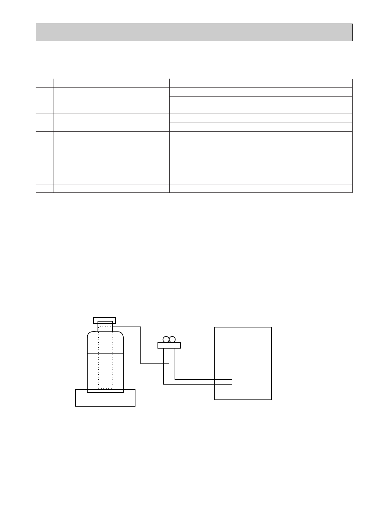
[1] Service tools
Use the below service tools as exclusive tools for R407C refrigerant.
No. Tool name Specifications
1 Gauge manifold ·Only for R407C.
·Use the existing fitting SPECIFICATIONS. (UNF7/16)
·Use high-tension side pressure of 3.43MPa·G or over.
2 Charge hose ·Only for R407C.
·Use pressure performance of 5.10MPa·G or over.
3 Electronic scale
4 Gas leak detector ·Use the detector for R134a or R407C.
5 Adapter for reverse flow check. ·Attach on vacuum pump.
6 Refrigerant charge base.
7 Refrigerant cylinder. ·For R407C ·Top of cylinder (Brown)
·Cylinder with syphon
8 Refrigerant recovery equipment.
[2] Notice on repair service
·After recovering the all refrigerant in the unit, proceed to working.
·Do not release refrigerant in the air.
·After completing the repair service, recharge the cycle with the specified amount of
liquid refrigerant.
Gravimeter
Unit
4
3
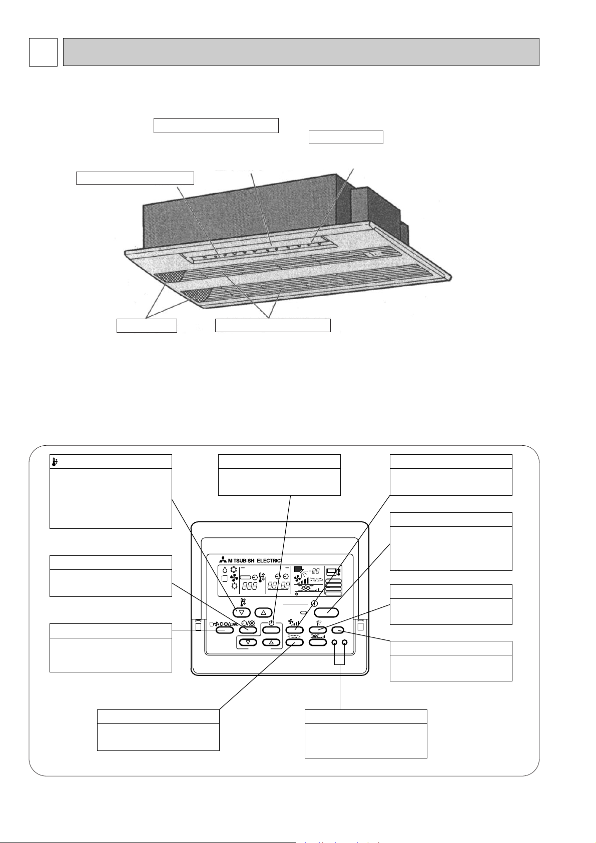
PART NAMES AND FUNCTIONS
● Indoor (Main) Unit
● Remote controller
● Operation buttons
[PAR-20MAA]
● Once the controls are set, the same operation mode can
be repeated by simply pressing the ON/OFF button.
PAR-20MAA
ON/OFF
CENTRALLY CONTROLLED
ERROR CODE
CLOCK
ON OFF
˚C
CHECK
CHECK MODE
FILTER
TEST RUN
FUNCTION
˚C
1Hr.
NOT AVAILABLE
STAND BY
DEFROST
FILTER
CHECK TEST
TEMP.
TIMER SET
Press this button to switch the cooler,
electronic dry (dehumidify), automatic
and heater modes.
OPERATION SWITCH button
This sets the room temperature. The
temperature setting can be performed
in 1: units
Setting range
Cooler 19: to 30:
Heater 17: to 28:
TEMP. ADJUSTMENT button
This switches between continuous
operation and the timer operation.
TIMER button
This switches between the operation
and stop modes each time it is pressed.
The lamp on this button lights during
operation.
ON/OFF button
Only press this button to perform an
inspection check or test operation.
Do not use it for normal operation.
CHECK-TEST RUN button
This switch the horizontal fan motion
ON and OFF.
(Not available for this model.)
LOUVER button
This adjusts the vertical angle of the
ventilation.
AIR DIRECTION button
This resets the filter service indication
display
FILTER button
This sets the current time, start time
and stop time.
TIME SETTING button
This sets the ventilation fan speed.
AIR SPEED button
Guide vane
Air flow can be changed to horizontally
by moving the Guide vane to the left or right.
Air intake
Returns air from room.
Filters
Remove dust and pollutants
from return air.
Auto Air Swing Vane
Disperses airflow up and
down and adjusts the angle
of airflow direction.
Horizontal Air Outlet

5
Caution
● Only the Power display lights when the unit is stopped and power supplied to the unit.
● When the central control remote control unit, which is sold separately, is used the ON-OFF button, operation switch button
and TEMP. adjustment button do not operate.
● “NOT AVAILABLE” is displayed when the Air speed button are pressed.This indicates that this room unit is not equipped
with the fan direction adjustment function and the louver function.
● When power is turned ON for the first time, it is normal that “H0” is displayed on the room temperature indication (For max.
2minutes). Please wait until this “H0” indication disappear then start the operation.
CENTRALLY
CONTROLLED display
This indicates when the unit is con-
trolled by optional features such as
central control type remote controller.
TIMER display
This indicates when the continuous
operation and time operation modes
are set.
It also display the time for the timer
operation at the same time as when
it is set.
OPERATION MODE display
This indicates the operation mode.
STANDBY display
The [STANDBY] symbol is only
displayed from the time the heating
operation starts unit the heated air
begins to blow.
DEFROST display
This indicates when the defrost oper-
ation is performed.
CHECK display
This indicates when a malfunction
has occurred in the unit which should
be checked.
CLOCK display
The current time , start time and stop
time can be displayed in ten second
intervals by pressing the time switch
button. The start time or stop time is
always displayed during the timer
operation.
● Display
In this display example on the bot-
tom left, a condition where all dis-
play lamps light is shown for expla-
nation purposes although this differs
from actual operation.
Operation lamp
This lamp lights during operation,
goes off when the unit stops and
flashes when a malfunction occurs.
POWER display
This lamp lights when electricity is
supplied to the unit.
SET TEMPERATURE display
This displays the selected setting
temperature.
AIR DIRECTION display
This displays the air direction.
ROOM TEMPERATURE display
The temperature of the suction air
is displayed during operation. The
display range is 8°C to 39°C. The
display flashes 8°C when the actual
temperature is less than 8°C and
flashes 39°C when the actual tem-
perature is greater than 39°C.
display
This display lights in the check mode
or when a test operation is per-
formed.
CHECK MODE
TEST RUN
This lamp lights when the filter need
to be cleaned.
AIR SPEED display
The selected fan speed is displayed.
FILTER display
PAR-20MAA
ON/OFF
CENTRALLY CONTROLLED
ERROR CODE
CLOCK
ON OFF
˚C
CHECK
CHECK MODE
FILTER
TEST RUN
FUNCTION
˚C
1Hr.
NOT AVAILABLE
STAND BY
DEFROST
FILTER
CHECK TEST
TEMP.
TIMER SET
6
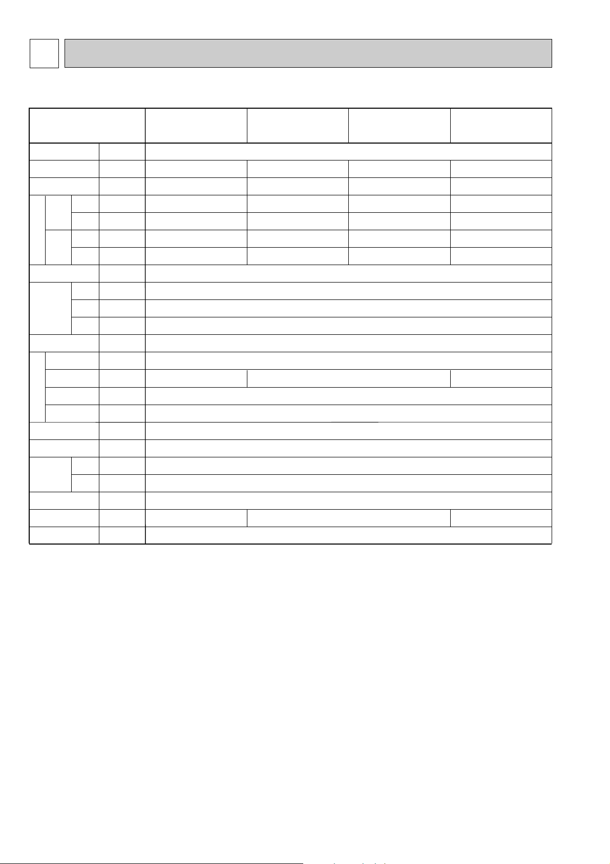
4
SPECIFICATION
4-1. Specification
Note 1. Rating conditions
Cooling: Indoor: D.B. 27°C W.B. 19.0°C
outdoor: D.B. 35°C
Heating: Indoor: D.B. 20°C
outdoor: D.B. 7°C W.B. 6°C
Note 2. The number indicated in < > is just for the grille.
W 3. Air flow and the noise level are indicated as High-Middium 1-Middium 2-Low.
Item
V
·Hz
kW
kW
kW
kW
A
A
—
mm
mm
mm
—
—
k/min
Pa
kW
—
—
[mm(in.)
[mm(in.)
[mm
dB
kg
Cooling capacity
Power
Heat exchanger
Insulator
Air filter
Fan ✕ No
Air flow W3
Pipe
dimensions
Unit drain pipe size
Noise level W3
Product weight
Exterior
(munsell symbol)
Fan motor
output
External
static pressure
Liquid
side
Gas
side
Heating capacity
F
a
n
Dimensions
Height
Width
Depth
Electric characteristic
Input
Cooling
Heating
Cooling
Heating
Current
PMFY-P20VBM-A
PMFY-P20VBM-A
1
PMFY-P25VBM-A
PMFY-P25VBM-A
1
PMFY-P32VBM-A
PMFY-P32VBM-A
1
PMFY-P40VBM-A
PMFY-P40VBM-A
1
Single phase 220V-230V-240V 50Hz / 220V 60Hz
2.2
2.5
0.042
0.042
0.20
0.20
2.8
3.2
0.044
0.044
0.21
0.21
3.6
4.0
0.044
0.044
0.21
0.21
4.5
5.0
0.054
0.054
0.26
0.26
9.3-8.6-8.0-7.3
37-36-34-32
8.7-8.0-7.2-6.5
35-33-30-27
10.7-9.7-8.7-7.7
39-37-35-33
Unit : Galvanized sheets · Standard grills : ABS resin acrylic coating Munsell<0.98Y 8.99/0.63>
230<30>
812<1,000>
395<470>
Cross fin
Line flow fan ✕ 1
0
0.028
Polyethylene sheet
PP honey comb fabric
12.7(1/2")
6.35(1/4")
I.D.26 (PVC pipe VP-20 connectable)
14<3.0>
7
4-2. Electrical parts specifications
Parts name
Model
Symbol
TH21
TH22
TH23
FUSE
MF
MV
DP
DS
LEV
TB2
TB5
TB15
Resistance 0:/15k", 10:/9.6k", 20:/6.3k", 25:/5.2k", 30:/4.3k", 40:/3.0k"
Resistance 0:/15k", 10:/9.6k", 20:/6.3k", 25:/5.2k", 30:/4.3k", 40:/3.0k"
Resistance 0:/15k", 10:/9.6k", 20:/6.3k", 25:/5.2k", 30:/4.3k", 40:/3.0k"
250V 6.3A
Thermistor resistance 0:/6k", 10:/3.9k", 20:/2.6k", 25:/2.2k", 30:/1.8k", 40:/1.3k"
(L, N, ;) 330V 30A
(M1, M2, S) 250V 20A
(1,2) 250V 10A
Liquid pipe thermistor
Gas pipe thermistor
Drain-up mechanism
Drain sensor
Linear expansion valve
PMFY-P20VBM-A
PMFY-P20VBM-A
1
PMFY-P25VBM-A
PMFY-P25VBM-A
1
PMFY-P32VBM-A
PMFY-P32VBM-A
1
PMFY-P40VBM-A
PMFY-P40VBM-A
1
Room temperature
thermistor
Fuse
(Indoor controller board)
Fan motor
Vane motor
Power supply
terminal block
Transmission
terminal block
DC Brushless Motor
8-pole OUTPUT 28W
PN0H28-MA
MSFJC 20M23
12V/380
"
PJV-1046
220-240V 50/60Hz
DC12V Stepping motor drive port
(0~2000pulse)
EDM-402ME
MA-remote controller
terminal block
8
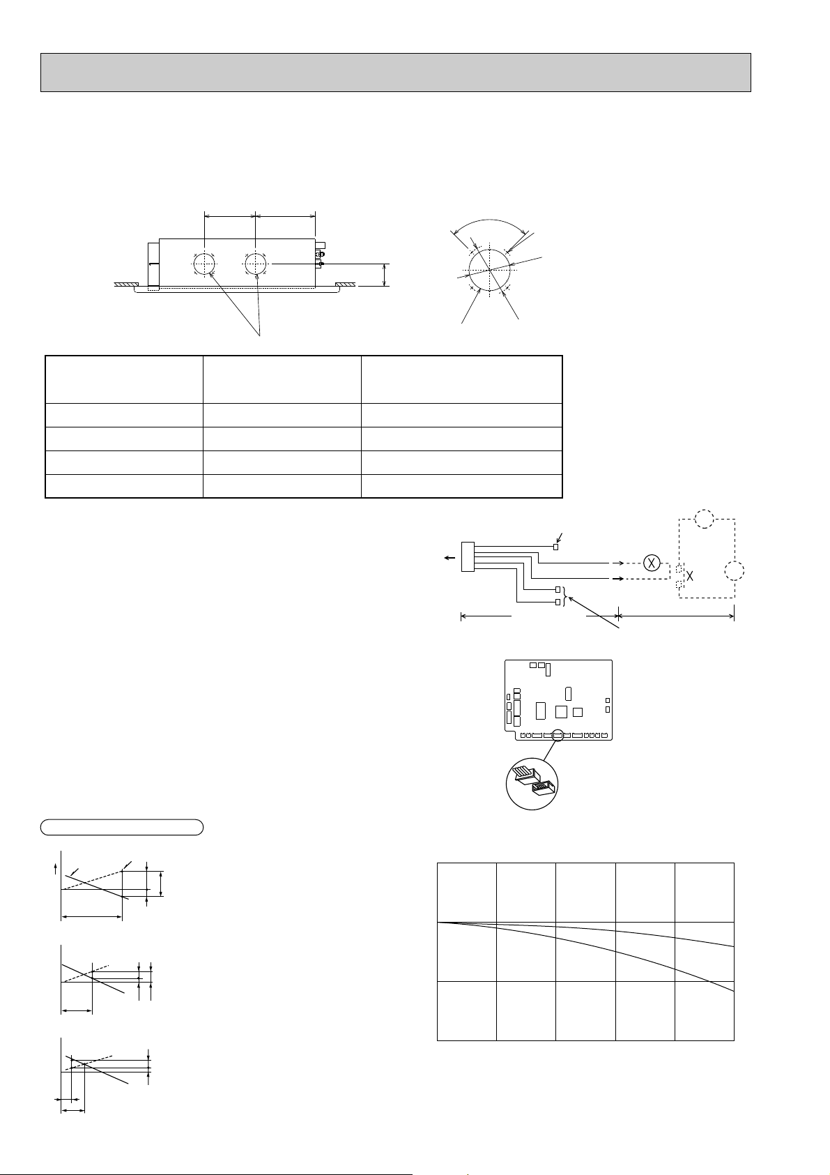
4-3. Air capacity taken from outside
50.0
-50.0
-100.0
0.0 0.5 1.0
Air flow (m
3
/min)
2 intakes
1 intake
Characteristic diagram of air capacity taken from outside of PMFY-P·VBM
Static pressure (Pa)
1.5 2.0 2.5
0.0
PMFY-P20VBM-A
PMFY-P20VBM-A
1
PMFY-P25VBM-A
PMFY-P25VBM-A
1
PMFY-P32VBM-A
PMFY-P32VBM-A
1
PMFY-P40VBM-A
PMFY-P40VBM-A
1
8.7m
3
/min
9.3m
3
/min
9.3m
3
/min
10.7m
3
/min
Max 1.74m
3
/min
Max 1.86m
3
/min
Max 1.86m
3
/min
Max 2.14m
3
/min
Air flow
(Hi)
Air capacity taken outside
Service Ref.
PMFY-P·VBM-A series are possible to be taken air from outside.
When taking air from the outside, the duct fan can be used to.
The air capacity should be 20% or less of the air flow SPEC(Hi).
Q…Planned amount of fresh air intake
A…Static pressure loss of fresh air
intake duct system with air flow
amount Q
B…Forced static pressure at air condi-
tioner inlet with air flow amount Q
C…Static pressure of booster fan with
air flow amount Q
D…Static pressure loss increase
amount of fresh air intake dust
system for air flow amount Q
<Pa>
E…Static pressure of indoor unit with
air flow amount Q
Qa…Estimated amount of fresh air
intake with out D <m
3
/min>
<m
3
/min>
<Pa>
<Pa>
<Pa>
<Pa>
(Knock out)
4-{2.8
Fresh air intake hole
(Knock out)
Fresh air intake hole
90-
{
122
{
100
108
250 288.5
Installation at site
1
~
CN51
Multiple remote
controller adapter
PAC-SA88HA-E
Indoor controller board
Distance between indoor
controller board and relay
must be within 10m.
Be sure to secure insulation
material by tape and such
5
Green
Yellow
Orange
Connector (5P)
Package side
Multiple remote
controller adapter
PAC-SA88HA-E
Be sure to secure insulation
material by tape and such
CN51
on
indoor unit
board
Red
Brown
MB
Q
0
B
A
C
1
2
3
Curve in the
rigth graphs.
Duct characteristics
at site
Q
A
E C
Q
Qa
A D
Interlocking operation method with duct fan
(Booster fan)
●Whenever the indoor unit is operating, the duct fun also
operates.
(1)Connect the optional multiple remote controller
adapter(PAC-SA88HA-E)to the connector CN51 on the
indoor controller board.
(2)Drive the relay after connecting the 12V DC relay
between the Yellow and Orange connector lines.
(w)Use a relay under 1W.
MB: Electromagnetic switch power relay for duct fan.
X: Auxiliary relay (12V DC LY-1F)
How to read curves
 Loading...