


AIR CONDITIONERS
MODEL
PQHY-P Y(S)HM-A
PQRY-P Y(S)HM-A
- For ground source application
DATA BOOK
Preface
DATABOOK describes the technical specifications of MITSUBISHI ELECTRIC Corp.'s CITYMULTI air conditioning system products.
In this DATABOOK for ground source application, information on water-cooled heat source unit PQHY-P Y(S)HM-A/ PQRY-P Y(S)HM-A, with the connection of standard CITY MULTI indoor unit series, Air to Water series, and Close Control PFD series are specified.
We recommend DATABOOK users to read carefully and take advantage of all the contents inside to design the CITY MULTI air conditioning system and/or to prepare documents for promotions.
Along with the DATABOOK, MITSUBISHI ELECTRIC provides a Design-Tool software to ensure the users to design the system correctly and simplify the calculations. Please contact your local distributor for this software.
Please be notified that specifications are subject to change without notice due to continual improvements of the product.
For any inquiries, please contact your local distributor.
i

Contents
I |
Brine information |
|
|
|
1. Brine freezing temperature ........................................................................................................ |
1 |
|
|
2. Capacity correction by brine concentration (For heat source unit) ...................................... |
2 |
|
|
3. Pressure drop correction by brine concentration (For heat source unit) ............................. |
3 |
|
II |
Heat source unit information |
|
|
|
1. General lineup of water-cooled heat source unit .................................................................... |
4 |
|
|
2. PQHY-P-Y(S)HM-A ...................................................................................................................... |
5 |
|
|
(1)Specification .............................................................................................................................................. |
5 |
|
|
(1)-1 Heat source units specification for standard combination |
|
|
|
|
(Standard CITY MULTI indoor units, PWFY-P100/200VM-E-AU) .................................................. |
5 |
|
(1)-2 System specification for closed control system (PFD-P250/500VM-E) ....................................... |
19 |
|
|
(2)External dimension .................................................................................................................................. |
21 |
|
|
(3)Center of gravity ...................................................................................................................................... |
24 |
|
|
(4)Electrical wiring diagram .......................................................................................................................... |
25 |
|
|
(5)Sound levels ............................................................................................................................................ |
26 |
|
|
(6)Capacity tables with indoor units ............................................................................................................. |
30 |
|
|
(6)-1 Cooling capacity with standard indoor units ................................................................................. |
30 |
|
|
(6)-2 Heating capacity with standard indoor units ................................................................................. |
43 |
|
|
(7)Correction by total indoor ......................................................................................................................... |
44 |
|
|
(8)Correction by refrigerant piping length ..................................................................................................... |
46 |
|
|
(9)Correction by water temperature (For heat source unit) .......................................................................... |
49 |
|
|
(9)-1 Connection with standard CITY MULTI indoor units .................................................................... |
49 |
|
|
(9)-2 Connection with PWFY-P100/200VM-E-AU (HEX unit) ............................................................... |
49 |
|
|
(9)-3 |
Connection with PFD-P250/500VM-E .......................................................................................... |
50 |
|
(10)Correction by water flow rate (For heat source unit) .............................................................................. |
51 |
|
|
(10)-1 Connection with standard CITY MULTI indoor units .................................................................... |
51 |
|
|
(10)-2 Connection with PWFY-P100/200VM-E-AU (HEX unit) ............................................................... |
51 |
|
|
(10)-3 |
Connection with PFD-P250/500VM-E .......................................................................................... |
51 |
|
(11)Correction by indoor temperature .......................................................................................................... |
52 |
|
|
(11)-1 Connection with standard CITY MULTI indoor units .................................................................... |
52 |
|
|
(11)-2 Connection with PWFY-P100/200VM-E-AU (HEX unit) ............................................................... |
52 |
|
|
(11)-3 Connection with PFD-P250/500VM-E .......................................................................................... |
52 |
|
|
(12)Correction by water flow rate (For PWFY-P100/200VM-E-AU (HEX unit)) ............................................ |
53 |
|
|
(12)-1 Connection with PWFY-P100VM-E-AU (HEX unit) ...................................................................... |
53 |
|
|
(12)-2 Connection with PWFY-P200VM-E-AU (HEX unit) ...................................................................... |
53 |
|
|
(13)Water pressure drop correction by water volume ................................................................................. |
54 |
|
|
(13)-1 Heat source unit correction |
|
|
|
|
(Connection with Standard CITY MULTI indoor units, PWFY-P100/200VM-E-AU, |
|
|
|
PFD-P250/500VM-E) ................................................................................................................... |
54 |
|
(13)-2 HEX unit correction (Connection with PWFY-P100/200VM-E-AU) .............................................. |
54 |
|
|
(13)-3 Water pressure drop of strainer only (accessory for PWFY-P100/200VM-E-AU) ........................ |
54 |
|
|
(14)Operation temperature range ................................................................................................................ |
55 |
|
|
(14)-1 Connection with standard CITY MULTI indoor units .................................................................... |
55 |
|
|
(14)-2 Connection with PWFY-P100/200VM-E-AU (HEX unit) ............................................................... |
55 |
|
|
(14)-3 Connection with PFD-P250/500VM-E .......................................................................................... |
56 |
|
|
(15)Piping design ......................................................................................................................................... |
57 |
|
|
(15)-1 R410A Piping material .................................................................................................................. |
57 |
|
|
(15)-2 PQHY-P200-300YHM Piping |
|
|
|
|
(Connection with standard CITY MULTI indoor units, PWFY-P100/200VM-E-AU) ...................... |
58 |
|
(15)-3 PQHY-P400-600YSHM Piping |
|
|
|
|
(Connection with standard CITY MULTI indoor units, PWFY-P100/200VM-E-AU) ...................... |
59 |
|
(15)-4 PQHY-P650-900YSHM Piping |
|
|
|
|
(Connection with standard CITY MULTI indoor units, PWFY-P100/200VM-E-AU) ...................... |
60 |
|
(15)-5 PQHY-P250/P250+P250YHM |
|
|
|
|
(Connection with PFD indoor unit) ............................................................................................... |
61 |
|
(15)-6 Refrigerant charging calculation ................................................................................................... |
62 |
|

3. PQRY-P-Y(S)HM-A .................................................................................................................... |
63 |
(1)Specification ............................................................................................................................................ |
63 |
(1)-1 Heat source units specification for standard combination |
|
(Standard CITY MULTI indoor units, PWFY-P100VM-E-BU, PWFY-P100/200VM-E-AU) .......... |
63 |
(2)External dimension .................................................................................................................................. |
71 |
(3)Center of gravity ...................................................................................................................................... |
73 |
(4)Electrical wiring diagram .......................................................................................................................... |
74 |
(5)Sound levels ............................................................................................................................................ |
75 |
(6)Capacity tables with indoor units ............................................................................................................. |
77 |
(6)-1 Cooling capacity with standard indoor units ................................................................................. |
77 |
(6)-2 Heating capacity with standard indoor units ................................................................................. |
90 |
(7)Correction by total indoor ......................................................................................................................... |
91 |
(8)Correction by refrigerant piping length ..................................................................................................... |
92 |
(9)Correction by port counts of the BC controller ........................................................................................ |
93 |
(10)Correction by water temperature (For heat source unit) ........................................................................ |
94 |
(10)-1 Connection with standard CITY MULTI indoor units .................................................................... |
94 |
(10)-2 Connection with PWFY-P100/200VM-E-AU (HEX unit) ................................................................ |
94 |
(10)-3 Connection with PWFY-P100VM-E-BU (Booster unit) ................................................................. |
95 |
(10)-4 Connection with PWFY-P100VM-E-BU (Booster unit) + WCB Energy saving mode* ................. |
96 |
(11)Correction by water flow rate (For heat source unit) .............................................................................. |
97 |
(11)-1 Connection with standard CITY MULTI indoor units .................................................................... |
97 |
(11)-2 Connection with PWFY-P100/200VM-E-AU (HEX unit) ............................................................... |
97 |
(11)-3 Connection with PWFY-P100VM-E-BU (Booster unit) ................................................................. |
97 |
(12)Correction by indoor temperature .......................................................................................................... |
98 |
(12)-1 Connection with standard CITY MULTI indoor units .................................................................... |
98 |
(12)-2 Connection with PWFY-P100/200VM-E-AU (HEX unit) ............................................................... |
98 |
(12)-3 Connection with PWFY-P100VM-E-BU (Booster unit) ................................................................. |
98 |
(13)Correction by water flow rate |
|
(For PWFY-P100/200VM-E-AU (HEX unit) and PWFY-P100VM-E-BU (Booster unit) ........................... |
98 |
(13)-1 Connection with PWFY-P100VM-E-AU (HEX unit) ..................................................................... |
98 |
(13)-2 Connection with PWFY-P200VM-E-AU (HEX unit) ...................................................................... |
99 |
(13)-3 Connection with PWFY-P100VM-E-BU (Booster unit) ................................................................. |
99 |
(14)Water pressure drop correction by water volume ............................................................................... |
100 |
(14)-1 Heat source unit correction |
|
(Connection with Standard CITY MULTI indoor units, PWFY-P100/200VM-E-AU, |
|
PWFY-P100VM-E-BU) ............................................................................................................... |
100 |
(14)-2 Booster unit correction (Connection with PWFY-P100VM-E-BU) .............................................. |
100 |
(14)-3 HEX unit correction (Connection with PWFY-P100/200VM-E-AU) ............................................ |
100 |
(14)-4 Water pressure drop of strainer only |
|
(accessory for PWFY-P100VM-E-BU and PWFY-P100/200VM-E-AU) ..................................... |
101 |
(15)Operation temperature range .............................................................................................................. |
102 |
(15)-1 Connection with standard CITY MULTI indoor units .................................................................. |
102 |
(15)-2 Connection with PWFY-P100VM-E-BU (Booster unit) ............................................................... |
102 |
(15)-3 Connection with PWFY-P100/200VM-E-AU (HEX unit) ............................................................. |
103 |
(16)Piping design ....................................................................................................................................... |
104 |
(16)-1 R410A Piping material ................................................................................................................ |
104 |
(16)-2 PQRY-P200-300YHM Piping |
|
IF 16 ports or less are in use, i.e., if only one BC controller is in use with no sub BC controller |
|
(Connection with standard CITY MULTI indoor units, PWFY-P100VM-E-BU, |
|
PWFY-P100/200VM-E-AU) ........................................................................................................ |
105 |
(16)-3 PQRY-P200-300YHM Piping |
|
IF more than 16 ports are in use, or if there is more than one BC controller in use for |
|
one Heat source unit |
|
(Connection with standard CITY MULTI indoor units, PWFY-P100VM-E-BU, |
|
PWFY-P100/200VM-E-AU) ........................................................................................................ |
106 |
(16)-4 PQRY-P400YHM Piping |
|
IF more than 16 ports are in use, or if there is more than one BC controller in use for |
|
two heat source units |
|
(Connection with standard CITY MULTI indoor units, PWFY-P100VM-E-BU, |
|
PWFY-P100/200VM-E-AU) ........................................................................................................ |
107 |
(16)-5 Total piping length restrictions .................................................................................................... |
108 |
(16)-6 Refrigerant charging calculation ................................................................................................. |
109 |

I Brine information
1.Brine freezing temperature
Brine concentration is decided by the freezing temperature. First, it is necessary to decide the freezing temperature and find out brine concentration which will correspond to the freezing temperature.
Freezing Temperature [deg°C]
10
0
Propylene Glycol
-10
-20
Ethylene Glycol
-30
-40
-50
0 |
10 |
20 |
30 |
40 |
50 |
60 |
70 |
80 |
90 |
100 |
Brine concentration [wt%]
Note;
The graph was referred from chemical company data.
But Freezing Temperature condition will be slightly different based on each company. Please confirm detail data to the chemical company directly.
It is recommended to set the brine concentration to a percentage that will keep the freezing temperature at -15deg°C or less.
- 1 -
2.Capacity correction by brine concentration (For heat source unit)
Depending on the freezing temperature and brine concentration, the ratio of unit capacity will change. As shown in the line diagram, higher the brine concentration, the lower the ratio of capacity becomes.
Cooling
|
1 |
|
|
|
|
PQHY |
|
|
|
|
|
PQRY |
|
capacity |
|
|
|
|
Ethylene Glycol |
|
0.95 |
|
Propylene Glycol |
|
|
||
|
|
|
|
|||
cooling |
|
|
|
|
||
0.9 |
|
|
|
|
|
|
Ratio of |
|
|
|
|
|
|
0.85 |
|
|
|
|
|
|
|
|
|
|
|
|
|
|
0% |
20% |
40% |
60% |
80% |
100% |
|
|
|
Brine concentration [wt%] |
|
||
|
1.30 |
|
|
|
|
|
input |
1.25 |
|
|
|
|
|
1.20 |
|
|
|
|
|
|
cooling |
1.15 |
|
Propylene Glycol |
|
|
|
|
|
|
|
|||
of |
1.10 |
|
|
|
||
|
|
|
|
|
||
Ratio |
1.05 |
|
|
|
Ethylene Glycol |
|
|
1.00 |
|
|
|
|
|
|
|
|
|
|
|
|
|
0% |
20% |
40% |
60% |
80% |
100% |
|
|
|
Brine concentration [wt%] |
|
||
Heating
|
1.00 |
|
|
|
|
|
|
|
|
|
|
|
|
|
|
|
|
|
|
|
|
|
|
|
|
|
|
|
capacity |
0.95 |
|
|
|
|
|
|
|
|
|
|
|
|
|
|
|
|
|
|
|
|
|
Ethylene |
Glycol |
|
|
|
|
|
|
|
|
|
|
|
|
|
|
|
|
|
|
|
|
|
|
|
|
|
|
|
|
|
|
|
||
|
|
|
|
|
|
|
|
|
|
|
|
|
|
|
|
|
|
|
|
|
|
|
|
|
||||
0.90 |
|
|
|
|
|
|
|
|
|
|
|
|
|
|
|
|
|
|
|
|
|
|
|
|
|
|
|
|
|
|
|
|
|
|
|
|
|
|
|
|
|
|
|
|
|
|
|
|
|
|
|
|
|
|
|
||
|
|
|
|
|
|
|
|
|
|
|
|
|
|
|
|
|
|
|
|
|
|
|
|
|
|
|
||
|
|
|
|
|
|
|
|
|
|
|
|
|
|
|
|
|
|
|
|
|
|
|
|
|
|
|
||
|
|
|
|
|
|
|
|
|
|
|
|
|
|
|
|
|
|
|
|
|
|
|
|
|
|
|
|
|
|
|
|
|
|
|
|
|
|
|
|
|
|
|
|
|
|
|
|
|
|
|
|
|
|
|
|
|
|
heating |
0.80 |
|
|
|
|
|
|
|
|
|
|
|
|
Propylene |
|
Glycol |
|
|
|
|
|
|
|
|
|
|||
of |
0.85 |
|
|
|
|
|
|
|
|
|
|
|
|
|
|
|
|
|
|
|
|
|
|
|
|
|
|
|
|
|
|
|
|
|
|
|
|
|
|
|
|
|
|
|
|
|
|
|
|
|
|
|
|
||||
|
|
|
|
|
|
|
|
|
|
|
|
|
|
|
|
|
|
|
|
|
|
|
|
|
|
|
|
|
|
|
|
|
|
|
|
|
|
|
|
|
|
|
|
|
|
|
|
|
|
|
|
|
|
|
|
|
|
|
|
|
|
|
|
|
|
|
|
|
|
|
|
|
|
|
|
|
|
|
|
|
|
|
|
|
|
|
|
|
|
|
|
|
|
|
|
|
|
|
|
|
|
|
|
|
|
|
|
|
|
|
|
|
|
|
|
|
|
|
|
|
|
|
|
|
|
|
|
|
|
|
|
|
|
|
|
|
|
|
|
|
|
|
|
|
|
|
|
|
|
|
|
|
|
|
|
|
|
|
|
|
|
|
|
|
|
|
|
|
|
|
|
|
|
|
|
|
|
|
|
|
|
|
|
|
|
|
|
|
|
|
|
|
|
|
|
|
|
|
|
|
|
|
|
|
|
|
|
|
|
|
|
|
|
|
|
|
|
|
|
|
|
|
|
|
|
|
|
|
|
|
|
Ratio |
0.75 |
|
|
|
|
|
|
|
|
|
|
|
|
|
|
|
|
|
|
|
|
|
|
|
|
|
|
|
|
|
|
|
|
|
|
|
|
|
|
|
|
|
|
|
|
|
|
|
|
|
|
|
|
|
|
||
|
|
|
|
|
|
|
|
|
|
|
|
|
|
|
|
|
|
|
|
|
|
|
|
|
|
|
|
|
|
0.70 |
|
|
|
|
|
|
|
|
|
|
|
|
|
|
|
|
|
|
|
|
|
|
|
|
|
|
|
|
|
|
|
|
|
|
|
|
|
|
|
|
|
|
|
|
|
|
|
|
|
|
|
|
|
|
|
|
|
|
|
|
|
|
|
|
|
|
|
|
|
|
|
|
|
|
|
|
|
|
|
|
|
|
|
|
|
|
|
|
|
|
|
|
|
|
|
|
|
|
|
|
|
|
|
|
|
|
|
|
|
|
|
|||
|
|
|
|
|
|
|
|
|
|
|
|
|
|
|
|
|
|
|
|
|
|
|
|
|
|
|||
|
0% |
20% |
40% |
|
|
|
60% |
80% |
100% |
|||||||||||||||||||
|
|
|
|
|
|
|
|
|
|
|
|
Brine concentration [wt%] |
|
|
|
|
||||||||||||
|
|
|
|
|
|
|
|
|
|
|
|
|
|
|
|
|
|
|
|
|
|
|
|
|
|
|
|
|
|
|
|
|
|
|
|
|
|
|
|
|
|
|
|
|
|
|
|
|
|
|
|
|
|
|
|
|
|
|
1 |
|
|
|
|
|
|
|
|
|
|
|
|
|
|
|
|
|
|
|
|
|
|
|
|
|
|
|
|
|
|
|
|
|
|
|
|
|
|
|
|
|
|
|
|
|
|
|
|
|
|
|
|
|
|
|
|
|
|
|
|
|
|
|
|
|
|
|
|
|
|
|
|
|
|
|
|
|
|
|
|
|
|
|||
|
|
|
|
|
|
|
|
|
|
|
|
|
|
|
|
|
|
|
|
|
|
|
|
|
|
|
|
|
input |
0.95 |
|
|
|
|
|
|
|
|
|
|
|
|
|
|
|
|
|
|
|
|
|
Ethylene |
Glycol |
|
|
|
|
|
|
|
|
|
|
|
|
|
|
|
|
|
|
|
|
|
|
|
|
|
|
|
|
|
|
|
||
|
|
|
|
|
|
|
|
|
|
|
|
|
|
|
|
|
|
|
|
|
|
|
|
|
|
|
||
|
|
|
|
|
|
|
|
|
|
|
|
|
|
|
|
|
|
|
|
|
|
|
|
|
|
|
|
|
heatingof |
0.9 |
|
|
|
|
|
|
|
|
|
|
|
Propylene |
|
Glycol |
|
|
|
|
|
|
|
|
|
|
|||
|
|
|
|
|
|
|
|
|
|
|
|
|
|
|
|
|
|
|
|
|
|
|
|
|
|
|
||
|
|
|
|
|
|
|
|
|
|
|
|
|
|
|
|
|
|
|
|
|
|
|
|
|
|
|
||
|
|
|
|
|
|
|
|
|
|
|
|
|
|
|
|
|
|
|
|
|
|
|
|
|
|
|
|
|
Ratio |
0.85 |
|
|
|
|
|
|
|
|
|
|
|
|
|
|
|
|
|
|
|
|
|
|
|
|
|
|
|
|
|
|
|
|
|
|
|
|
|
|
|
|
|
|
|
|
|
|
|
|
|
|
|
|
|
|
||
|
|
|
|
|
|
|
|
|
|
|
|
|
|
|
|
|
|
|
|
|
|
|
|
|
|
|
||
|
|
|
|
|
|
|
|
|
|
|
|
|
|
|
|
|
|
|
|
|
|
|
|
|
|
|
||
|
|
|
|
|
|
|
|
|
|
|
|
|
|
|
|
|
|
|
|
|
|
|
|
|
||||
0.8 |
|
|
|
|
|
|
|
|
|
|
|
|
|
|
|
|
|
|
|
|
|
|
|
|
|
|
|
|
|
|
|
|
|
|
|
|
|
|
|
|
|
|
|
|
|
|
|
|
|
|
|
|
|
|
|
||
|
|
|
|
|
|
|
|
|
|
|
|
|
|
|
|
|
|
|
|
|
|
|
|
|
|
|
|
|
|
|
|
|
|
|
|
|
|
|
|
|
|
|
|
|
|
|
|
|
|
|
|
|
|
|
|||
|
|
|
|
|
|
|
|
|
|
|
|
|
|
|
|
|
|
|
|
|
|
|
|
|
|
|||
|
0% |
20% |
40% |
|
|
|
|
60% |
|
80% |
|
100% |
||||||||||||||||
|
|
|
|
|
|
|
|
|
|
|
|
Brine concentration [wt%] |
|
|
|
|
||||||||||||
|
|
|
|
|
|
|
|
|
|
|
|
|
|
|
|
|
|
|
|
|
|
|
|
|
|
|
|
|
IU 
 IU
IU
- 2 -

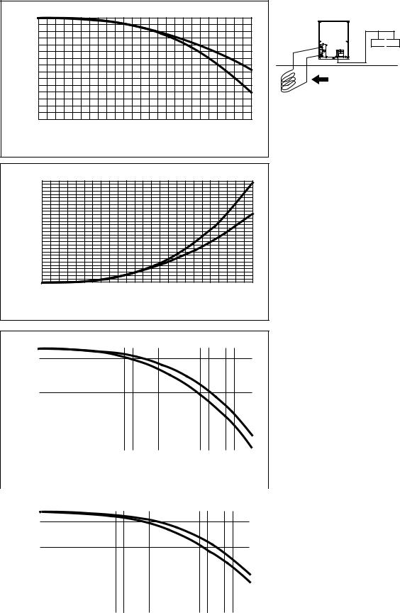
3.Pressure drop correction by brine concentration (For heat source unit)
Also, water pump is selected by the ratio of pressure drop of depending on the brine concentration.
Cooling
Ratio of pressure drop
8.0 |
|
|
|
|
|
|
|
|
|
|
|
|
|
|
Inlet-water temp. [°C] |
|||||||
7.0 |
|
|
|
Ethylene |
Glycol |
(cooling) |
|
|
|
|
|
|
|
|
|
|
|
|
|
|
|
|
|
|
|
|
|
|
|
|
|
|
|
|
|
|
|
|
|
|
|
|
|
|
|
|
|
|
|
|
|
|
|
|
|
|
|
|
|
|
|
|
|
|
|
|
|
|
6.0 |
|
|
|
|
|
|
|
|
|
|
|
|
|
|
|
|
|
|
|
|
|
|
|
|
|
|
|
|
|
|
|
|
|
|
|
|
|
|
|
|
|
|
|
|
|
|
|
|
|
|
|
|
|
|
|
|
|
|
|
|
|
|
|
|
|
|
|
|
|
|
|
|
|
|
|
|
|
|
|
|
|
|
|
|
|
|
|
|
|
|
|
|
|
|
|
|
|
|
|
|
|
|
|
|
|
|
|
|
|
|
|
|
|
|
5.0 |
|
|
|
|
|
|
|
|
|
|
|
|
|
|
|
|
|
|
|
|
|
|
|
|
|
|
|
|
|
|
|
|
|
|
|
|
|
|
|
|
|
|
|
|
|
|
|
|
|
|
|
|
|
|
|
|
|
|
|
|
|
|
|
|
|
|
|
|
|
|
|
|
|
|
|
|
|
|
|
|
|
|
|
|
|
|
|
|
|
|
|
|
|
|
|
|
|
|
|
|
|
|
|
|
|
|
|
|
|
|
|
|
|
|
4.0 |
|
|
|
|
|
|
|
|
|
|
|
|
|
|
|
|
|
|
|
|
|
-5°C |
|
|
|
|
|
|
|
|
|
|
|
|
|
|
|
|
|
|
|
|
|
||
|
|
|
|
|
|
|
|
|
|
|
|
|
|
|
|
|
|
|
|
|
||
|
|
|
|
|
|
|
|
|
|
|
|
|
|
|
|
|
|
|
|
|
||
|
|
|
|
|
|
|
|
|
|
|
|
|
|
|
|
|
|
|
|
|
||
|
|
|
|
|
|
|
|
|
|
|
|
|
|
|
|
|
|
|
|
|
|
|
3.0 |
|
|
|
|
|
|
|
|
|
|
|
|
|
|
|
|
|
|
|
|
|
0°C |
|
|
|
|
|
|
|
|
|
|
|
|
|
|
|
|
|
|
|
|
|
||
|
|
|
|
|
|
|
|
|
|
|
|
|
|
|
|
|
|
|
|
|
||
|
|
|
|
|
|
|
|
|
|
|
|
|
|
|
|
|
|
|
|
|
5°C |
|
|
|
|
|
|
|
|
|
|
|
|
|
|
|
|
|
|
|
|
|
|
|
|
|
|
|
|
|
|
|
|
|
|
|
|
|
|
|
|
|
|
|
|
|
|
|
2.0 |
|
|
|
|
|
|
|
|
|
|
|
|
|
|
|
|
|
|
|
|
|
10°C |
|
|
|
|
|
|
|
|
|
|
|
|
|
|
|
|
|
|
|
|
|
||
|
|
|
|
|
|
|
|
|
|
|
|
|
|
|
|
|
|
|
|
|
||
|
|
|
|
|
|
|
|
|
|
|
|
|
|
|
|
|
|
|
|
|
|
|
1.0 |
|
|
|
|
|
|
|
|
|
|
|
|
|
|
|
|
|
|
|
|
|
|
|
|
|
|
|
|
|
|
|
|
|
|
|
|
|
|
|
|
|
|
|
|
|
|
|
|
|
|
|
|
|
|
|
|
|
|
|
|
|
|
|
|
|
|
|
|
|
|
|
|
|
|
|
|
|
|
|
|
|
|
|
|
|
|
|
|
|
|
|
|
|
|
|
|
|
|
|
|
|
|
|
|
|
|
|
|
|
|
|
|
|
|
0% |
20% |
40% |
|
60% |
|
|
80% |
100% |
||||||||||||||
|
|
|
|
|
|
Brine concentration [wt%] |
|
|
|
|
|
|
|
|
||||||||
Ratio of pressure drop
8.0 |
|
|
|
|
|
|
|
|
|
|
|
|
|
|
Inlet-water temp. [°C] |
|||||||
7.0 |
|
|
|
Propylene |
|
Glycol |
|
(cooling) |
|
|
|
|
|
|
|
|
|
|
|
|
|
-5°C |
|
|
|
|
|
|
|
|
|
|
|
|
|
|
|
|
|
|
|
|
|
||
|
|
|
|
|
|
|
|
|
|
|
|
|
|
|
|
|
|
|
|
|
||
6.0 |
|
|
|
|
|
|
|
|
|
|
|
|
|
|
|
|
|
|
|
|
|
0°C |
|
|
|
|
|
|
|
|
|
|
|
|
|
|
|
|
|
|
|
|
|
||
|
|
|
|
|
|
|
|
|
|
|
|
|
|
|
|
|
|
|
|
|
||
|
|
|
|
|
|
|
|
|
|
|
|
|
|
|
|
|
|
|
|
|
||
|
|
|
|
|
|
|
|
|
|
|
|
|
|
|
|
|
|
|
|
|
5°C |
|
5.0 |
|
|
|
|
|
|
|
|
|
|
|
|
|
|
|
|
|
|
|
|
|
|
|
|
|
|
|
|
|
|
|
|
|
|
|
|
|
|
|
|
|
|
|
||
|
|
|
|
|
|
|
|
|
|
|
|
|
|
|
|
|
|
|
|
|
||
|
|
|
|
|
|
|
|
|
|
|
|
|
|
|
|
|
|
|
|
|
||
|
|
|
|
|
|
|
|
|
|
|
|
|
|
|
|
|
|
|
|
|
10°C |
|
4.0 |
|
|
|
|
|
|
|
|
|
|
|
|
|
|
|
|
|
|
|
|
|
|
|
|
|
|
|
|
|
|
|
|
|
|
|
|
|
|
|
|
|
|
|
||
|
|
|
|
|
|
|
|
|
|
|
|
|
|
|
|
|
|
|
|
|
||
|
|
|
|
|
|
|
|
|
|
|
|
|
|
|
|
|
|
|
|
|
|
|
|
|
|
|
|
|
|
|
|
|
|
|
|
|
|
|
|
|
|
|
|
|
|
3.0 |
|
|
|
|
|
|
|
|
|
|
|
|
|
|
|
|
|
|
|
|
|
|
|
|
|
|
|
|
|
|
|
|
|
|
|
|
|
|
|
|
|
|
|
|
|
|
|
|
|
|
|
|
|
|
|
|
|
|
|
|
|
|
|
|
|
|
|
|
|
|
|
|
|
|
|
|
|
|
|
|
|
|
|
|
|
|
|
|
|
|
|
|
|
|
|
|
|
|
|
|
|
|
|
|
|
|
|
|
|
|
|
|
|
|
2.0 |
|
|
|
|
|
|
|
|
|
|
|
|
|
|
|
|
|
|
|
|
|
|
|
|
|
|
|
|
|
|
|
|
|
|
|
|
|
|
|
|
|
|
|
|
|
|
|
|
|
|
|
|
|
|
|
|
|
|
|
|
|
|
|
|
|
|
|
|
|
|
|
|
|
|
|
|
|
|
|
|
|
|
|
|
|
|
|
|
|
|
|
|
|
|
|
|
|
|
|
|
|
|
|
|
|
|
|
|
|
|
|
|
|
|
1.0 |
|
|
|
|
|
|
|
|
|
|
|
|
|
|
|
|
|
|
|
|
|
|
|
|
|
|
|
|
|
|
|
|
|
|
|
|
|
|
|
|
|
|
|
|
|
|
|
|
|
|
|
|
|
|
|
|
|
|
|
|
|
|
|
|
|
|
|
|
|
|
|
|
|
|
|
|
|
|
|
|
|
|
|
|
|
|
|
|
|
|
|
|
|
|
|
|
|
|
|
|
|
|
|
|
|
|
|
|
|
|
|
|
|
|
0% |
20% |
40% |
60% |
80% |
100% |
Brine concentration [wt%]
Heating
Ratio of pressure drop
26.0 |
|
|
|
|
|
|
|
|
|
|
|
|
|
Inlet-water temp. [°C] |
|
|||||||
21.0 |
|
|
|
Ethylene |
|
Glycol |
(heating) |
|
|
|
|
|
|
|
|
|
|
|
|
|
|
|
|
|
|
|
|
|
|
|
|
|
|
|
|
|
|
|
|
|
|
|
|
|
|
|
|
|
|
|
|
|
|
|
|
|
|
|
|
|
|
|
|
|
|
|
|
|
|
|
|
|
|
|
|
|
|
|
|
|
|
|
|
|
|
|
|
|
|
|
|
16.0 |
|
|
|
|
|
|
|
|
|
|
|
|
|
|
|
|
|
|
|
|
|
|
|
|
|
|
|
|
|
|
|
|
|
|
|
|
|
|
|
|
|
|
|
|
|
|
|
|
|
|
|
|
|
|
|
|
|
|
|
|
|
|
|
|
|
|
|
|
|
|
|
|
|
|
|
|
|
|
|
|
|
|
|
|
|
|
|
|
|
|
|
|
|
|
|
|
|
|
|
|
|
|
|
|
|
|
|
|
|
|
|
|
|
|
11.0 |
|
|
|
|
|
|
|
|
|
|
|
|
|
|
|
|
|
|
|
|
-5°C |
|
|
|
|
|
|
|
|
|
|
|
|
|
|
|
|
|
|
|
|
|
|||
|
|
|
|
|
|
|
|
|
|
|
|
|
|
|
|
|
|
|
|
|||
|
|
|
|
|
|
|
|
|
|
|
|
|
|
|
|
|
|
|
|
|||
|
|
|
|
|
|
|
|
|
|
|
|
|
|
|
|
|
|
|
|
|||
|
|
|
|
|
|
|
|
|
|
|
|
|
|
|
|
|
|
|
|
|
||
6.0 |
|
|
|
|
|
|
|
|
|
|
|
|
|
|
|
|
|
|
|
|
0°C |
|
|
|
|
|
|
|
|
|
|
|
|
|
|
|
|
|
|
|
|
|
|||
|
|
|
|
|
|
|
|
|
|
|
|
|
|
|
|
|
|
|
|
|||
|
|
|
|
|
|
|
|
|
|
|
|
|
|
|
|
|
|
|
|
5°C |
||
|
|
|
|
|
|
|
|
|
|
|
|
|
|
|
|
|
|
|
|
|
||
1.0 |
|
|
|
|
|
|
|
|
|
|
|
|
|
|
|
|
|
|
|
|
10°C |
|
|
|
|
|
|
|
|
|
|
|
|
|
|
|
|
|
|
|
|
|
|||
|
|
|
|
|
|
|
|
|
|
|
|
|
|
|
|
|
|
|
|
|
|
|
|
|
|
|
|
|
|
|
|
|
|
|
|
|
|
|
|
|
|
|
|
|
|
0% 20% 40% 60% 80% 100%
Brine concentration [wt%]
Ratio of pressure drop
26.0 |
|
|
|
|
|
|
|
|
|
|
|
|
|
|
Inlet-water temp. [°C] |
|||||||
|
|
|
|
|
|
|
|
|
|
|
|
|
|
|||||||||
|
|
|
|
|
|
|
|
|
|
|
|
|
|
|
|
|
|
|
|
|
|
-5°C |
21.0 |
|
|
|
Propylene |
|
Glycol |
|
(heating) |
|
|
|
|
|
|
|
|
|
|
|
|
|
|
|
|
|
|
|
|
|
|
|
|
|
|
|
|
|
|
|
|
|
|
|
0°C |
|
|
|
|
|
|
|
|
|
|
|
|
|
|
|
|
|
|
|
|
|
|
||
16.0 |
|
|
|
|
|
|
|
|
|
|
|
|
|
|
|
|
|
|
|
|
|
|
|
|
|
|
|
|
|
|
|
|
|
|
|
|
|
|
|
|
|
|
|
||
|
|
|
|
|
|
|
|
|
|
|
|
|
|
|
|
|
|
|
|
|
||
|
|
|
|
|
|
|
|
|
|
|
|
|
|
|
|
|
|
|
|
|
||
|
|
|
|
|
|
|
|
|
|
|
|
|
|
|
|
|
|
|
|
|
5°C |
|
11.0 |
|
|
|
|
|
|
|
|
|
|
|
|
|
|
|
|
|
|
|
|
|
|
|
|
|
|
|
|
|
|
|
|
|
|
|
|
|
|
|
|
|
|
|
||
|
|
|
|
|
|
|
|
|
|
|
|
|
|
|
|
|
|
|
|
|
||
|
|
|
|
|
|
|
|
|
|
|
|
|
|
|
|
|
|
|
|
|
||
|
|
|
|
|
|
|
|
|
|
|
|
|
|
|
|
|
|
|
|
|
10°C |
|
|
|
|
|
|
|
|
|
|
|
|
|
|
|
|
|
|
|
|
|
|
||
6.0 |
|
|
|
|
|
|
|
|
|
|
|
|
|
|
|
|
|
|
|
|
|
|
|
|
|
|
|
|
|
|
|
|
|
|
|
|
|
|
|
|
|
|
|
||
|
|
|
|
|
|
|
|
|
|
|
|
|
|
|
|
|
|
|
|
|
|
|
|
|
|
|
|
|
|
|
|
|
|
|
|
|
|
|
|
|
|
|
|
|
|
|
|
|
|
|
|
|
|
|
|
|
|
|
|
|
|
|
|
|
|
|
|
|
|
|
|
|
|
|
|
|
|
|
|
|
|
|
|
|
|
|
|
|
|
|
|
1.0 |
|
|
|
|
|
|
|
|
|
|
|
|
|
|
|
|
|
|
|
|
|
|
|
|
|
|
|
|
|
|
|
|
|
|
|
|
|
|
|
|
|
|
|
|
|
|
|
|
|
|
|
|
|
|
|
|
|
|
|
|
|
|
|
|
|
|
|
|
|
|
|
|
|
|
|
|
|
|
|
|
|
|
|
|
|
|
|
|
|
|
|
|
|
|
|
|
|
|
|
|
|
|
|
|
|
|
|
|
|
|
|
|
|
|
0% |
20% |
40% |
|
60% |
|
|
80% |
100% |
||||||||||||||
Brine concentration [wt%]
* Please supply strainer on site.
- 3 -

II Heat source unit information
1.General lineup of water-cooled heat source unit
WY (Heat Pump) Series (8HP-36HP)
PQHY-P YHM-A
PQHY-P YSHM-A
Model |
8HP |
10HP |
12HP |
16HP |
|
|
|
|
|
Model Name |
PQHY-P200YHM-A |
PQHY-P250YHM-A |
PQHY-P300YHM-A |
PQHY-P400YSHM-A |
|
|
|
|
|
|
|
|
|
|
Model |
18HP |
20HP |
22HP |
24HP |
|
|
|
|
|
Model Name |
PQHY-P450YSHM-A |
PQHY-P500YSHM-A |
PQHY-P550YSHM-A |
PQHY-P600YSHM-A |
|
|
|
|
|
|
|
|
|
|
Model |
26HP |
28HP |
30HP |
32HP |
|
|
|
|
|
Model Name |
PQHY-P650YSHM-A |
PQHY-P700YSHM-A |
PQHY-P750YSHM-A |
PQHY-P800YSHM-A |
|
|
|
|
|
|
|
|
|
|
Model |
34HP |
36HP |
|
|
|
|
|
|
|
Model Name |
PQHY-P850YSHM-A |
PQHY-P900YSHM-A |
|
|
|
|
|
|
|
WR2 (Heat Recovery) Series (8HP-24HP)
PQRY-P YHM-A
PQRY-P YSHM-A
Model |
8HP |
10HP |
12HP |
16HP |
|
|
|
|
|
Model Name |
PQRY-P200YHM-A |
PQHRY-P250YHM-A |
PQRY-P300YHM-A |
PQRY-P400YSHM-A |
|
|
|
|
|
|
|
|
|
|
Model |
18HP |
20HP |
22HP |
24HP |
|
|
|
|
|
Model Name |
PQRY-P450YSHM-A |
PQRY-P500YSHM-A |
PQRY-P550YSHM-A |
PQRY-P600YSHM-A |
|
|
|
|
|
- 4 -

2.PQHY-P-Y(S)HM-A
(1)Specification
(1)-1 Heat source units specification for standard combination (Standard CITY MULTI indoor units, PWFY-P100/200VM-E-AU)
Model |
|
|
|
|
|
PQHY-P200YHM-A(For Ground source) |
Power source |
|
|
|
|
|
3-phase 4-wire 380-400-415V 50/60Hz |
Cooling capacity |
*1 |
kW |
22.4 |
|||
(Nominal) |
*1 |
kcal / h |
19,300 |
|||
|
*1 |
BTU / h |
76,400 |
|||
|
|
Power input |
kW |
3.92 |
||
|
|
Current input |
A |
6.6-6.2-6.0 |
||
|
|
COP |
kW / kW |
5.71 |
||
Temp. range of |
|
Indoor |
W.B. |
|
15.0~24.0°C(59~75°F) |
|
cooling |
|
Circulating water |
°C |
|
-5.0~45.0°C(23~113°F) |
|
Heating capacity |
|
*2 |
kW |
25.0 |
||
(Nominal) |
*2 |
kcal / h |
21,500 |
|||
|
*2 |
BTU / h |
85,300 |
|||
|
|
Power input |
kW |
4.12 |
||
|
|
Current input |
A |
6.9-6.6-6.3 |
||
|
|
COP |
kW / kW |
6.06 |
||
Temp. range of |
|
Indoor |
D.B. |
|
|
15.0~27.0°C(59~81°F) |
heating |
|
Circulating water |
°C |
|
-5.0~45.0°C(23~113°F) |
|
Indoor unit |
|
Total capacity |
|
|
|
50~130 % of heat source unit capacity |
connectable |
|
Model / Quantity |
|
|
|
P15~P250 / 1~17 |
Sound pressure level (measured in anechoic room) |
dB <A> |
47 |
||||
Refrigerant |
|
Liquid pipe |
mm(in.) |
|
9.52(3/8) Brazed |
|
piping diameter |
|
Gas pipe |
mm(in.) |
|
19.05(3/4) Brazed |
|
Circulating |
|
Water flow rate |
m3 / h |
5.76 |
||
water |
|
|
L/min |
96 |
||
|
|
|
cfm |
3.4 |
||
|
|
Pressure drop |
kPa |
|
17 |
|
|
|
Operating volume range |
m3 / h |
|
4.5 ~ 7.2 |
|
Compressor |
|
Type x Quantity |
|
|
|
Inverter scroll hermetic compressor |
|
|
Manufacture |
|
|
|
AC&R Works, MITSUBISHI ELECTRIC CORPORATION |
|
|
Starting method |
|
|
|
Inverter |
|
|
Motor output |
kW |
|
4.6 |
|
|
|
Case heater |
kW |
|
0.035(240 V) |
|
|
|
Lubricant |
|
|
|
MEL32 |
External finish |
|
|
|
|
|
Acrylic painted steel plate |
External dimension HxWxD |
mm |
|
1,160(1,100 without legs) x 880 x 550 |
|||
|
|
|
in. |
|
45-11/16(43-5/16 without legs) x 34-11/16 x 21-11/16 |
|
Protection |
|
High pressure protection |
|
High pressure sensor, High pressure switch at 4.15MPa (601 psi) |
||
devices |
|
Inverter circuit (COMP.) |
|
Over-heat protection, Over-current protection |
||
|
|
Compressor |
|
|
|
Over-heat protection |
Refrigerant |
|
Type x original charge |
|
R410A x 5.0kg (12lbs) |
||
|
|
Control |
|
|
|
Indoor LEV and BC controller |
Net weight |
|
|
kg(lbs) |
195(430) |
||
Heat exchanger |
|
|
|
|
|
plate type |
|
|
Water volume in plate |
l |
|
5.0 |
|
|
|
Water pressure Max. |
MPa |
|
1.0 |
|
HIC circuit (HIC: Heat Inter-Changer) |
- |
|||||
Drawing |
|
External |
|
|
|
KB94T222 |
|
|
Wiring |
|
|
|
KE94C317 |
Standard attachment |
Document |
|
|
|
Installation Manual |
|
|
|
Accessory |
|
|
|
Refrigerant conn. pipe |
Optional parts |
|
|
|
|
|
Joint: CMY-Y102S-G2 |
|
|
|
|
|
|
Header: CMY-Y104/108/1010-G |
Remarks
●Turn DipSW 3-9 ON before power ON.
●Details on foundation work, duct work, insulation work, electrical wiring, power source switch, and other items shall be referred to the Installation Manual. ●Due to continuing improvement, above specifications may be subject to change without notice.
●The ambient temperature of the heat source unit needs to be kept below 40°C D.B. ●The ambient relative humidity of the heat source unit needs to be kept below 80%. ●The heat source unit should not be installed at outdoor.
●Be sure to mount a strainer (more than 50 meshes) at the water inlet piping of the unit. ●Be sure to provide interlocking for the unit operation and water circuit.
●Add brine to circulating water when a unit is operating at water temperature below 10°C.
Notes: |
|
|
Unit converter |
1.<Standard CITY MULTI indoor unit> |
Nominal heating conditions(subject to JIS B8615-1) |
kcal |
=kW x 860 |
Nominal cooling conditions(subject to JIS B8615-1) |
BTU/h =kW x 3,412 |
||
Indoor:27°CDB/19°CWB(81°FDB/66°FWB) |
Indoor:20°CDB(68°FDB) |
cfm |
=m3/min x 35.31 |
Water temperature:30°C(86°F) |
Water temperature:20°C(68°F) |
||
Pipe length:7.5m(24-9/16ft.), Level difference:0m(0ft.) |
Pipe length:7.5m(24-9/16ft.), Level difference:0m(0ft.) |
lb |
=kg / 0.4536 |
Brine concentration 0% |
Brine concentration 0% |
|
|
2.<PWFY-P100/200VM-E-AU> |
Nominal heating conditions |
|
|
Nominal cooling conditions |
|
|
|
Circulating water Temp. : 30°C (86°F) |
Circulating water Temp. : 20°C (68°F) |
|
|
Pipe length : 7.5 m (24-9/16 ft) |
Pipe length : 7.5 m (24-9/16 ft) |
|
|
Level difference : 0m (0ft) |
Level difference : 0m (0ft) |
|
|
Inlet water Temp 23°C |
Inlet water Temp 30°C |
*The specification data is |
|
Water flow rate : 1.93m3/h (P100) / 3.86m3/h (P200) |
Water flow rate : 2.15m3/h (P100) / 4.30m3/h (P200) |
||
Brine concentration 0% |
Brine concentration 0% |
subject to rounding variation. |
|
- 5 -

Model |
|
|
PQHY-P250YHM-A(For Ground source) |
Power source |
|
|
3-phase 4-wire 380-400-415V 50/60Hz |
Cooling capacity |
*1 |
kW |
28.0 |
(Nominal) |
*1 |
kcal / h |
24,100 |
|
*1 |
BTU / h |
95,500 |
|
Power input |
kW |
5.45 |
|
Current input |
A |
9.2-8.7-8.4 |
|
COP |
kW / kW |
5.13 |
Temp. range of |
Indoor |
W.B. |
15.0~24.0°C(59~75°F) |
cooling |
Circulating water |
°C |
-5.0~45.0°C(23~113°F) |
Heating capacity |
*2 |
kW |
31.5 |
(Nominal) |
*2 |
kcal / h |
27,100 |
|
*2 |
BTU / h |
107,500 |
|
Power input |
kW |
5.80 |
|
Current input |
A |
9.7-9.3-8.9 |
|
COP |
kW / kW |
5.43 |
Temp. range of |
Indoor |
D.B. |
15.0~27.0°C(59~81°F) |
heating |
Circulating water |
°C |
-5.0~45.0°C(23~113°F) |
Indoor unit |
Total capacity |
|
50~130 % of heat source unit capacity |
connectable |
Model / Quantity |
|
P15~P250 / 1~21 |
Sound pressure level (measured in anechoic room) |
dB <A> |
49 |
|
Refrigerant |
Liquid pipe |
mm(in.) |
9.52(3/8) Brazed (12.7(1/2) Brazed,total length >= 90m) |
piping diameter |
Gas pipe |
mm(in.) |
22.2(7/8) Brazed |
Circulating |
Water flow rate |
m3 / h |
5.76 |
water |
|
L/min |
96 |
|
|
cfm |
3.4 |
|
Pressure drop |
kPa |
17 |
|
Operating volume range |
m3 / h |
4.5 ~ 7.2 |
Compressor |
Type x Quantity |
|
Inverter scroll hermetic compressor |
|
Manufacture |
|
AC&R Works, MITSUBISHI ELECTRIC CORPORATION |
|
Starting method |
|
Inverter |
|
Motor output |
kW |
6.3 |
|
Case heater |
kW |
0.035(240 V) |
|
Lubricant |
|
MEL32 |
External finish |
|
|
Acrylic painted steel plate |
External dimension HxWxD |
mm |
1,160(1,100 without legs) x 880 x 550 |
|
|
|
in. |
45-11/16(43-5/16 without legs) x 34-11/16 x 21-11/16 |
Protection |
High pressure |
protection |
High pressure sensor, High pressure switch at 4.15MPa (601 psi) |
devices |
Inverter circuit (COMP.) |
Over-heat protection, Over-current protection |
|
|
Compressor |
|
Over-heat protection |
Refrigerant |
Type x original charge |
R410A x 5.0kg (12lbs) |
|
|
Control |
|
Indoor LEV and BC controller |
Net weight |
|
kg(lbs) |
195(430) |
Heat exchanger |
|
|
plate type |
|
Water volume in plate |
l |
5.0 |
|
Water pressure Max. |
MPa |
1.0 |
HIC circuit (HIC: Heat |
Inter-Changer) |
|
- |
Drawing |
External |
|
KB94T222 |
|
Wiring |
|
KE94C317 |
Standard attachment |
Document |
|
Installation Manual |
|
Accessory |
|
Refrigerant conn. pipe |
Optional parts |
|
|
Joint: CMY-Y102S-G2, CMY-Y102L-G2 |
|
|
|
Header: CMY-Y104/108/1010-G |
Remarks
●Turn DipSW 3-9 ON before power ON.
●Details on foundation work, duct work, insulation work, electrical wiring, power source switch, and other items shall be referred to the Installation Manual. ●Due to continuing improvement, above specifications may be subject to change without notice.
●The ambient temperature of the heat source unit needs to be kept below 40°C D.B. ●The ambient relative humidity of the heat source unit needs to be kept below 80%. ●The heat source unit should not be installed at outdoor.
●Be sure to mount a strainer (more than 50 meshes) at the water inlet piping of the unit. ●Be sure to provide interlocking for the unit operation and water circuit.
●Add brine to circulating water when a unit is operating at water temperature below 10°C.
Notes: |
|
|
Unit converter |
1.<Standard CITY MULTI indoor unit> |
|
kcal |
=kW x 860 |
Nominal cooling conditions(subject to JIS B8615-1) |
Nominal heating conditions(subject to JIS B8615-1) |
BTU/h =kW x 3,412 |
|
Indoor:27°CDB/19°CWB(81°FDB/66°FWB) |
Indoor:20°CDB(68°FDB) |
cfm |
=m3/min x 35.31 |
Water temperature:30°C(86°F) |
Water temperature:20°C(68°F) |
||
Pipe length:7.5m(24-9/16ft.), Level difference:0m(0ft.) |
Pipe length:7.5m(24-9/16ft.), Level difference:0m(0ft.) |
lb |
=kg / 0.4536 |
Brine concentration 0% |
Brine concentration 0% |
|
|
2.<PWFY-P100/200VM-E-AU> |
Nominal heating conditions |
|
|
Nominal cooling conditions |
|
|
|
Circulating water Temp. : 30°C (86°F) |
Circulating water Temp. : 20°C (68°F) |
|
|
Pipe length : 7.5 m (24-9/16 ft) |
Pipe length : 7.5 m (24-9/16 ft) |
|
|
Level difference : 0m (0ft) |
Level difference : 0m (0ft) |
|
|
Inlet water Temp 23°C |
Inlet water Temp 30°C |
*The specification data is |
|
Water flow rate : 1.93m3/h (P100) / 3.86m3/h (P200) |
Water flow rate : 2.15m3/h (P100) / 4.30m3/h (P200) |
||
Brine concentration 0% |
Brine concentration 0% |
subject to rounding variation. |
|
- 6 -
Model |
|
|
PQHY-P300YHM-A(For Ground source) |
|||
Power source |
|
|
3-phase 4-wire 380-400-415V 50/60Hz |
|||
Cooling capacity |
*1 |
kW |
33.5 |
|
|
|
(Nominal) |
*1 |
kcal / h |
28,800 |
|
|
|
|
*1 |
BTU / h |
114,300 |
|
|
|
|
Power input |
kW |
7.36 |
|
|
|
|
Current input |
A |
12.4-11.8-11.3 |
|
|
|
|
COP |
kW / kW |
4.55 |
|
|
|
Temp. range of |
Indoor |
W.B. |
15.0~24.0°C(59~75°F) |
|
||
cooling |
Circulating water |
°C |
-5.0~45.0°C(23~113°F) |
|
||
Heating capacity |
*2 |
kW |
37.5 |
|
|
|
(Nominal) |
*2 |
kcal / h |
32,300 |
|
|
|
|
*2 |
BTU / h |
128,000 |
|
|
|
|
Power input |
kW |
8.15 |
|
|
|
|
Current input |
A |
13.7-13.0-12.5 |
|
|
|
|
COP |
kW / kW |
4.60 |
|
|
|
Temp. range of |
Indoor |
D.B. |
15.0~27.0°C(59~81°F) |
|||
heating |
Circulating water |
°C |
-5.0~45.0°C(23~113°F) |
|||
Indoor unit |
Total capacity |
|
50~130 % of heat source unit capacity |
|||
connectable |
Model / Quantity |
|
P15~P250 / 1~26 |
|||
Sound pressure level (measured in anechoic room) |
dB <A> |
50 |
|
|
|
|
Refrigerant |
Liquid pipe |
mm(in.) |
9.52(3/8) Brazed (12.7(1/2) Brazed,total length >= 40m) |
|||
piping diameter |
Gas pipe |
mm(in.) |
22.2(7/8) Brazed |
|
||
Circulating |
Water flow rate |
m3 / h |
5.76 |
|
|
|
water |
|
L/min |
96 |
|
|
|
|
|
cfm |
3.4 |
|
|
|
|
Pressure drop |
kPa |
17 |
|
|
|
|
Operating volume range |
m3 / h |
4.5 ~ 7.2 |
|
|
|
Compressor |
Type x Quantity |
|
Inverter scroll hermetic compressor |
|
||
|
Manufacture |
|
AC&R Works, MITSUBISHI ELECTRIC CORPORATION |
|
||
|
Starting method |
|
Inverter |
|
||
|
Motor output |
kW |
7.4 |
|
|
|
|
Case heater |
kW |
0.035(240 V) |
|
||
|
Lubricant |
|
MEL32 |
|
||
External finish |
|
|
Acrylic painted steel plate |
|
||
External dimension HxWxD |
mm |
1,160(1,100 without legs) x 880 x 550 |
|
|||
|
|
in. |
45-11/16(43-5/16 without legs) x 34-11/16 x 21-11/16 |
|||
Protection |
High pressure |
protection |
High pressure sensor, High pressure switch at 4.15MPa (601 psi) |
|
||
devices |
Inverter circuit (COMP.) |
Over-heat protection, Over-current protection |
|
|||
|
Compressor |
|
Over-heat protection |
|
||
Refrigerant |
Type x original charge |
R410A x 5.0kg (12lbs) |
|
|||
|
Control |
|
Indoor LEV and BC controller |
|
||
Net weight |
|
kg(lbs) |
195(430) |
|
|
|
Heat exchanger |
|
|
plate type |
|
||
|
Water volume in plate |
l |
5.0 |
|
|
|
|
Water pressure Max. |
MPa |
1.0 |
|
|
|
HIC circuit (HIC: Heat |
Inter-Changer) |
|
- |
|
|
|
Drawing |
External |
|
KB94T222 |
|||
|
Wiring |
|
KE94C317 |
|||
Standard attachment |
Document |
|
Installation Manual |
|||
|
Accessory |
|
Refrigerant conn. pipe |
|||
Optional parts |
|
|
Joint: CMY-Y102S-G2,CMY-Y102L-G2 |
|||
|
|
|
Header: CMY-Y104/108/1010-G |
|||
Remarks
●Turn DipSW 3-9 ON before power ON.
●Details on foundation work, duct work, insulation work, electrical wiring, power source switch, and other items shall be referred to the Installation Manual. ●Due to continuing improvement, above specifications may be subject to change without notice.
●The ambient temperature of the heat source unit needs to be kept below 40°C D.B. ●The ambient relative humidity of the heat source unit needs to be kept below 80%. ●The heat source unit should not be installed at outdoor.
●Be sure to mount a strainer (more than 50 meshes) at the water inlet piping of the unit. ●Be sure to provide interlocking for the unit operation and water circuit.
●Add brine to circulating water when a unit is operating at water temperature below 10°C.
Notes: |
|
|
Unit converter |
1.<Standard CITY MULTI indoor unit> |
|
kcal |
=kW x 860 |
Nominal cooling conditions(subject to JIS B8615-1) |
Nominal heating conditions(subject to JIS B8615-1) |
BTU/h =kW x 3,412 |
|
Indoor:27°CDB/19°CWB(81°FDB/66°FWB) |
Indoor:20°CDB(68°FDB) |
cfm |
=m3/min x 35.31 |
Water temperature:30°C(86°F) |
Water temperature:20°C(68°F) |
||
Pipe length:7.5m(24-9/16ft.), Level difference:0m(0ft.) |
Pipe length:7.5m(24-9/16ft.), Level difference:0m(0ft.) |
lb |
=kg / 0.4536 |
Brine concentration 0% |
Brine concentration 0% |
|
|
2.<PWFY-P100/200VM-E-AU> |
Nominal heating conditions |
|
|
Nominal cooling conditions |
|
|
|
Circulating water Temp. : 30°C (86°F) |
Circulating water Temp. : 20°C (68°F) |
|
|
Pipe length : 7.5 m (24-9/16 ft) |
Pipe length : 7.5 m (24-9/16 ft) |
|
|
Level difference : 0m (0ft) |
Level difference : 0m (0ft) |
|
|
Inlet water Temp 23°C |
Inlet water Temp 30°C |
*The specification data is |
|
Water flow rate : 1.93m3/h (P100) / 3.86m3/h (P200) |
Water flow rate : 2.15m3/h (P100) / 4.30m3/h (P200) |
||
Brine concentration 0% |
Brine concentration 0% |
subject to rounding variation. |
|
- 7 -

Model |
|
|
PQHY-P400YSHM-A (For Ground source) |
||
Power source |
|
|
3-phase 4-wire 380-400-415V 50/60Hz |
||
Cooling capacity |
*1 |
kW |
45.0 |
||
(Nominal) |
*1 |
kcal / h |
38,700 |
||
|
*1 |
BTU / h |
153,500 |
||
|
Power input |
kW |
8.25 |
||
|
Current input |
A |
13.9-13.2-12.7 |
||
|
COP |
kW / kW |
5.45 |
||
Temp. range of |
Indoor |
W.B. |
15.0~24.0°C(59~75°F) |
||
cooling |
Circulating water |
°C |
-5.0~45.0°C(23~113°F) |
||
Heating capacity |
*2 |
kW |
50.0 |
||
(Nominal) |
*2 |
kcal / h |
43,000 |
||
|
*2 |
BTU / h |
170,600 |
||
|
Power input |
kW |
8.65 |
||
|
Current input |
A |
14.6-13.8-13.3 |
||
|
COP |
kW / kW |
5.78 |
||
Temp. range of |
Indoor |
D.B. |
15.0~27.0°C(59~81°F) |
||
heating |
Circulating water |
°C |
-5.0~45.0°C(23~113°F) |
||
Indoor unit |
Total capacity |
|
50~130 % of heat source unit capacity |
||
connectable |
Model / Quantity |
|
P15~P250 / 1~34 |
||
Sound pressure level (measured in anechoic room) |
dB <A> |
|
50 |
||
Refrigerant |
Liquid pipe |
mm(in.) |
12.7(1/2) Brazed |
||
piping diameter |
Gas pipe |
mm(in.) |
28.58(1-1/8) Brazed |
||
Set Model |
|
|
|
|
|
Model |
|
|
PQHY-P200YHM-A(For Ground source) |
|
PQHY-P200YHM-A(For Ground source) |
Circulating |
Water flow rate |
m3 / h |
5.76 + |
5.76 |
|
water |
|
L/min |
96 + 96 |
||
|
|
cfm |
3.4 + 3.4 |
||
|
Pressure drop |
kPa |
17 |
|
17 |
|
Operating volume range |
m3 / h |
4.5 + 4.5 ~ |
7.2 + 7.2 |
|
Compressor |
Type x Quantity |
|
Inverter scroll hermetic compressor |
|
Inverter scroll hermetic compressor |
|
Manufacture |
|
AC&R Works, MITSUBISHI ELECTRIC CORPORATION |
|
AC&R Works, MITSUBISHI ELECTRIC CORPORATION |
|
Starting method |
|
Inverter |
|
Inverter |
|
Motor output |
kW |
4.6 |
|
4.6 |
|
Case heater |
kW |
0.035(240 V) |
|
0.035(240 V) |
|
Lubricant |
|
MEL32 |
|
MEL32 |
External finish |
|
|
Acrylic painted steel plate |
|
Acrylic painted steel plate |
External dimension HxWxD |
mm |
1,160(1,100 without legs) x 880 x 550 |
|
1,160(1,100 without legs) x 880 x 550 |
|
|
|
in. |
45-11/16(43-5/16 without legs) x 34-11/16 x 21-11/16 |
|
45-11/16(43-5/16 without legs) x 34-11/16 x 21-11/16 |
Protection |
High pressure |
protection |
High pressure sensor, High pressure switch at 4.15MPa (601 psi) |
|
High pressure sensor, High pressure switch at 4.15MPa (601 psi) |
devices |
Inverter circuit (COMP.) |
Over-heat protection, Over-current protection |
|
Over-heat protection, Over-current protection |
|
|
Compressor |
|
Over-heat protection |
|
Over-heat protection |
Refrigerant |
Type x original charge |
R410A x 5.0kg (12lbs) |
|
R410A x 5.0kg (12lbs) |
|
|
Control |
|
Indoor LEV and |
BC controller |
|
Net weight |
|
kg(lbs) |
195(430) |
|
195(430) |
Heat exchanger |
|
|
plate type |
|
plate type |
|
Water volume in plate |
l |
5.0 |
|
5.0 |
|
Water pressure Max. |
MPa |
1.0 |
|
1.0 |
HIC circuit (HIC: Heat |
Inter-Changer) |
|
- |
|
- |
Pipe between unit and |
Liquid pipe |
mm(in.) |
9.52(3/8) Brazed |
|
9.52(3/8) Brazed |
distributor |
Gas pipe |
mm(in.) |
19.05(3/ 4) Brazed |
|
19.05(3/ 4) Brazed |
Drawing |
External |
|
KB94T223 |
||
|
Wiring |
|
KE94C317 |
|
KE94C317 |
Standard attachment |
Document |
|
Installation |
Manual |
|
|
Accessory |
|
Refrigerant conn. pipe |
||
Optional parts |
|
|
Heat Source Twinning kit: CMY-Y100VBK2 |
||
|
|
|
Joint: CMY-Y102S-G2, CMY-Y102L-G2, CMY-Y202-G2 |
||
|
|
|
Header: CMY-Y104/108/1010-G |
||
Remarks |
|
|
|
|
|
●Turn DipSW 3-9 ON before power ON.
●Details on foundation work, duct work, insulation work, electrical wiring, power source switch, and other items shall be referred to the Installation Manual. ●Due to continuing improvement, above specifications may be subject to change without notice.
●The ambient temperature of the heat source unit needs to be kept below 40°C D.B. ●The ambient relative humidity of the heat source unit needs to be kept below 80%. ●The heat source unit should not be installed at outdoor.
●Be sure to mount a strainer (more than 50 meshes) at the water inlet piping of the unit. ●Be sure to provide interlocking for the unit operation and water circuit.
●Add brine to circulating water when a unit is operating at water temperature below 10°C. ●Twinning kit is required.
Notes: |
|
|
Unit converter |
|
1.<Standard CITY MULTI indoor unit> |
|
kcal |
=kW x 860 |
|
Nominal cooling conditions(subject to JIS B8615-1) |
Nominal heating conditions(subject to JIS B8615-1) |
BTU/h |
=kW x 3,412 |
|
Indoor:27°CDB/19°CWB(81°FDB/66°FWB) |
Indoor:20°CDB(68°FDB) |
cfm |
=m3/min x 35.31 |
|
Water temperature:30°C(86°F) |
Water temperature:20°C(68°F) |
|||
Pipe length:7.5m(24-9/16ft.), Level difference:0m(0ft.) |
Pipe length:7.5m(24-9/16ft.), Level difference:0m(0ft.) |
lb |
=kg / 0.4536 |
|
Brine concentration 0% |
Brine concentration 0% |
|
|
|
2.<PWFY-P100/200VM-E-AU> |
Nominal heating conditions |
|
|
|
Nominal cooling conditions |
|
|
||
Circulating water Temp. : 30°C (86°F) |
Circulating water Temp. : 20°C (68°F) |
|
|
|
Pipe length : 7.5 m (24-9/16 ft) |
Pipe length : 7.5 m (24-9/16 ft) |
|
|
|
Level difference : 0m (0ft) |
Level difference : 0m (0ft) |
|
|
|
Inlet water Temp 23°C |
Inlet water Temp 30°C |
*The specification data is |
||
Water flow rate : 1.93m3/h (P100) / 3.86m3/h (P200) |
Water flow rate : 2.15m3/h (P100) / 4.30m3/h (P200) |
|||
subject to rounding variation. |
||||
Brine concentration 0% |
Brine concentration 0% |
|||
|
|
|||
- 8 -

Model |
|
|
PQHY-P450YSHM-A(For Ground source) |
|
Power source |
|
|
3-phase 4-wire 380-400-415V 50/60Hz |
|
Cooling capacity |
*1 |
kW |
50.0 |
|
(Nominal) |
*1 |
kcal / h |
43,000 |
|
|
*1 |
BTU / h |
170,600 |
|
|
Power input |
kW |
9.84 |
|
|
Current input |
A |
16.6-15.7-15.2 |
|
|
COP |
kW / kW |
5.08 |
|
Temp. range of |
Indoor |
W.B. |
15.0~24.0°C(59~75°F) |
|
cooling |
Circulating water |
°C |
-5.0~45.0°C(23~113°F) |
|
Heating capacity |
*2 |
kW |
56.0 |
|
(Nominal) |
*2 |
kcal / h |
48,200 |
|
|
*2 |
BTU / h |
191,100 |
|
|
Power input |
kW |
10.42 |
|
|
Current input |
A |
17.5-16.7-16.1 |
|
|
COP |
kW / kW |
5.37 |
|
Temp. range of |
Indoor |
D.B. |
15.0~27.0°C(59~81°F) |
|
heating |
Circulating water |
°C |
-5.0~45.0°C(23~113°F) |
|
Indoor unit |
Total capacity |
|
50~130 % of heat source unit capacity |
|
connectable |
Model / Quantity |
|
P15~P250 / 1~39 |
|
Sound pressure level (measured in anechoic room) |
dB <A> |
51 |
||
Refrigerant |
Liquid pipe |
mm(in.) |
15.88(5/8) Brazed |
|
piping diameter |
Gas pipe |
mm(in.) |
28.58(1-1/8) Brazed |
|
Set Model |
|
|
|
|
Model |
|
|
PQHY-P250YHM-A(For Ground source) |
PQHY-P200YHM-A(For Ground source) |
Circulating |
Water flow rate |
m3 / h |
5.76 + 5.76 |
|
water |
|
L/min |
96 + 96 |
|
|
|
cfm |
3.4 + 3.4 |
|
|
Pressure drop |
kPa |
17 |
17 |
|
Operating volume range |
m3 / h |
4.5 + 4.5 ~ 7.2 + 7.2 |
|
Compressor |
Type x Quantity |
|
Inverter scroll hermetic compressor |
Inverter scroll hermetic compressor |
|
Manufacture |
|
AC&R Works, MITSUBISHI ELECTRIC CORPORATION |
AC&R Works, MITSUBISHI ELECTRIC CORPORATION |
|
Starting method |
|
Inverter |
Inverter |
|
Motor output |
kW |
6.3 |
4.6 |
|
Case heater |
kW |
0.035(240 V) |
0.035(240 V) |
|
Lubricant |
|
MEL32 |
MEL32 |
External finish |
|
|
Acrylic painted steel plate |
Acrylic painted steel plate |
External dimension HxWxD |
mm |
1,160(1,100 without legs) x 880 x 550 |
1,160(1,100 without legs) x 880 x 550 |
|
|
|
in. |
45-11/16(43-5/16 without legs) x 34-11/16 x 21-11/16 |
45-11/16(43-5/16 without legs) x 34-11/16 x 21-11/16 |
Protection |
High pressure |
protection |
High pressure sensor, High pressure switch at 4.15MPa (601 psi) |
High pressure sensor, High pressure switch at 4.15MPa (601 psi) |
devices |
Inverter circuit (COMP.) |
Over-heat protection, Over-current protection |
Over-heat protection, Over-current protection |
|
|
Compressor |
|
Over-heat protection |
Over-heat protection |
Refrigerant |
Type x original charge |
R410A x 5.0kg (12lbs) |
R410A x 5.0kg (12lbs) |
|
|
Control |
|
Indoor LEV and BC controller |
|
Net weight |
|
kg(lbs) |
195(430) |
195(430) |
Heat exchanger |
|
|
plate type |
plate type |
|
Water volume in plate |
l |
5.0 |
5.0 |
|
Water pressure Max. |
MPa |
1.0 |
1.0 |
HIC circuit (HIC: Heat Inter-Changer) |
|
- |
- |
|
Pipe between unit and |
Liquid pipe |
mm(in.) |
9.52(3/8) Brazed |
9.52(3/8) Brazed |
distributor |
Gas pipe |
mm(in.) |
22.2(7/ 8) Brazed |
22.2(7/ 8) Brazed |
Drawing |
External |
|
KB94T223 |
|
|
Wiring |
|
KE94C317 |
KE94C317 |
Standard attachment |
Document |
|
Installation |
Manual |
|
Accessory |
|
Refrigerant conn. pipe |
|
Optional parts |
|
|
Heat Source Twinning kit: CMY-Y100VBK2 |
|
|
|
|
Joint: CMY-Y102S-G2, CMY-Y102L-G2, CMY-Y202-G2 |
|
|
|
|
Header: CMY-Y104/108/1010-G |
|
Remarks
●Turn DipSW 3-9 ON before power ON.
●Details on foundation work, duct work, insulation work, electrical wiring, power source switch, and other items shall be referred to the Installation Manual. ●Due to continuing improvement, above specifications may be subject to change without notice.
●The ambient temperature of the heat source unit needs to be kept below 40 °C D.B. ●The ambient relative humidity of the heat source unit needs to be kept below 80%. ●The heat source unit should not be installed at outdoor.
●Be sure to mount a strainer (more than 50 meshes) at the water inlet piping of the unit. ●Be sure to provide interlocking for the unit operation and water circuit.
●Add brine to circulating water when a unit is operating at water temperature below 10°C. ●Twinning kit is required.
Notes: |
|
|
Unit converter |
1.<Standard CITY MULTI indoor unit> |
|
kcal |
=kW x 860 |
Nominal cooling conditions(subject to JIS B8615-1) |
Nominal heating conditions(subject to JIS B8615-1) |
BTU/h |
=kW x 3,412 |
Indoor:27°CDB/19°CWB(81°FDB/66°FWB) |
Indoor:20°CDB(68°FDB) |
cfm |
=m3/min x 35.31 |
Water temperature:30°C(86°F) |
Water temperature:20°C(68°F) |
||
Pipe length:7.5m(24-9/16ft.), Level difference:0m(0ft.) |
Pipe length:7.5m(24-9/16ft.), Level difference:0m(0ft.) |
lb |
=kg / 0.4536 |
Brine concentration 0% |
Brine concentration 0% |
|
|
2.<PWFY-P100/200VM-E-AU> |
|
|
|
Nominal cooling conditions |
Nominal heating conditions |
|
|
Circulating water Temp. : 30°C (86°F) |
Circulating water Temp. : 20°C (68°F) |
|
|
Pipe length : 7.5 m (24-9/16 ft) |
Pipe length : 7.5 m (24-9/16 ft) |
|
|
Level difference : 0m (0ft) |
Level difference : 0m (0ft) |
|
|
Inlet water Temp 23°C |
Inlet water Temp 30°C |
*The specification data is |
|
Water flow rate : 1.93m3/h (P100) / 3.86m3/h (P200) |
Water flow rate : 2.15m3/h (P100) / 4.30m3/h (P200) |
||
Brine concentration 0% |
Brine concentration 0% |
subject to rounding variation. |
|
- 9 -

Model |
|
|
PQHY-P500YSHM-A(For Ground source) |
|
Power source |
|
|
3-phase 4-wire 380-400-415V 50/60Hz |
|
Cooling capacity |
*1 |
kW |
56.0 |
|
(Nominal) |
*1 |
kcal / h |
48,200 |
|
|
*1 |
BTU / h |
191,100 |
|
|
Power input |
kW |
11.45 |
|
|
Current input |
A |
19.3-18.3-17.6 |
|
|
COP |
kW / kW |
4.89 |
|
Temp. range of |
Indoor |
W.B. |
15.0~24.0°C(59~75°F) |
|
cooling |
Circulating water |
°C |
-5.0~45.0°C(23~113°F) |
|
Heating capacity |
*2 |
kW |
63.0 |
|
(Nominal) |
*2 |
kcal / h |
54,200 |
|
|
*2 |
BTU / h |
215,000 |
|
|
Power input |
kW |
12.06 |
|
|
Current input |
A |
20.3-19.3-18.6 |
|
|
COP |
kW / kW |
5.22 |
|
Temp. range of |
Indoor |
D.B. |
15.0~27.0°C(59~81°F) |
|
heating |
Circulating water |
°C |
-5.0~45.0°C(23~113°F) |
|
Indoor unit |
Total capacity |
|
50~130 % of heat source unit capacity |
|
connectable |
Model / Quantity |
|
P15~P250 / 1~43 |
|
Sound pressure level (measured in anechoic room) |
dB <A> |
52 |
||
Refrigerant |
Liquid pipe |
mm(in.) |
15.88(5/8) Brazed |
|
piping diameter |
Gas pipe |
mm(in.) |
28.58(1-1/8) Brazed |
|
Set Model |
|
|
|
|
Model |
|
|
PQHY-P250YHM-A(For Ground source) |
PQHY-P250YHM-A(For Ground source) |
Circulating |
Water flow rate |
m3 / h |
5.76 + 5.76 |
|
water |
|
L/min |
96 + 96 |
|
|
|
cfm |
3.4 + 3.4 |
|
|
Pressure drop |
kPa |
17 |
17 |
|
Operating volume range |
m3 / h |
4.5 + 4.5 ~ 7.2 + 7.2 |
|
Compressor |
Type x Quantity |
|
Inverter scroll hermetic compressor |
Inverter scroll hermetic compressor |
|
Manufacture |
|
AC&R Works, MITSUBISHI ELECTRIC CORPORATION |
AC&R Works, MITSUBISHI ELECTRIC CORPORATION |
|
Starting method |
|
Inverter |
Inverter |
|
Motor output |
kW |
6.3 |
6.3 |
|
Case heater |
kW |
0.035(240 V) |
0.035(240 V) |
|
Lubricant |
|
MEL32 |
MEL32 |
External finish |
|
|
Acrylic painted steel plate |
Acrylic painted steel plate |
External dimension HxWxD |
mm |
1,160(1,100 without legs) x 880 x 550 |
1,160(1,100 without legs) x 880 x 550 |
|
|
|
in. |
45-11/16(43-5/16 without legs) x 34-11/16 x 21-11/16 |
45-11/16(43-5/16 without legs) x 34-11/16 x 21-11/16 |
Protection |
High pressure |
protection |
High pressure sensor, High pressure switch at 4.15MPa (601 psi) |
High pressure sensor, High pressure switch at 4.15MPa (601 psi) |
devices |
Inverter circuit (COMP.) |
Over-heat protection, Over-current protection |
Over-heat protection, Over-current protection |
|
|
Compressor |
|
Over-heat protection |
Over-heat protection |
Refrigerant |
Type x original charge |
R410A x 5.0kg (12lbs) |
R410A x 5.0kg (12lbs) |
|
|
Control |
|
Indoor LEV and BC controller |
|
Net weight |
|
kg(lbs) |
195(430) |
195(430) |
Heat exchanger |
|
|
plate type |
plate type |
|
Water volume in plate |
l |
5.0 |
5.0 |
|
Water pressure Max. |
MPa |
1.0 |
1.0 |
HIC circuit (HIC: Heat Inter-Changer) |
|
- |
- |
|
Pipe between unit and |
Liquid pipe |
mm(in.) |
9.52(3/8) Brazed |
9.52(3/8) Brazed |
distributor |
Gas pipe |
mm(in.) |
22.2(7/ 8) Brazed |
22.2(7/ 8) Brazed |
Drawing |
External |
|
KB94T223 |
|
|
Wiring |
|
KE94C317 |
KE94C317 |
Standard attachment |
Document |
|
Installation |
Manual |
|
Accessory |
|
Refrigerant conn. pipe |
|
Optional parts |
|
|
Heat Source Twinning kit: CMY-Y100VBK2 |
|
|
|
|
Joint: CMY-Y102S-G2, CMY-Y102L-G2, CMY-Y202-G2 |
|
|
|
|
Header: CMY-Y104/108/1010-G |
|
Remarks |
|
|
|
|
●Turn DipSW 3-9 ON before power ON.
●Details on foundation work, duct work, insulation work, electrical wiring, power source switch, and other items shall be referred to the Installation Manual. ●Due to continuing improvement, above specifications may be subject to change without notice.
●The ambient temperature of the heat source unit needs to be kept below 40°C D.B. ●The ambient relative humidity of the heat source unit needs to be kept below 80%. ●The heat source unit should not be installed at outdoor.
●Be sure to mount a strainer (more than 50 meshes) at the water inlet piping of the unit. ●Be sure to provide interlocking for the unit operation and water circuit.
●Add brine to circulating water when a unit is operating at water temperature below 10°C. ●Twinning kit is required.
Notes: |
|
|
Unit converter |
1.<Standard CITY MULTI indoor unit> |
|
kcal |
=kW x 860 |
Nominal cooling conditions(subject to JIS B8615-1) |
Nominal heating conditions(subject to JIS B8615-1) |
BTU/h |
=kW x 3,412 |
Indoor:27°CDB/19°CWB(81°FDB/66°FWB) |
Indoor:20°CDB(68°FDB) |
cfm |
=m3/min x 35.31 |
Water temperature:30°C(86°F) |
Water temperature:20°C(68°F) |
||
Pipe length:7.5m(24-9/16ft.), Level difference:0m(0ft.) |
Pipe length:7.5m(24-9/16ft.), Level difference:0m(0ft.) |
lb |
=kg / 0.4536 |
Brine concentration 0% |
Brine concentration 0% |
|
|
2.<PWFY-P100/200VM-E-AU> |
Nominal heating conditions |
|
|
Nominal cooling conditions |
|
|
|
Circulating water Temp. : 30°C (86°F) |
Circulating water Temp. : 20°C (68°F) |
|
|
Pipe length : 7.5 m (24-9/16 ft) |
Pipe length : 7.5 m (24-9/16 ft) |
|
|
Level difference : 0m (0ft) |
Level difference : 0m (0ft) |
|
|
Inlet water Temp 23°C |
Inlet water Temp 30°C |
*The specification data is |
|
Water flow rate : 1.93m3/h (P100) / 3.86m3/h (P200) |
Water flow rate : 2.15m3/h (P100) / 4.30m3/h (P200) |
||
Brine concentration 0% |
Brine concentration 0% |
subject to rounding variation. |
|
- 10 -

Model |
|
|
PQHY-P550YSHM-A(For Ground source) |
|
Power source |
|
|
3-phase 4-wire 380-400-415V 50/60Hz |
|
Cooling capacity |
*1 |
kW |
63.0 |
|
(Nominal) |
*1 |
kcal / h |
54,200 |
|
|
*1 |
BTU / h |
215,000 |
|
|
Power input |
kW |
13.46 |
|
|
Current input |
A |
22.7-21.5-20.8 |
|
|
COP |
kW / kW |
4.68 |
|
Temp. range of |
Indoor |
W.B. |
15.0~24.0°C(59~75°F) |
|
cooling |
Circulating water |
°C |
-5.0~45.0°C(23~113°F) |
|
Heating capacity |
*2 |
kW |
69.0 |
|
(Nominal) |
*2 |
kcal / h |
59,300 |
|
|
*2 |
BTU / h |
235,400 |
|
|
Power input |
kW |
14.65 |
|
|
Current input |
A |
24.7-23.4-22.6 |
|
|
COP |
kW / kW |
4.70 |
|
Temp. range of |
Indoor |
D.B. |
15.0~27.0°C(59~81°F) |
|
heating |
Circulating water |
°C |
-5.0~45.0°C(23~113°F) |
|
Indoor unit |
Total capacity |
|
50~130 % of heat source unit capacity |
|
connectable |
Model / Quantity |
|
P15~P250 / 2~47 |
|
Sound pressure level (measured in anechoic room) |
dB <A> |
52.5 |
||
Refrigerant |
Liquid pipe |
mm(in.) |
15.88(5/8) Brazed |
|
piping diameter |
Gas pipe |
mm(in.) |
28.58(1-1/8) Brazed |
|
Set Model |
|
|
|
|
Model |
|
|
PQHY-P300YHM-A(For Ground source) |
PQHY-P250YHM-A(For Ground source) |
Circulating |
Water flow rate |
m3 / h |
5.76 + 5.76 |
|
water |
|
L/min |
96 + 96 |
|
|
|
cfm |
3.4 + 3.4 |
|
|
Pressure drop |
kPa |
17 |
17 |
|
Operating volume range |
m3 / h |
4.5 + 4.5 |
~ 7.2 + 7.2 |
Compressor |
Type x Quantity |
|
Inverter scroll hermetic compressor |
Inverter scroll hermetic compressor |
|
Manufacture |
|
AC&R Works, MITSUBISHI ELECTRIC CORPORATION |
AC&R Works, MITSUBISHI ELECTRIC CORPORATION |
|
Starting method |
|
Inverter |
Inverter |
|
Motor output |
kW |
7.4 |
6.3 |
|
Case heater |
kW |
0.035(240 V) |
0.035(240 V) |
|
Lubricant |
|
MEL32 |
MEL32 |
External finish |
|
|
Acrylic painted steel plate |
Acrylic painted steel plate |
External dimension HxWxD |
mm |
1,160(1,100 without legs) x 880 x 550 |
1,160(1,100 without legs) x 880 x 550 |
|
|
|
in. |
45-11/16(43-5/16 without legs) x 34-11/16 x 21-11/16 |
45-11/16(43-5/16 without legs) x 34-11/16 x 21-11/16 |
Protection |
High pressure |
protection |
High pressure sensor, High pressure switch at 4.15MPa (601 psi) |
High pressure sensor, High pressure switch at 4.15MPa (601 psi) |
devices |
Inverter circuit (COMP.) |
Over-heat protection, Over-current protection |
Over-heat protection, Over-current protection |
|
|
Compressor |
|
Over-heat protection |
Over-heat protection |
Refrigerant |
Type x original charge |
R410A x 5.0kg (12lbs) |
R410A x 5.0kg (12lbs) |
|
|
Control |
|
Indoor LEV and BC controller |
|
Net weight |
|
kg(lbs) |
195(430) |
195(430) |
Heat exchanger |
|
|
plate type |
plate type |
|
Water volume in plate |
l |
5.0 |
5.0 |
|
Water pressure Max. |
MPa |
1.0 |
1.0 |
HIC circuit (HIC: Heat Inter-Changer) |
|
- |
- |
|
Pipe between unit and |
Liquid pipe |
mm(in.) |
12.7(1/2) Brazed |
12.7(1/2) Brazed |
distributor |
Gas pipe |
mm(in.) |
22.2(7/ 8) Brazed |
22.2(7/8) Brazed |
Drawing |
External |
|
KB94T223 |
|
|
Wiring |
|
KE94C317 |
KE94C317 |
Standard attachment |
Document |
|
Installation |
Manual |
|
Accessory |
|
Refrigerant conn. pipe |
|
Optional parts |
|
|
Heat Source Twinning kit: CMY-Y100VBK2 |
|
|
|
|
Joint: CMY-Y102S-G2, CMY-Y102L-G2, CMY-Y202-G2,CMY-Y302-G2 |
|
|
|
|
Header: CMY-Y104/108/1010-G |
|
Remarks
●Turn DipSW 3-9 ON before power ON.
●Details on foundation work, duct work, insulation work, electrical wiring, power source switch, and other items shall be referred to the Installation Manual. ●Due to continuing improvement, above specifications may be subject to change without notice.
●The ambient temperature of the heat source unit needs to be kept below 40°C D.B. ●The ambient relative humidity of the heat source unit needs to be kept below 80%. ●The heat source unit should not be installed at outdoor.
●Be sure to mount a strainer (more than 50 meshes) at the water inlet piping of the unit. ●Be sure to provide interlocking for the unit operation and water circuit.
●Add brine to circulating water when a unit is operating at water temperature below 10°C. ●Twinning kit is required.
Notes: |
|
|
Unit converter |
1.<Standard CITY MULTI indoor unit> |
|
kcal |
=kW x 860 |
Nominal cooling conditions(subject to JIS B8615-1) |
Nominal heating conditions(subject to JIS B8615-1) |
BTU/h |
=kW x 3,412 |
Indoor:27°CDB/19°CWB(81°FDB/66°FWB) |
Indoor:20°CDB(68°FDB) |
cfm |
=m3/min x 35.31 |
Water temperature:30°C(86°F) |
Water temperature:20°C(68°F) |
||
Pipe length:7.5m(24-9/16ft.), Level difference:0m(0ft.) |
Pipe length:7.5m(24-9/16ft.), Level difference:0m(0ft.) |
lb |
=kg / 0.4536 |
Brine concentration 0% |
Brine concentration 0% |
|
|
2.<PWFY-P100/200VM-E-AU> |
Nominal heating conditions |
|
|
Nominal cooling conditions |
|
|
|
Circulating water Temp. : 30°C (86°F) |
Circulating water Temp. : 20°C (68°F) |
|
|
Pipe length : 7.5 m (24-9/16 ft) |
Pipe length : 7.5 m (24-9/16 ft) |
|
|
Level difference : 0m (0ft) |
Level difference : 0m (0ft) |
|
|
Inlet water Temp 23°C |
Inlet water Temp 30°C |
*The specification data is |
|
Water flow rate : 1.93m3/h (P100) / 3.86m3/h (P200) |
Water flow rate : 2.15m3/h (P100) / 4.30m3/h (P200) |
||
Brine concentration 0% |
Brine concentration 0% |
subject to rounding variation. |
|
- 11 -

Model |
|
|
PQHY-P600YSHM-A(For Ground source) |
|
Power source |
|
|
3-phase 4-wire 380-400-415V 50/60Hz |
|
Cooling capacity |
*1 |
kW |
69.0 |
|
(Nominal) |
*1 |
kcal / h |
59,300 |
|
|
*1 |
BTU / h |
235,400 |
|
|
Power input |
kW |
15.48 |
|
|
Current input |
A |
26.1-24.8-23.9 |
|
|
COP |
kW / kW |
4.45 |
|
Temp. range of |
Indoor |
W.B. |
15.0~24.0°C(59~75°F) |
|
cooling |
Circulating water |
°C |
-5.0~45.0°C(23~113°F) |
|
Heating capacity |
*2 |
kW |
76.5 |
|
(Nominal) |
*2 |
kcal / h |
65,800 |
|
|
*2 |
BTU / h |
261,000 |
|
|
Power input |
kW |
17.12 |
|
|
Current input |
A |
28.9-27.4-26.4 |
|
|
COP |
kW / kW |
4.46 |
|
Temp. range of |
Indoor |
D.B. |
15.0~27.0°C(59~81°F) |
|
heating |
Circulating water |
°C |
-5.0~45.0°C(23~113°F) |
|
Indoor unit |
Total capacity |
|
50~130 % of heat source unit capacity |
|
connectable |
Model / Quantity |
|
P15~P250 / 2~50 |
|
Sound pressure level (measured in anechoic room) |
dB <A> |
53 |
|
|
Refrigerant |
Liquid pipe |
mm(in.) |
15.88(5/8) Brazed |
|
piping diameter |
Gas pipe |
mm(in.) |
28.58(1-1/8) Brazed |
|
Set Model |
|
|
|
|
Model |
|
|
PQHY-P300YHM-A(For Ground source) |
PQHY-P300YHM-A(For Ground source) |
Circulating |
Water flow rate |
m3 / h |
5.76 + 5.76 |
|
water |
|
L/min |
96 + 96 |
|
|
|
cfm |
3.4 + 3.4 |
|
|
Pressure drop |
kPa |
17 |
17 |
|
Operating volume range |
m3 / h |
4.5 + 4.5 ~ |
7.2 + 7.2 |
Compressor |
Type x Quantity |
|
Inverter scroll hermetic compressor |
Inverter scroll hermetic compressor |
|
Manufacture |
|
AC&R Works, MITSUBISHI ELECTRIC CORPORATION |
AC&R Works, MITSUBISHI ELECTRIC CORPORATION |
|
Starting method |
|
Inverter |
Inverter |
|
Motor output |
kW |
7.4 |
7.4 |
|
Case heater |
kW |
0.035(240 V) |
0.035(240 V) |
|
Lubricant |
|
MEL32 |
MEL32 |
External finish |
|
|
Acrylic painted steel plate |
Acrylic painted steel plate |
External dimension HxWxD |
mm |
1,160(1,100 without legs) x 880 x 550 |
1,160(1,100 without legs) x 880 x 550 |
|
|
|
in. |
45-11/16(43-5/16 without legs) x 34-11/16 x 21-11/16 |
45-11/16(43-5/16 without legs) x 34-11/16 x 21-11/16 |
Protection |
High pressure |
protection |
High pressure sensor, High pressure switch at 4.15MPa (601 psi) |
High pressure sensor, High pressure switch at 4.15MPa (601 psi) |
devices |
Inverter circuit (COMP.) |
Over-heat protection, Over-current protection |
Over-heat protection, Over-current protection |
|
|
Compressor |
|
Over-heat protection |
Over-heat protection |
Refrigerant |
Type x original charge |
R410A x 5.0kg (12lbs) |
R410A x 5.0kg (12lbs) |
|
|
Control |
|
Indoor LEV and |
BC controller |
Net weight |
|
kg(lbs) |
195(430) |
195(430) |
Heat exchanger |
|
|
plate type |
plate type |
|
Water volume in plate |
l |
5.0 |
5.0 |
|
Water pressure Max. |
MPa |
1.0 |
1.0 |
HIC circuit (HIC: Heat Inter-Changer) |
|
- |
- |
|
Pipe between unit and |
Liquid pipe |
mm(in.) |
12.7(1/2) Brazed |
12.7(1/2) Brazed |
distributor |
Gas pipe |
mm(in.) |
22.2(7/8) Brazed |
22.2(7/8) Brazed |
Drawing |
External |
|
KB94T223 |
|
|
Wiring |
|
KE94C317 |
KE94C317 |
Standard attachment |
Document |
|
Installation |
Manual |
|
Accessory |
|
Refrigerant conn. pipe |
|
Optional parts |
|
|
Heat Source Twinning kit: CMY-Y100VBK2 |
|
|
|
|
Joint: CMY-Y102S-G2, CMY-Y102L-G2, CMY-Y202-G2,CMY-Y302-G2 |
|
|
|
|
Header: CMY-Y104/108/1010-G |
|
Remarks |
|
|
|
|
●Turn DipSW 3-9 ON before power ON.
●Details on foundation work, duct work, insulation work, electrical wiring, power source switch, and other items shall be referred to the Installation Manual. ●Due to continuing improvement, above specifications may be subject to change without notice.
●The ambient temperature of the heat source unit needs to be kept below 40°C D.B. ●The ambient relative humidity of the heat source unit needs to be kept below 80%. ●The heat source unit should not be installed at outdoor.
●Be sure to mount a strainer (more than 50 meshes) at the water inlet piping of the unit. ●Be sure to provide interlocking for the unit operation and water circuit.
●Add brine to circulating water when a unit is operating at water temperature below 10°C. ●Twinning kit is required.
Notes: |
|
|
Unit converter |
1.<Standard CITY MULTI indoor unit> |
|
kcal |
=kW x 860 |
Nominal cooling conditions(subject to JIS B8615-1) |
Nominal heating conditions(subject to JIS B8615-1) |
BTU/h |
=kW x 3,412 |
Indoor:27°CDB/19°CWB(81°FDB/66°FWB) |
Indoor:20°CDB(68°FDB) |
cfm |
=m3/min x 35.31 |
Water temperature:30°C(86°F) |
Water temperature:20°C(68°F) |
||
Pipe length:7.5m(24-9/16ft.), Level difference:0m(0ft.) |
Pipe length:7.5m(24-9/16ft.), Level difference:0m(0ft.) |
lb |
=kg / 0.4536 |
Brine concentration 0% |
Brine concentration 0% |
|
|
2.<PWFY-P100/200VM-E-AU> |
|
|
|
Nominal cooling conditions |
Nominal heating conditions |
|
|
Circulating water Temp. : 30°C (86°F) |
Circulating water Temp. : 20°C (68°F) |
|
|
Pipe length : 7.5 m (24-9/16 ft) |
Pipe length : 7.5 m (24-9/16 ft) |
|
|
Level difference : 0m (0ft) |
Level difference : 0m (0ft) |
|
|
Inlet water Temp 23°C |
Inlet water Temp 30°C |
*The specification data is |
|
Water flow rate : 1.93m3/h (P100) / 3.86m3/h (P200) |
Water flow rate : 2.15m3/h (P100) / 4.30m3/h (P200) |
||
Brine concentration 0% |
Brine concentration 0% |
subject to rounding variation. |
|
- 12 -

Model |
|
|
PQHY-P650YSHM-A(For Ground source) |
||
Power source |
|
|
3-phase 4-wire 380-400-415V 50/60Hz |
||
Cooling capacity |
*1 |
kW |
|
73.0 |
|
(Nominal) |
*1 |
kcal / h |
|
62,800 |
|
|
*1 |
BTU / h |
|
249,100 |
|
|
Power input |
kW |
|
13.96 |
|
|
Current input |
A |
|
23.5-22.3-21.5 |
|
|
COP |
kW / kW |
|
5.22 |
|
Temp. range of |
Indoor |
W.B. |
|
15.0~24.0°C(59~75°F) |
|
cooling |
Circulating water |
°C |
|
-5.0~45.0°C(23~113°F) |
|
Heating capacity |
*2 |
kW |
|
81.5 |
|
(Nominal) |
*2 |
kcal / h |
|
70,100 |
|
|
*2 |
BTU / h |
|
278,100 |
|
|
Power input |
kW |
|
14.74 |
|
|
Current input |
A |
|
24.8-23.6-22.7 |
|
|
COP |
kW / kW |
|
5.52 |
|
Temp. range of |
Indoor |
D.B. |
|
15.0~27.0°C(59~81°F) |
|
heating |
Circulating water |
°C |
|
-5.0~45.0°C(23~113°F) |
|
Indoor unit |
Total capacity |
|
50~130 % of heat source unit capacity |
||
connectable |
Model / Quantity |
|
|
P15~P250 / 2~50 |
|
Sound pressure level (measured in anechoic room) |
dB <A> |
|
53 |
|
|
Refrigerant |
Liquid pipe |
mm(in.) |
|
19.05(3/4) Brazed |
|
piping diameter |
Gas pipe |
mm(in.) |
|
34.93(1-3/8) Brazed |
|
Set Model |
|
|
|
|
|
Model |
|
|
PQHY-P250YHM-A(For Ground source) |
PQHY-P200YHM-A(For Ground source) |
PQHY-P200YHM-A(For Ground source) |
Circulating |
Water flow rate |
m3 / h |
|
5.76 + 5.76 + 5.76 |
|
water |
|
L/min |
|
96 + 96 + 96 |
|
|
|
cfm |
|
3.4 + 3.4 + 3.4 |
|
|
Pressure drop |
kPa |
17 |
17 |
17 |
|
Operating volume range |
m3 / h |
|
4.5 + 4.5 + 4.5 ~ 7.2 + 7.2 + 7.2 |
|
Compressor |
Type x Quantity |
|
Inverter scroll hermetic compressor |
Inverter scroll hermetic compressor |
Inverter scroll hermetic compressor |
|
Manufacture |
|
AC&R Works, MITSUBISHI ELECTRIC CORPORATION |
AC&R Works, MITSUBISHI ELECTRIC CORPORATION |
AC&R Works, MITSUBISHI ELECTRIC CORPORATION |
|
Starting method |
|
Inverter |
Inverter |
Inverter |
|
Motor output |
kW |
6.3 |
4.6 |
4.6 |
|
Case heater |
kW |
0.035(240 V) |
0.035(240 V) |
0.035(240 V) |
|
Lubricant |
|
MEL32 |
MEL32 |
MEL32 |
External finish |
|
|
Acrylic painted steel plate |
Acrylic painted steel plate |
Acrylic painted steel plate |
External dimension HxWxD |
mm |
1,160(1,100 without legs) x 880 x 550 |
1,160(1,100 without legs) x 880 x 550 |
1,160(1,100 without legs) x 880 x 550 |
|
|
|
in. |
45-11/16(43-5/16 without legs) x 34-11/16 x 21-11/16 |
45-11/16(43-5/16 without legs) x 34-11/16 x 21-11/16 |
45-11/16(43-5/16 without legs) x 34-11/16 x 21-11/16 |
Protection |
High pressure protection |
High pressure sensor, High pressure switch at 4.15MPa (601 psi) |
High pressure sensor, High pressure switch at 4.15MPa (601 psi) |
High pressure sensor, High pressure switch at 4.15MPa (601 psi) |
|
devices |
Inverter circuit (COMP.) |
Over-heat protection, Over-current protection |
Over-heat protection, Over-current protection |
Over-heat protection, Over-current protection |
|
|
Compressor |
|
Over-heat protection |
Over-heat protection |
Over-heat protection |
Refrigerant |
Type x original charge |
R410A x 5.0kg (12lbs) |
R410A x 5.0kg (12lbs) |
R410A x 5.0kg (12lbs) |
|
|
Control |
|
|
LEV and HIC circuit |
|
Net weight |
|
kg(lbs) |
195(430) |
195(430) |
195(430) |
Heat exchanger |
|
|
plate type |
plate type |
plate type |
|
Water volume in plate |
l |
5.0 |
5.0 |
5.0 |
|
Water pressure Max. |
MPa |
1.0 |
1.0 |
1.0 |
HIC circuit (HIC: Heat Inter-Changer) |
|
Copper pipe,tube-in-tube structure |
Copper pipe,tube-in-tube structure |
Copper pipe,tube-in-tube structure |
|
Pipe between unit and |
Liquid pipe |
mm(in.) |
12.7(1/2) Brazed |
12.7(1/2) Brazed |
12.7(1/2) Brazed |
distributor |
Gas pipe |
mm(in.) |
22.2(7/8) Brazed |
19.05(3/4) Brazed |
19.05(3/4) Brazed |
Drawing |
External |
|
|
KB94T659 |
|
|
Wiring |
|
KE94C317 |
KE94C317 |
KE94C317 |
Standard attachment |
Document |
|
|
Installation Manual |
|
|
Accessory |
|
|
Refrigerant conn. pipe |
|
Optional parts |
|
|
Heat Source Twinning kit: CMY-Y300VBK2 |
||
|
|
|
Joint: CMY-Y102S-G2,CMY-Y102L-G2,CMY-Y202-G2,CMY-Y302-G2 |
||
|
|
|
|
Header: CMY-Y104/108/1010-G |
|
Remarks |
|
|
|
|
|
●Turn DipSW 3-9 ON before power ON.
●Details on foundation work, duct work, insulation work, electrical wiring, power source switch, and other items shall be referred to the Installation Manual. ●Due to continuing improvement, above specifications may be subject to change without notice.
●The ambient temperature of the heat source unit needs to be kept below 40 °C D.B. ●The ambient relative humidity of the heat source unit needs to be kept below 80%. ●The heat source unit should not be installed at outdoor.
●Be sure to mount a strainer (more than 50 meshes) at the water inlet piping of the unit. ●Be sure to provide interlocking for the unit operation and water circuit.
●Add brine to circulating water when a unit is operating at water temperature below 10°C. ●Twinning kit is required.
Notes: |
|
|
Unit converter |
|
1.<Standard CITY MULTI indoor unit> |
Nominal heating conditions(subject to JIS B8615-1) |
kcal |
=kW x 860 |
|
Nominal cooling conditions(subject to JIS B8615-1) |
BTU/h |
=kW x 3,412 |
||
Indoor:27°CDB/19°CWB(81°FDB/66°FWB) |
Indoor:20°CDB(68°FDB) |
|||
cfm |
=m3/min x 35.31 |
|||
Water temperature:30°C(86°F) |
Water temperature:20°C(68°F) |
|||
Pipe length:7.5m(24-9/16ft.), Level difference:0m(0ft.) |
Pipe length:7.5m(24-9/16ft.), Level difference:0m(0ft.) |
lb |
=kg / 0.4536 |
|
Brine concentration 0% |
Brine concentration 0% |
|
|
|
2.<PWFY-P100/200VM-E-AU> |
Nominal heating conditions |
|
|
|
Nominal cooling conditions |
|
|
||
Circulating water Temp. : 30°C (86°F) |
Circulating water Temp. : 20°C (68°F) |
|
|
|
Pipe length : 7.5 m (24-9/16 ft) |
Pipe length : 7.5 m (24-9/16 ft) |
|
|
|
Level difference : 0m (0ft) |
Level difference : 0m (0ft) |
|
|
|
Inlet water Temp 23°C |
Inlet water Temp 30°C |
*The specification data is |
||
Water flow rate : 1.93m3/h (P100) / 3.86m3/h (P200) |
Water flow rate : 2.15m3/h (P100) / 4.30m3/h (P200) |
|||
Brine concentration 0% |
Brine concentration 0% |
subject to rounding variation. |
||
- 13 -

Model |
|
|
PQHY-P700YSHM-A(For Ground source) |
|||
Power source |
|
|
3-phase 4-wire 380-400-415V 50/60Hz |
|
||
Cooling capacity |
*1 |
kW |
|
80.0 |
|
|
(Nominal) |
*1 |
kcal / h |
|
68,800 |
|
|
|
*1 |
BTU / h |
|
273,000 |
|
|
|
Power input |
kW |
|
15.58 |
|
|
|
Current input |
A |
|
26.3-24.9-24.0 |
|
|
|
COP |
kW / kW |
|
5.13 |
|
|
Temp. range of |
Indoor |
W.B. |
|
15.0~24.0°C(59~75°F) |
|
|
cooling |
Circulating water |
°C |
|
-5.0~45.0°C(23~113°F) |
|
|
Heating capacity |
*2 |
kW |
|
88.0 |
|
|
(Nominal) |
*2 |
kcal / h |
|
75,700 |
|
|
|
*2 |
BTU / h |
|
300,300 |
|
|
|
Power input |
kW |
|
16.51 |
|
|
|
Current input |
A |
|
27.8-26.4-25.5 |
|
|
|
COP |
kW / kW |
|
5.33 |
|
|
Temp. range of |
Indoor |
D.B. |
|
15.0~27.0°C(59~81°F) |
|
|
heating |
Circulating water |
°C |
|
-5.0~45.0°C(23~113°F) |
|
|
Indoor unit |
Total capacity |
|
50~130 % of heat source unit capacity |
|
||
connectable |
Model / Quantity |
|
|
P15~P250 / 2~50 |
|
|
Sound pressure level (measured in anechoic room) |
dB <A> |
|
53.5 |
|
|
|
Refrigerant |
Liquid pipe |
mm(in.) |
|
19.05(3/4) Brazed |
|
|
piping diameter |
Gas pipe |
mm(in.) |
|
34.93(1-3/8) Brazed |
|
|
Set Model |
|
|
|
|
|
|
Model |
|
|
PQHY-P250YHM-A(For Ground source) |
PQHY-P250YHM-A(For Ground source) |
|
PQHY-P200YHM-A(For Ground source) |
Circulating |
Water flow rate |
m3 / h |
|
5.76 + 5.76 + 5.76 |
|
|
water |
|
L/min |
|
96 + 96 + 96 |
|
|
|
|
cfm |
|
3.4 + 3.4 + 3.4 |
|
|
|
Pressure drop |
kPa |
17 |
17 |
|
17 |
|
Operating volume range |
m3 / h |
|
4.5 + 4.5 + 4.5 ~ 7.2 + 7.2 + 7.2 |
|
|
Compressor |
Type x Quantity |
|
Inverter scroll hermetic compressor |
Inverter scroll hermetic compressor |
|
Inverter scroll hermetic compressor |
|
Manufacture |
|
AC&R Works, MITSUBISHI ELECTRIC CORPORATION |
AC&R Works, MITSUBISHI ELECTRIC CORPORATION |
|
AC&R Works, MITSUBISHI ELECTRIC CORPORATION |
|
Starting method |
|
Inverter |
Inverter |
|
Inverter |
|
Motor output |
kW |
6.3 |
6.3 |
|
4.6 |
|
Case heater |
kW |
0.035(240 V) |
0.035(240 V) |
|
0.035(240 V) |
|
Lubricant |
|
MEL32 |
MEL32 |
|
MEL32 |
External finish |
|
|
Acrylic painted steel plate |
Acrylic painted steel plate |
|
Acrylic painted steel plate |
External dimension HxWxD |
mm |
1,160(1,100 without legs) x 880 x 550 |
1,160(1,100 without legs) x 880 x 550 |
|
1,160(1,100 without legs) x 880 x 550 |
|
|
|
in. |
45-11/16(43-5/16 without legs) x 34-11/16 x 21-11/16 |
45-11/16(43-5/16 without legs) x 34-11/16 x 21-11/16 |
|
45-11/16(43-5/16 without legs) x 34-11/16 x 21-11/16 |
|
|
|
|
|
|
|
Protection |
High pressure protection |
High pressure sensor, High pressure switch at 4.15MPa (601 psi) |
High pressure sensor, High pressure switch at 4.15MPa (601 psi) |
|
High pressure sensor, High pressure switch at 4.15MPa (601 psi) |
|
|
|
|
|
|||
devices |
Inverter circuit (COMP.) |
Over-heat protection, Over-current protection |
Over-heat protection, Over-current protection |
|
Over-heat protection, Over-current protection |
|
|
Compressor |
|
Over-heat protection |
Over-heat protection |
|
Over-heat protection |
Refrigerant |
Type x original charge |
R410A x 5.0kg (12lbs) |
R410A x 5.0kg (12lbs) |
|
R410A x 5.0kg (12lbs) |
|
|
Control |
|
|
LEV and HIC circuit |
|
|
Net weight |
|
kg(lbs) |
195(430) |
195(430) |
|
195(430) |
Heat exchanger |
|
|
plate type |
plate type |
|
plate type |
|
Water volume in plate |
l |
5.0 |
5.0 |
|
5.0 |
|
Water pressure Max. |
MPa |
1.0 |
1.0 |
|
1.0 |
HIC circuit (HIC: Heat Inter-Changer) |
|
Copper pipe,tube-in-tube structure |
Copper pipe,tube-in-tube structure |
|
Copper pipe,tube-in-tube structure |
|
Pipe between unit and |
Liquid pipe |
mm(in.) |
12.7(1/2) Brazed |
12.7(1/2) Brazed |
|
12.7(1/2) Brazed |
distributor |
Gas pipe |
mm(in.) |
22.2(7/8) Brazed |
22.2(7/8) Brazed |
|
19.05(3/4) Brazed |
Drawing |
External |
|
|
KB94T659 |
|
|
|
Wiring |
|
KE94C317 |
KE94C317 |
|
KE94C317 |
Standard attachment |
Document |
|
|
Installation Manual |
|
|
|
Accessory |
|
|
Refrigerant conn. pipe |
|
|
Optional parts |
|
|
Heat Source Twinning kit: CMY-Y300VBK2 |
|||
|
|
|
Joint: CMY-Y102S-G2,CMY-Y102L-G2,CMY-Y202-G2,CMY-Y302-G2 |
|||
|
|
|
|
Header: CMY-Y104/108/1010-G |
|
|
Remarks |
|
|
|
|
|
|
●Turn DipSW 3-9 ON before power ON.
●Details on foundation work, duct work, insulation work, electrical wiring, power source switch, and other items shall be referred to the Installation Manual. ●Due to continuing improvement, above specifications may be subject to change without notice.
●The ambient temperature of the heat source unit needs to be kept below 40 °C D.B. ●The ambient relative humidity of the heat source unit needs to be kept below 80%. ●The heat source unit should not be installed at outdoor.
●Be sure to mount a strainer (more than 50 meshes) at the water inlet piping of the unit. ●Be sure to provide interlocking for the unit operation and water circuit.
●Add brine to circulating water when a unit is operating at water temperature below 10°C. ●Twinning kit is required.
Notes: |
|
|
Unit converter |
1.<Standard CITY MULTI indoor unit> |
|
kcal |
=kW x 860 |
Nominal cooling conditions(subject to JIS B8615-1) |
Nominal heating conditions(subject to JIS B8615-1) |
BTU/h |
=kW x 3,412 |
Indoor:27°CDB/19°CWB(81°FDB/66°FWB) |
Indoor:20°CDB(68°FDB) |
cfm |
=m3/min x 35.31 |
Water temperature:30°C(86°F) |
Water temperature:20°C(68°F) |
||
Pipe length:7.5m(24-9/16ft.), Level difference:0m(0ft.) |
Pipe length:7.5m(24-9/16ft.), Level difference:0m(0ft.) |
lb |
=kg / 0.4536 |
Brine concentration 0% |
Brine concentration 0% |
|
|
2.<PWFY-P100/200VM-E-AU> |
|
|
|
Nominal cooling conditions |
Nominal heating conditions |
|
|
Circulating water Temp. : 30°C (86°F) |
Circulating water Temp. : 20°C (68°F) |
|
|
Pipe length : 7.5 m (24-9/16 ft) |
Pipe length : 7.5 m (24-9/16 ft) |
|
|
Level difference : 0m (0ft) |
Level difference : 0m (0ft) |
|
|
Inlet water Temp 23°C |
Inlet water Temp 30°C |
*The specification data is |
|
Water flow rate : 1.93m3/h (P100) / 3.86m3/h (P200) |
Water flow rate : 2.15m3/h (P100) / 4.30m3/h (P200) |
||
Brine concentration 0% |
Brine concentration 0% |
subject to rounding variation. |
|
- 14 -

Model |
|
|
PQHY-P750YSHM-A(For Ground source) |
||||
Power source |
|
|
|
3-phase 4-wire 380-400-415V 50/60Hz |
|||
Cooling capacity |
*1 |
kW |
|
85.0 |
|
|
|
(Nominal) |
*1 |
kcal / h |
|
73,100 |
|
|
|
|
*1 |
BTU / h |
|
290,000 |
|
|
|
|
Power input |
kW |
|
17.19 |
|
|
|
|
Current input |
A |
|
29.0-27.5-26.5 |
|
|
|
|
COP |
kW / kW |
|
4.94 |
|
|
|
Temp. range of |
Indoor |
W.B. |
|
|
15.0~24.0°C(59~75°F) |
|
|
cooling |
Circulating water |
°C |
|
|
-5.0~45.0°C(23~113°F) |
|
|
Heating capacity |
*2 |
kW |
|
95.0 |
|
|
|
(Nominal) |
*2 |
kcal / h |
|
81,700 |
|
|
|
|
*2 |
BTU / h |
|
324,100 |
|
|
|
|
Power input |
kW |
|
18.27 |
|
|
|
|
Current input |
A |
|
30.8-29.3-28.2 |
|
|
|
|
COP |
kW / kW |
|
5.19 |
|
|
|
Temp. range of |
Indoor |
D.B. |
|
|
15.0~27.0°C(59~81°F) |
|
|
heating |
Circulating water |
°C |
|
|
-5.0~45.0°C(23~113°F) |
|
|
Indoor unit |
Total capacity |
|
|
50~130 % of heat source unit capacity |
|||
connectable |
Model / Quantity |
|
|
|
P15~P250 / 2~50 |
|
|
Sound pressure level (measured in anechoic room) |
dB <A> |
|
54 |
|
|
||
Refrigerant |
Liquid pipe |
mm(in.) |
|
|
19.05(3/4) Brazed |
|
|
piping diameter |
Gas pipe |
mm(in.) |
|
|
34.93(1-3/8) Brazed |
|
|
Set Model |
|
|
|
|
|
|
|
Model |
|
|
PQHY-P250YHM-A(For Ground source) |
|
PQHY-P250YHM-A(For Ground source) |
|
PQHY-P250YHM-A(For Ground source) |
Circulating |
Water flow rate |
m3 / h |
|
|
5.76 + 5.76 + 5.76 |
|
|
water |
|
L/min |
|
96 + 96 + 96 |
|
|
|
|
|
cfm |
|
3.4 + 3.4 + 3.4 |
|
|
|
|
Pressure drop |
kPa |
17 |
|
17 |
|
17 |
|
Operating volume range |
m3 / h |
|
|
4.5 + 4.5 + 4.5 ~ 7.2 + 7.2 + 7.2 |
|
|
Compressor |
Type x Quantity |
|
Inverter scroll hermetic compressor |
|
Inverter scroll hermetic compressor |
|
Inverter scroll hermetic compressor |
|
Manufacture |
|
AC&R Works, MITSUBISHI ELECTRIC CORPORATION |
|
AC&R Works, MITSUBISHI ELECTRIC CORPORATION |
|
AC&R Works, MITSUBISHI ELECTRIC CORPORATION |
|
Starting method |
|
Inverter |
|
Inverter |
|
Inverter |
|
Motor output |
kW |
6.3 |
|
6.3 |
|
6.3 |
|
Case heater |
kW |
0.035(240 V) |
|
0.035(240 V) |
|
0.035(240 V) |
|
Lubricant |
|
MEL32 |
|
MEL32 |
|
MEL32 |
External finish |
|
|
Acrylic painted steel plate |
|
Acrylic painted steel plate |
|
Acrylic painted steel plate |
External dimension HxWxD |
mm |
1,160(1,100 without legs) x 880 x 550 |
|
1,160(1,100 without legs) x 880 x 550 |
|
1,160(1,100 without legs) x 880 x 550 |
|
|
|
in. |
45-11/16(43-5/16 without legs) x 34-11/16 x 21-11/16 |
|
45-11/16(43-5/16 without legs) x 34-11/16 x 21-11/16 |
|
45-11/16(43-5/16 without legs) x 34-11/16 x 21-11/16 |
|
|
|
|
|
|
|
|
Protection |
High pressure |
protection |
High pressure sensor, High pressure switch at 4.15MPa (601 psi) |
|
High pressure sensor, High pressure switch at 4.15MPa (601 psi) |
|
High pressure sensor, High pressure switch at 4.15MPa (601 psi) |
devices |
|
|
|
|
|
|
|
Inverter circuit (COMP.) |
Over-heat protection, Over-current protection |
|
Over-heat protection, Over-current protection |
|
Over-heat protection, Over-current protection |
||
|
Compressor |
|
Over-heat protection |
|
Over-heat protection |
|
Over-heat protection |
Refrigerant |
Type x original charge |
R410A x 5.0kg (12lbs) |
|
R410A x 5.0kg (12lbs) |
|
R410A x 5.0kg (12lbs) |
|
|
Control |
|
|
|
LEV and HIC circuit |
|
|
Net weight |
|
kg(lbs) |
195(430) |
|
195(430) |
|
195(430) |
Heat exchanger |
|
|
plate type |
|
plate type |
|
plate type |
|
Water volume in plate |
l |
5.0 |
|
5.0 |
|
5.0 |
|
Water pressure Max. |
MPa |
1.0 |
|
1.0 |
|
1.0 |
HIC circuit (HIC: Heat Inter-Changer) |
|
Copper pipe,tube-in-tube structure |
|
Copper pipe,tube-in-tube structure |
|
Copper pipe,tube-in-tube structure |
|
Pipe between unit and |
Liquid pipe |
mm(in.) |
12.7(1/2) Brazed |
|
12.7(1/2) Brazed |
|
12.7(1/2) Brazed |
distributor |
Gas pipe |
mm(in.) |
22.2(7/8) Brazed |
|
22.2(7/8) Brazed |
|
22.2(7/8) Brazed |
Drawing |
External |
|
|
|
KB94T659 |
|
|
|
Wiring |
|
KE94C317 |
|
KE94C317 |
|
KE94C317 |
Standard attachment |
Document |
|
|
|
Installation Manual |
|
|
|
Accessory |
|
|
|
Refrigerant conn. pipe |
|
|
Optional parts |
|
|
Heat Source Twinning kit: CMY-Y300VBK2 |
||||
|
|
|
Joint: CMY-Y102S-G2,CMY-Y102L-G2,CMY-Y202-G2,CMY-Y302-G2 |
||||
|
|
|
|
|
Header: CMY-Y104/108/1010-G |
|
|
Remarks
●Turn DipSW 3-9 ON before power ON.
●Details on foundation work, duct work, insulation work, electrical wiring, power source switch, and other items shall be referred to the Installation Manual. ●Due to continuing improvement, above specifications may be subject to change without notice.
●The ambient temperature of the heat source unit needs to be kept below 40 °C D.B. ●The ambient relative humidity of the heat source unit needs to be kept below 80%. ●The heat source unit should not be installed at outdoor.
●Be sure to mount a strainer (more than 50 meshes) at the water inlet piping of the unit. ●Be sure to provide interlocking for the unit operation and water circuit.
●Add brine to circulating water when a unit is operating at water temperature below 10°C. ●Twinning kit is required.
Notes: |
|
|
Unit converter |
1.<Standard CITY MULTI indoor unit> |
|
kcal |
=kW x 860 |
Nominal cooling conditions(subject to JIS B8615-1) |
Nominal heating conditions(subject to JIS B8615-1) |
BTU/h |
=kW x 3,412 |
Indoor:27°CDB/19°CWB(81°FDB/66°FWB) |
Indoor:20°CDB(68°FDB) |
cfm |
=m3/min x 35.31 |
Water temperature:30°C(86°F) |
Water temperature:20°C(68°F) |
||
Pipe length:7.5m(24-9/16ft.), Level difference:0m(0ft.) |
Pipe length:7.5m(24-9/16ft.), Level difference:0m(0ft.) |
lb |
=kg / 0.4536 |
Brine concentration 0% |
Brine concentration 0% |
|
|
2.<PWFY-P100/200VM-E-AU> |
|
|
|
Nominal cooling conditions |
Nominal heating conditions |
|
|
Circulating water Temp. : 30°C (86°F) |
Circulating water Temp. : 20°C (68°F) |
|
|
Pipe length : 7.5 m (24-9/16 ft) |
Pipe length : 7.5 m (24-9/16 ft) |
|
|
Level difference : 0m (0ft) |
Level difference : 0m (0ft) |
|
|
Inlet water Temp 23°C |
Inlet water Temp 30°C |
*The specification data is |
|
Water flow rate : 1.93m3/h (P100) / 3.86m3/h (P200) |
Water flow rate : 2.15m3/h (P100) / 4.30m3/h (P200) |
||
Brine concentration 0% |
Brine concentration 0% |
subject to rounding variation. |
|
- 15 -

Model |
|
|
PQHY-P800YSHM-A(For Ground source) |
|||
Power source |
|
|
3-phase 4-wire 380-400-415V 50/60Hz |
|
||
Cooling capacity |
*1 |
kW |
|
90.0 |
|
|
(Nominal) |
*1 |
kcal / h |
|
77,400 |
|
|
|
*1 |
BTU / h |
|
307,100 |
|
|
|
Power input |
kW |
|
19.18 |
|
|
|
Current input |
A |
|
32.3-30.7-29.6 |
|
|
|
COP |
kW / kW |
|
4.69 |
|
|
Temp. range of |
Indoor |
W.B. |
|
15.0~24.0°C(59~75°F) |
|
|
cooling |
Circulating water |
°C |
|
-5.0~45.0°C(23~113°F) |
|
|
Heating capacity |
*2 |
kW |
|
100.0 |
|
|
(Nominal) |
*2 |
kcal / h |
|
86,000 |
|
|
|
*2 |
BTU / h |
|
341,200 |
|
|
|
Power input |
kW |
|
20.74 |
|
|
|
Current input |
A |
|
35.0-33.2-32.0 |
|
|
|
COP |
kW / kW |
|
4.82 |
|
|
Temp. range of |
Indoor |
D.B. |
|
15.0~27.0°C(59~81°F) |
|
|
heating |
Circulating water |
°C |
|
-5.0~45.0°C(23~113°F) |
|
|
Indoor unit |
Total capacity |
|
50~130 % of heat source unit capacity |
|
||
connectable |
Model / Quantity |
|
|
P15~P250 / 2~50 |
|
|
Sound pressure level (measured in anechoic room) |
dB <A> |
|
54 |
|
|
|
Refrigerant |
Liquid pipe |
mm(in.) |
|
19.05(3/4) Brazed |
|
|
piping diameter |
Gas pipe |
mm(in.) |
|
34.93(1-3/8) Brazed |
|
|
Set Model |
|
|
|
|
|
|
Model |
|
|
PQHY-P300YHM-A(For Ground source) |
PQHY-P250YHM-A(For Ground source) |
|
PQHY-P250YHM-A(For Ground source) |
Circulating |
Water flow rate |
m3 / h |
|
5.76 + 5.76 + 5.76 |
|
|
water |
|
L/min |
|
96 + 96 + 96 |
|
|
|
|
cfm |
|
3.4 + 3.4 + 3.4 |
|
|
|
Pressure drop |
kPa |
17 |
17 |
|
17 |
|
Operating volume range |
m3 / h |
|
4.5 + 4.5 + 4.5 ~ 7.2 + 7.2 + 7.2 |
|
|
Compressor |
Type x Quantity |
|
Inverter scroll hermetic compressor |
Inverter scroll hermetic compressor |
|
Inverter scroll hermetic compressor |
|
Manufacture |
|
AC&R Works, MITSUBISHI ELECTRIC CORPORATION |
AC&R Works, MITSUBISHI ELECTRIC CORPORATION |
|
AC&R Works, MITSUBISHI ELECTRIC CORPORATION |
|
Starting method |
|
Inverter |
Inverter |
|
Inverter |
|
Motor output |
kW |
7.4 |
6.3 |
|
6.3 |
|
Case heater |
kW |
0.035(240 V) |
0.035(240 V) |
|
0.035(240 V) |
|
Lubricant |
|
MEL32 |
MEL32 |
|
MEL32 |
External finish |
|
|
Acrylic painted steel plate |
Acrylic painted steel plate |
|
Acrylic painted steel plate |
External dimension HxWxD |
mm |
1,160(1,100 without legs) x 880 x 550 |
1,160(1,100 without legs) x 880 x 550 |
|
1,160(1,100 without legs) x 880 x 550 |
|
|
|
in. |
45-11/16(43-5/16 without legs) x 34-11/16 x 21-11/16 |
45-11/16(43-5/16 without legs) x 34-11/16 x 21-11/16 |
|
45-11/16(43-5/16 without legs) x 34-11/16 x 21-11/16 |
|
|
|
|
|||
Protection |
High pressure |
protection |
High pressure sensor, High pressure switch at 4.15MPa (601 psi) |
High pressure sensor, High pressure switch at 4.15MPa (601 psi) |
|
High pressure sensor, High pressure switch at 4.15MPa (601 psi) |
|
|
|
|
|||
devices |
|
|
|
|
|
|
Inverter circuit (COMP.) |
Over-heat protection, Over-current protection |
Over-heat protection, Over-current protection |
|
Over-heat protection, Over-current protection |
||
|
Compressor |
|
Over-heat protection |
Over-heat protection |
|
Over-heat protection |
Refrigerant |
Type x original charge |
R410A x 5.0kg (12lbs) |
R410A x 5.0kg (12lbs) |
|
R410A x 5.0kg (12lbs) |
|
|
Control |
|
|
LEV and HIC circuit |
|
|
Net weight |
|
kg(lbs) |
195(430) |
195(430) |
|
195(430) |
Heat exchanger |
|
|
plate type |
plate type |
|
plate type |
|
Water volume in plate |
l |
5.0 |
5.0 |
|
5.0 |
|
Water pressure Max. |
MPa |
1.0 |
1.0 |
|
1.0 |
HIC circuit (HIC: Heat Inter-Changer) |
|
Copper pipe,tube-in-tube structure |
Copper pipe,tube-in-tube structure |
|
Copper pipe,tube-in-tube structure |
|
Pipe between unit and |
Liquid pipe |
mm(in.) |
12.7(1/2) Brazed |
12.7(1/2) Brazed |
|
12.7(1/2) Brazed |
distributor |
Gas pipe |
mm(in.) |
22.2(7/8) Brazed |
22.2(7/8) Brazed |
|
22.2(7/8) Brazed |
Drawing |
External |
|
|
KB94T659 |
|
|
|
Wiring |
|
KE94C317 |
KE94C317 |
|
KE94C317 |
Standard attachment |
Document |
|
|
Installation Manual |
|
|
|
Accessory |
|
|
Refrigerant conn. pipe |
|
|
Optional parts |
|
|
Heat Source Twinning kit: CMY-Y300VBK2 |
|||
|
|
|
Joint: CMY-Y102S-G2,CMY-Y102L-G2,CMY-Y202-G2,CMY-Y302-G2 |
|||
|
|
|
|
Header: CMY-Y104/108/1010-G |
|
|
Remarks |
|
|
|
|
|
|
●Turn DipSW 3-9 ON before power ON.
●Details on foundation work, duct work, insulation work, electrical wiring, power source switch, and other items shall be referred to the Installation Manual. ●Due to continuing improvement, above specifications may be subject to change without notice.
●The ambient temperature of the heat source unit needs to be kept below 40°C D.B. ●The ambient relative humidity of the heat source unit needs to be kept below 80%. ●The heat source unit should not be installed at outdoor.
●Be sure to mount a strainer (more than 50 meshes) at the water inlet piping of the unit. ●Be sure to provide interlocking for the unit operation and water circuit.
●Add brine to circulating water when a unit is operating at water temperature below 10°C. ●Twinning kit is required.
Notes: |
|
|
Unit converter |
|
1.<Standard CITY MULTI indoor unit> |
|
kcal |
=kW x 860 |
|
Nominal cooling conditions(subject to JIS B8615-1) |
Nominal heating conditions(subject to JIS B8615-1) |
BTU/h |
=kW x 3,412 |
|
Indoor:27°CDB/19°CWB(81°FDB/66°FWB) |
Indoor:20°CDB(68°FDB) |
|||
cfm |
=m3/min x 35.31 |
|||
Water temperature:30°C(86°F) |
Water temperature:20°C(68°F) |
|||
Pipe length:7.5m(24-9/16ft.), Level difference:0m(0ft.) |
Pipe length:7.5m(24-9/16ft.), Level difference:0m(0ft.) |
lb |
=kg / 0.4536 |
|
Brine concentration 0% |
Brine concentration 0% |
|
|
|
2.<PWFY-P100/200VM-E-AU> |
Nominal heating conditions |
|
|
|
Nominal cooling conditions |
|
|
||
Circulating water Temp. : 30°C (86°F) |
Circulating water Temp. : 20°C (68°F) |
|
|
|
Pipe length : 7.5 m (24-9/16 ft) |
Pipe length : 7.5 m (24-9/16 ft) |
|
|
|
Level difference : 0m (0ft) |
Level difference : 0m (0ft) |
|
|
|
Inlet water Temp 23°C |
Inlet water Temp 30°C |
*The specification data is |
||
Water flow rate : 1.93m3/h (P100) / 3.86m3/h (P200) |
Water flow rate : 2.15m3/h (P100) / 4.30m3/h (P200) |
|||
Brine concentration 0% |
Brine concentration 0% |
subject to rounding variation. |
||
- 16 -
Model |
|
|
PQHY-P850YSHM-A(For Ground source) |
||
Power source |
|
|
3-phase 4-wire 380-400-415V 50/60Hz |
||
Cooling capacity |
*1 |
kW |
|
96.0 |
|
(Nominal) |
*1 |
kcal / h |
|
82,600 |
|
|
*1 |
BTU / h |
|
327,600 |
|
|
Power input |
kW |
|
21.20 |
|
|
Current input |
A |
|
35.7-33.9-32.7 |
|
|
COP |
kW / kW |
|
4.52 |
|
Temp. range of |
Indoor |
W.B. |
|
15.0~24.0°C(59~75°F) |
|
cooling |
Circulating water |
°C |
|
-5.0~45.0°C(23~113°F) |
|
Heating capacity |
*2 |
kW |
|
108.0 |
|
(Nominal) |
*2 |
kcal / h |
|
92,900 |
|
|
*2 |
BTU / h |
|
368,500 |
|
|
Power input |
kW |
|
23.21 |
|
|
Current input |
A |
|
39.1-37.2-35.8 |
|
|
COP |
kW / kW |
|
4.65 |
|
Temp. range of |
Indoor |
D.B. |
|
15.0~27.0°C(59~81°F) |
|
heating |
Circulating water |
°C |
|
-5.0~45.0°C(23~113°F) |
|
Indoor unit |
Total capacity |
|
50~130 % of heat source unit capacity |
||
connectable |
Model / Quantity |
|
|
P15~P250 / 2~50 |
|
Sound pressure level (measured in anechoic room) |
dB <A> |
|
54.5 |
|
|
Refrigerant |
Liquid pipe |
mm(in.) |
|
19.05(3/4) Brazed |
|
piping diameter |
Gas pipe |
mm(in.) |
|
41.28(1-5/8) Brazed |
|
Set Model |
|
|
|
|
|
Model |
|
|
PQHY-P300YHM-A(For Ground source) |
PQHY-P300YHM-A(For Ground source) |
PQHY-P250YHM-A(For Ground source) |
Circulating |
Water flow rate |
m3 / h |
|
5.76 + 5.76 + 5.76 |
|
water |
|
L/min |
|
96 + 96 + 96 |
|
|
|
cfm |
|
3.4 + 3.4 + 3.4 |
|
|
Pressure drop |
kPa |
17 |
17 |
17 |
|
Operating volume range |
m3 / h |
|
4.5 + 4.5 + 4.5 ~ 7.2 + 7.2 + 7.2 |
|
Compressor |
Type x Quantity |
|
Inverter scroll hermetic compressor |
Inverter scroll hermetic compressor |
Inverter scroll hermetic compressor |
|
Manufacture |
|
AC&R Works, MITSUBISHI ELECTRIC CORPORATION |
AC&R Works, MITSUBISHI ELECTRIC CORPORATION |
AC&R Works, MITSUBISHI ELECTRIC CORPORATION |
|
Starting method |
|
Inverter |
Inverter |
Inverter |
|
Motor output |
kW |
7.4 |
7.4 |
6.3 |
|
Case heater |
kW |
0.035(240 V) |
0.035(240 V) |
0.035(240 V) |
|
Lubricant |
|
MEL32 |
MEL32 |
MEL32 |
External finish |
|
|
Acrylic painted steel plate |
Acrylic painted steel plate |
Acrylic painted steel plate |
External dimension HxWxD |
mm |
1,160(1,100 without legs) x 880 x 550 |
1,160(1,100 without legs) x 880 x 550 |
1,160(1,100 without legs) x 880 x 550 |
|
|
|
in. |
45-11/16(43-5/16 without legs) x 34-11/16 x 21-11/16 |
45-11/16(43-5/16 without legs) x 34-11/16 x 21-11/16 |
45-11/16(43-5/16 without legs) x 34-11/16 x 21-11/16 |
|
|
|
|
|
|
Protection |
High pressure protection |
High pressure sensor, High pressure switch at 4.15MPa (601 psi) |
High pressure sensor, High pressure switch at 4.15MPa (601 psi) |
High pressure sensor, High pressure switch at 4.15MPa (601 psi) |
|
|
|
|
|||
devices |
Inverter circuit (COMP.) |
Over-heat protection, Over-current protection |
Over-heat protection, Over-current protection |
Over-heat protection, Over-current protection |
|
|
Compressor |
|
Over-heat protection |
Over-heat protection |
Over-heat protection |
Refrigerant |
Type x original charge |
R410A x 5.0kg (12lbs) |
R410A x 5.0kg (12lbs) |
R410A x 5.0kg (12lbs) |
|
|
Control |
|
|
LEV and HIC circuit |
|
Net weight |
|
kg(lbs) |
195(430) |
195(430) |
195(430) |
Heat exchanger |
|
|
plate type |
plate type |
plate type |
|
Water volume in plate |
l |
5.0 |
5.0 |
5.0 |
|
Water pressure Max. |
MPa |
1.0 |
1.0 |
1.0 |
HIC circuit (HIC: Heat Inter-Changer) |
|
Copper pipe,tube-in-tube structure |
Copper pipe,tube-in-tube structure |
Copper pipe,tube-in-tube structure |
|
Pipe between unit and |
Liquid pipe |
mm(in.) |
12.7(1/2) Brazed |
12.7(1/2) Brazed |
12.7(1/2) Brazed |
distributor |
Gas pipe |
mm(in.) |
22.2(7/8) Brazed |
22.2(7/8) Brazed |
22.2(7/8) Brazed |
Drawing |
External |
|
|
KB94T659 |
|
|
Wiring |
|
KE94C317 |
KE94C317 |
KE94C317 |
Standard attachment |
Document |
|
|
Installation Manual |
|
|
Accessory |
|
|
Refrigerant conn. pipe |
|
Optional parts |
|
|
Heat Source Twinning kit: CMY-Y300VBK2 |
||
|
|
|
Joint: CMY-Y102S-G2,CMY-Y102L-G2,CMY-Y202-G2,CMY-Y302-G2 |
||
|
|
|
|
Header: CMY-Y104/108/1010-G |
|
Remarks |
|
|
|
|
|
●Turn DipSW 3-9 ON before power ON.
●Details on foundation work, duct work, insulation work, electrical wiring, power source switch, and other items shall be referred to the Installation Manual. ●Due to continuing improvement, above specifications may be subject to change without notice.
●The ambient temperature of the heat source unit needs to be kept below 40 °C D.B. ●The ambient relative humidity of the heat source unit needs to be kept below 80%. ●The heat source unit should not be installed at outdoor.
●Be sure to mount a strainer (more than 50 meshes) at the water inlet piping of the unit. ●Be sure to provide interlocking for the unit operation and water circuit.
●Add brine to circulating water when a unit is operating at water temperature below 10°C. ●Twinning kit is required.
Notes: |
|
|
Unit converter |
1.<Standard CITY MULTI indoor unit> |
|
kcal |
=kW x 860 |
Nominal cooling conditions(subject to JIS B8615-1) |
Nominal heating conditions(subject to JIS B8615-1) |
BTU/h |
=kW x 3,412 |
Indoor:27°CDB/19°CWB(81°FDB/66°FWB) |
Indoor:20°CDB(68°FDB) |
cfm |
=m3/min x 35.31 |
Water temperature:30°C(86°F) |
Water temperature:20°C(68°F) |
||
Pipe length:7.5m(24-9/16ft.), Level difference:0m(0ft.) |
Pipe length:7.5m(24-9/16ft.), Level difference:0m(0ft.) |
lb |
=kg / 0.4536 |
Brine concentration 0% |
Brine concentration 0% |
|
|
2.<PWFY-P100/200VM-E-AU> |
Nominal heating conditions |
|
|
Nominal cooling conditions |
|
|
|
Circulating water Temp. : 30°C (86°F) |
Circulating water Temp. : 20°C (68°F) |
|
|
Pipe length : 7.5 m (24-9/16 ft) |
Pipe length : 7.5 m (24-9/16 ft) |
|
|
Level difference : 0m (0ft) |
Level difference : 0m (0ft) |
|
|
Inlet water Temp 23°C |
Inlet water Temp 30°C |
*The specification data is |
|
Water flow rate : 1.93m3/h (P100) / 3.86m3/h (P200) |
Water flow rate : 2.15m3/h (P100) / 4.30m3/h (P200) |
||
Brine concentration 0% |
Brine concentration 0% |
subject to rounding variation. |
|
- 17 -

Model |
|
|
PQHY-P900YSHM-A(For Ground source) |
||
Power source |
|
|
3-phase 4-wire 380-400-415V 50/60Hz |
||
Cooling capacity |
*1 |
kW |
|
101.0 |
|
(Nominal) |
*1 |
kcal / h |
|
86,900 |
|
|
*1 |
BTU / h |
|
344,600 |
|
|
Power input |
kW |
|
23.22 |
|
|
Current input |
A |
|
39.1-37.2-35.8 |
|
|
COP |
kW / kW |
|
4.34 |
|
Temp. range of |
Indoor |
W.B. |
|
15.0~24.0°C(59~75°F) |
|
cooling |
Circulating water |
°C |
|
-5.0~45.0°C(23~113°F) |
|
Heating capacity |
*2 |
kW |
|
113.0 |
|
(Nominal) |
*2 |
kcal / h |
|
97,200 |
|
|
*2 |
BTU / h |
|
385,600 |
|
|
Power input |
kW |
|
25.67 |
|
|
Current input |
A |
|
43.3-41.1-39.6 |
|
|
COP |
kW / kW |
|
4.40 |
|
Temp. range of |
Indoor |
D.B. |
|
15.0~27.0°C(59~81°F) |
|
heating |
Circulating water |
°C |
|
-5.0~45.0°C(23~113°F) |
|
Indoor unit |
Total capacity |
|
50~130 % of heat source unit capacity |
||
connectable |
Model / Quantity |
|
|
P15~P250 / 2~50 |
|
Sound pressure level (measured in anechoic room) |
dB <A> |
|
55 |
|
|
Refrigerant |
Liquid pipe |
mm(in.) |
|
19.05(3/4) Brazed |
|
piping diameter |
Gas pipe |
mm(in.) |
|
41.28(1-5/8) Brazed |
|
Set Model |
|
|
|
|
|
Model |
|
|
PQHY-P300YHM-A(For Ground source) |
PQHY-P300YHM-A(For Ground source) |
PQHY-P300YHM-A(For Ground source) |
Circulating |
Water flow rate |
m3 / h |
|
5.76 + 5.76 + 5.76 |
|
water |
|
L/min |
|
96 + 96 + 96 |
|
|
|
cfm |
|
3.4 + 3.4 + 3.4 |
|
|
Pressure drop |
kPa |
17 |
17 |
17 |
|
Operating volume range |
m3 / h |
|
4.5 + 4.5 + 4.5 ~ 7.2 + 7.2 + 7.2 |
|
Compressor |
Type x Quantity |
|
Inverter scroll hermetic compressor |
Inverter scroll hermetic compressor |
Inverter scroll hermetic compressor |
|
Manufacture |
|
AC&R Works, MITSUBISHI ELECTRIC CORPORATION |
AC&R Works, MITSUBISHI ELECTRIC CORPORATION |
AC&R Works, MITSUBISHI ELECTRIC CORPORATION |
|
Starting method |
|
Inverter |
Inverter |
Inverter |
|
Motor output |
kW |
7.4 |
7.4 |
7.4 |
|
Case heater |
kW |
0.035(240 V) |
0.035(240 V) |
0.035(240 V) |
|
Lubricant |
|
MEL32 |
MEL32 |
MEL32 |
External finish |
|
|
Acrylic painted steel plate |
Acrylic painted steel plate |
Acrylic painted steel plate |
External dimension HxWxD |
mm |
1,160(1,100 without legs) x 880 x 550 |
1,160(1,100 without legs) x 880 x 550 |
1,160(1,100 without legs) x 880 x 550 |
|
|
|
in. |
45-11/16(43-5/16 without legs) x 34-11/16 x 21-11/16 |
45-11/16(43-5/16 without legs) x 34-11/16 x 21-11/16 |
45-11/16(43-5/16 without legs) x 34-11/16 x 21-11/16 |
Protection |
High pressure protection |
High pressure sensor, High pressure switch at 4.15MPa (601 psi) |
High pressure sensor, High pressure switch at 4.15MPa (601 psi) |
High pressure sensor, High pressure switch at 4.15MPa (601 psi) |
|
|
|
|
|||
devices |
Inverter circuit (COMP.) |
Over-heat protection, Over-current protection |
Over-heat protection, Over-current protection |
Over-heat protection, Over-current protection |
|
|
Compressor |
|
Over-heat protection |
Over-heat protection |
Over-heat protection |
Refrigerant |
Type x original charge |
R410A x 5.0kg (12lbs) |
R410A x 5.0kg (12lbs) |
R410A x 5.0kg (12lbs) |
|
|
Control |
|
|
LEV and HIC circuit |
|
Net weight |
|
kg(lbs) |
195(430) |
195(430) |
195(430) |
Heat exchanger |
|
|
plate type |
plate type |
plate type |
|
Water volume in plate |
l |
5.0 |
5.0 |
5.0 |
|
Water pressure Max. |
MPa |
1.0 |
1.0 |
1.0 |
HIC circuit (HIC: Heat Inter-Changer) |
|
Copper pipe,tube-in-tube structure |
Copper pipe,tube-in-tube structure |
Copper pipe,tube-in-tube structure |
|
Pipe between unit and |
Liquid pipe |
mm(in.) |
12.7(1/2) Brazed |
12.7(1/2) Brazed |
12.7(1/2) Brazed |
distributor |
Gas pipe |
mm(in.) |
22.2(7/8) Brazed |
22.2(7/8) Brazed |
22.2(7/8) Brazed |
Drawing |
External |
|
|
KB94T659 |
|
|
Wiring |
|
KE94C317 |
KE94C317 |
KE94C317 |
Standard attachment |
Document |
|
|
Installation Manual |
|
|
Accessory |
|
|
Refrigerant conn. pipe |
|
Optional parts |
|
|
Heat Source Twinning kit: CMY-Y300VBK2 |
||
|
|
|
Joint: CMY-Y102S-G2,CMY-Y102L-G2,CMY-Y202-G2,CMY-Y302-G2 |
||
|
|
|
|
Header: CMY-Y104/108/1010-G |
|
Remarks |
|
|
|
|
|
●Turn DipSW 3-9 ON before power ON.
●Details on foundation work, duct work, insulation work, electrical wiring, power source switch, and other items shall be referred to the Installation Manual. ●Due to continuing improvement, above specifications may be subject to change without notice.
●The ambient temperature of the heat source unit needs to be kept below 40°C D.B. ●The ambient relative humidity of the heat source unit needs to be kept below 80%. ●The heat source unit should not be installed at outdoor.
●Be sure to mount a strainer (more than 50 meshes) at the water inlet piping of the unit. ●Be sure to provide interlocking for the unit operation and water circuit.
●Add brine to circulating water when a unit is operating at water temperature below 10°C. ●Twinning kit is required.
Notes: |
|
|
Unit converter |
1.<Standard CITY MULTI indoor unit> |
|
kcal |
=kW x 860 |
Nominal cooling conditions(subject to JIS B8615-1) |
Nominal heating conditions(subject to JIS B8615-1) |
BTU/h |
=kW x 3,412 |
Indoor:27°CDB/19°CWB(81°FDB/66°FWB) |
Indoor:20°CDB(68°FDB) |
cfm |
=m3/min x 35.31 |
Water temperature:30°C(86°F) |
Water temperature:20°C(68°F) |
||
Pipe length:7.5m(24-9/16ft.), Level difference:0m(0ft.) |
Pipe length:7.5m(24-9/16ft.), Level difference:0m(0ft.) |
lb |
=kg / 0.4536 |
Brine concentration 0% |
Brine concentration 0% |
|
|
2.<PWFY-P100/200VM-E-AU> |
|
|
|
Nominal cooling conditions |
Nominal heating conditions |
|
|
Circulating water Temp. : 30°C (86°F) |
Circulating water Temp. : 20°C (68°F) |
|
|
Pipe length : 7.5 m (24-9/16 ft) |
Pipe length : 7.5 m (24-9/16 ft) |
|
|
Level difference : 0m (0ft) |
Level difference : 0m (0ft) |
|
|
Inlet water Temp 23°C |
Inlet water Temp 30°C |
*The specification data is |
|
Water flow rate : 1.93m3/h (P100) / 3.86m3/h (P200) |
Water flow rate : 2.15m3/h (P100) / 4.30m3/h (P200) |
||
Brine concentration 0% |
Brine concentration 0% |
subject to rounding variation. |
|
- 18 -
(1)-2 System specification for closed control system (PFD-P250/500VM-E)
Model Name |
|
|
Indoor |
|
|
|
PFD-P250VM-E |
|||
|
|
|
|
Heat source |
|
|
|
PQHY-P250YHM-A(For Ground source) |
||
|
|
|
|
|
|
|
|
Cooling |
|
Heating |
System capacity |
|
|
kW |
|
|
|
28.0 |
|
31.5 |
|
System Power input |
|
kW |
|
|
|
7.95 |
|
8.01 |
||
System current |
|
|
A |
14.5 / 13.7 / 13.3 |
|
14.6 / 13.8 / 13.4 |
||||
Power source |
|
|
- |
|
3N ~ 380 / 400 / 415 V(50Hz), 400 / 415 V(60Hz) |
|||||
Power input |
|
|
kW |
|
|
|
2.5 |
|||
Current |
|
|
|
A |
|
|
|
5.3 / 5.0 / 4.9 |
||
Fan |
Type×Quantity |
|
|
|
|
|
Sirocco fan × 1 |
|||
|
Airflow rate |
|
m3 / min |
|
|
|
160 |
|||
|
External static pressure |
Pa |
|
|
|
120 |
||||
|
Motor output |
|
kW |
|
|
|
2.2 |
|||
Refrigerant |
|
|
|
|
|
|
|
R410A |
||
External finish |
|
|
|
|
|
Galvanized steel plate (with polyester coating) |
||||
|
|
|
|
|
<MUNSEL 2.9GY 8.6 / 0.3(White) 7.2GB 3.2 / 5.3(Blue) or similar> |
|||||
External dimension |
|
mm |
|
|
|
1950(H)×1380(W)×780(D) |
||||
Protection |
Fan |
|
|
|
|
|
Thermal |
switch |
||
Refrigerant piping |
diameter |
|
|
Liquid pipe |
|
Ø9.52 Brazed (Ø12.7 for over 90m) |
||||
|
|
|
|
|
Gas pipe |
|
|
Ø22.2 Brazed |
||
Refrigerant piping allowable |
|
m |
|
|
|
165 |
||||
Noise level |
|
|
dB(A) |
|
|
|
59 |
|||
Heat exchanger |
|
|
|
|
Cross fin (Aluminum plate fin and copper tube) |
|||||
Air filter |
|
|
|
|
|
|
|
PP Honeycomb fabric (washable) |
||
Net weight |
|
|
kg |
|
|
|
380 |
|||
Operating temperature range |
|
|
|
|
|
Cooling |
|
Heating |
||
|
|
|
|
|
Indoor : 12°CWB ~ 24°CWB |
|
Indoor : 15°CDB ~ 28°CDB |
|||
|
|
|
|
|
Circulating water |
|
Circulating water |
|||
|
|
|
|
|
: -5°CDB ~ 45°CDB |
|
: -5°CDB ~ 45°CDB |
|||
Operating Circulating water volume range |
|
|
|
4.5 ~ |
7.2m3/h |
|||||
Note |
|
1. Cooling / Heating capacity |
indicates the nominal value at operation |
|||||||
|
|
under the following conditions. |
|
|
|
|
|
|||
|
|
<Cooling> |
Indoor : 27°CDB / 19°CWB |
Circulating water : 30°CDB |
||||||
|
|
<Heating> |
Indoor : 20°CDB |
|
|
Circulating water : 20°CDB |
||||
|
|
|
Pipe length : 7.5m |
|
|
Height difference : 0m |
||||
|
|
|
Brine concentration : 0% |
|
|
|
|
|
||
|
|
2. The noise level is measured in an anechoic room. |
|
|||||||
|
|
3. Heating can be used only by the indoor warming-up. |
|
|||||||
|
|
4. Works not included : Installation / foundation work, electric connection work, |
||||||||
|
|
duct work, insulation work, The power source switch and other items are |
||||||||
|
|
not specified in the specifications. |
|
|
|
|
|
|||
|
|
5. Add brine to circulating water for heat source unit when operating at water temperature below 10°C. |
||||||||
|
|
|
|
|
|
|
|
|
|
|
- 19 -
Model Name |
|
|
Indoor |
|
|
PFD-P500VM-E |
|||||
|
|
|
|
|
Heat source |
|
|
PQHY-P250YHM-A(For Ground source)×2 |
|||
|
|
|
|
|
|
|
|
Cooling |
|
|
Heating |
System capacity |
|
|
kW |
|
|
56.0 |
|
|
63.0 |
||
System Power input |
|
kW |
|
|
15.9 |
|
|
16.02 |
|||
System current |
|
|
A |
|
27.9 / 26.4 / 25.5 |
|
|
28.1 / 26.6 / 25.7 |
|||
Power source |
|
|
- |
|
3N ~ 380 / 400 / 415 V(50Hz), 400 / 415 V(60Hz) |
||||||
Power input |
|
|
kW |
|
|
|
5.0 |
||||
Current |
|
|
|
|
A |
|
|
|
9.5 / 9.0 / 8.7 |
||
Fan |
Type×Quantity |
|
|
|
|
Sirocco fan × 1 |
|||||
|
Airflow rate |
|
m3/ min |
|
|
|
320 |
||||
|
External static pressure |
Pa |
|
|
|
120 |
|||||
|
Motor output |
|
kW |
|
|
|
4.4 |
||||
Refrigerant |
|
|
|
|
|
|
|
R410A |
|||
External finish |
|
|
|
|
Galvanized steel plate (with polyester coating) |
||||||
|
|
|
|
|
|
<MUNSEL 2.9GY 8.6 / 0.3(White) 7.2GB 3.2 / 5.3(Blue) or similar> |
|||||
External dimension |
|
mm |
|
|
1950(H)×1980(W)×780(D) |
||||||
Protection |
|
Fan |
|
|
|
|
Thermal |
switch |
|||
Refrigerant piping diameter |
|
|
Liquid pipe |
Ø9.52 |
Brazed (Ø12.7 for over 90m) |
||||||
|
|
|
|
|
|
Gas pipe |
|
Ø22.2 Brazed |
|||
Refrigerant piping allowable |
|
m |
|
|
|
165 |
|||||
Noise level |
|
|
dB(A) |
|
|
|
63 |
||||
Heat exchanger |
|
|
|
|
Cross fin (Aluminum plate fin and copper tube) |
||||||
Air filter |
|
|
|
|
|
|
|
PP Honeycomb fabric (washable) |
|||
Net weight |
|
|
kg |
|
|
|
520 |
||||
Operating temperature range |
|
|
|
|
Cooling |
|
|
Heating |
|||
|
|
|
|
|
|
Indoor : 12°CWB ~ 24°CWB |
|
Indoor : 15°CDB ~ 28°CDB |
|||
|
|
|
|
|
|
Circulating water |
|
|
Circulating water |
||
|
|
|
|
|
|
: -5°CDB ~ 45°CDB |
|
|
: -5°CDB ~ 45°CDB |
||
Operating Circulating water volume range |
|
|
4.5 ~ 7.2m3/ h ×2 |
||||||||
Note |
|
|
1. Cooling / Heating capacity |
indicates the nominal value at operation |
|||||||
|
|
|
under the following conditions. |
|
|
|
|
|
|||
|
|
|
<Cooling> |
Indoor : 27°CDB / 19°CWB |
Circulating water : 30°CDB |
||||||
|
|
|
<Heating> |
Indoor : 20°CDB |
|
Circulating water : 20°CDB |
|||||
|
|
|
|
Pipe length : 7.5m |
|
Height difference : 0m |
|||||
|
|
|
|
Brine concentration : 0% |
|
|
|
|
|||
|
|
|
2. The noise level is measured in an anechoic room. |
|
|
|
|||||
|
|
|
3. Heating can be used only by the indoor warming-up. |
|
|
|
|||||
|
|
|
4. Works not included : Installation / foundation work, electric connection work, |
||||||||
|
|
|
duct work, insulation work, The power source switch and other items are |
||||||||
|
|
|
not specified in the specifications. |
|
|
|
|
|
|||
|
|
|
At factory shipment, this model of indoor unit is designed and set to accommodate a single refrigerant |
||||||||
|
|
|
circuit. Connection of two refrigerant circuits to the indoor unit requires setting change and pipe work. |
||||||||
|
|
|
5. Add brine to circulating water for heat source unit when operating at water temperature below 10°C. |
||||||||
|
|
|
|
|
|
|
|
|
|
|
|
- 20 -

17
- 21 -
Note 1. Close a hole of the water piping, the refrigerant piping,
the power supply, and the control wiring and unused knockout holes with the putty etc. so as not to infiltrate rain water
etc. (field erection work)
Note 2. At the time of product shipment, the front side piping specification serves as the local drainage connection. When connecting on the rear side, please remove the rear side plug sealing corks, and attach a front side.
Ensure there is no leak after the attachment has been fitted. Note 3. Take notice of service space as Fig. A. (In case of single
installation, 600mm or more of back space as front space makes easier access when servicing the unit from rear side)
Note 4. If water pipes or refrigerant pipes stretch upward, required space for service and maintenance due to replacement of control box is shown in Fig. B.
Note 5. In case the temperature around the heat source unit has possibility to drop under 0°C or the inlet-water temp. drops under 10°C, be careful for the following point to prevent the pipe burst by the water pipe freeze-up.
·Add brine to water circuit.
·Circulate the water all the time even if the heat source unit is not in operation.
·Drain the water from inside of the heat source unit when
the heat source unit will not operate for a long term. |
|
|
|
|||||
Note 6. Ensure that the drain piping is downward with a pitch of |
|
|
||||||
more than 1/100. |
|
|
|
|
|
|
|
|
Note 7. The detachable leg can be removed at site. |
|
|
|
|||||
Note 8. At brazing of pipes, wrap the refrigerant service valve |
Service space |
|||||||
with wet cloth and keep the temperature of |
(front side) |
|
|
|||||
refrigerant service valve under 120°C. |
|
600 |
234 |
|
||||
|
|
|
||||||
|
|
450 |
600 |
1100 |
450 |
121226 |
18 |
|
|
|
550(530) |
||||||
|
|
|
|
|
170 |
|
|
|
|
Top view |
|
|
|
|
|
|
|
|
Service space |
|
|
|
|
|
|
|
|
(front side) |
|
|
|
|
|
|
|
(53) |
350 |
(102) |
The space for |
|
|
|
||
725 |
|
|
|
|||||
|
880 |
|
|
control box |
|
|
|
|
|
|
|
replacement |
|
|
|
||
Fig. A |
|
Fig. B |
<Accessories>
·Refrigerant (Liquid) conn. pipe ·····1 pc. (P200/P250/P300 ; Packaged in the accessory kit)
·Refrigerant (Gas) conn. pipe ·····1 pc. (P200/P250/P300 ; Packaged in the accessory kit)
Connecting pipe specifications
|
Connection specifications for |
|
||
Model |
the refrigerant service valve |
|
||
Liquid |
Gas |
|
||
|
|
|||
|
|
|
|
|
PQHY-P200YHM-A |
|
ø19.05 Brazed |
*1 |
|
PQHY-P250YHM-A |
ø9.52 Brazed *1 |
ø22.2 Brazed |
*1 |
|
PQHY-P300YHM-A |
||||
|
|
|
||
*1. Connect by using the connecting pipes that are supplied.
|
|
8 |
|
1411 |
|
240 |
|
|
110060)( |
1160 60 |
|
60 |
8 |
|
|
|
|
|
|
550 |
|
|
|
|
|
|
|
|
|
|
|
|
|
880 |
|
|
|
|
|
|
|
|
|
|
|
|
|
|
|
|
|
Refrigerant service |
|
|
|
|
|
|
|||||
|
|
|
|
valve <Liquid> |
|
|
|
|
|
|
|
||||
|
|
|
|
Refrigerant service |
|
|
|
|
|
|
|||||
|
|
|
|
valve <Gas> |
|
|
|
|
|
|
|
|
|||
|
|
|
|
4 |
|
|
|
|
|
|
|
|
|
|
|
|
|
3 |
|
5 |
|
|
|
|
|
|
|
|
|
|
|
|
|
|
|
|
|
|
|
|
|
|
|
|
|
|
|
|
|
2 |
|
|
|
|
|
|
|
|
|
|
|
|
|
|
|
|
|
213 |
|
|
|
|
|
|
|
|
|
|
|
|
78 |
|
|
|
|
|
|
|
|
20 |
|
|
|
|
|
|
168 |
433 |
|
Detachable leg |
|
|
|
74 |
|
|
|
|
|||
|
|
|
(front and back, 2 points) |
|
|
|
|
||||||||
|
|
548 |
|
Note 8* |
|
|
|
|
|
550 |
|
|
|
|
|
|
|
83 |
|
|
|
|
|
|
|
|
|
|
|||
|
|
608 |
2 x 2-14 x 20 Oval hole |
|
|
|
|
|
|||||||
|
|
563 |
58 |
2 x 2-14 x 20 Oval hole |
|
|
|
|
|
||||||
|
|
584 |
75 |
(Installation support hole) |
|
|
|
|
|||||||
|
|
140 |
|
40 |
|
22 |
|
|
|
|
|
|
|
|
|
|
|
|
|
|
|
|
|
|
|
|
|
|
|
||
|
|
|
|
(Installation support hole pitch) |
470 (467~473) |
(Mounting pitch) |
506 (503~509) |
(550) |
|
NO. |
|
Usage |
|
Specifications |
|
80 |
|
720 (Mounting pitch) |
80 |
40 |
|
22 |
|
|
|
For pipes |
Front through hole |
140 x 77 Knockout hole |
|||
|
|
|
|
|
Front through hole |
ø45 Knockout hole |
|||||||||
23 |
(Installation support hole pitch) |
23 |
|
|
|
|
|
||||||||
|
|
|
|
|
|
|
|||||||||
|
|
834 |
|
|
|
|
|
|
For wires |
Front through hole |
ø65 or ø40 Knockout hole |
||||
|
|
(880) |
|
|
|
|
|
|
|
Front through hole |
ø52 or ø27 Knockout hole |
||||
|
|
|
|
|
|
|
|
|
|
||||||
|
|
|
|
|
|
|
|
|
|
|
For transmission cables Front through hole |
ø34 Knockout hole |
|||
|
|
|
|
|
|
|
|
|
|
|
Water pipe |
inlet |
|
Rc1-1/2 |
Screw |
|
|
|
|
|
|
|
|
|
|
|
outlet |
|
Rc1-1/2 |
Screw |
|
|
|
|
|
|
|
|
|
|
|
|
Drain pipe |
|
|||
|
|
|
|
|
|
|
|
|
|
|
|
Rc3/4 Screw |
|
||
dimension External (2) A-P200,250,300YHM-PQHY
mm : Unit
0

|
|
1780 |
|
|
|
550 |
880 |
20 |
880 |
|
|
|
Heat Source unit 1 |
Heat Source unit 2 |
|
|
|
1160 |
1100 |
|
|
|
|
- 22 - |
|
|
|
|
|
|
(60) |
|
e |
a |
|
|
|
c |
To indoor unit |
||
|
Detachable leg |
|
|||
|
|
|
|||
|
|
f |
Liquid Twinning pipe <optional parts> |
||
|
(front and back, 2 points) |
|
|||
|
d |
b |
To indoor unit |
||
|
|
|
|||
|
|
|
|
||
|
|
|
|
Gas Twinning pipe <optional parts> |
|
Note 1. Connect the pipes as shown in the figure above. Refer to the table below for the pipe size.
2.The detachable leg can be removed at site.
3.Twinning pipe should not be tilted more than 15 degrees from the ground.
4.See the Installation Manual for the details of Twinning pipe installation.
5.The length of the straight part of pipe connected in front of the twinning pipe must be 500mm (19inch) or longer.
Twinning pipe connection size
Package unit name |
|
PQHY-P400YSHM-A |
PQHY-P450YSHM-A |
PQHY-P500YSHM-A |
PQHY-P550YSHM-A |
PQHY-P600YSHM-A |
|
|||
Component unit name |
Heat Source unit 1 |
PQHY-P200YHM-A |
PQHY-P250YHM-A |
PQHY-P250YHM-A |
PQHY-P300YHM-A |
PQHY-P300YHM-A |
|
|||
Heat Source unit 2 |
PQHY-P200YHM-A |
PQHY-P200YHM-A |
PQHY-P250YHM-A |
PQHY-P250YHM-A |
PQHY-P300YHM-A |
|
||||
|
|
|||||||||
Twinning pipe Kit (optional parts) |
|
|
|
CMY-Y100VBK2 |
|
|
||||
Indoor unit ~ |
|
Liquid |
|
a |
ø12.7 |
|
ø15.88 |
|
|
|
Twinning pipe |
|
Gas |
|
b |
|
|
ø28.58 |
|
|
|
Twinning pipe ~ |
|
Liquid |
|
c |
ø9.52 |
|
ø12.7 |
Unit |
||
Heat Source unit 1 |
|
Gas |
|
d |
ø19.05 |
|
ø22.2 |
|
||
Twinning pipe ~ |
|
Liquid |
|
e |
ø9.52 |
|
ø12.7 |
: |
||
|
|
|
mm |
|||||||
Heat Source unit 2 |
|
Gas |
|
f |
ø19.05 |
|
ø22.2 |
|
||
A-P400,450,500,550,600YSHM-PQHY

- 23 -
550 |
2680 |
|
880 |
20 |
880 |
20 |
880 |
|
|
Heat Source unit 3 |
|
Heat Source unit 2 |
|
Heat Source unit 1 |
|
1160 |
1100 |
|
|
|
|
|
|
(60) |
|
g |
|
i |
a |
|
|
e |
|
c |
To indoor unit |
|
|
|
|
|
|||
|
Detachable leg |
|
|
Liquid Twinning pipe 1 <optional parts> |
Liquid Twinning pipe 2 <optional parts> |
|
|
(front and back,2 points) |
|
h |
|
j |
b |
|
|
|
f |
|
d |
To indoor unit |
|
|
|
|
|
||
|
|
|
|
Gas Twinning pipe 1 <optional parts> |
Gas Twinning pipe 2 <optional parts> |
|
|
|
|
|
|
||
Note 1.Connect the pipes as shown in the figure above. Refer to the table below for the pipe size. 2.The detachable leg can be removed at site.
3.Twinning pipe should not be tilted more than 15 degrees from the ground. 4.See the Installation Manual for the details of Twinning pipe installation.
5.The pipe section before the Twinning pipe (sections "a", "b", "c" and "d" in the figure) must have at least 500mm(19inch) of straight section (*including the straight pipe that is supplied with the Twinning pipe).
6.Only use the Twinning pipe by Mitsubishi (optional parts).
Twinning pipe connection size |
|
|
|
|
|
|
|
|
|
|
|
|
|
||||
Package unit name |
|
PQHY-P650YSHM-A |
PQHY-P700YSHM-A |
PQHY-P750YSHM-A |
PQHY-P800YSHM-A |
PQHY-P850YSHM-A |
PQHY-P900YSHM-A |
|
|
|
|
|
|
||||
Component |
|
Heat Source unit 1 |
|
PQHY-P250YHM-A |
PQHY-P250YHM-A |
PQHY-P250YHM-A |
PQHY-P300YHM-A |
PQHY-P300YHM-A |
PQHY-P300YHM-A |
|
|
|
|
|
|
||
unit name |
|
Heat Source unit 2 |
|
PQHY-P200YHM-A |
PQHY-P250YHM-A |
PQHY-P250YHM-A |
PQHY-P250YHM-A |
PQHY-P300YHM-A |
PQHY-P300YHM-A |
|
|
|
|
|
|
||
|
|
|
|
|
|
|
|
|
|
|
|
|
|
|
|
|
|
|
|
Heat Source unit 3 |
|
PQHY-P200YHM-A |
PQHY-P200YHM-A |
PQHY-P250YHM-A |
PQHY-P250YHM-A |
PQHY-P250YHM-A |
PQHY-P300YHM-A |
|
|
|
|
|
|
||
Twinning pipe Kit |
(optional parts) |
|
|
CMY-Y300VBK2 |
|
|
|
|
Unit model |
Liquid |
Gas |
|
|||||
Indoor unit ~ |
|
Liquid |
|
a |
|
ø19.05 |
|
|
|
|
e or g or i |
f or h or j |
|
||||
Twinning pipe 2 |
Gas |
|
b |
|
ø34.93 |
|
ø41.28 |
|
Twinning pipe ~ |
P200 |
|
ø19.05 |
: Unit |
||||
|
|
|
|
|
c |
|
ø 19.05 |
|
|
|
P250 |
ø12.7 |
|
||||
Twinning pipe 1 ~ |
Liquid |
|
|
|
|
|
Heat Source unit |
ø22.2 |
|||||||||
Twinning pipe 2 |
Gas |
|
d |
|
ø34.93 |
|
|
|
|
P300 |
|
mm |
|||||
|
|
|
|
|
|
|
|
||||||||||
A-P650,700,750,800,850,900YSHM-PQHY

(3)Center of gravity
PQHY-P200,250,300YHM-A
1160[45-11/16]
X |
80[3-3/16] |
720[28-6/16] |
|
880[34-11/16] |
|
1100[43-5/16]
Z
60[2-6/16]
Y
506[19-15/16]
550[21-11/16]
Unit : mm[in.]
Model |
X |
Y |
Z |
PQHY-P200YHM-A[-BS] |
418[16-8/16] |
250[9-14/16] |
532[21] |
PQHY-P250YHM-A[-BS] |
418[16-8/16] |
250[9-14/16] |
532[21] |
PQHY-P300YHM-A[-BS] |
418[16-8/16] |
250[9-14/16] |
532[21] |
- 24 -
HM-A, PQRY-P Y(S)HM-A DATA BOOK")
- 25 -
|
|
|
|
|
|
|
|
|
|
|
|
|
|
|
|
|
RELAY Board |
|
|
|
1 |
3 |
|
5 7 |
|
|
||
|
|
|
|
|
|
|
|
|
|
|
|
|
|
|
|
|
|
|
|
|
|
|
|
CN83 |
|
|
||
|
|
|
|
|
|
|
|
|
|
|
|
|
|
|
|
|
CNAC4 |
|
|
|
|
|
|
|
|
|
|
|
|
|
|
|
|
|
|
|
|
|
|
|
|
|
|
|
|
1 |
|
|
|
|
|
|
|
|
|
|
|
|
|
|
|
|
|
|
|
|
|
|
|
|
|
|
|
|
4 |
|
|
|
|
|
|
|
|
|
|
|
|
|
|
|
|
|
|
|
|
|
|
|
|
|
|
|
|
|
|
CNOUT2 |
|
CNPW |
|
|
|||||
|
|
|
|
|
|
|
|
|
|
|
|
|
|
|
|
|
|
1 |
2 |
3 |
4 |
5 |
6 |
1 |
2 |
4 |
|
|
|
|
|
|
|
|
|
|
|
|
|
|
|
|
|
C100 |
|
*5 |
|
|
|
|
|
|
|
|
|
|
|
|
|
|
|
|
|
|
|
|
|
|
|
|
|
|
|
|
|
|
|
|
|
|
|
|
|
|
|
|
|
|
|
|
|
|
|
|
|
|
|
|
|
|
DCL |
R1 |
|
R5 |
black |
|
|
|
|
|
|
|
|
|
|
|
|
|
|
|
|
|
|
|
|
|
|
|
|
|
|
|
|
|
|
|
|
|
|
|
|
|
|
|
|
|
|
|
|
|
|
|
|
|
|
|
|
|
|
red 1 |
|
2 |
|
|
|
|
|
|
|
|
|
|
|
|
|
|
|
|
|
|
|
|
|
|
|
|
|
|
3 |
72C |
4 |
|
|
|
|
|
|
|
|
|
|
|
|
|
|
|
|
|
|
|
|
|
|
|
red |
|
|
black |
2 1 |
|
|
|
|
|
|
|
|
2 |
|
||
|
|
|
|
|
|
|
|
|
|
|
|
|
|
|
|
|
|
|
|
|
|
|
|
|
CN4 |
|
||
|
|
6 |
|
|
|
|
|
|
CN5 |
|
SC-P2 |
|
SC-P1 |
CN6 |
|
|
|
|
|
|
1 |
|
||||||
|
|
5 |
|
|
|
CN4 |
|
red 1 |
3 |
|
|
|
*6 |
|
|
|
|
|
|
|
|
|
|
|
|
|
||
|
CN2 3 |
|
|
1 |
3 blue |
R4 |
D1 |
R5 |
|
|
|
|
|
|
LED1 : Normal operation (lit) |
|
|
|
||||||||||
|
|
|
|
|
|
|
|
|
|
|
|
CN1 |
|
P |
FT-P |
|
|
/ Error (blink) |
|
|
|
|
|
|
|
|||
|
|
1 |
|
|
|
+ |
|
|
|
|
|
|
|
|
|
|
|
|
|
|
|
|
|
7 |
|
|||
|
|
|
|
|
|
R6 |
|
|
|
4 |
|
|
|
|
|
|
|
|
C1 |
|
|
|
|
|
|
|||
|
|
|
|
DSA |
|
C17 |
|
|
|
|
|
N |
FT-N |
|
|
|
|
|
|
|
|
|
CN2 |
5 |
|
|||
|
|
|
|
|
|
|
Z5 |
|
1 |
|
|
|
|
|
|
|
|
|
|
|
||||||||
|
|
|
|
Z4 |
Noise |
|
|
|
|
|
|
|
|
|
|
|
RSH1 |
|
|
|
|
1 |
|
|||||
|
AC250V |
|
|
+ |
U |
- |
C30 |
+ |
+ |
C31 |
|
|
|
|
|
|
|
|
|
|||||||||
|
|
U |
|
|
|
|
|
|
|
|
|
|
|
|
|
|
||||||||||||
|
F1,F2,F3 |
|
|
Filter |
|
|
|
|
|
|
|
|
|
|
|
|
|
|
|
|
||||||||
|
6.3A T |
|
F3 |
|
|
Diode |
|
C34 |
+ |
+ |
C35 |
IGBT |
|
|
|
|
|
|
|
|
|
1 |
|
|||||
|
|
|
|
Bridge |
|
|
|
|
|
|
|
|
|
|
|
|||||||||||||
|
|
|
|
|
|
|
|
|
C32 |
C33 |
|
|
|
|
|
|
|
|
|
|
|
3 |
|
|||||
|
|
|
|
F2 |
|
|
|
|
|
|
|
C36 |
+ |
+ |
C37 |
|
|
t ° |
|
|
|
|
|
|
|
CNTYP |
|
|
Z1 |
Z2 |
Z3 |
|
F1 |
C10 |
|
|
|
|
F4 |
|
+ |
+ |
|
|
THHS |
|
|
|
|
|
|
|
|
||||
|
|
|
|
|
|
R30 |
|
|
R31 |
|
|
|
|
|
|
|
SC-V |
|
black |
|
||||||||
U |
U |
U |
|
C3 |
|
|
C4 |
C5 |
C6 |
AC250V |
|
|
|
|
|
|
|
|
|
|
|
|
|
|||||
|
C9 |
|
R32 |
|
|
R33 |
|
|
|
|
|
|
|
|
|
|
|
|||||||||||
|
|
|
|
C2 |
|
|
|
|
6.3A T |
|
|
|
|
|
|
|
|
|
|
|
|
|
|
|
|
|||
|
|
|
|
C8 |
|
|
|
|
|
|
R34 |
|
|
R35 |
|
SC-L1 |
SC-U |
|
|
|
|
|
|
|
SC-W |
|
|
|
|
|
|
|
|
C7 |
|
|
|
|
red |
|
|
|
|
red |
|
|
|
|
|
|
|
|
|
|
|||
|
|
|
|
|
|
|
|
|
|
|
|
|
|
|
|
|
|
|
|
|
|
|
|
|||||
|
|
|
|
C1 |
|
|
|
|
|
|
|
|
|
|
SC-L2 |
|
|
|
|
|
|
|
|
|
|
|||
|
|
|
|
|
|
|
|
|
white |
|
|
|
|
white |
|
|
|
|
|
|
|
|
|
|
|
|
||
|
|
|
|
|
|
|
|
|
|
|
|
|
|
|
|
|
|
|
|
|
|
|
|
|
|
|
||
|
|
|
|
R3 |
|
|
|
|
|
black |
|
|
|
|
black |
|
|
|
|
|
|
|
|
|
|
|
|
|
|
|
|
|
|
|
|
|
|
|
|
|
|
|
|
|
|
|
|
|
|
|
|
|
|
|
|
||
|
|
|
|
R2 |
|
|
|
|
|
|
|
|
|
|
|
|
|
SC-L3 |
|
|
|
|
|
|
|
|
|
|
|
|
|
|
R1 |
|
|
|
|
|
1 |
|
|
|
|
|
CT3 |
|
|
|
|
|
|
|
|
|
|
||
|
|
|
|
|
|
|
|
|
|
|
|
|
|
|
|
|
|
|
|
|
|
|
|
|
||||
|
|
|
|
|
|
L1 |
L2 |
L3 |
N |
3 |
|
|
|
|
|
|
|
CT12 |
|
|
|
|
|
|
|
CT22 |
|
|
|
|
|
|
|
|
CN3 |
INV Board |
|
|
|
|
|
|
|
|
|
|
|
|
|
||||||||
CN1A |
3 |
1 |
4 |
1 |
CN1B |
|
|
|
|
green |
|
|
|
|
|
|
|
|
|
|
|
|
orange |
|||||
TB21 |
TB22 |
TB23 |
TB24 |
|
|
|
|
red |
|
|
white |
|
|
black |
red |
|||||||||||||
|
|
|
|
|
|
|
|
|
|
|
|
|
|
|
|
|
|
|
|
|
|
|
|
|
|
|
||
|
|
|
|
|
|
|
|
|
|
L |
|
|
|
|
|
|
|
|
|
|
|
|
|
|
|
|
|
|
|
|
|
|
|
TB1 |
L1 |
L2 |
L3 |
N |
|
|
|
|
|
|
|
|
|
|
|
|
|
|
|
|
TB8 1 |
2 |
|
|
|
|
|
|
|
|
|
|
|
|
|
|
|
|
|
|
|
|
red |
|
V |
white |
|
|
black |
|
|
|
|
|
|
|
|
|
|
|
|
|
|
|
|
|
|
|
|
|
|
|
|
|
|
|
|
|
|
|
|
|
Power Source |
|
|
|
|
|
|
|
|
|
|
|
|
|
|
|
U |
MS W |
|
|
|
|
||||||
|
|
|
|
|
|
|
|
|
|
|
|
|
|
|
|
|
|
3~ |
|
|
Operation |
|
||||||
|
|
3N~ |
|
|
|
|
|
|
|
|
|
|
|
|
|
|
|
|
|
|
|
|
||||||
|
|
|
|
|
|
|
|
|
|
|
|
|
|
|
|
|
|
|
|
|
|
|
ON signal |
|
||||
|
|
50/60Hz |
|
|
|
|
|
|
|
|
|
|
|
|
|
|
|
Motor |
|
|
|
|
|
|||||
|
|
380/400/415V |
L1 |
L2 L3 |
N |
|
|
|
|
|
|
|
|
(Compressor) |
|
|
||||||||||||
<Symbol explanation> |
|
Symbol |
|
|
|
|
|
|
|
|
|
|
|
|
|
|
||||||||||||
Symbol |
|
|
|
|
|
Explanation |
|
|
|
|
Explanation |
|
|
|
|
|
|
|
||||||||||
21S4a |
|
|
4-way valve |
|
|
|
|
|
|
TB1 |
|
|
Terminal |
Power supply |
|
|
|
|
|
|
|
|
|
|
||||
63H1 |
|
|
|
Pressure |
High pressure protection for the |
TB3 |
|
|
block |
|
Indoor/Heat source transmission |
|
|
|||||||||||||||
|
|
|
|
switch |
heat source unit |
|
|
|
|
|
|
|
cable |
|
|
|
|
|
|
|
|
|
|
|||||
63HS1 |
|
|
Pressure |
High pressure |
|
|
TB7 |
|
|
|
|
|
Central control transmission |
|
|
|
||||||||||||
63LS |
|
|
|
sensor |
Low pressure |
|
|
|
|
|
|
|
|
cable |
|
|
|
|
|
|
|
|
|
|
||||
72C |
|
|
|
Magnetic relay (inverter main circuit) |
|
TB8 |
|
|
|
|
|
Operation ON signal, Pump |
|
|
|
|||||||||||||
CT12, 22, 3 |
|
Current sensor (AC) |
|
|
|
|
|
|
|
|
|
|
Interlock |
|
|
|
|
|
|
|
|
|
|
|||||
CH11 |
|
|
|
Crankcase heater (for heating the compressor) |
TH2 |
|
|
Thermistor |
Subcool bypass outlet temperature |
|
||||||||||||||||||
DCL |
|
|
|
DC reactor |
|
|
|
|
|
|
TH3 |
|
|
|
|
|
Pipe temperature |
|
|
|
|
|
|
|
|
|||
LEV1 |
|
|
|
Linear |
HIC bypass, Controls refrigerant |
TH4 |
|
|
|
|
|
Discharge pipe temperature |
|
|
|
|||||||||||||
|
|
|
|
expansion |
flow in HIC circuit |
|
TH5 |
|
|
|
|
|
ACC inlet pipe temperature |
|
|
|
|
|||||||||||
LEV2a, b |
|
|
valve |
|
Pressure control, Refrigerant flow |
TH6 |
|
|
|
|
|
Subcooled liquid refrigerant |
|
|
|
|||||||||||||
|
|
|
|
|
|
|
|
|
|
|
|
|||||||||||||||||
|
|
|
|
|
|
rate control |
|
|
|
|
|
|
|
|
temperature |
|
|
|
|
|
|
|
|
|
|
|||
LEVINV |
|
|
|
|
Heat exchanger for inverter |
TH7 |
|
|
|
|
|
Water inlet temperature |
|
|
|
|
|
|||||||||||
MF1 |
|
|
|
Fan motor (Radiator panel) |
|
|
|
TH8 |
|
|
|
|
|
Water outlet temperature |
|
|
|
|
|
|||||||||
SV1a |
|
|
|
Solenoid |
For opening/closing the bypass |
THINV |
|
|
|
|
Outlet temp. detect of heat |
|
|
|
|
|||||||||||||
|
|
|
|
valve |
|
circuit under the O/S |
|
|
|
|
|
|
|
exchanger for inverter |
|
|
|
|
|
|||||||||
SV4a, b, d |
|
|
|
Heat exchanger capacity control |
THHS |
|
|
|
|
IGBT temperature |
|
|
|
|
|
|
|
|||||||||||
SV7a, b |
|
|
|
|
Heat exchanger capacity control |
Z24, 25 |
Function setting connector |
|
|
|
|
|
|
|
|
|
|
|||||||||||
SV9 |
|
|
|
|
|
For opening/closing the bypass |
|
|
|
|
|
|
|
|
|
|
|
|
|
|
|
|
|
|||||
|
|
|
|
|
|
circuit |
|
|
|
|
|
|
|
|
|
|
|
|
|
|
|
|
|
|
|
|
|
|
|
|
|
|
|
|
|
|
|
|
|
|
|
|
|
|
|
|
|
|
|
P |
63H1 |
|
|
|
|
|
A-P200,250,300YHM-PQHY |
(4) |
|
|
|
1 |
3 |
|
pinkCNDC |
|
1 2 |
|
|
|
|
1 |
3 |
1 2 |
|
1 2 |
|
|
|
|
|
6 |
|
|
|
diagramwiringElectrical |
||
|
|
|
|
|
|
|
|
CNT01 |
|
|
|
|
CN801 |
CNT02 |
|
CN4 |
|
|
|
|
|
5 |
|
|
M |
|
|
||
|
|
|
|
|
|
CPU power |
|
|
|
|
yellow |
|
7 |
|
|
|
|
|
|
CNLVA |
4 |
|
|
|
|
||||
|
|
|
|
|
|
|
|
|
|
|
|
|
|
|
|
|
|
|
3 |
|
|
|
|
||||||
|
5 |
|
|
|
|
supply circuit |
|
|
|
|
|
|
|
5 CN2 |
|
|
|
|
|
|
2 |
|
|
LEV1 |
|
|
|||
|
|
|
|
2 |
CN72 |
ZNR01 |
|
|
|
|
|
|
|
|
|
|
|
|
|
|
1 |
|
|
|
|
|
|||
|
72C |
|
|
|
|
|
|
|
|
|
|
|
|
|
|
|
|
|
|
|
|
|
|
|
|
|
|||
|
6 |
2 |
|
|
1 |
red |
U |
|
|
|
|
|
|
|
|
1 |
|
|
|
|
|
|
|
6 |
|
|
|
|
|
|
|
|
|
|
|
|
Power failure |
|
|
|
|
|
|
|
|
|
|
CNLVB |
5 |
|
|
M |
|
|
|||||
|
|
1 |
CNAC2 |
|
|
|
|
|
|
|
|
|
|
|
|
|
|
4 |
|
|
|
|
|||||||
|
|
|
|
|
|
|
detection circuit |
|
|
|
|
|
|
|
|
|
red |
3 |
|
|
LEV2a |
|
|
||||||
|
|
2 |
black |
|
|
|
|
|
|
|
|
|
|
|
|
|
|
|
|
|
|
|
|
2 |
|
|
|
|
|
|
|
|
|
|
|
|
|
|
|
|
|
|
|
|
|
|
|
|
|
|
|
1 |
|
|
|
|
|
||
|
SV1a |
|
CN502 |
|
|
X02 |
|
|
|
|
|
|
|
|
|
|
|
|
|
|
|
|
|
|
|
|
|
|
|
|
1 |
|
|
|
|
|
|
|
|
|
|
|
|
|
|
|
|
|
|
6 |
|
|
|
|
|
|
|||
|
|
|
|
|
|
|
|
|
|
|
|
|
|
|
|
|
|
|
|
|
|
|
|
|
|
|
|
|
|
|
|
3 |
|
|
|
|
|
|
|
|
|
|
|
|
|
|
|
|
|
|
|
|
5 |
|
|
|
M |
|
|
|
|
CN503 |
|
|
|
|
|
Control Board |
|
|
|
|
|
|
|
CNLVC 4 |
|
|
|
|
|
||||||||
|
CH11 |
1 |
|
|
X03 |
|
|
|
|
LED1 |
|
|
|
red |
3 |
|
|
|
LEV2b |
|
|
||||||||
|
blue |
|
|
|
|
|
|
|
|
|
|
|
1 |
|
|
|
|
|
|||||||||||
|
|
|
|
|
|
|
|
|
|
|
|
|
|
|
|
|
|
|
|
2 |
|
|
|
|
|
||||
|
|
1 |
|
|
|
|
|
|
|
|
|
|
|
|
|
|
|
|
|
|
|
|
|
|
|
|
|
|
|
|
|
2 |
CNOUT1 |
|
|
|
|
|
|
|
|
|
|
|
|
|
|
|
|
|
|
6 |
|
|
|
|
|
||
|
|
3 |
|
|
|
|
|
|
|
|
|
|
|
|
|
|
|
|
|
|
5 |
|
|
|
|
|
|||
|
|
4 |
yellow |
|
|
|
|
|
|
|
SWU2 |
SWU1 |
|
|
OFF ON |
OFF ON |
OFF ON OFF ON |
OFF ON |
|
CNLVE |
4 |
|
|
M |
|
|
|||
|
|
5 |
|
|
|
|
|
|
|
|
|
|
|
3 |
|
|
|
|
|||||||||||
|
|
6 |
|
|
|
|
|
|
|
|
10's |
|
1's |
|
|
1 |
1 |
1 |
1 |
|
1 |
|
|
2 |
|
|
LEVINV |
|
|
|
|
|
|
|
|
|
|
|
|
|
|
|
|
|
|
|
|
|
|
|
|
1 |
|
|
|
|
|
||
|
|
3 |
|
|
|
|
|
|
|
|
digit |
|
digit |
|
|
|
|
|
|
|
|
|
|
|
|
|
|
|
|
|
|
CN504 |
|
|
|
|
|
|
|
|
|
|
|
|
|
|
|
|
|
|
|
|
|
|
|
|
|||
|
21S4a |
|
|
|
X04 |
|
|
|
|
|
|
|
|
|
|
|
|
|
|
|
|
|
|
|
|
|
|
|
|
|
1 |
green |
|
|
|
|
|
|
Unit address |
|
|
|
|
|
|
|
|
|
|
|
|
|
|
|
|
||||
|
|
|
|
|
|
|
|
|
|
|
|
|
|
|
|
|
|
|
|
|
|
|
|
|
|||||
|
|
6 |
|
|
|
|
|
|
|
|
|
|
10 |
10 |
10 |
10 |
|
10 |
|
|
3 |
|
|
|
|
|
|||
|
|
|
|
|
|
|
|
|
|
setting |
|
|
SW5 |
SW4 |
SW3 |
|
SW2 |
SW1 |
|
|
|
|
|
|
|
||||
|
|
5 |
|
|
|
|
|
|
|
|
|
|
|
|
|
1 |
|
|
|
|
|
||||||||
|
SV7a |
3 |
CN506 |
|
|
|
|
|
|
|
|
|
|
|
|
|
|
|
|
|
LED1 |
|
CNTYP2 |
|
|
|
|
|
|
|
|
|
|
|
|
|
|
|
|
|
|
|
|
Function |
|
|
|
black |
|
|
|
|
|
|
|||||
|
SV7b |
|
|
|
|
X05 |
|
|
|
|
|
|
|
|
|
|
|
|
Display |
|
CNTYP1 |
2 |
t ° |
|
THINV |
|
|
||
|
|
1 |
|
|
|
|
|
|
|
|
|
|
|
|
|
|
setting |
|
|
setting |
|
|
|
|
|||||
|
|
|
|
|
|
|
|
|
|
|
|
|
|
|
|
|
|
|
|
|
|
|
|
|
|
|
|
|
|
|
|
6 |
|
|
|
X13 |
|
|
|
12V |
CN51 |
|
|
|
|
|
|
|
|
|
|
|
black |
1 |
Z25 |
|
|
|
|
|
|
|
|
|
|
|
|
|
|
|
|
|
|
|
|
|
|
|
|
|
|
|
|
|
|
||||
|
|
5 |
CN507 |
|
|
|
|
|
|
|
1 |
*3 |
|
|
|
|
|
|
|
|
|
|
CNTYP5 |
3 |
|
|
|
|
|
|
SV4a |
3 |
|
|
|
|
|
|
|
|
|
|
|
|
|
|
|
|
|
|
green |
1 |
|
|
|
|
|
||
|
red |
|
|
|
|
|
|
|
3 |
|
|
|
|
|
|
|
|
|
|
Z24 |
|
|
|
|
|||||
|
SV4b |
|
|
|
|
X07 |
|
|
|
|
Compressor ON/OFF output |
|
|
|
|
|
CNTYP4 |
2 |
|
|
|
|
|||||||
|
1 |
|
|
|
|
|
|
|
4 |
|
|
|
|
|
|
|
|
|
|
||||||||||
|
|
|
|
|
|
|
|
|
|
5 |
Error detection output |
|
|
|
|
|
|
green |
1 |
|
|
|
|
|
|||||
|
|
6 |
|
|
|
X08 |
|
|
|
|
|
|
|
|
|
|
|
|
|
|
|
||||||||
|
|
|
|
|
|
|
|
|
|
|
|
|
|
|
|
|
|
|
|
|
CN213 |
4 |
t ° |
|
TH6 |
|
|
||
|
|
|
|
|
|
|
|
|
|
|
|
|
|
|
|
|
|
|
|
|
|
|
3 |
|
|
|
|||
|
SV9 |
|
CN508 |
|
|
|
|
|
|
|
|
|
|
|
|
|
|
|
|
|
|
|
red |
2 |
t ° |
|
TH7 |
|
|
|
|
3 |
black |
|
|
|
|
|
|
|
|
|
|
|
|
|
|
|
|
|
|
|
|
1 |
|
|
|
|
|
|
|
|
|
|
|
|
|
|
|
|
|
|
|
|
|
|
|
|
|
|
|
2 |
|
|
|
|
|
||
|
|
1 |
|
|
|
X09 |
|
|
|
|
|
|
|
|
|
|
|
|
|
|
|
|
CN212 |
t ° |
|
TH3 |
|
|
|
|
|
|
|
|
|
|
|
|
LED3:Lit when powered |
|
|
|
|
|
|
1 |
|
|
|
||||||||||
|
|
6 |
|
|
|
|
|
|
|
|
|
|
|
|
|
|
CN990 |
2 |
t ° |
|
TH5 |
|
|
||||||
|
|
|
|
|
|
|
|
|
|
|
|
|
|
|
|
|
|
|
|
|
|
|
|
|
|||||
|
|
5 |
|
|
|
|
|
|
|
|
|
|
|
|
|
|
|
|
|
|
|
|
|
1 |
|
|
|
|
|
|
|
CN509 |
|
|
|
|
|
|
|
|
|
|
|
|
|
|
|
|
|
|
|
|
|
|
|
|
|
|
|
|
|
|
|
|
|
|
|
|
|
|
|
|
|
|
|
|
|
|
|
|
|
|
3 |
|
|
|
|
|
|
|
SV4d |
|
blue |
|
|
|
|
|
|
|
|
|
|
|
|
|
|
|
|
|
|
|
CN992 |
|
|
|
|
|
|
|
|
|
|
|
|
|
|
|
|
|
|
|
|
|
|
|
|
|
|
|
|
2 |
t ° |
|
TH8 |
|
|
||
|
|
1 |
|
|
|
|
|
|
|
|
|
|
|
|
|
|
|
|
|
|
|
|
yellow |
1 |
|
|
|
||
|
|
|
|
|
|
|
|
|
|
|
|
|
|
|
|
|
|
|
|
|
|
|
1 |
|
|
|
|||
|
|
6 |
|
|
|
X12 |
|
|
|
|
LED2:CPU in operation |
|
|
TB7 Power |
|
CN202 |
3 |
|
63LS |
|
|
||||||||
|
|
|
|
|
|
|
|
|
|
|
|
|
2 |
|
2 |
|
|
||||||||||||
|
|
5 |
|
|
|
|
|
|
|
|
|
|
|
red |
1 |
|
3 |
|
|
|
|||||||||
|
MF1 M |
|
CN510 |
|
|
|
|
|
|
|
|
|
|
|
|
|
|
|
selecting |
|
CN201 |
3 |
|
1 |
63HS1 |
|
|
||
|
|
yellow |
|
|
|
|
|
|
|
|
|
|
|
|
|
|
|
connector |
|
2 |
|
2 |
|
|
|||||
|
~ |
1 |
|
|
|
|
|
|
|
|
|
|
|
|
|
|
|
|
|
|
1 |
|
3 |
|
|
|
|||
yellow |
blue |
|
|
|
|
|
|
|
|
|
|
|
|
|
|
|
CN40 |
ON |
|
|
|
|
|
|
|
|
|||
|
|
|
|
|
|
F01 |
blue |
yellow |
|
blue |
|
|
|
|
1 |
4 |
red |
CN215 |
2 |
t ° |
|
TH2 |
|
|
|||||
|
|
|
|
|
|
|
|
AC250V |
|
|
|
CN3D |
CN102 |
CN41 |
|
yellow |
black |
1 |
|
|
|
|
|
||||||
|
|
|
|
|
|
|
|
3.15A T |
CN63PW |
CN3K |
CN3N |
|
|
|
CNS2 |
CNIT |
|
1 |
|
|
|
|
|
||||||
|
|
|
|
|
|
CNAC |
2 |
1 |
1 2 |
4 |
3 2 1 |
3 2 1 |
|
|
3 2 1 |
1 2 3 4 |
1 |
4 |
OFF 1 2 |
1 2 3 4 5 |
CN211 |
t ° |
|
TH4 |
|
|
|||
|
|
|
|
|
|
red |
|
|
2 |
|
|
|
|||||||||||||||||
|
|
|
|
|
|
|
|
|
|
*3 |
|
|
|
|
|
|
|
|
|
|
|
|
|
|
|
|
|
|
|
3 |
4 |
|
|
|
|
|
|
|
|
|
|
|
|
|
|
|
|
|
|
|
|
|
|
|
|
|
|
|
|
|
*7 |
|
|
|
|
|
|
|
|
|
|
|
|
|
|
CN04 |
|
|
|
|
|
|
|
|
|
|
|
|
|
|
Pump Interlock |
|
|
|
|
|
|
|
|
|
|
|
|
|
1 |
3 red |
|
|
|
4 3 2 1 |
2 1 |
5 4 3 2 1 |
|
|
|
|
|
||
|
*1. Single-dotted lines indicate wiring |
|
|
|
|
|
|
|
|
|
|
|
|
|
|
|
|
CN102 |
CNS2 |
CNIT |
|
|
|
|
|
|
|||
|
|
|
|
|
|
|
|
|
|
|
|
|
|
|
|
|
|
|
yellow |
red |
|
|
|
|
|
|
|||
|
|
|
|
|
|
|
|
|
|
|
|
|
|
|
|
|
|
|
|
|
|
|
|
|
|
|
|
||
|
not supplied with the unit. |
|
|
|
|
|
|
|
|
|
|
|
|
M-NET power |
LED1:Power supply to |
|
|
|
|
|
|
|
|
||||||
|
|
|
|
|
|
|
|
|
|
|
|
|
Indoor/Heat source transmission line |
|
|
|
|
|
|
|
|||||||||
|
*2. Dot-dash lines indicate the control |
|
|
|
|
|
|
|
|
|
|
supply circuit |
|
|
|
|
TB3 |
TB7 |
|
|
|
|
|
|
|
||||
|
box boundaries. |
|
|
|
|
|
|
|
|
|
|
|
|
|
|
|
|
|
|
|
M1 M2 |
M1 M2 |
S |
|
|
|
|
|
|
|
|
|
|
|
|
|
|
|
|
|
|
|
|
|
|
|
|
|
|
|
|
TP1 |
TP2 |
|
|
|
|
|
|
|
*3. Refer to the Data book (G8 or later) for |
|
|
|
|
|
|
|
M-NET Board |
|
|
|
|
|
|
|
|
|
|
|
|||||||||
|
connecting input/output signal connectors. |
|
|
|
|
|
|
|
|
|
|
|
|
|
|
|
|
|
|||||||||||
|
*4. Daisy-chain terminals (TB3) on the |
|
|
|
|
|
|
|
|
|
|
|
|
|
|
|
|
|
|
|
|
|
|
|
|
|
|
||
|
heat source units in the same |
|
|
|
|
|
|
|
|
|
|
|
|
|
|
|
|
|
|
|
|
|
|
|
|
|
|
|
|
|
refrigerant system together. |
|
|
|
|
|
|
|
|
|
|
|
|
|
|
|
|
|
|
*4 |
|
|
|
|
|
|
|
|
|
|
*5. Faston terminals have a locking |
|
|
|
|
|
|
|
|
|
|
|
|
|
|
|
|
|
Indoor/ |
Central control |
|
|
|
|
|
||||
|
function. Make sure the terminals |
|
|
|
|
|
|
|
|
|
|
|
|
|
|
|
|
Heat source |
transmission |
|
|
|
|
|
|
||||
|
|
|
|
|
|
|
|
|
|
|
|
|
|
|
|
|
transmission |
cable |
|
|
|
|
|
|
|
||||
|
are securely locked in place after |
|
|
|
|
|
|
|
|
|
|
|
|
|
|
|
|
cable |
|
|
|
|
|
|
|
|
|||
|
insertion. Press the tab on the |
|
|
|
|
|
|
|
|
|
|
|
|
|
|
|
|
|
|
|
|
|
|
|
|
|
|
|
|
|
terminals to removed them. |
|
|
|
|
|
|
|
|
|
|
|
|
|
|
|
|
|
|
|
|
|
|
|
|
|
|
|
|
|
*6. Control box houses high-voltage parts. |
|
|
|
|
|
|
|
|
|
|
|
|
|
|
|
|
|
|
|
|
|
|
|
|||||
|
Before inspecting the inside of the |
|
|
|
|
|
|
|
|
|
|
|
|
|
|
|
|
|
|
|
|
|
|
|
|
|
|
||
|
control box, turn off the power, keep |
|
|
|
|
|
|
|
|
|
|
|
|
|
|
|
|
|
|
|
|
|
|
|
|
|
|
||
|
the unit off for at least 10 minutes, |
|
|
|
|
|
|
|
|
|
|
|
|
|
|
|
|
|
|
|
|
|
|
|
|
|
|
||
|
and confirm that the voltage between |
|
|
|
|
|
|
|
|
|
|
|
|
|
|
|
|
|
|
|
|
|
|
|
|
||||
|
FT-P and FT-N on INV Board has dropped |
|
|
|
|
|
|
|
|
|
|
|
|
|
|
|
|
|
|
|
|
|
|
||||||
|
to 20VDC or less. |
|
|
|
|
|
|
|
|
|
|
|
|
|
|
|
|
|
|
|
|
|
|
|
|
|
|
|
|
|
*7. Refer to the Data book (G8 or later) |
|
for |
|
|
|
|
|
|
|
|
|
|
|
|
|
|
|
|
|
|
|
|
|
|
|
|||
|
wiring terminal block for Pump Interlock (TB8). |
|
|
|
|
|
|
|
|
|
|
|
|
|
|
|
|
|
|
|
|
|
|||||||

(5)Sound levels
Measurement condition |
|
Sound level of PQHY-P300YHM-A |
|
|
|
|
|||||
|
|
90 |
|
|
|
|
|
|
|
|
|
PQHY-P200,250,300YHM-A |
|
|
|
|
Stand |
50/60Hz |
|
|
|
||
|
|
|
80 |
|
Low |
|
50/60Hz |
|
|
|
|
|
|
|
|
|
|
|
|
|
|
|
|
|
|
(dB)level |
70 |
|
|
|
|
|
|
|
NC-70 |
|
|
60 |
|
|
|
|
|
|
|
||
|
|
|
|
|
|
|
|
|
|
|
|
|
1m |
sound |
|
|
|
|
|
|
|
|
NC-60 |
|
|
|
|
|
|
|
|
|
|
||
|
|
50 |
|
|
|
|
|
|
|
NC-50 |
|
|
|
band |
|
|
|
|
|
|
|
|
|
|
|
40 |
|
|
|
|
|
|
|
|
|
|
1m |
Octave |
|
|
|
|
|
|
|
NC-40 |
|
|
|
|
|
|
|
|
|
|
|||
|
|
|
|
|
|
|
|
|
|
|
|
Measurement |
|
30 |
|
|
|
|
|
|
|
|
|
location |
|
|
|
|
|
|
|
|
|
NC-30 |
|
|
|
|
|
|
|
|
|
|
|
||
|
|
|
20 |
Approximate minimum |
|
|
|
|
|
|
|
|
|
|
|
audible limit on |
|
|
|
|
|
NC-20 |
|
|
|
|
10 |
continuous noise |
|
|
|
|
|
|
|
|
|
|
|
|
|
|
|
|
|
|
|
|
|
|
63 |
125 |
250 |
500 |
1k |
2k |
4k |
8k |
|
Octave band central frequency (Hz)
|
|
63 |
125 |
250 |
500 |
1k |
2k |
4k |
8k |
dB(A) |
Standard |
50/60Hz |
65.0 |
55.5 |
49.0 |
44.0 |
42.5 |
39.5 |
43.5 |
36.5 |
50.0 |
Low noise mode |
50/60Hz |
60.5 |
53.0 |
47.5 |
43.0 |
38.0 |
37.0 |
40.5 |
28.5 |
47.0 |
When Low noise mode is set,the A/C system's capacity is limited. The system could return to normal operation from Low noise mode automatically in the case that the operation condition is severe.
Sound level of PQHY-P200YHM-A
|
90 |
|
Stand |
50/60Hz |
|
|
|
||
|
|
|
|
|
|
||||
|
80 |
|
Low |
|
50/60Hz |
|
|
|
|
|
|
|
|
|
|
|
|
|
|
level (dB) |
70 |
|
|
|
|
|
|
|
NC-70 |
|
|
|
|
|
|
|
|
||
60 |
|
|
|
|
|
|
|
NC-60 |
|
sound |
|
|
|
|
|
|
|
|
|
50 |
|
|
|
|
|
|
|
NC-50 |
|
band |
|
|
|
|
|
|
|
|
|
40 |
|
|
|
|
|
|
|
|
|
Octave |
|
|
|
|
|
|
|
NC-40 |
|
|
|
|
|
|
|
|
|
||
30 |
|
|
|
|
|
|
|
NC-30 |
|
|
|
|
|
|
|
|
|
|
|
|
20 |
Approximate minimum |
|
|
|
|
|
|
|
|
|
audible limit on |
|
|
|
|
|
NC-20 |
|
|
10 |
continuous noise |
|
|
|
|
|
|
|
|
|
|
|
|
|
|
|
|
|
|
63 |
125 |
250 |
500 |
1k |
2k |
4k |
8k |
|
Octave band central frequency (Hz)
|
|
63 |
125 |
250 |
500 |
1k |
2k |
4k |
8k |
dB(A) |
Standard |
50/60Hz |
60.5 |
53.0 |
47.5 |
43.0 |
38.0 |
37.0 |
40.5 |
28.5 |
47.0 |
Low noise mode |
50/60Hz |
56.5 |
50.0 |
44.0 |
39.5 |
36.0 |
34.5 |
36.5 |
28.5 |
44.0 |
When Low noise mode is set,the A/C system's capacity is limited. The system could return to normal operation from Low noise mode automatically in the case that the operation condition is severe.
Sound level of PQHY-P250YHM-A
|
90 |
|
Stand |
50/60Hz |
|
|
|
||
|
|
|
|
|
|
||||
|
80 |
|
Low |
|
50/60Hz |
|
|
|
|
|
|
|
|
|
|
|
|
|
|
level (dB) |
70 |
|
|
|
|
|
|
|
NC-70 |
|
|
|
|
|
|
|
|
||
60 |
|
|
|
|
|
|
|
NC-60 |
|
sound |
|
|
|
|
|
|
|
|
|
50 |
|
|
|
|
|
|
|
NC-50 |
|
band |
|
|
|
|
|
|
|
|
|
40 |
|
|
|
|
|
|
|
|
|
Octave |
|
|
|
|
|
|
|
NC-40 |
|
|
|
|
|
|
|
|
|
||
30 |
|
|
|
|
|
|
|
NC-30 |
|
|
|
|
|
|
|
|
|
|
|
|
20 |
Approximate minimum |
|
|
|
|
|
|
|
|
|
audible limit on |
|
|
|
|
|
NC-20 |
|
|
10 |
continuous noise |
|
|
|
|
|
|
|
|
|
|
|
|
|
|
|
|
|
|
63 |
125 |
250 |
500 |
1k |
2k |
4k |
8k |
|
Octave band central frequency (Hz)
|
|
63 |
125 |
250 |
500 |
1k |
2k |
4k |
8k |
dB(A) |
Standard |
50/60Hz |
61.0 |
54.0 |
48.0 |
43.5 |
42.0 |
39.0 |
43.0 |
32.5 |
49.0 |
Low noise mode |
50/60Hz |
60.5 |
53.0 |
47.5 |
43.0 |
38.0 |
37.0 |
40.5 |
28.5 |
47.0 |
When Low noise mode is set,the A/C system's capacity is limited. The system could return to normal operation from Low noise mode automatically in the case that the operation condition is severe.
- 26 -
 Loading...