


2001
SPLIT-TYPE, HEAT PUMP AIR CONDITIONERS
No. OC249
TECHNICAL & SERVICE MANUAL
Series PCFY |
Ceiling Suspended R407C / R22 |
<Indoor unit> |
|
[Model name] |
[Service Ref.] |
PCFY-P40VGM-A
PCFY-P63VGM-A
PCFY-P100VGM-A
PCFY-P125VGM-A
PCFY-P40VGM-A PCFY-P63VGM-A PCFY-P100VGM-A PCFY-P125VGM-A
CONTENTS
1. SAFETY PRECAUTION ··········
2. PART NAMES AND FUNCTIONS ······
3. SPECIFICATIONS ·············
4. OUTLINES AND DIMENSIONS·······
5. WIRING DIAGRAM············
6. REFRIGERANT SYSTEM DIAGRAM ··14
7. TROUBLE SHOOTING···········
8. DISASSEMBLY PROCEDURE·······
INDOOR UNIT
9. PARTS LIST···············
10. OPTIONAL PARTS ············

1 
 SAFETY PRECAUTION
Cautions for using with the outdoor unit which adopts R407C refrigerant.
· Do not use the existing refrigerant piping.
-The old refrigerant and lubricant in the existing piping contains a large amount of chlorine which may cause the lubricant deterioration of the new unit.
· Use “low residual oil piping”.
-If there is a large amount of residual oil (hydraulic oil, etc.) inside the piping and joints, deterioration of the lubricant will result.
·Store the piping to be used during installation indoors with keep both ends sealed until just before brazing. (Store elbows and other joints in a plastic bag.)
-If dust, dirt, or water enters the refrigerant cycle, deterioration of the oil and compressor trouble may result.
·Use ESTR , ETHER or HAB as the lubricant to coat flares and flange connection parts.
Use liquid refrigerant to seal the system.
-If gas refrigerant is used to seal the system, the composition of the refrigerant in the cylinder will change and performance may drop.
· Do not use a refrigerant other than R407C.
-If another refrigerant (R22, etc.) is used, the chlorine in the refrigerant may cause the lubricant deterioration.
· Use a vacuum pump with a reverse flow check valve.
-The vacuum pump oil may flow back into the refrigerant cycle and cause the lubricant deterioration.
2
[1] Service tools
Use the below service tools as exclusive tools for R407C refrigerant.
No. |
Tool name |
Specifications |
1 |
Gauge manifold |
·Only for R407C. |
|
|
|
|
|
·Use the existing fitting SPECIFICATIONS. (UNF7/16) |
|
|
|
|
|
·Use high-tension side pressure of 3.43MPa·G or over. |
|
|
|
2 |
Charge hose |
·Only for R407C. |
|
|
|
|
|
·Use pressure performance of 5.10MPa·G or over. |
3Electronic scale
4 |
Gas leak detector |
·Use the detector for R134a or R407C. |
5 |
Adapter for reverse flow check. |
·Attach on vacuum pump. |
6Refrigerant charge base.
7 Refrigerant cylinder. |
·For R407C |
·Top of cylinder (Brown) |
|
·Cylinder with syphon |
|
8Refrigerant recovery equipment.
[2]Notice on repair service
·After recovering the all refrigerant in the unit, proceed to working. ·Do not release refrigerant in the air.
·After completing the repair service, recharge the cycle with the specified amount of liquid refrigerant.
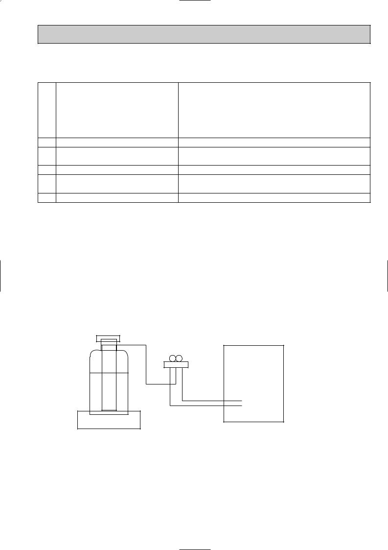
[3] Refrigerant recharging
(1) Refrigerant recharging process
1Direct charging from the cylinder.
·R407C cylinder are available on the market has a syphon pipe. ·Leave the syphon pipe cylinder standing and recharge it.
(By liquid refrigerant)
Unit
Gravimeter
(2) Recharge in refrigerant leakage case
·After recovering the all refrigerant in the unit, proceed to working. ·Do not release the refrigerant in the air.
·After completing the repair service, recharge the cycle with the specified amount of liquid refrigerant.
3
2 
 PART NAMES AND FUNCTIONS
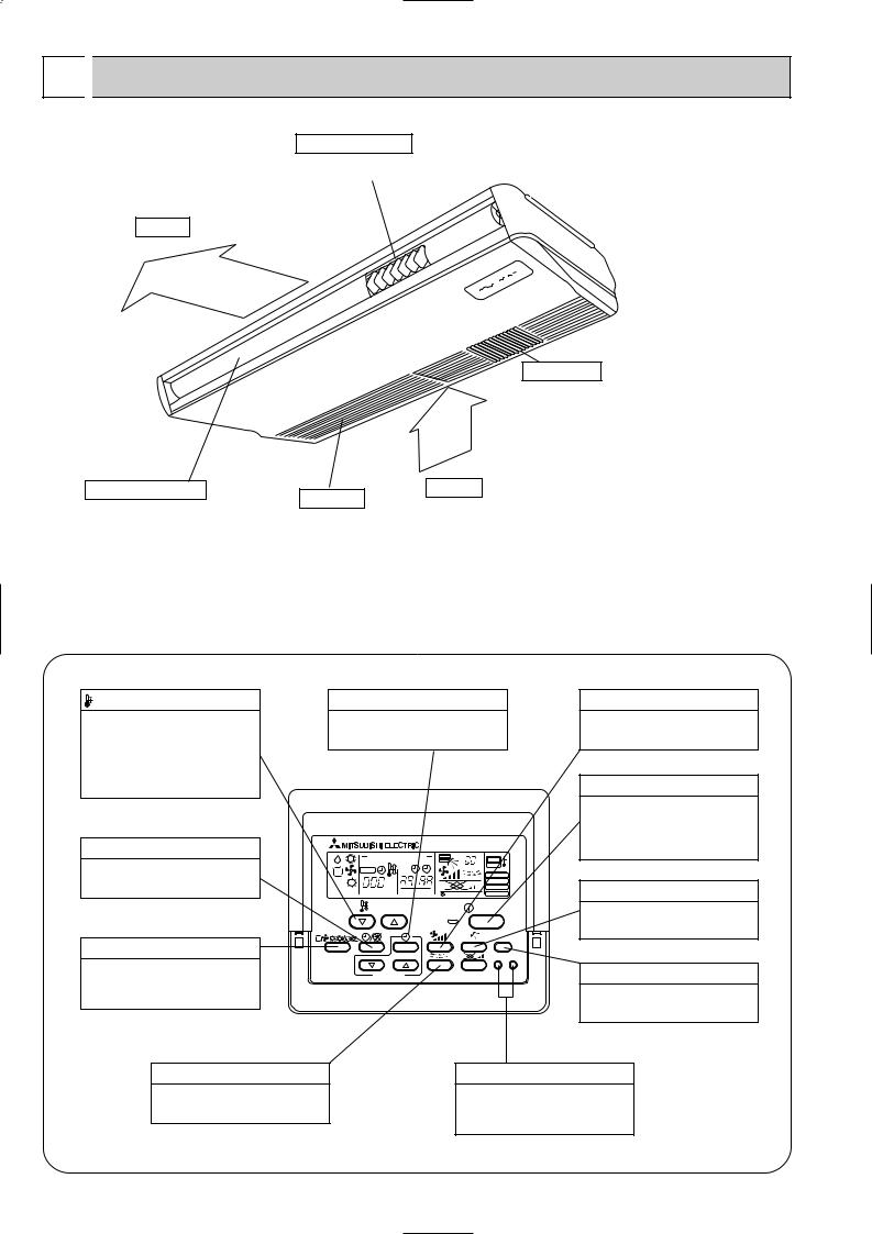
● Indoor (Main) Unit
Left/right guide vanes
Air outlet
Change the direction of airflow from the horizontal blower.
Long-life fillter
Removes dust and foreigh matter from air coming in through the grille (Recommended cleaning interval : Approx, every 2,500 operating hours)
Up/down guide vanes |
Air intake |
Change the direction of airflow from the |
Intake grille |
|
|
vartical blower. |
|
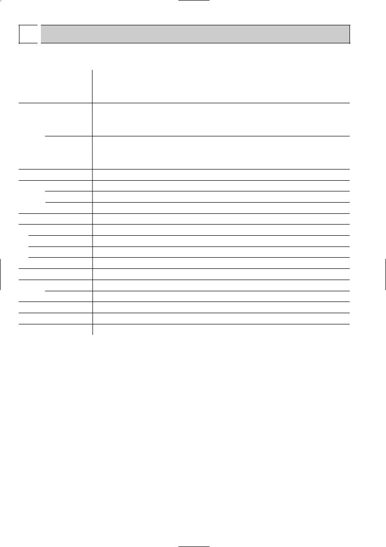
● Remote controller |
[PAR-20MAA] |
|
● Once the controls are set, the same operation mode can be repeated |
|
by simply pressing the ON/OFF button. |
● Operation buttons |
|
TEMP. ADJUSTMENT button |
TIME SETTING button |
AIR SPEED button |
|||
This sets the room temperature. The |
This sets the current time, start time |
This sets the ventilation fan speed. |
|||
temperature setting can be performed |
and stop time. |
|
|
||
|
|
|
|||
in 1: units |
|
|
|
|
|
Setting range |
|
|
|
|
|
Cooler 19: to 30: |
|
|
|
|
ON/OFF button |
Heater 17: to 28: |
|
|
|
|
|
|
|
|
|
|
This switches between the operation |
|
|
|
|
|
and stop modes each time it is pressed. |
|
|
|
|
|
The lamp on this button lights during |
TIMER button |
|
CENTRALLY CONTROLLED |
1Hr. |
operation. |
|
|
|
|
|||
This switches between continuous |
|
|
ON OFF |
˚C |
|
|
CHECK |
CLOCK |
FILTER |
|
|
operation and the timer operation. |
|
˚C |
|
CHECK MODE |
AIR DIRECTION button |
DEFROST |
|
TEST RUN |
|||
|
|
|
NOT AVAILABLE FUNCTION |
||
|
STAND BY |
|
ERROR CODE |
|
|
|
|
|
|
|
|
|
|
TEMP. |
|
ON/OFF |
This adjusts the vertical angle of the |
|
|
|
|
|
|
|
|
|
|
|
ventilation. |
|
|
|
|
FILTER |
|
OPERATION SWITCH button |
|
|
|
CHECK TEST |
|
|
|
|
|
|
|
Press this button to switch the cooler, |
PAR-20MAA |
TIMER SET |
|
FILTER button |
|
electronic dry (dehumidify), automatic |
|
|
|
|
|
and heater modes. |
|
|
|
|
This resets the filter service indication |
|
|
|
|
|
display |
LOUVER button |
|
|
|
CHECK-TEST RUN button |
|
This switch the horizontal fan motion |
|
|
Only press this button to perform an |
||
ON and OFF. |
|
|
|
inspection check or test operation. |
|
|
|
|
|
Do not use it for normal operation. |
|
(Not available for this model) |
|
|
|
|
|
4

● Display
CENTRALLY CONTROLLED display
This indicates when the unit is controlled by optional features such as central control type remote controller.
CLOCK display
The current time , start time and stop time can be displayed in ten second intervals by pressing the time switch button. The start time or stop time is always displayed during the timer operation.
In this display example on the bottom left, a condition where all display lamps light is shown for explanation purposes although this differs from actual operation.
TIMER display
This indicates when the continuous operation and time operation modes are set.
It also display the time for the timer operation at the same time as when it is set.
OPERATION MODE display
This indicates the operation mode.
STANDBY display
The [STANDBY] symbol is only displayed from the time the heating operation starts unit the heated air begins to blow.
DEFROST display
This indicates when the defrost operation is performed.
AIR DIRECTION display
This displays the air direction.
|
CENTRALLY CONTROLLED |
1Hr. |
|
|
|
|
ON OFF |
|
˚C |
|
CHECK |
CLOCK |
|
|
|
|
|
|
|
|
|
|
|
FILTER |
|
˚C |
|
|
CHECK MODE |
STAND BY |
ERROR CODE |
|
TEST RUN |
|
|
NOT AVAILABLE |
FUNCTION |
||
DEFROST |
|
|||
|
|
|||
|
TEMP. |
|
|
ON/OFF |
FILTER
CHECK TEST
PAR-20MAA |
TIMER SET |
AIR SPEED display
The selected fan speed is displayed.
ROOM TEMPERATURE display
The temperature of the suction air is displayed during operation. The display range is 8°C to 39°C. The display flashes 8°C when the actual temperature is less than 8°C and flashes 39°C when the actual temperature is greater than 39°C.
Operation lamp
This lamp lights during operation, goes off when the unit stops and flashes when a malfunction occurs.
CHECK MODE
display
TEST RUN
This display lights in the check mode or when a test operation is performed.
CHECK display |
|
|
|
|
|
|
|
SET TEMPERATURE display |
|
POWER display |
|
This indicates when a malfunction |
|||||
|
|
|
|
||
has occurred in the unit which should |
|
This displays the selected setting |
|
This lamp lights when electricity is |
|
be checked. |
|
|
|||
|
temperature. |
|
supplied to the unit. |
||
|
|
|
|||
|
|
|
|
|
Caution
FILTER display
This lamp lights when the filter need to be cleaned.
●Only the Power display lights when the unit is stopped and power supplied to the unit.
●When the central control remote control unit, which is sold separately, is used the ON-OFF button, operation switch button and  TEMP. adjustment button do not operate.
●“NOT AVAILABLE” is displayed when the Air speed button are pressed.This indicates that this room unit is not equipped with the fan direction adjustment function and the louver function.
●When power is turned ON for the first time, it is normal that “H0” is displayed on the room temperature indication (For max. 2minutes). Please wait until this “H0” indication disappear then start the operation.
5
3 
 SPECIFICATIONS
3-1. Specifications
|
|
|
|
Item |
|
PCFY-P40VGM-A |
|
PCFY-P63VGM-A |
|
PCFY-P100VGM-A |
|
PCFY-P125VGM-A |
||
|
|
|
|
|
|
|
|
|
|
|
|
|||
|
|
Power |
V·Hz |
|
|
Single phase 220-230-240V 50Hz / 220V 60Hz |
|
|||||||
Cooling capacity |
kW |
|
4.5 |
|
|
7.1 |
|
11.2 |
|
14.0 |
||||
Heating capacity |
kW |
|
5.0 |
|
|
8.0 |
|
12.5 |
|
16.0 |
||||
|
|
|
|
|
|
|
|
|
|
|
|
|
|
|
characteristic |
|
Input |
Cooling |
kW |
|
0.10 |
|
|
0.13 |
|
0.16 |
|
0.24 |
|
|
|
|
|
|
|
|
||||||||
|
|
Heating |
|
|
0.10 |
|
|
0.13 |
|
0.16 |
|
0.24 |
||
|
|
|
|
kW |
|
|
|
|
|
|||||
Electric |
|
Current |
Cooling |
A |
|
0.46 |
|
|
0.60 |
|
0.73 |
|
1.10 |
|
|
Heating |
A |
|
0.46 |
|
|
0.60 |
|
0.73 |
|
1.10 |
|||
|
|
|
|
|
|
|
|
|
|
|
|
|
||
|
|
|
|
|
|
|
|
|
|
|
|
|
|
|
|
|
Exterior |
— |
|
|
|
|
Unit : Munsell<0.70Y 8.59/0.97> |
|
|||||
(munsell symbol) |
|
|
|
|
|
|||||||||
|
|
|
|
Height |
mm |
|
|
210 |
|
|
270 |
|
||
Dimensions |
Width |
mm |
|
1000 |
|
|
1310 |
|
1310 |
|
1620 |
|||
|
|
|
|
|
||||||||||
|
|
|
|
Depth |
mm |
|
|
|
|
|
680 |
|
|
|
Heat exchanger |
— |
|
|
|
Cross fin (Aluminum plate fine and copper tube) |
|
||||||||
|
|
|
|
|
|
|
|
|
|
|||||
|
|
Fan No |
— |
Sirocco fan 2 |
|
Sirocco fan 3 |
|
Sirocco fan 4 |
||||||
F |
|
Air flow W |
k/min |
12 -11 -10 -8 |
|
|
18 -16 -14 -12 |
|
25 -23 -20 -18 |
|
35 -32 -28 -26 |
|||
|
|
|
|
|
||||||||||
a |
|
|
|
|
|
|||||||||
|
External |
|
|
|
|
|
|
0 |
|
|
||||
n |
|
Pa |
|
|
|
|
|
|
|
|||||
|
static pressure |
|
|
|
|
|
|
|
||||||
|
|
Fan motor |
kW |
|
0.054 |
|
|
0.07 |
|
0.09 |
|
0.15 |
||
|
|
output |
|
|
|
|
|
|||||||
|
|
Air filter |
— |
|
|
|
|
PP honey comb |
|
|||||
|
Pipe |
|
Gas |
[mm(in.) |
12.7(1/2") |
|
|
15.88(5/8") |
|
19.05(3/4") |
||||
|
|
|
|
|
||||||||||
|
|
side |
|
|
|
|||||||||
dimensions |
|
Liquid |
[mm(in.) |
6.35(1/4") |
|
|
9.52(3/8") |
|
9.52(3/8") |
|||||
|
|
|
|
side |
|
|
|
|||||||
Unit drain pipe size |
[mm |
|
|
|
I.D.26 (PVC pipe VP-20 connectable) |
|
||||||||
Noise level W |
dB |
|
38 -36 -33 -29 |
|
|
39 -37 -34 -32 |
|
43 -41 -38 -36 |
|
44 -42 -39 -37 |
||||
Product weight |
kg |
|
27 |
|
|
34 |
|
37 |
|
43 |
||||
|
|
|
|
|
|
|
|
|
|
|
|
|||
Note 1. |
Rating conditions(JIS B 8616) |
|
|
|
|
|
|
|
||||||
|
|
|
|
Cooling : |
Indoor : |
D.B. 27°C |
W.B. 19.0°C |
|
|
|
|
|||
|
|
|
|
|
|
outdoor : |
D.B. 35°C |
|
|
|
|
|
|
|
|
|
|
|
Heating : |
Indoor : |
D.B. 20°C |
|
|
|
|
|
|
|
|
|
|
|
|
|
|
outdoor : |
D.B. 7°C |
W.B. 6°C |
|
|
|
|
||
|
|
W. |
Air flow and the noise level are indicated as High-Middium 1-Middium 2-Low. |
|
||||||||||
6
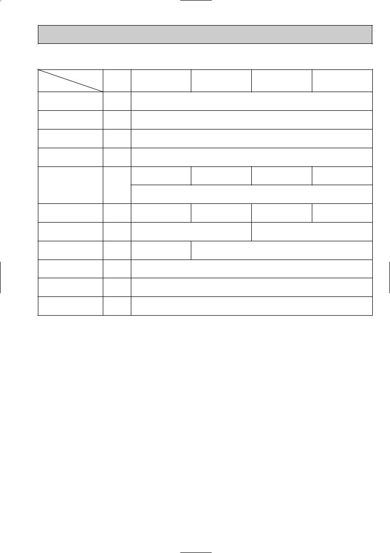
3-2. Electrical parts specifications
Model |
Symbol |
|
|
|
|
|
|
|
|
Parts name |
PCFY-P40VGM-A |
PCFY-P63VGM-A |
PCFY-P100VGM-A |
PCFY-P125VGM-A |
|||||
|
|
|
|
|
|
|
|
||
Room temperature |
TH21 |
Resistance 0:/15k", 10:/9.6k", 20:/6.3k", 25:/5.2k", 30:/4.3k", 40:/3.0k" |
|||||||
thermistor |
|||||||||
|
|
|
|
|
|
|
|
||
Liquid pipe temperature |
TH22 |
Resistance 0:/15k", 10:/9.6k", 20:/6.3k", 25:/5.2k", 30:/4.3k", 40:/3.0k" |
|||||||
thermistor |
|||||||||
|
|
|
|
|
|
|
|
||
Gas pipe temperature |
TH23 |
Resistance 0:/15k", 10:/9.6k", 20:/6.3k", 25:/5.2k", 30:/4.3k", 40:/3.0k" |
|||||||
thermistor |
|||||||||
|
|
|
|
|
|
|
|
||
Fuse |
FUSE |
|
|
250V 6.3A |
|
||||
(Indoor controller board) |
|
|
|
||||||
|
|
|
|
|
|
|
|
||
|
|
4-Pole Output 54W |
4-Pole Output 70W |
4-Pole Output 90W |
4-Pole Output 150W |
||||
Fan motor |
MF |
D09B4P54MS |
D09C4P70MS |
|
|
D10B4P90MS |
D10B4P150MS |
||
|
|
|
|
|
|
|
|||
(with inner-thermostat) |
|
|
|
|
|
|
|
||
|
Inner-thermostat |
OFF 130: I5: |
|
||||||
|
|
|
|||||||
Fan motor capacitor |
C1 |
3 F 440V |
4 F 440V |
|
|
4 F 440V |
6 F 440V |
||
Vane motor |
MV |
MP35EA |
|
|
|
MP42EA |
|||
DC12V |
|
|
|
DC12V |
|||||
|
|
|
|
|
|||||
|
|
DC12V Stepping |
|
|
DC12V Stepping motor drive |
||||
Linear expansion valve |
LEV |
motor drive |
|
|
|||||
|
|
|
[3.2 (0~2000pulse) |
|
|||||
|
|
[3.2 (0~2000pulse) |
|
|
|
|
|||
Power supply |
TB2 |
|
|
(L, N, ;) 330V 30A |
|
||||
terminal block |
|
|
|
||||||
|
|
|
|
|
|
|
|
||
Transmission |
TB5 |
|
|
(M1, M2, S) 250V 20A |
|
||||
terminal block |
|
|
|
||||||
|
|
|
|
|
|
|
|
||
MA remote controller |
TB15 |
|
|
(1, 2) |
250V |
10A |
|
||
terminal block |
|
|
|
||||||
|
|
|
|
|
|
|
|
||
7

3-3. NOISE CRITERION CURVES
CEILING
1m |
UNIT |
|
|
1m |
|
|
About 1.4m |
Ambient temperature 27:
Test conditions are based on JIS Z8731
|
|
|
|
|
MICROPHONE |
|||
PCFY-P40VGM-A |
|
NOTCH |
SPL(dB) |
LINE |
||||
|
|
|
|
|
|
Hi |
35 |
|
|
|
|
|
|
|
Mi1 |
33 |
|
|
|
|
|
|
|
Mi2 |
30 |
|
|
|
|
|
|
|
Lo |
27 |
|
BAR |
90 |
|
|
|
|
|
|
|
|
|
|
|
|
|
|
|
|
0.002 MICRO |
80 |
|
|
|
|
|
|
|
70 |
|
|
|
|
|
|
NC-70 |
|
dB re |
|
|
|
|
|
|
|
|
|
|
|
|
|
|
|
|
|
LEVEL, |
60 |
|
|
|
|
|
|
|
|
|
|
|
|
|
|
NC-60 |
|
|
|
|
|
|
|
|
|
|
PRESSURE |
50 |
|
|
|
|
|
|
|
|
|
|
|
|
|
|
NC-50 |
|
40 |
|
|
|
|
|
|
|
|
|
|
|
|
|
|
|
NC-40 |
|
SOUND |
|
|
|
|
|
|
|
|
30 |
|
|
|
|
|
|
NC-30 |
|
BAND |
|
|
|
|
|
|
|
|
20 |
|
|
|
|
|
|
|
|
OCTAVE |
|
|
|
|
|
|
|
|
|
|
|
|
|
|
|
NC-20 |
|
APPROXIMATE THRESHOLD OF HEARING |
|
|
|
|
||||
FOR CONTINUOUS NOISE |
|
|
|
|
|
|
||
10 |
|
|
|
|
|
|
|
|
|
|
|
|
|
|
|
|
|
|
63 |
125 |
250 |
500 |
1000 |
2000 |
4000 |
8000 |
BAND CENTER FREQUENCIES, Hz
PCFY-P100VGM-A |
|
NOTCH |
SPL(dB) |
LINE |
|||||
|
|
|
|
|
|
|
Hi |
39 |
|
|
|
|
|
|
|
|
Mi1 |
37 |
|
|
|
|
|
|
|
|
Mi2 |
35 |
|
|
|
|
|
|
|
|
Lo |
33 |
|
BAR |
90 |
|
|
|
|
|
|
|
|
|
|
|
|
|
|
|
|
|
|
0.002 MICRO |
80 |
|
|
|
|
|
|
|
|
70 |
|
|
|
|
|
|
|
NC-70 |
|
dB re |
|
|
|
|
|
|
|
|
|
|
|
|
|
|
|
|
|
|
|
LEVEL, |
60 |
|
|
|
|
|
|
|
|
|
|
|
|
|
|
|
|
NC-60 |
|
|
|
|
|
|
|
|
|
|
|
PRESSURE |
50 |
|
|
|
|
|
|
|
|
|
|
|
|
|
|
|
|
NC-50 |
|
40 |
|
|
|
|
|
|
|
|
|
|
|
|
|
|
|
|
|
NC-40 |
|
SOUND |
|
|
|
|
|
|
|
|
|
30 |
|
|
|
|
|
|
|
NC-30 |
|
BAND |
|
|
|
|
|
|
|
|
|
20 |
APPROXIMATE |
|
|
|
|
|
|
||
OCTAVE |
|
|
|
|
|
|
|||
|
THRESHOLD OF |
|
|
|
|
|
|
||
|
HEARING FOR |
|
|
|
|
|
NC-20 |
||
|
CONTINUOUS |
|
|
|
|
|
|
||
10 |
NOISE |
|
|
|
|
|
|
|
|
|
|
|
|
|
|
|
|
||
|
63 |
125 |
250 |
500 |
1000 |
2000 |
4000 |
8000 |
|
|
|
||||||||
BAND CENTER FREQUENCIES, Hz
PCFY-P63VGM-A |
|
NOTCH |
SPL(dB) |
LINE |
|||||
|
|
|
|
|
|
|
Hi |
37 |
|
|
|
|
|
|
|
|
Mi1 |
36 |
|
|
|
|
|
|
|
|
Mi2 |
34 |
|
|
|
|
|
|
|
|
Lo |
32 |
|
BAR |
90 |
|
|
|
|
|
|
|
|
|
|
|
|
|
|
|
|
|
|
0.002 MICRO |
80 |
|
|
|
|
|
|
|
|
70 |
|
|
|
|
|
|
|
NC-70 |
|
dB re |
|
|
|
|
|
|
|
|
|
|
|
|
|
|
|
|
|
|
|
LEVEL, |
60 |
|
|
|
|
|
|
|
|
|
|
|
|
|
|
|
|
NC-60 |
|
|
|
|
|
|
|
|
|
|
|
PRESSURE |
50 |
|
|
|
|
|
|
|
|
|
|
|
|
|
|
|
|
NC-50 |
|
40 |
|
|
|
|
|
|
|
|
|
|
|
|
|
|
|
|
|
NC-40 |
|
SOUND |
|
|
|
|
|
|
|
|
|
30 |
|
|
|
|
|
|
|
NC-30 |
|
BAND |
|
|
|
|
|
|
|
|
|
20 |
APPROXIMATE |
|
|
|
|
|
|
||
OCTAVE |
|
|
|
|
|
|
|||
|
THRESHOLD OF |
|
|
|
|
|
|
||
|
HEARING FOR |
|
|
|
|
|
NC-20 |
||
|
CONTINUOUS |
|
|
|
|
|
|
||
10 |
NOISE |
|
|
|
|
|
|
|
|
|
|
|
|
|
|
|
|
||
|
63 |
125 |
250 |
500 |
1000 |
2000 |
4000 |
8000 |
|
|
|
||||||||
BAND CENTER FREQUENCIES, Hz
PCFY-P125VGM-A |
|
NOTCH |
SPL(dB) |
LINE |
|||||
|
|
|
|
|
|
|
Hi |
39 |
|
|
|
|
|
|
|
|
Mi1 |
37 |
|
|
|
|
|
|
|
|
Mi2 |
35 |
|
|
|
|
|
|
|
|
Lo |
33 |
|
BAR |
90 |
|
|
|
|
|
|
|
|
|
|
|
|
|
|
|
|
|
|
0.002 MICRO |
80 |
|
|
|
|
|
|
|
|
70 |
|
|
|
|
|
|
|
NC-70 |
|
dB re |
|
|
|
|
|
|
|
|
|
|
|
|
|
|
|
|
|
|
|
LEVEL, |
60 |
|
|
|
|
|
|
|
|
|
|
|
|
|
|
|
|
NC-60 |
|
|
|
|
|
|
|
|
|
|
|
PRESSURE |
50 |
|
|
|
|
|
|
|
|
|
|
|
|
|
|
|
|
NC-50 |
|
40 |
|
|
|
|
|
|
|
|
|
|
|
|
|
|
|
|
|
NC-40 |
|
SOUND |
|
|
|
|
|
|
|
|
|
30 |
|
|
|
|
|
|
|
NC-30 |
|
BAND |
|
|
|
|
|
|
|
|
|
20 |
APPROXIMATE |
|
|
|
|
|
|
||
OCTAVE |
|
|
|
|
|
|
|||
|
THRESHOLD OF |
|
|
|
|
|
|
||
|
HEARING FOR |
|
|
|
|
|
NC-20 |
||
|
CONTINUOUS |
|
|
|
|
|
|
||
10 |
NOISE |
|
|
|
|
|
|
|
|
|
|
|
|
|
|
|
|
||
|
63 |
125 |
250 |
500 |
1000 |
2000 |
4000 |
8000 |
|
|
|
||||||||
BAND CENTER FREQUENCIES, Hz
8
9
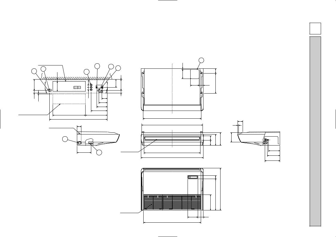
1 Drainage pipe connection (26mm I.D.)
2 Drainage pipe connection (for the left arrangement) 3 Knock out hole for left drain-piping arrangement
4 Refrigerant-pipe connection (gas pipe side/flared connection)
|
Electrical box |
( FRONT VIEW ) |
5 |
|
2 |
|
|
3 |
8 |
|
|
32 |
|
||
|
Ceiling |
|
|
|
|
|
|
179 |
161 |
38 79 |
|
42 |
~ 7 |
38 |
86 |
|
6 |
|
138 |
|
|
|
|
|
|
|
171 |
When electrical box |
|
263 |
|
is pulled down |
525 |
352 |
|
|
|
928 |
|
Electrical box |
70 |
|
7
226
2
5 Refrigerant-pipe connection (liquid pipe side/flared connection) |
|
-PCFY |
||
6 Knock out hole for upper drain pipe arrangement |
|
|
||
7 Knock out hole for left drain pipe arrangement |
|
|
||
8 Knock out hole for wiring arrangement |
6 |
|
||
|
|
|
A-P40VGM |
|
|
|
NOTES: |
|
|
|
|
1. Use M10 or W3/8 screws for anchor bolt. |
||
|
|
2. Please be sure when installing the drain-up machine (option parts). |
||
|
|
refrigerant pipe will be only upper drain pipe arrangement. |
||
1 |
4 |
17 |
|
|
|
|
|
||
|
|
|
80 |
|
|
1 |
150 |
|
|
131 |
175 |
140 |
70 |
320 |
|
|
|
||
|
46 |
|
|
|
933 (Suspension bolt pitch)
|
|
|
|
85 |
|
|
983 |
|
|
15 |
|
|
81 76 |
180 |
210 |
157 |
|
Air outlet |
904 |
|
|
182 |
(1/4F)liquid |
|
|
|
|
||
|
|
|
201 |
|
|
|
1000 |
|
|
(1/2F)gas |
|
|
|
|
|
|
|
|
|
|
|
241 |
(Drainage) |
|
|
56 |
|
|
|
|
|
506 |
680 |
|
|
|
|
|
|
|
|
|
254 |
|
|
|
|
Air intake
161 90
918
UNIT INDOOR
mm : Unit
DIMENSIONS AND OUTLINES 4
10
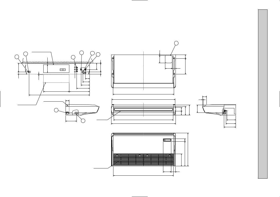
1 Drainage pipe connection (26mm I.D.) |
5 Refrigerant-pipe connection (liquid pipe side/flared connection) |
-PCFY |
2 Drainage pipe connection (for the left arrangement) |
6 Knock out hole for upper drain pipe arrangement |
|
3 Knock out hole for left drain-piping arrangement |
7 Knock out hole for left drain pipe arrangement |
|
4 Refrigerant-pipe connection (gas pipe side/flared connection) |
8 Knock out hole for wiring arrangement |
|
|
NOTES: |
A-P63VGM |
|
|
|
|
1. Use M10 or W3/8 screws for anchor bolt. |
|
|
2. Please be sure when installing the drain-up machine (option parts). |
|
|
refrigerant pipe will be only upper drain pipe arrangement. |
|
|
6 |
|
|
Electrical box |
|
( FRONT VIEW ) |
|
5 |
|
|
|
2 |
|
|
1 |
|
||
|
|
|
|
4 |
|||
|
|
|
|
|
|
||
|
|
|
|
|
|
|
|
3 |
|
32 |
|
8 |
|
|
1 |
|
|
Ceiling |
|
|
|
||
|
|
|
|
|
|
|
|
179 |
|
161 |
|
38 79 |
|
131 |
175 |
|
|
|
|
|
|
|
46 |
42 |
~ 7 |
|
|
38 |
86 |
|
|
|
6 |
|
|
|
|
|
|
|
|
|
|
138 |
|
|
|
|
|
|
|
|
|
|
|
|
|
|
|
|
171 |
|
|
|
|
|
|
|
263 |
|
|
|
|
|
525 |
|
416 |
|
|
|
|
|
1235 |
|
|
|
|
When electrical box |
Electrical box |
70 |
|
|
|
is pulled down |
|
|
|
7 |
|
Air outlet
226 2
Air intake
17 |
|
|
150 |
|
80 |
140 |
70 |
320 |
1240 (Suspension bolt pitch) |
|
|
|
|
|
|
85 |
1290 |
|
|
15 |
81 76 |
180 |
210 |
157 |
1214 |
|
|
|
1310 |
|
|
|
506 56 680
254
161 90
1228
182 (3/8F)liquid
201 (5/8F)gas
241 (Drainage)
mm : Unit
 Loading...