


Mitsubishi PEFY-P15VMS1(L)-E, PEFY-P20VMS1(L)-E, PEFY-P25VMS1(L)-E, PEFY-P32VMS1(L)-E, PEFY-P40VMS1(L)-E Service Manual
...2007
Air-Conditioners
TECHNICAL & SERVICE MANUAL
Models PEFY-P15VMS1(L)-E, PEFY-P40VMS1(L)-E PEFY-P20VMS1(L)-E, PEFY-P50VMS1(L)-E PEFY-P25VMS1(L)-E, PEFY-P63VMS1(L)-E PEFY-P32VMS1(L)-E
For use with R410A, R407C, & R22
Safety Precautions
Read before installation and performing electrical work
Thoroughly read the following safety precautions prior to installation.Observe these safety precautions for your safety.
This equipment may have adverse effects on the equipment on the same power supply system.Contact the local power authority before connecting to the system.
Symbol explanations
WARNING
This symbol indicates that failure to follow the instructions exactly as stated poses the risk of serious injury or death.
CAUTION
This symbol indicates that failure to follow the instructions exactly as stated poses the risk of serious injury or damage to the unit.
Indicates an action that must be avoided.
Indicates important instructions.
Indicates a parts that requires grounding.
Indicates that caution must be taken with rotating parts. (This symbol is on the main unit label.) <Color: Yellow>
Indicates that the parts that are marked with this symbol pose a risk of electric shock. (This symbol is on the main unit label.) <Color: Yellow>
WARNING
Carefully read the labels affixed to the main unit.
 WARNING
Ask your dealer or a qualified technician to install the unit.
Improper installation by the user may result in water leakage, electric shock, or fire.
Properly install the unit on a surface that can withstand its weight.
Unit installed on an unstable surface may fall and cause injury.
Only use specified cables. Securely connect each cable so that the terminals do not carry the weight of the cable.
Improperly connected cables may produce heat and start a fire.
Take appropriate safety measures against wind gusts and earthquakes to prevent the unit from toppling over.
Improper installation may cause the unit to topple over and cause injury or damage to the unit.
Only use accessories (i.e., air cleaners, humidifiers, electric heaters) recommended by Mitsubishi Electric.
Do not make any modifications or alterations to the unit. Consult your dealer for repair.
Improper repair may result in water leakage, electric shock, or fire.
Do not touch the heat exchanger fins with bare hands.
The fins are sharp and pose a risk of cuts.
In the event of a refrigerant leak, thoroughly ventilate the room.
If gaseous refrigerant leaks out and comes in contact with an open flame, toxic gases will be generated.
Properly install the unit according to the instructions in the Installation Manual.
Improper installation may result in water leakage, electric shock, or fire.
Have all electrical work performed by an authorized electrician according to the local regulations and the instructions in this manual. Use a dedicated circuit.
Insufficient power supply capacity or improper installation of the unit may result in malfunctions of the unit, electric shock, or fire.
HWE07120 |
i |
|
GB
-E, PEFY-P20VMS1(L)-E, PEFY-P25VMS1(L)-E, PEFY-P32VMS1(L)-E, PEFY-P40VMS1(L)-E Service Manual")
 WARNING
Keep electrical parts away from water.
Wet electrical parts pose a risk of electric shock, smoke, or fire.
Securely attach the control box cover.
If the cover is not installed properly, dust or water may infiltrate and pose a risk of electric shock, smoke, or fire.
Only use the type of refrigerant that is indicated on the unit when installing or relocating the unit.
Infiltration of any other types of refrigerant or air into the unit may adversely affect the refrigerant cycle and may cause the pipes to burst or explode.
When installing the unit in a small space, take appropriate precautions to prevent leaked refrigerant from reaching the limiting concentration.
Leaked refrigerant gas will displace oxygen and may cause oxygen starvation. Consult your dealer before installing the unit.
Consult your dealer or a qualified technician when moving or reinstalling the unit.
Improper installation may result in water leakage, electric shock, or fire.
After completing the service work, check for a refrigerant leak.
If leaked refrigerant is exposed to a heat source, such as a fan heater, stove, or electric grill, toxic gases will be generated.
Do not try to defeat the safety features of the unit.
Forced operation of the pressure switch or the temperature switch by defeating the safety features for these devices, or the use of accessories other than the ones that are recommended by Mitsubishi Electric may result in smoke, fire, or explosion.
Consult your dealer for proper disposal method.
Do not use a leak detection additive.
Precautions for handling units for use with R410A
 CAUTION
Do not use the existing refrigerant piping.
A large amount of chlorine that may be contained in the residual refrigerant and refrigerator oil in the existing piping may cause the refrigerator oil in the new unit to deteriorate.
Use refrigerant piping materials made of phosphorus deoxidized copper. Keep the inner and outer surfaces of the pipes clean and free of such contaminants as sulfur, oxides, dust, dirt, shaving particles, oil, and moisture.
Contaminants in the refrigerant piping may cause the refrigerator oil to deteriorate.
Store the piping materials indoors, and keep both ends of the pipes sealed until immediately before brazing. (Keep elbows and other joints wrapped in plastic.)
Infiltration of dust, dirt, or water into the refrigerant system may cause the refrigerator oil to deteriorate or cause the compressor to malfunction.
Use a small amount of ester oil, ether oil, or alkyl benzene to coat flares and flanges.
Infiltration of a large amount of mineral oil may cause the refrigerator oil to deteriorate.
Charge the system with refrigerant in the liquid phase.
If gaseous refrigerant is drawn out of the cylinder first, the composition of the remaining refrigerant in the cylinder will change and become unsuitable for use.
Only use R410A.
The use of other types of refrigerant that contain chloride may cause the refrigerator oil to deteriorate.
Use a vacuum pump with a check valve.
If a vacuum pump that is not equipped with a check valve is used, the vacuum pump oil may flow into the refrigerant cycle and cause the refrigerator oil to deteriorate.
Prepare tools for exclusive use with R 410A. Do not use the following tools if they have been used with the conventional refrigerant: gauge manifold, charging hose, gas leak detector, check valve, refrigerant charge base, vacuum gauge, and refrigerant recovery equipment.
If the refrigerant or the refrigerator oil that may be left on these tools are mixed in with R410A, it may cause the refrigerator oil in the new system to deteriorate.
Infiltration of water may cause the refrigerator oil to deteriorate. Leak detectors for conventional refrigerants will not detect an R410A leak because R410A is free of chlorine.
Do not use a charging cylinder.
If a charging cylinder is used, the composition of the refrigerant in the cylinder will change and become unsuitable for use.
Exercise special care when handling tools for use with R410A.
Infiltration of dust, dirt, or water into the refrigerant system may cause the refrigerator oil to deteriorate.
HWE07120 |
ii |
|
GB

CONTENTS |
|
I Features |
|
[1] Features.................................................................................................................................... |
1 |
II Components and Functions |
|
[1] Components and Functions...................................................................................................... |
2 |
III Specfications |
|
[1] Specifications............................................................................................................................ |
4 |
1.Specfications .......................................................................................................................... |
4 |
2.Electrical component specifications........................................................................................ |
6 |
IV Outlines and Dimensions |
|
[1] Outlines and Dimensions.......................................................................................................... |
7 |
V Wiring Diagram |
|
[1] Wiring Diagram ......................................................................................................................... |
9 |
VI Refrigerant System Diagram |
|
[1] Refrigerant system diagram.................................................................................................... |
11 |
VII Troubleshooting |
|
[1] Troubleshooting ...................................................................................................................... |
12 |
1.Check methods..................................................................................................................... |
12 |
2.DC fan motor (fan motor/indoor control board)..................................................................... |
16 |
3.Address switch setting .......................................................................................................... |
17 |
4.Voltage test points on the control board ............................................................................... |
18 |
5.Dipswitch setting (Factory setting)........................................................................................ |
19 |
VIII Disassembly Procedure |
|
[1] Disassembly Procedure.......................................................................................................... |
22 |
1.Control box ........................................................................................................................... |
22 |
2.Thermistor (Intake air) .......................................................................................................... |
23 |
3.Drainpan ............................................................................................................................... |
24 |
4.Thermistor (Gas pipe) (Liquid pipe) ...................................................................................... |
25 |
5.Fan and fan motor ................................................................................................................ |
26 |
6.Bearing ................................................................................................................................. |
27 |
7.Heat exchanger .................................................................................................................... |
28 |
HWE07120 |
GB |

HWE07120 |
GB |

[ I Features ]
[1] Features
Model |
Cooling capacity/Heating capacity |
|
|
|
kW |
|
|
PEFY-P15VMS1(L)-E |
1.7/1.9 |
|
|
PEFY-P20VMS1(L)-E |
2.2/2.5 |
|
|
PEFY-P25VMS1(L)-E |
2.8/3.2 |
|
|
PEFY-P32VMS1(L)-E |
3.6/4.0 |
|
|
PEFY-P40VMS1(L)-E |
4.5/5.0 |
|
|
PEFY-P50VMS1(L)-E |
5.6/6.3 |
|
|
PEFY-P63VMS1(L)-E |
7.1/8.0 |
|
|
HWE07120 |
- 1 - |
GB |
[ II Components and Functions ]
[1] Components and Functions
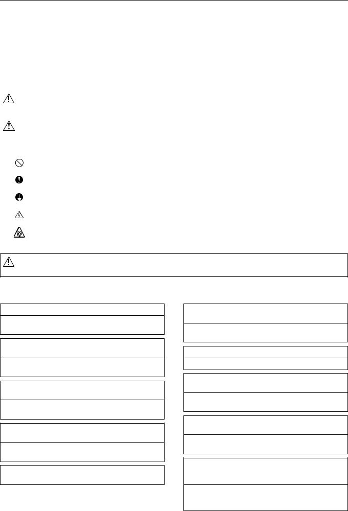
1. Indoor (Main) Unit
(A)
(A) Air
(A)
2.Remote Controller
[PAR-21MAA]
Once the operation mode is selected, the unit will remain in the selected mode until changed.
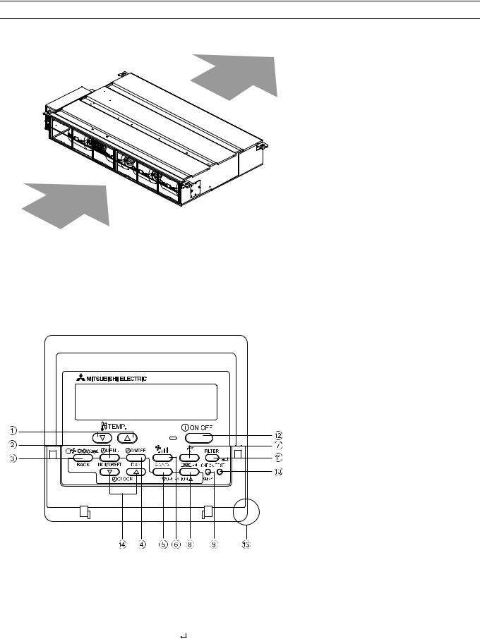
(1) Remote Controller Buttons
1 |
[Set Temperature] Button |
7 |
[Vane Control] Button |
|
2 |
[Timer Menu] Button |
8 |
[Ventilation] Button |
|
|
[Monitor/Set] Button |
|
[Operation] Button |
|
3 |
[Mode] Button |
9 |
[Check/Clear] Button |
|
|
[Back] Button |
10 |
[Test Run] Button |
|
4 |
[Timer On/Off] Button |
11 |
[Filter] Button |
|
|
[Set Day] Button |
|
[ |
] Button |
5 |
[Louver] Button |
12 |
[ON/OFF] Button |
|
|
[Operation] Button |
13 |
Position of built-in room thermistor |
|
6 |
[Fan Speed] Button |
14 |
[Set Time] Button |
|
Keep the remote controller out of direct sunlight to ensure accurate measurement of room temperature.
The thermistor at the lower right-hand section of the remote controller must be free from obstructions to ensure accurate measurement of room temperature.
HWE07120 |
- 2 - |
GB |
[ II Components and Functions ]
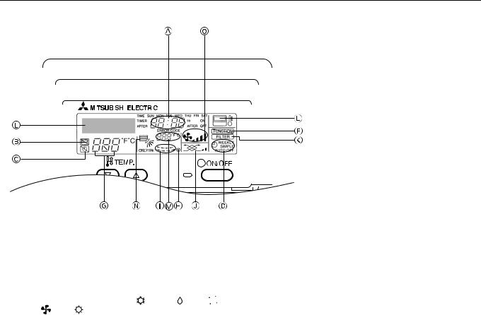
(2) Remote Controller Display
|
|
|
|
|
|
|
|
|
|
|
|
|
|
|
|
|
|
|
|
|
|
|
|
|
|
|
|
|
|
|
|
|
|
|
|
|
|
|
|
|
|
|
|
|
|
|
|
|
|
|
|
|
|
|
|
|
|
|
|
|
|
|
|
|
|
|
|
|
|
|
|
|
|
|
|
|
|
|
|
|
|
|
|
|
|
|
|
|
|
|
|
|
|
|
|
|
|
|
|
|
|
|
|
|
|
|
|
|
|
|
|
|
|
|
|
|
|
|
|
|
|
|
|
|
|
|
|
|
|
|
|
|
|
|
|
|
|
|
|
|
|
|
|
|
|
|
|
|
|
|
|
|
|
|
|
|
|
|
|
|
|
|
|
|
|
|
|
|
|
|
|
|
|
|
|
|
|
|
|
|
|
|
|
|
|
|
|
|
|
|
|
|
|
|
|
|
|
|
|
|
|
|
|
|
|
|
|
|
|
|
|
|
|
|
|
|
|
|
|
|
|
|
|
|
|
|
|
|
|
|
|
|
|
|
|
|
|
|
|
|
|
|
|
|
|
|
|
|
|
|
|
|
|
|
|
|
|
|
|
|
|
|
|
|
|
|
|
|
|
|
|
|
|
|
|
|
|
|
|
|
|
|
|
|
|
|
|
|
|
|
|
|
|
|
|
|
|
|
|
|
|
|
|
|
|
|
|
|
|
|
|
|
|
|
|
|
|
|
|
|
|
|
|
|
|
|
|
|
|
|
|
|
|
|
|
A |
Current time/Timer time |
|
|
I |
Louver swing |
||||||||||||||||||
B |
Centralized control indicator |
|
|
J |
Ventilation |
||||||||||||||||||
C |
Timer OFF indicator |
|
|
K |
Filter sign |
||||||||||||||||||
D |
Timer mode |
|
|
L |
Sensor position |
||||||||||||||||||
E |
Operation mode display: COOL, DRY, |
|
AUTO, |
|
|
M |
Room temperature |
||||||||||||||||
|
|
||||||||||||||||||||||
|
FAN, HEAT |
|
|
|
|
|
|
|
|||||||||||||||
F |
Function Lock indicator |
|
|
N |
Vane setting |
||||||||||||||||||
G |
Preset temperature |
|
|
O |
Fan speed |
||||||||||||||||||
H |
Power indicator |
|
|
|
|
||||||||||||||||||
HWE07120 |
- 3 - |
GB |

[ III Specfications ]
[1] Specifications
1. Specfications
Model |
|
|
PEFY- |
PEFY- |
|
PEFY- |
PEFY- |
|
|
|
P15VMS1(L)-E |
P20VMS1(L)-E |
P25VMS1(L)-E |
P32VMS1(L)-E |
|
|
|
|
|
|
|
|
|
Power supply |
Voltage |
V |
|
220-240 |
|
||
|
|
|
|
|
|
|
|
|
Frequency |
Hz |
|
|
50/60 |
|
|
|
|
|
|
|
|
|
|
Cooling capacity *1 |
|
kW |
1.7 |
2.2 |
|
2.8 |
3.6 |
Heating capacity *1 |
|
kW |
1.9 |
2.5 |
|
3.2 |
4.0 |
Power consumption |
Cooling |
kW |
0.05/0.05 |
0.05/0.05 |
|
0.06/0.06 |
0.07/0.07 |
|
|
|
|
|
|
|
|
|
Heating |
kW |
0.03/0.03 |
0.03/0.03 |
|
0.04/0.04 |
0.05/0.05 |
|
|
|
|
|
|
|
|
Current consumption |
Cooling |
A |
0.42/0.42 |
0.47/0.47 |
|
0.50/0.50 |
0.50/0.50 |
|
|
|
|
|
|
|
|
|
Heating |
A |
0.31/0.31 |
0.36/0.36 |
|
0.39/0.39 |
0.39/0.39 |
|
|
|
|
|
|
|
|
External finish (Munsel No.) |
|
|
Galvanized |
|
|||
|
|
|
|
|
|
|
|
Dimensions |
Height |
mm |
|
|
200 |
|
|
|
|
|
|
|
|
|
|
|
Width |
mm |
|
|
700 |
|
|
|
|
|
|
|
|
|
|
|
Depth |
mm |
|
|
700 |
|
|
|
|
|
|
|
|
|
|
Net weight *2 |
|
kg |
|
19(18) |
|
|
20(19) |
Heat exchanger |
|
|
Cross fin (Aluminium fin and cupper tube) |
||||
|
|
|
|
|
|
|
|
Fan |
Type |
|
|
Sirocco fan x 2 |
|
||
|
|
|
|
|
|
|
|
|
Airflow rate |
m3/min |
5.0-6.0-7.0 |
5.5-6.5-8.0 |
|
5.5-7.0-9.0 |
6.0-8.0-10.0 |
|
(Low-Mid-High) |
|
|
|
|
|
|
|
|
|
|
|
|
|
|
|
External static |
Pa |
5/15/35/50 |
5/15/35/50 |
|
5/15/35/50 |
5/15/35/50 |
|
pressure |
|
|
|
|
|
|
|
|
|
|
|
|
|
|
Motor |
Output |
kW |
|
|
0.096 |
|
|
|
|
|
|
|
|
|
|
Air filter |
|
|
|
PP Honeycomb fabric (washable) |
|
||
|
|
|
|
|
|
|
|
Refrigerant pipe di- |
Gas (Brazed |
mm |
|
ø12.7 [ø1/2] |
|
||
mensions (R410A) |
connection) |
[in.] |
|
|
|
|
|
|
|
|
|
|
|
||
|
Liquid (Brazed |
mm |
|
ø6.35 [ø1/4] |
|
||
|
connection) |
[in.] |
|
|
|
|
|
|
|
|
|
|
|
||
Refrigerant pipe di- |
Gas (Brazed |
mm |
|
ø12.7 [ø1/2] |
|
||
mensions (R22) |
connection) |
[in.] |
|
|
|
|
|
|
|
|
|
|
|
||
|
Liquid (Brazed |
mm |
|
ø6.35 [ø1/4] |
|
||
|
connection) |
[in.] |
|
|
|
|
|
|
|
|
|
|
|
|
|
Drain pipe dimensions |
|
mm |
|
O.D. 32 [1-9/32] |
|
||
|
|
[in.] |
|
|
|
|
|
|
|
|
|
|
|
|
|
Operating noise |
5Pa |
dB (A) |
22-24-26 |
22-25-28 |
|
23-25-29 |
24-27-30 |
(Low-Mid-High) |
|
|
|
|
|
|
|
15Pa |
|
22-24-28 |
22-25-29 |
|
24-26-30 |
24-27-32 |
|
|
|
|
|||||
|
|
|
|
|
|
|
|
|
35Pa |
|
24-26-29 |
25-27-30 |
|
25-28-31 |
25-28-33 |
|
|
|
|
|
|
|
|
|
50Pa |
|
24-27-30 |
25-28-32 |
|
25-29-33 |
25-29-34 |
|
|
|
|
|
|
|
|
*1 <Cooling> Indoor temperature: 27°CDB/19°CWB (81°FDB/66°FWB Outdoor temperature: 35°CDB (95°FDB) <Heating> Indoor temperature: 20°CDB (68°FDB) Outdoor temperature: 7°CDB/6°CWB (45°FDB/43°FWB)
*2 Figures in the parentheses indicate the weight of drainpump-less units (L).
HWE07120 |
- 4 - |
GB |

[ III Specfications ]
Model |
|
|
PEFY-P40VMS1(L)-E |
PEFY-P50VMS1(L)-E |
PEFY-P63VMS1(L)-E |
|
|
|
|
|
|
|
|
Power supply |
Voltage |
V |
|
220-240 |
|
|
|
|
|
|
|
|
|
|
Frequency |
Hz |
|
50/60 |
|
|
|
|
|
|
|
|
|
Cooling capacity *1 |
|
kW |
4.5 |
|
5.6 |
7.1 |
Heating capacity *1 |
|
kW |
5.0 |
|
6.3 |
8.0 |
Power consumption |
Cooling |
kW |
0.07/0.07 |
|
0.09/0.09 |
0.09/0.09 |
|
|
|
|
|
|
|
|
Heating |
kW |
0.05/0.05 |
|
0.07/0.07 |
0.07/0.07 |
|
|
|
|
|
|
|
Current consumption |
Cooling |
A |
0.56/0.56 |
|
0.67/0.67 |
0.72/0.72 |
|
|
|
|
|
|
|
|
Heating |
A |
0.45/0.45 |
|
0.56/0.56 |
0.61/0.61 |
|
|
|
|
|
|
|
External finish (Munsel No.) |
|
|
|
Galvanized |
|
|
|
|
|
|
|
|
|
Dimensions |
Height |
mm |
|
200 |
|
|
|
|
|
|
|
|
|
|
Width |
mm |
|
900 |
1100 |
|
|
|
|
|
|
|
|
|
Depth |
mm |
|
700 |
|
|
|
|
|
|
|
|
|
Net weight *2 |
|
kg |
|
24(23) |
28(27) |
|
Heat exchanger |
|
|
Cross fin (Aluminium fin and cupper tube) |
|||
|
|
|
|
|
|
|
Fan |
Type |
|
Sirocco fan x 3 |
Sirocco fan x 4 |
||
|
|
|
|
|
|
|
|
Airflow rate |
m3/min |
8.0-9.5-11.0 |
|
9.5-11.0-13.0 |
12.0-14.0-16.5 |
|
(Low-Mid-High) |
|
|
|
|
|
|
|
|
|
|
|
|
|
External static |
Pa |
5/15/35/50 |
|
5/15/35/50 |
5/15/35/50 |
|
pressure |
|
|
|
|
|
|
|
|
|
|
|
|
Motor |
Output |
kW |
|
0.096 |
|
|
|
|
|
|
|
|
|
Air filter |
|
|
|
PP Honeycomb fabric (washable) |
||
|
|
|
|
|
|
|
Refrigerant pipe di- |
Gas (Brazed |
mm |
ø12.7 [ø1/2] |
ø15.88 [ø5/8] |
||
mensions (R410A) |
connection) |
[in.] |
|
|
|
|
|
|
|
|
|
||
|
Liquid (Brazed |
mm |
ø6.35 [ø1/4] |
ø9.52[ø3/8] |
||
|
connection) |
[in.] |
|
|
|
|
|
|
|
|
|
|
|
Refrigerant pipe di- |
Gas (Brazed |
mm |
ø12.7 [ø1/2] |
|
ø15.88 [ø5/8] |
|
mensions (R22) |
connection) |
[in.] |
|
|
|
|
|
|
|
|
|
|
|
|
Liquid (Brazed |
mm |
ø6.35 [ø1/4] |
|
ø9.52[ø3/8] |
|
|
connection) |
[in.] |
|
|
|
|
|
|
|
|
|
|
|
Drain pipe dimensions |
|
mm |
|
|
O.D. 32 [1-9/32] |
|
|
|
[in.] |
|
|
|
|
|
|
|
|
|
|
|
Operating noise |
5Pa |
dB (A) |
26-29-32 |
|
29-31-34 |
29-32-35 |
(Low-Mid-High) |
|
|
|
|
|
|
15Pa |
|
28-30-33 |
|
30-32-35 |
30-33-36 |
|
|
|
|
||||
|
|
|
|
|
|
|
|
35Pa |
|
30-32-35 |
|
31-34-37 |
31-35-39 |
|
|
|
|
|
|
|
|
50Pa |
|
31-33-36 |
|
32-34-38 |
32-36-40 |
|
|
|
|
|
|
|
*1 <Cooling> Indoor temperature: 27°CDB/19°CWB (81°FDB/66°FWB Outdoor temperature: 35°CDB (95°FDB) <Heating> Indoor temperature: 20°CDB (68°FDB) Outdoor temperature: 7°CDB/6°CWB (45°FDB/43°FWB)
*2 Figures in the parentheses indicate the weight of drainpump-less units (L).
HWE07120 |
- 5 - |
GB |
[ III Specfications ]
2. Electrical component specifications
Component |
Sym- |
PEFY- |
|
|
PEFY- |
|
|
|
|
|
|
PEFY- |
|
|
PEFY- |
|||
|
bol |
P15VMS1(L)-E |
|
P20VMS1(L)-E |
|
|
|
|
|
|
P25VMS1(L)-E |
P32VMS1(L)-E |
||||||
|
|
|
|
|
|
|
|
|
|
|
|
|
|
|
|
|
||
Room temperature |
TH21 |
Resistance 0°C/15k |
, 10°C/9.6k |
, 20°C/6.3k |
, 25°C/5.4k |
, 30°C/4.3k |
, 40°C/3.0k |
|||||||||||
thermistor |
|
|
|
|
|
|
|
|
|
|
|
|
|
|
|
|
|
|
Liquid pipe thermistor |
TH22 |
Resistance 0°C/15k |
, 10°C/9.6k |
, 20°C/6.3k |
, 25°C/5.4k |
, 30°C/4.3k |
, 40°C/3.0k |
|||||||||||
|
|
|
|
|
|
|
|
|
|
|
||||||||
Gas pipe thermistor |
TH23 |
Resistance 0°C/15k |
, 10°C/9.6k , 20°C/6.3k , 25°C/5.4k , 30°C/4.3k , 40°C/3.0k |
|||||||||||||||
|
|
|
|
|
|
|
|
|
|
|
|
|
|
|
|
|
||
Fuse |
FUSE |
|
|
|
|
250V 6.3A |
|
|
|
|
|
|||||||
|
|
|
|
|
|
|
|
|
|
|
|
|
||||||
Fan motor |
|
|
8-pole, Output 96W SIC-70CW-D8114-1 |
|
|
|||||||||||||
|
|
|
|
|
|
|
|
|
|
|||||||||
Linear expansion valve |
LEV |
12VDC Stepping motor drive port diameter ø3.2 (0~2000 pulse) |
||||||||||||||||
|
|
|
|
|
|
|
|
|
|
|
|
|
|
|
|
|
|
|
Power supply terminal |
TB2 |
|
|
|
|
(L, N, |
|
|
|
|
) 330V 30A |
|
|
|
|
|
||
block |
|
|
|
|
|
|
|
|
|
|
|
|
|
|
||||
|
|
|
|
|
|
|
|
|
|
|
|
|
|
|
|
|
|
|
|
|
|
|
|
|
|
|
|
|
|
|
|
|
|
|
|
|
|
Transmission terminal |
TB5 |
|
|
|
(1, 2), (M1, M2, S) 250V 20A |
|
|
|
||||||||||
block |
TB15 |
|
|
|
|
|
|
|||||||||||
|
|
|
|
|
|
|
|
|
|
|
|
|
|
|
|
|
||
|
|
|
|
|
|
|
|
|
|
|
|
|
|
|
|
|
||
Drain float switch |
DS |
|
|
|
|
Open/short detection |
|
|
|
|
|
|||||||
|
|
|
Initial contact resistance 500 m |
or less |
|
|
||||||||||||
|
|
|
|
|
|
|
|
|
|
|
|
|
|
|
|
|||
|
|
|
|
|
|
|
|
|
|
|
|
|||||||
Component |
Sym- |
PEFY-P40VMS1(L)-E |
|
PEFY-P50VMS1(L)-E |
|
|
PEFY-P63VMS1(L)-E |
|||||||||||
|
bol |
|
|
|
|
|
|
|
|
|
|
|
|
|
|
|
|
|
|
|
|
|
|
|
|
|
|
|
|
|
|
|
|||||
Room temperature |
TH21 |
Resistance 0°C/15k |
, 10°C/9.6k |
, 20°C/6.3k |
, 25°C/5.4k |
, 30°C/4.3k |
, 40°C/3.0k |
|||||||||||
thermistor |
|
|
|
|
|
|
|
|
|
|
|
|
|
|
|
|
|
|
Liquid pipe thermistor |
TH22 |
Resistance 0°C/15k |
, 10°C/9.6k |
, 20°C/6.3k |
, 25°C/5.4k |
, 30°C/4.3k |
, 40°C/3.0k |
|||||||||||
|
|
|
|
|
|
|
|
|||||||||||
Gas pipe thermistor |
TH23 |
Resistance 0°C/15k |
, 10°C/9.6k , 20°C/6.3k , 25°C/5.4k , 30°C/4.3k , 40°C/3.0k |
|||||||||||||||
|
|
|
|
|
|
|
|
|
|
|
|
|
|
|
|
|||
Fuse |
FUSE |
|
|
|
|
250V 6.3A |
|
|
|
|
|
|||||||
|
|
|
|
|
|
|
|
|
|
|||||||||
Fan motor |
|
|
8-pole, Output 96W SIC-70CW-D896-2 |
|
|
|||||||||||||
|
|
|
|
|
|
|
||||||||||||
Linear expansion valve |
LEV |
12VDC Stepping motor drive port diameter ø3.2 (0~2000 pulse) |
||||||||||||||||
|
|
|
|
|
|
|
|
|
|
|
|
|
|
|
|
|
|
|
Power supply terminal |
TB2 |
|
|
|
|
(L, N, |
|
|
|
|
) 330V 30A |
|
|
|
|
|
||
block |
|
|
|
|
|
|
|
|
|
|
|
|
|
|
||||
|
|
|
|
|
|
|
|
|
|
|
|
|
|
|
|
|
|
|
|
|
|
|
|
|
|
|
|
|
|
|
|
|
|
|
|
|
|
Transmission terminal |
TB5 |
|
|
|
(1, 2), (M1, M2, S) 250V 20A |
|
|
|
||||||||||
block |
TB15 |
|
|
|
|
|
|
|||||||||||
|
|
|
|
|
|
|
|
|
|
|
|
|
|
|
|
|
||
|
|
|
|
|
|
|
|
|
|
|
|
|
|
|
|
|||
Drain float switch |
DS |
|
|
|
|
Open/short detection |
|
|
|
|
|
|||||||
|
|
|
Initial contact resistance 500 m |
or less |
|
|
||||||||||||
|
|
|
|
|
|
|
|
|
|
|
|
|
|
|
|
|
|
|
HWE07120 |
- 6 - |
GB |
 Loading...