


 Loading...
 MITSUBISHI ELECTRIC
Art. no.: 132733 01 11 2004 IB(NA)-0600081 Version C
FR-A 500/FR-F 500/ FR-E 500/FR-S 500/ FR-F 700 EC
Frequency Inverter
Instruction Manual
FR-SW1-SETUP-WE
Version 3.1
 MITSUBISHI ELECTRIC INDUSTRIAL AUTOMATION

INTRODUCTION
Thank you for choosing the Mitsubishi Transistorized VFD Setup Software.
This instruction manual gives handling information and precautions for use of this software.
Incorrect handling might cause an unexpected fault. Before using this product, please read this manual carefully to use it to the optimum.
Please forward this manual to the end user.
When reading this manual, note the following:
•This manual is written on the basis that Windows® 95 (English version) is the operating system.
• The [return] and [enter] keys are represented by the  key.
key.
•Drive D is described as the CD-ROM drive and Drive C as the hard disk drive.
•In keyboard operation, simultaneous pressing of keys is indicated by "+". Example: Pressing the [Alt] and [G] keys simultaneously is indicated by (Alt+G).
•The screens, parameter names, set values and so on given in this manual are written on the basis of the FRA500 series. When using the inverter of any other series, refer to the instruction manual of the used inverter.
Trademarks
•Microsoft and Windows are registered trademark or trademark of Microsoft Corporation in the United States and/ or other countries.
1)The formal name of Windows 95 is Microsoft® Windows® 95 operating system.
2)The formal name of Windows 98 is Microsoft® Windows® 98 operating system.
3)The formal name of Windows NT® is Microsoft® Windows NT® operating system.
4)The formal name of Windows® 2000 is Microsoft® Windows® 2000 operating system.
5)The formal name of Windows® Me is Microsoft® Windows® Me operating system.
6)The formal name of Windows® XP is Microsoft® Windows® XP operating system.
•The DOS/V personal computer is a registered trademark of IBM Corporation.
•The "Mitsubishi Transistorized VFD Setup Software" is a registered trademark of Mitsubishi Electric Corporation. The copyright and other rights of this software all belong to Mitsubishi Electric Corporation.
•No part of this manual may be copied or reproduced without the permission of Mitsubishi Electric Corporation.
•Other company and product names herein are the trademarks or registered trademarks of their respective owners.
 For Maximum Safety
•Mitsubishi vector inverters are not designed or manufactured to be used in equipment or systems in situations that can affect or endanger human life.
•When considering this product for operation in special applications such as machinery or systems used in passenger transportation, medical, aerospace, atomic power, electric power, or submarine repeating applications, please contact your nearest Mitsubishi sales representative.
•Although this product was manufactured under conditions of strict quality control, you are strongly advised to install safety devices to prevent serious accidents when it is used in facilities where breakdowns of the product are likely to cause a serious accident.

CONTENTS
1 OVERVIEW |
1 |
||
1.1 |
Before Using This Software ................................................................................ |
2 |
|
1.1.1 |
Packing list ................................................................................................................................ |
2 |
|
1.2 |
Preparations for Startup...................................................................................... |
3 |
|
1.2.1 |
System configuration ................................................................................................................. |
3 |
|
1.2.2 Installing the Setup Software ..................................................................................................... |
4 |
||
2 FUNCTIONS |
7 |
||
|
|
|
|
2.1 |
Starting the VFD Setup Software........................................................................ |
8 |
|
2.2 |
Settings................................................................................................................. |
9 |
|
2.2.1 |
System Settings....................................................................................................................... |
11 |
|
2.2.2 |
Communication Settings.......................................................................................................... |
12 |
|
2.2.3 |
Environmental Setting ............................................................................................................. |
13 |
|
2.3 |
Parameter ........................................................................................................... |
14 |
|
2.3.1 |
All List Format.......................................................................................................................... |
14 |
|
2.3.2 |
Functional List Format ............................................................................................................. |
17 |
|
2.3.3 |
Individual List Format .............................................................................................................. |
18 |
|
2.3.4 |
Basic Settings.......................................................................................................................... |
19 |
|
2.4 |
Monitor................................................................................................................ |
20 |
|
2.4.1 |
Data Display ............................................................................................................................ |
20 |
|
2.4.2 |
Meter Display........................................................................................................................... |
21 |
|
2.4.3 |
Oscilloscopes .......................................................................................................................... |
21 |
|
2.4.4 |
Alarm History ........................................................................................................................... |
23 |
|
2.4.5 Trace Oscilloscopes (for FR-V500 (L) series only).................................................................. |
24 |
||
2.5 |
Diagnosis............................................................................................................ |
33 |
|
2.5.1 |
VFD Status .............................................................................................................................. |
33 |
|
2.5.2 |
Diagnosis................................................................................................................................. |
33 |
|
2.6 |
Test Running ...................................................................................................... |
35 |
|
2.6.1 |
Test Running ........................................................................................................................... |
35 |
|
2.6.2 |
Auto Tuning ............................................................................................................................. |
35 |
|
2.7 |
Advanced Function............................................................................................ |
37 |
|
2.7.1 Machine analyzer (for FR-V500 (L) series only)...................................................................... |
37 |
||
2.8 |
Saving, Reading and Printing the Files ........................................................... |
42 |
|
2.8.1 |
File types ................................................................................................................................. |
42 |
|
2.8.2 |
Saving method......................................................................................................................... |
42 |
|
2.8.3 |
Reading the file........................................................................................................................ |
42 |
|
2.8.4 |
Printing .................................................................................................................................... |
42 |
|
2.9 |
Help ..................................................................................................................... |
43 |
|
2.9.1 |
Help contents........................................................................................................................... |
43 |
|
2.9.2 |
Version information.................................................................................................................. |
43 |
|
3 ERROR INDICATIONS |
45 |
||
|
|
|
|
3.1 |
Error codes......................................................................................................... |
46 |
|
3.1.1 |
Error code lists......................................................................................................................... |
46 |
|
3.1.2 |
Panel-displayed errors............................................................................................................. |
46 |
|
4 APPENDICES |
47 |
||
|
|
|
|
4.1 |
Supplementary Software................................................................................... |
48 |
|
4.1.1 |
Introduction.............................................................................................................................. |
48 |
4.1.2 |
Parameter files ........................................................................................................................ |
48 |
4.1.3 Parameter file edit software (PREDITE).................................................................................. |
49 |
|

1  OVERVIEW
This chapter provides the fundamental "overview" for use of this product.
Always read the instructions before using this software.
1.1 |
Before Using This Software ........................................... |
2 |
1.2 |
Preparations for Startup................................................. |
3 |
When using this software to make communication with the inverters, set a value other than 0 in Pr. 122 "communication check time interval" on the inverter's operation panel. When using the FR-A5NR, set any value other than 0 in Pr. 336 "communication check time interval", and when using the FR-S500 series, set any value other than 0 in the communication parameter n6 (336) "communication check time interval".
(Refer to the inverter instruction manual for the setting method.)
1
2
3
4
1

Before Using This Software
1.1 Before Using This Software
•This software can be used effectively as a support tool for operations from startup to maintenance of the Mitsubishi transistorized inverter. The following functions can be performed efficiently on the Windows screen of a personal computer.
System setting function
Parameter editing function
Monitoring function
Diagnosis function
Test running function
File management function
Advanced function
Help function
1.1.1Packing list
After unpacking, check that the following items are contained in the package:
Item |
Quantity |
CD-ROM |
1 disk |
Instruction manual |
1 book |
2

Preparations for Startup
1.2 Preparations for Startup
1.2.1System configuration
The following devices are required to use the VFD Setup Software. Configure the system in accordance with the instruction manuals of the corresponding devices.
|
|
3) |
|
|
|
|
|
|
|
|
|
|
|
|
|
|
|
|
|
|
|
|
|
|
|
|
|
|
|
|
|
|
|
|
|
|
|
|
|
|
|
|
|
|
|
|
|
1) |
|
|
|
|
||||
|
|
|
|
|
|
|
|
|
|
|
|
|
|
|
|
|
|
|
|
VFD Setup Software |
|
|
|
|
|
|
|
|
|||||||||
|
|
|
|
|
|
|
|
|
|
|
|
|
|
|
|
|
|
|
|
|
|
|
Converter |
*1 |
|
|
|
|
|
|
|
||||||
|
|
|
|
|
|
|
|
|
|
|
|
|
|
|
|
|
|
|
|
Communication option used *2 |
|
|
|
|
|
|
|
|
|||||||||
|
|
|
|
|
|
|
|
PU connector used *2 |
|
|||||||||
|
|
Connection cable |
|
|
|
|
|
|
|
|
||||||||
|
|
Connector: RJ45 connector |
|
|
|
|
|
|
|
|
||||||||
|
|
Example: Tyco Electronics Corporation 5-554720-3 |
|
|||||||||||||||
Connection cable |
Cable: Cable in compliance with EIA568 |
|
||||||||||||||||
RS-485/RS-422 |
(such as 10BASE-T cable) |
|
|
|
|
|
|
|
|
|||||||||
|
|
Example: Mitsubishi Cable Industries, Ltd., |
|
|||||||||||||||
|
|
|
||||||||||||||||
|
|
|
SGLPEV-T 0.5mm × 4P |
|
|
|
|
|
|
|
|
|||||||
|
|
|
(Twisted pair cable, 4 pairs) |
|
||||||||||||||
|
|
Distribution terminal |
|
|
|
|
|
|
|
|
|
|
|
|
|
|||
|
|
|
|
|
|
|
|
|
|
|
|
|
|
|
|
|||
|
|
|
|
|
|
|
|
|
|
|
|
|
|
|
||||
|
|
|
|
|
|
|
|
|
|
|
|
|
|
|
|
|
|
|
|
|
|
|
|
|
|
|
|
|
|
|
|
|
|
|
|
|
|
2)
Mouse
Printer cable
Commercially available printer
(ESC/P compatible)
Multidrop link system
Termination resistor
|
FR-A5NR |
|
|
|
|
|
Power supply |
NFB |
|
|
|
|
|
|
Inverter |
Inverter |
Inverter |
Inverter |
Inverter |
|
|
|
|||||
|
|
|
|
|
|
4) Inverters |
Motors
*1: A converter commercially available is required when the personal computer uses the RS-232C port. <Example of a commercially available product>
Model: FA-T-RS40 
 Converter (Model with connectors and cable is also available) Mitsubishi Electric Engineering Co., Ltd.
 The converter cable cannot connect two or more inverters (the computer and inverter are
connected on a 1:1 basis). Since the product is packed with the RS-232C cable and RS-485 cable (10BASE-T + RJ-45 connector), the cable and connector need not be prepared separately.
*2: The PU connector or FR-A5NR (FR-A500 (L) / F500 (L) / V500 (L) series) can be used to make communication. (Refer to the corresponding instruction manual for details.)
|
|
Model, Specifications, Etc. |
1) |
Personal computer |
One on which Windows 95, Windows 98, Windows NT 4.0, Windows 2000, Windows Me or Windows |
|
|
XP (English version) operates |
2) |
Mouse |
Mouse which can be connected to the personal computer |
3) |
Setup software |
VFD Setup Software (FR-SW1-SETUP-WE) |
FR-A520 (-NA), FR-A540 (-NA) (-EC) (-CH), FR-A560-NA,
FR-A520L-75K, 90K, FR-A540L-65K*, 75K to 450K (-NA) (-G-NA) (-EC) (-G-EC), FR-A540L-S-60K to 375K (-EC) (-CH), FR-A560L-NA-75K to 450K,
FR-E520-0.1K to 7.5K (-NA), FR-E540-0.4K to 7.5K (-NA) (-EC) (-CH),
FR-E520S-0.1K to 0.75K, FR-E520S-0.4K to 2.2K-EC (-CH), FR-E510W-0.1K to 0.75K (-NA), FR-F520-0.75K to 55K (-NA), FR-F540-0.75K to 55K (-NA) (-EC) (-CH),
4) Inverter FR-F520L-75K to 110K, FR-F540L-75K to 530K (-NA) (-EC) (-CH) (-G-CH), FR-F540L-S-75K to 400K (-CH), FR-F720-0.75K to 55K, FR-F720-00046 to 02330 (-NA)
FR-F740-0.75K to 160K, FR-F740-00023 to 03610 (-NA) (-EC) FR-F740-0.75K to 55K, S75K to S185K (-CH)
FR-S520-0.1K to 3.7K-R, FR-S540-0.4K to 3.7K-R (-NAR) (-ECR) (-CHR),
FR-S520S-0.1K to 1.5K-R, FR-S520S-0.2K to 1.5K-ECR (-CHR), FR-S510W-0.1K to 0.75K-R FR-V520, FR-V540, FR-V520L-75K, FR-V540L-75K to 250K (-NA)
* For the 65K, only (-NA), (-G-NA), (-EC), and (-G-EC) are supported.
1
OVERVIEW
3
Preparations for Startup
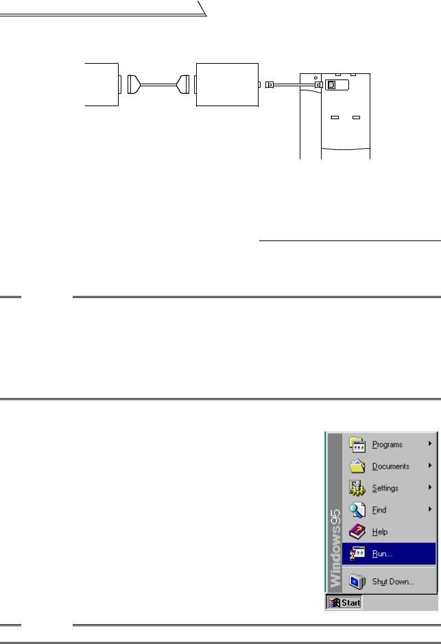
[Connection example between converter and inverter (PU connection port)]
Personal computer |
FA-T-RS40 |
RS-232C |
(RS-232C-RS-485 |
|
port |
||
converter) |
||
|
||
RS-232C |
RS-485 |
|
cable |
cable |
Inverter |
PU |
connection |
port |
1.2.2Installing the Setup Software
To use the VFD Setup Software (FR-SW1-SETUP-WE), the files included in the setup disks must be installed onto the personal computer.
When using an old version inverter setup software, move the setting file you have created from the default folder
where the file is placed to another folder. Also, be sure to uninstall *4 the old version software before installing a new setup software.
To install the VFD Setup Software, use the setup program (SETUP.EXE) on the Setup Disk (CD-ROM). The setup program creates a directory on the specified hard disk and copies the required files.
CAUTION
1.Since the files in the Setup Disk are compressed, the VFD Setup Software will not operate by merely copying the files. Always use the setup program to install the software.
2.Install the software in accordance with the Windows installation procedure.
3.When installing on Windows 95, be sure to install Microsoft DCOM95 for Windows 95, Version 1.3 before installing setup software. You can download DCOM95 for Windows 95, Version 1.3 from the following website of Microsoft Corporation. Note that URL is subject to variation.
http://www.microsoft.com/com/
4.For uninstallation, use [Uninstall] of the inverter setup software or [Setting] of the [Start] menu-[Add/ Remove Programs Properties] of [Control panel].
•Installation procedure
Use the following procedure to register (install) the VFD Setup Software onto the hard disk drive of the personal computer:
(1)Insert the CD-ROM into the CD-ROM drive.
(2)Press the [Start] button and choose the [Run] command.
CAUTION
Close any other applications that have already been started.
4
Preparations for Startup
(3)Running the installation program
1)The [Run] dialog box appears.
2)Type "D:\SETUP" (use half-size letters) in [Open] and click the [OK] button or press the  key. (When the CD-ROM drive is drive D)
3)After that, perform operation in accordance with the setup guide (screen).
(4)When file copying is over, the following screen appears. Always enter the user and company names and click the [OK] button.
Installation is not completed unless the user and company names are entered.
(5)When installation is finished, the "Uninstall", "VFD Setup S/W" and "VFD Setup S/W Help" icons are registered and the following screen appears.
1
OVERVIEW
5
MEMO
6

2  FUNCTIONS
This chapter describes the "functions" for use of this product. Always read the instructions before using this software.
2.1 |
Starting the VFD Setup Software................................... |
8 |
2.2 |
Settings.......................................................................... |
9 |
2.3 |
Parameter .................................................................... |
14 |
2.4 |
Monitor......................................................................... |
20 |
2.5 |
Diagnosis ..................................................................... |
33 |
2.6 |
Test Running................................................................ |
35 |
2.7 |
Advanced Function ...................................................... |
37 |
2.8 |
Saving, Reading and Printing the Files........................ |
42 |
2.9 |
Help ............................................................................. |
43 |
1
2
3
4
7
Starting the VFD Setup Software
2.1 Starting the VFD Setup Software
Start the VFD Setup Software with "INVSUPE.EXE".
CAUTION
Start only one VFD setup software program.
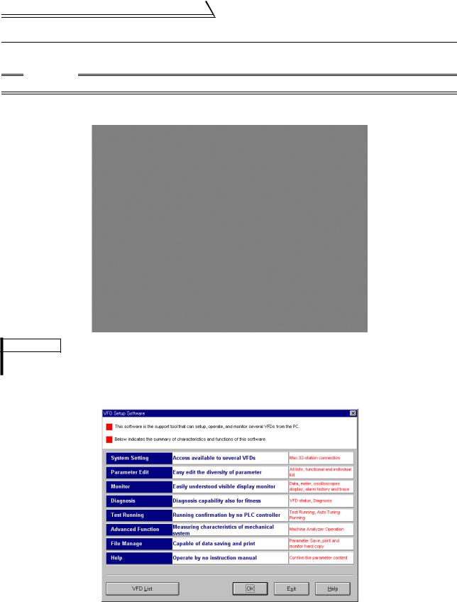
<Primary screen>
REMARKS
If check box "next time no disp." is checked, the above screen will not be displayed from the next time.
To display it again, check the check box "Display the initial screen", see section "2.2.3 Environmental Setting" (refer to page 13).
<Initial screen>
8
Settings
2.2 Settings
When you press the [OK] button on the initial screen, the following screen appears:
1)2) 3) 4)
 5)
5)
|
|
|
|
|
|
|
|
|
|
(1) Menu list |
|
|
6) |
7) |
8) |
||||
|
|
|
|
|
|
|
|
||
This software has the following functions: |
|
|
|
|
|
|
|||
|
|
|
|
|
|
|
|||
Menu |
Pull-Down Menu |
|
|
|
Function/Operation |
||||
|
Open |
Ctrl+O |
Opens a file. |
|
|
|
|
||
|
Close |
|
Closes the screen. |
|
|
|
|
||
File |
Save |
Ctrl+S |
Saves data. |
|
|
|
|
||
(Alt+F) |
|
|
|
|
|
|
|
||
Save As |
Ctrl+A |
Save data with a new name. |
|
|
|||||
|
Ctrl+P |
Selects printing. |
|
|
|
|
|||
|
Exit |
|
Performs exiting procedure. |
|
|
||||
|
System Settings |
Sets the model, capacity (size) and option type. (Stations 00 to 31) |
|||||||
Settings |
|
|
|
|
|
||||
Communication Settings |
Sets serial communication information. |
||||||||
(Alt+S) |
|
|
|
|
|
|
|||
Environmental Settings |
Sets the directory where data will be stored and sets re-display of the initial |
||||||||
|
screen. |
|
|
|
|
||||
|
|
|
|
|
|
|
|||
|
|
|
|
|
|
|
|||
|
All list Format |
Shows and sets the parameter list. |
|
|
|||||
Parameter |
Functional List Format |
Shows and sets the related parameters function-by-function. |
|||||||
Individual list Format |
You can register or delete a total of 32 parameters out of all parameters to |
||||||||
(Alt+P) |
or from two different user groups. |
|
|
||||||
|
|
|
|
||||||
|
|
|
|
|
|
|
|||
|
Basic Settings |
You can set the parameters required for starting up the inverter without |
|||||||
|
being aware of parameter numbers. |
|
|
||||||
|
|
|
|
|
|||||
|
Data Display |
Shows four pieces of data (up to four stations) in terms of values. |
|||||||
Monitor |
Meter Display |
Shows four pieces of data (up to four stations) in terms of meter deflections. |
|||||||
Oscilloscopes |
Shows four pieces of data (up to four stations) in terms of waveforms. |
||||||||
(Alt+M) |
|||||||||
Alarm History |
Shows the alarm history of all inverter stations connected. |
||||||||
|
|||||||||
|
Trace Oscilloscopes |
Analyzes various types of data. |
|
|
|||||
Diagnosis |
VFD Status |
Shows various data of all stations connected in real time in terms of values. |
|||||||
|
|
Examine the estimated cause of the alarm in accordance with the alarm |
|||||||
(Alt+N) |
Diagnosis |
||||||||
display. |
|
|
|
|
|||||
|
|
|
|
|
|
|
|||
|
|
|
|
|
|
|
|||
|
Test Running |
Gives the operation command from the personal computer to actually test |
|||||||
Test Running |
run the inverter. |
|
|
|
|
||||
|
|
|
|
|
|
||||
(Alt+T) |
|
|
|
|
|
|
|||
Auto Tuning |
Performs auto tuning in accordance with the motor connected to the |
||||||||
|
inverter. |
|
|
|
|
||||
|
|
|
|
|
|
|
|||
Advanced function |
Machine Analyzer |
Measures the response frequency characteristic of speed relative to the |
|||||||
(Alt+V) |
motor torque of the machine. |
|
|
||||||
|
|
|
|
||||||
Window |
Cascade Display |
Overlapping Windows. |
|
|
|
|
|||
(Alt+W) |
|
|
|
|
|
|
|||
Tile Display |
Windows are side-by-side. |
|
|
||||||
Help |
Contents |
Various help functions (parameter explanations, function explanations, etc.) |
|||||||
|
|
Version information (copyright, version information, user and company |
|||||||
(Alt+H) |
About VFD Setup S/W |
||||||||
names, etc.) |
|
|
|
|
|||||
|
|
|
|
|
|
|
|||
|
|
|
|
|
|
|
|
|
|
2
FUNCTIONS
9

Settings
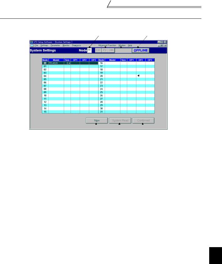
(2)Description of various buttons and indications
1)Node
The station number selected is displayed.
2)[EXT] (Alt+X), [PU] (Alt+U) and [LNK] (Alt+L) buttons
You can choose the inverter operation mode for online operation.
[EXT] button: External operation mode
[PU] button: PU operation mode
[LNK] button: Computer link operation mode
3)The operation mode and error codes appear. (Refer to page 46 for the error codes.) Operation mode indications
EXT............................ |
External operation mode |
PU.............................. |
PU operation mode |
EXT JOG ................... |
External jog mode |
PU JOG ..................... |
PU jog mode |
LNK............................ |
Computer link mode |
PU EXT...................... |
PU-external combined mode |
TIME .......................... |
Time scheduled operation |
SP.............................. |
Special mode |
No Node..................... |
Time-out occurred in the online mode |
In any other case, the error number at NAK error occurrence appears.
When an alarm occurs, the operation mode and error codes are displayed in red.
To display a warning, the operation mode and warning appear.
4)[ONLINE/OFFLINE] (Alt+O) button
[ONLINE] (online) button: Online operation mode
[OFFLINE] (offline) button: Offline operation mode
Click the corresponding button to select the online or offline mode.
5)System settings
You can set the environment of the inverters of stations 00 to 31. Set the model, capacity and options for these inverters.
6)[New] button (Alt+E)
Used to make new system settings.
7)[System Read] button (Alt+Y)
Used to batch-read all inverters in the system with which the personal computer communicates.
8)[Confirmed] button (Alt+I)
You can register the data specified in the system settings. Always confirm the entry with the [Confirmed] button when you have changed the setting of the system configuration manually.
10
Settings
2.2.1System Settings
This screen appears when you start this software and press the [OK] button on the initial screen.
On this screen, set the station numbers, models, capacities and plug-in options of the inverters connected. Inverters can be set to stations 0 to 31.
(1) Station selection (Ctrl+N)
Click the required station number. That line is then chosen.
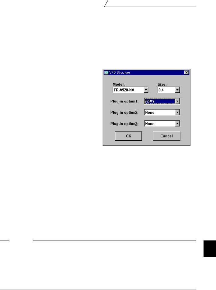
(2) Selection of model, capacity and options
When you double-click the selected line, the "VFD Structure" panel (as shown on the right) appears. Set the model, capacity and options and press the [OK] button to complete the settings. Using the same procedure, set all inverter stations which connected.
(3) [Confirmed] button (Alt+I)
After setting all stations, pressing the Confirmed button completes the system settings.
(4) [New] button (Alt+E)
Press the New button to initialize (clear) the system settings/communication settings being edited.
(5) [System Read] button (Alt+Y)
Before pressing the [System Read] button, press the [ONLINE/OFFLINE] button to change the mode indication to [ONLINE] and select the online operation mode. In the online operation mode, the personal computer is switched to the inverter communication status and clicking the [System Read] button reads the models, capacities and options of all stations (stations 0 to 31) and displays the stations connected (with which the personal computer can communicate).
After reading, the settings are registered automatically.
When the system settings have not yet been made, the read stations are displayed. When the system settings have already been registered, check is performed. If the check result is different from the read data, select whether different points are displayed and changed or not.
CAUTION
1.When the [Cancel] button is clicked during [System Read], the system setting made until then is verified.
2.• When the [System Read] button is pressed, the 100V or 200V class of the FR-E500 series is displayed as the FR-E520-NA, the 400V class as the FR-E540-NA.
•When the [System Read] button is pressed, the 100V class of the FR-S500 series as the 200V class.
•During [System Read] of the FR-F520 and the FR-F540(L), the models are displayed as the FR-F520- NA and the FR-F540(L)-NA.
•During [System Read] of the FR-F540L-G-CH, the model is displayed as the FR-F540L-S-CH and the
capacity is the value one rank lower.
When the model and the capacity differ, change them manually.
2
FUNCTIONS
11
Settings
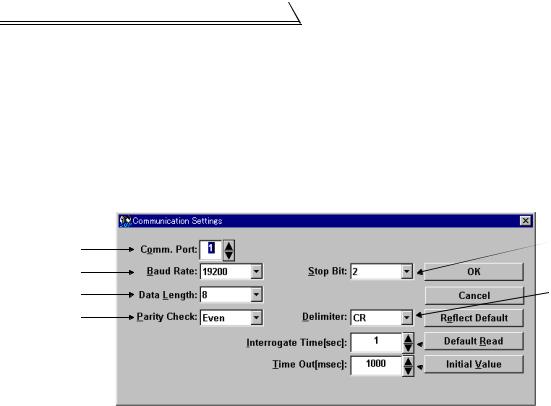
2.2.2Communication Settings
The VFD Setup Software uses the serial port of the personal computer to control the inverters through serial communication. Its communication settings must be the same as those of the inverter. (The initial values of the setup software have been matched with the factory settings of the inverter.)
When you start this software, the initial screen appears. Pressing the [OK] button displays the system setting screen. Choosing the [Settings] → [Communication settings] command on the menu bar. The screen then shows the following dialog box, where various communication settings can be made.
Communication settings will be described below:
5)
1)
2)
3) |
6) |
4)
 7)
7)  8)
8)
(1) Screen explanations
The values in parentheses are initial values.
1)Communication Port (1)
Choose the communication port of the personal computer.
2)Baud Rate (19200)
Set the communication speed.
3)Data Length (8)
Set the data bit length.
4)Parity Check (Even) Specify the parity bit.
5)Stop Bit (2)
Set the stop bit length.
6)Delimiter (CR)
Specify the delimiter at the data trailer.
7)Interrogate Time [sec] (1)
Set the interval at which data transmission (operation mode indication and error check) is always made to the inverter.
8)Time Out [msec] (1000)
Set the time from when data is transferred from the personal computer to the inverter until when the personal computer receives a reply from the inverter. If a reply is not given after the preset time has passed, the "timeout" error is displayed.
The above set values depend on the inverter connected. Set them after confirming the set values of the communication function parameters of the inverter.
(2)Button settings
1)[OK] button
Recognizes the settings on the communication screen and returns to the system setting screen.
2)[Cancel] button
Cancels the communication settings and returns to the system setting screen.
3)[Reflect Default] button
Used to omit the setting of the values specified in communication settings from the next time onward.
4)[Default Read] button
Used to read the default values. The value is as set with the [Reflect Default] button.
5)[Initial Value] button
This button is used to return the communication setting to the initial value (factory setting of the inverter).
12
Settings
(3) Inverter communication settings
The values set for communication depend on the inverter and connection method.
Inverter |
Connection Method |
Operation mode |
Setting Range |
|||
FR-A520(-NA) |
FR-F540 (-NA) |
|
|
|
|
|
FR-A520L |
(-EC) (-CH) |
|
When PU |
|
|
|
FR-A540(-NA) |
FR-F540L (-NA) |
|
|
|
||
(-EC) (-CH) |
(-EC) (-CH) |
|
connector (RS- |
|
|
|
FR-A540L (-NA) |
(-G-CH) (-S-CH) |
PU connector |
485 connector) |
|
|
|
(-G-NA) (-EC) |
FR-F720 (-NA) |
(RS-485 connector) |
is connected PU |
|
|
|
(-G-EC) (-S-EC) |
FR-F740 (-NA) |
or |
mode |
[Node] |
Station 0 to 31 |
|
(-S-CH) |
(-EC) (-CH) |
FR-A5NR |
When FR-A5NR |
|||
[Baud rate] |
4800, 9600, 19200 bps |
|||||
FR-A560-NA |
FR-V520 |
|
is connected |
|||
|
[Stop bit] |
1 bit, 2 bits |
||||
FR-A560L-NA |
FR-V520L |
|
LINK mode |
|||
FR-F520 (-NA) |
FR-V540 |
|
|
[Data length] |
7 bits, 8 bits |
|
FR-F520L |
FR-V540L (-NA) |
|
|
[Parity bit] |
None, odd, even |
|
FR-E520 (-NA) |
FR-E510W (-NA) |
PU connector |
|
[Delimiter] |
None, CR, CR+LF |
|
|
|
|
||||
FR-E520S (-EC) |
FR-E540 (-NA) |
PU mode |
|
|
||
(RS-485 connector) |
|
|
||||
(-CH) |
(-EC) (-CH) |
|
|
|
||
|
|
|
|
|||
FR-S520-R |
FR-S510W-R |
|
|
|
|
|
FR-S520S-R |
FR-S540-R (-NAR) |
RS-485 connector |
LINK mode |
|
|
|
FR-S520S-ECR |
(-ECR) (-CHR) |
|
|
|||
|
|
|
|
|||
(-CHR) |
|
|
|
|
|
|
CAUTION
When making communication with the inverters, set a value other than 0 in Pr. 122 "communication check time interval" on the inverter's operation panel. For the FR-A5NR, set any value other than 0 in Pr. 336 "communication check time interval", and for the FR-S500 series, set any value other than 0 in the communication parameter n6 (336) "communication check time interval".
(Refer to the inverter instruction manual for the setting method.)
(4) Interrogate time
Set the interval at which data is always sent or received to or from the inverter.
It must be set to at least 2 seconds shorter than the communication check time interval setting of the inverter. If its setting is longer than the communication check time interval setting, the inverter will come to an alarm stop.
CAUTION
The setting of short interrogate time may slow down the response of the menus and buttons on each window depending on the operating model and communication speed.
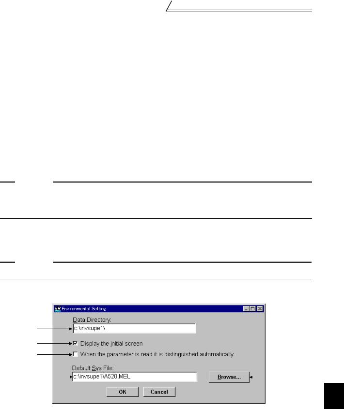
2.2.3Environmental Setting
You can specify the data directory (place where data is saved) and default system file.
1)
2)
5)
|
3) |
|
|
|
|
4) |
|
|
|
|
|||
(1) Screen explanations |
|
|
|
|||
1) |
Data Directory..................................... |
You can change the directory where data will be saved. |
||||
2) |
Display the initial screen..................... |
Checking the check box displays the initial screen. |
||||
3) |
Default Sys File .................................. |
Shows the system file (*.MEL) which is automatically set when |
||||
|
|
|
|
starting of the software. |
||
4) |
Browse |
There is no default registered. |
||||
Default system file browsing button. |
||||||
|
|
|
|
Shows the file selection common dialog and displays the chosen file |
||
5) |
When the parameter is read it is |
name in the default system file text box. |
||||
|
|
|
||||
|
distinguished automatical......................... |
Turn on the check box to hide the parameters read-disabled for parameter |
||||
|
|
|
|
batch-read or batch-verify from the error panel. (Refer to page 16) |
||
2
FUNCTIONS
13
Loading...