


 Loading...
T R A N S I S T O R I Z E
F -SR5 0 0
I N S T R U C T I O N M
W I R CIhNa p
F U N C CThIaOp
P R O T E C T
C h a p
F U N C T I O
U N O U C H I T O K Y O 1 0 0 - 8 3 1 0
S P E C I F CIhC aAp
Thank you for choosing this Mitsubishi Transistorized inverter.
This instruction manual (detailed) provides instructions for advanced use of the FR-S500 series inverters.
Incorrect handling might cause an unexpected fault. Before using the inverter, always read this instruction manual and the instruction manual (basic) [IB-0600026] packed with the product carefully to use the equipment to its optimum.
This instruction manual uses the International System of Units (SI). The measuring units in the yard and pound system are indicated in parentheses as reference values.
This section is specifically about safety matters
Do not attempt to install, operate, maintain or inspect the inverter until you have |
||
read through the instruction manual (basic) and appended documents carefully and |
||
can use the equipment correctly. Do not use the inverter until you have a full |
||
knowledge of the equipment, safety information and instructions. |
||
In this instruction manual, the safety instruction levels are classified into |
||
"WARNING" and "CAUTION". |
||
|
WARNING |
Assumes that incorrect handling may cause hazardous |
|
conditions, resulting in death or severe injury. |
|
|
|
Assumes that incorrect handling may cause hazardous |
|
|
|
|
CAUTION |
|
|
conditions, resulting in medium or slight injury, or may |
|
|
|
cause physical damage only. |
|
|
|
Note that even the CAUTION level may lead to a serious consequence according to |
||
conditions. Please follow the instructions of both levels because they are important |
||
to personnel safety. |
|
|
|
||
1. Electric Shock Prevention |
||
 WARNING
 While power is on or when the inverter is running, do not open the front cover. You may get an electric shock.
 Do not run the inverter with the front cover removed. Otherwise, you may access the exposed high-voltage terminals or the charging part of the circuitry and get an electric shock.
 If power is off, do not remove the front cover except for wiring or periodic inspection. You may access the charged inverter circuits and get an electric shock.
 Before starting wiring or inspection, check for residual voltages with a meter etc. more than 10 minutes after power-off.
 Earth the inverter.
 Any person who is involved in wiring or inspection of this equipment should be fully competent to do the work.
 Always install the inverter before wiring. Otherwise, you may get an electric shock or be injured.
 Perform setting dial and key operations with dry hands to prevent an electric shock.
 Do not subject the cables to scratches, excessive stress, heavy loads or pinching. Otherwise, you may get an electric shock.
 Do not change the cooling fan while power is on.
It is dangerous to change the cooling fan while power is on.
 When you have removed the front cover, do not touch the connector above the 3-digit monitor LED display. You will get an electric shock.
A-1

2. Fire Prevention
 CAUTION
 Mount the inverter to incombustible material. Mounting it to or near combustible material can cause a fire.
 If the inverter has become faulty, switch off the inverter power. A continuous flow of large current could cause a fire.
 Do not connect a resistor directly to the DC terminals P(+ ), N(− ). This could cause a fire.
3. Injury Prevention
 CAUTION
 Apply only the voltage specified in the instruction manual to each terminal to prevent damage etc.
 Ensure that the cables are connected to the correct terminals. Otherwise, damage etc. may occur.
 Always make sure that polarity is correct to prevent damage etc.
 While power is on and for some time after power-off, do not touch the inverter or brake resistor as they are hot and you may get burnt.
4. Additional instructions
Also note the following points to prevent an accidental failure, injury, electric shock, etc.
(1) Transportation and installation
 CAUTION
 When carrying products, use correct lifting gear to prevent injury.
 Do not stack the inverter boxes higher than the number recommended.
 Ensure that installation position and material can withstand the weight of the inverter. Install according to the information in the Instruction Manual.
 Do not operate if the inverter is damaged or has parts missing.
 When carrying the inverter, do not hold it by the front cover or setting dial; it may fall off or fail.
 Do not stand or rest heavy objects on the inverter.
 Check the inverter mounting orientation is correct.
 Prevent screws, wire fragments, other conductive bodies, oil or other flammable substances from entering the inverter.
 Do not drop the inverter, or subject it to impact.
 Use the inverter under the following environmental conditions:
|
|
Ambient |
-10° C to +50° C (14° F to 122° F) (non-freezing) |
|
|
|
temperature |
|
|
|
|
|
|
|
|
|
Ambient humidity |
90%RH or less (non-condensing) |
|
|
Environment |
Storage |
-20° C to +65° C * (-4° F to 149° F) |
|
|
temperature |
|
||
|
|
|
||
|
Ambience |
Indoors (free from corrosive gas, flammable gas, |
|
|
|
oil mist, dust and dirt) |
|
||
|
|
|
||
|
|
Maximum 1000m (3280.80feet) above sea level for |
|
|
|
|
standard operation. After that derate by 3% for |
|
|
|
|
|
|
|
|
|
Altitude, vibration |
every extra 500m (1640.40feet) up to 2500m |
|
|
|
|
(8202.00feet) (91%). |
|
|
|
|
5.9m/s2 or less (conforming to JIS C 0040) |
|
|
*Temperatures applicable for a short time, e.g. in transit. |
|
||
|
|
|
|
|
|
|
|
A-2 |
|

(2) Wiring
 CAUTION
 Do not fit capacitive equipment such as power factor correction capacitor, radio noise filter or surge suppressor to the output of the inverter.
 The connection orientation of the output cables U, V, W to the motor will affect the direction of rotation of the motor.
(3) Trial run
 CAUTION
 Check all parameters, and ensure that the machine will not be damaged by a sudden start-up.
 When the load GD2 is small (at the motor GD2 or smaller) for 400V from 1.5K to 3.7K, the output current may vary when the output frequency is in the 20Hz to 30Hz range.
If this is a problem, set the Pr. 72 "PWM frecuency selection" to 6kHz or higher.
When setting the PWM to a higher frequency, check for noise or leakage current problem and take countermeasures against it.
(4) Operation
 WARNING
 When you have chosen the retry function, stay away from the equipment as it will restart suddenly after an alarm stop.
 The [STOP] key is valid only when the appropriate function setting has been made. Prepare an emergency stop switch separately.
 Make sure that the start signal is off before resetting the inverter alarm. A failure to do so may restart the motor suddenly.
 The load used should be a three-phase induction motor only. Connection of any other electrical equipment to the inverter output may damage the equipment.
  Do not modify the equipment.
 CAUTION
 The electronic overcurrent protection does not guarantee protection of the motor from overheating.
 Do not use a magnetic contactor on the inverter input for frequent starting/stopping of the inverter.
 Use a noise filter to reduce the effect of electromagnetic interference. Otherwise nearby electronic equipment may be affected.
 Take measures to suppress harmonics. Otherwise power harmonics from the inverter may heat/damage the power capacitor and generator.
 When a 400V class motor is inverter-driven, it should be insulation-enhanced or surge voltages suppressed. Surge voltages attributable to the wiring constants may occur at the motor terminals, deteriorating the insulation of the motor.
 When parameter clear or all clear is performed, each parameter returns to the factory setting. Re-set the required parameters before starting operation.
 The inverter can be easily set for high-speed operation. Before changing its setting, fully examine the performances of the motor and machine.
 In addition to the inverter's holding function, install a holding device to ensure safety.
 Before running an inverter which had been stored for a long period, always perform inspection and test operation.
A-3

(6) Maintenance, inspection and parts replacement
 CAUTION
 Do not carry out a megger (insulation resistance) test on the control circuit of the inverter.
(7) Disposing of the inverter
 CAUTION
 Treat as industrial waste.
(8) General instructions
Many of the diagrams and drawings in this instruction manual show the inverter without a cover, or partially open. Never operate the inverter like this. Always replace the cover and follow this instruction manual when operating the inverter.
A-4

CONTENTS |
|
1. WIRING |
1 |
1.1 Japanese Version..................................................................................... |
2 |
1.1.1 Terminal connection diagram .................................................................... |
2 |
1.1.2 Layout and wiring of main circuit terminals............................................... |
3 |
1.2 North America Version ............................................................................. |
4 |
1.2.1 Terminal connection diagram .................................................................... |
4 |
1.2.2 Layout and wiring of main circuit terminals............................................... |
5 |
1.3 European Version..................................................................................... |
7 |
1.3.1 Terminal connection diagram .................................................................... |
7 |
1.3.2 Layout and wiring of main circuit terminals............................................... |
8 |
1.4 Description of I/O Terminal Specifications ............................................... |
9 |
1.4.1 Main circuit .................................................................................................. |
9 |
1.4.2 Control circuit .............................................................................................. |
9 |
1.5 How to Use the Main Circuit Terminals.................................................. |
11 |
1.5.1 Cables, wiring lengths, crimping terminals, etc. ..................................... |
11 |
1.5.2 Wiring instructions .................................................................................... |
12 |
1.5.3 Peripheral devices .................................................................................... |
13 |
1.5.4 Leakage current and installation of earth leakage circuit breaker...... |
15 |
1.5.5 Power-off and magnetic contactor (MC) ................................................. |
17 |
1.5.6 Regarding the installation of the power factor improving reactor ....... |
18 |
1.5.7 Regarding noise and the installation of a noise filter.............................. |
18 |
1.5.8 Grounding precautions............................................................................. |
19 |
1.5.9 Regarding power harmonics..................................................................... |
20 |
1.5.10 Japanese power harmonic suppression guideline............................... |
20 |
1.6 How to Use the Control Circuit Terminals .............................................. |
24 |
1.6.1 Terminal block layout................................................................................ |
24 |
1.6.2 Wiring instructions .................................................................................... |
24 |
1.6.3 Changing the control logic........................................................................ |
25 |
1.7 Input Terminals....................................................................................... |
28 |
1.7.1 Run (start) and stop (STF, STR, STOP)................................................. |
28 |
1.7.2 Connection of frequency setting potentiometer and output frequency |
|
meter (10, 2, 5, 4, AU).............................................................................. |
31 |
1.7.3 External frequency selection (REX, RH, RM, RL).................................. |
32 |
1.7.4 Indicator connection and adjustment ...................................................... |
34 |
1.7.5 Control circuit common terminals (SD, 5, SE)........................................ |
37 |
1.7.6 Signal inputs by contactless switches..................................................... |
37 |
1.8 How to Use the Input Signals |
|
(Assigned Terminals RL, RM, RH, STR)................................................ |
38 |
1.8.1 Multi-speed setting (RL, RM, RH, REX signals): Setting "0, 1, 2, 8" |
|
Remote setting (RL, RM, RH signals): Setting "0, 1, 2"......................... |
38 |
1.8.2 Second function selection (RT signal): Setting "3"................................. |
38 |
I |
|
Contents
1.8.3 Current input selection "AU signal": Setting "4"...................................... |
|
38 |
|
1.8.4 Start self-holding selection (STOP signal): Setting "5"........................... |
|
38 |
|
1.8.5 Output shut-off (MRS signal): Setting "6"................................................ |
|
39 |
|
1.8.6 External thermal relay input: Setting "7".................................................. |
|
39 |
|
1.8.7 Jog operation (JOG signal): Setting "9" .................................................. |
|
40 |
|
1.8.8 Reset signal: Setting "10"......................................................................... |
|
40 |
|
1.8.9 PID control valid terminal: Setting "14".................................................... |
|
41 |
|
1.8.10 PU operation/external operation switching: Setting "16" ..................... |
|
41 |
|
1.9 Handling of the RS-485 Connector |
|
|
|
(Type with RS-485 Communication Function) ....................................... |
|
41 |
|
1.10 Design Information ............................................................................... |
|
|
44 |
2. FUNCTIONS |
|
|
45 |
2.1 Function (Parameter) List....................................................................... |
|
|
46 |
2.2 List of Parameters Classified by Purpose of Use................................... |
|
56 |
|
2.3 Explanation of Functions (Parameters).................................................. |
|
58 |
|
2.3.1 Torque boost |
........................................................................... |
|
58 |
2.3.2 Maximum and minimum frequency ....................................... |
|
59 |
|
2.3.3 Base frequency, Base frequency voltage .................... |
|
59 |
|
2.3.4 Multi-speed operation |
to |
to |
....... 61 |
2.3.5 Acceleration/deceleration time |
................... |
62 |
|
2.3.6 Electronic overcurrent protection .................................................... |
|
64 |
|
2.3.7 DC injection brake |
......................................................... |
|
64 |
2.3.8 Starting frequency |
........................................................................... |
|
65 |
2.3.9 Load pattern selection |
..................................................................... |
|
66 |
2.3.10 Jog frequency |
....................................................................... |
|
67 |
2.3.11 RUN key rotation direction selection ............................................. |
|
67 |
|
2.3.12 Stall prevention function and current limit function ...................... |
|
68 |
|
2.3.13 Stall prevention |
............................................................ |
|
69 |
2.3.14 Acceleration/deceleration pattern ................................................. |
|
71 |
|
2.3.15 Extended function display selection ............................................. |
|
72 |
|
2.3.16 Frequency jump |
to ............................................................... |
|
72 |
2.3.17 Speed display ................................................................................ |
|
|
73 |
2.3.18 Biases and gains of the frequency setting voltage (current) |
|
||
to |
.......................................................................... |
|
74 |
2.3.19 Start-time ground fault detection selection .................................. |
|
78 |
|
2.4 Output Terminal Function Parameters................................................... |
|
78 |
|
2.4.1 Up-to-frequency sensitivity .............................................................. |
|
78 |
|
2.4.2 Output frequency detection .................................................... |
|
79 |
|
2.5 Current Detection Function Parameters................................................. |
|
80 |
|
2.5.1 Output current detection functions ........................................ |
|
80 |
|
2.5.2 Zero current detection |
............................................................ |
|
81 |
2.6 Display Function Parameters ................................................................. |
|
82 |
|
2.6.1 Monitor display |
........................................................................ |
|
82 |
|
II |
|
|

2.6.2 Setting dial function selection |
|
|
|
|
|
|
......................................................... |
|
|
|
|
|
|
|
|
|
|
|
|
|
|
|
|
|
|
|
|
83 |
|||||||||||||||
|
|
|
|
|
|
|
|
|
|
|
|
|
|
|
|
|
|
|
|
|
|
|
|
|
|
|
|
|
|
|
|
|
|
|
|
|
|
|
|
|
|
|
|
2.6.3 Monitoring reference |
|
|
|
|
|
|
|
|
|
|
|
.............................................................. |
|
|
|
|
|
|
|
|
|
|
|
|
|
|
|
|
|
|
|
|
|
|
|
|
84 |
||||||
2.7 Restart Operation Parameters ............................................................... |
|
|
|
|
|
|
|
|
|
|
|
|
|
|
|
|
|
|
|
|
|
|
|
|
|
|
|
84 |
|||||||||||||||
2.7.1 Restart setting |
|
|
|
|
|
|
|
|
|
......................................................................... |
|
|
|
|
|
|
|
|
|
|
|
|
|
|
|
|
|
|
|
|
|
|
|
|
|
|
|
|
|
|
|
84 |
|
2.8 Additional Function Parameters ............................................................. |
|
|
|
|
|
|
|
|
|
|
|
|
|
|
|
|
|
|
|
|
|
|
|
|
|
|
|
86 |
|||||||||||||||
2.8.1 Remote setting function selection |
|
|
|
|
|
|
|
.................................................. |
|
|
|
|
|
|
|
|
|
|
|
|
|
86 |
|||||||||||||||||||||
2.9 Terminal Function Selection Parameters |
|
|
|
|
|
|
|
|
|
|
|
|
|
|
|
88 |
|||||||||||||||||||||||||||
2.9.1 Input terminal function selection |
|
|
|
|
|
|
|
|
|
|
|
|
|
|
|
|
|
|
|
|
|
|
|
.......................... |
88 |
||||||||||||||||||
|
|
|
|
|
|
|
|
|
|
|
|
|
|
|
|
|
|
|
|
|
|
|
|
|
|
|
|
|
|
|
|
|
|
|
|
|
|
|
|
|
|
||
2.9.2 Output terminal function selection |
|
|
|
|
|
|
|
|
|
|
|
|
|
|
......................................... |
|
|
|
|
|
|
90 |
|||||||||||||||||||||
2.10 Operation Selection Function Parameters ........................................... |
|
|
|
|
|
|
|
|
|
|
|
91 |
|||||||||||||||||||||||||||||||
2.10.1 Retry function |
|
|
|
|
|
|
|
|
|
|
|
|
|
|
|
|
|
|
|
|
|
|
|
|
..................................................... |
|
|
|
|
|
|
|
|
|
|
|
|
|
|
|
|
91 |
|
2.10.2 PWM carrier frequency |
|
|
|
|
|
|
|
|
|
|
|
|
|
........................................................ |
|
|
|
|
|
|
|
|
|
|
|
|
|
|
|
|
|
|
92 |
||||||||||
|
|
|
|
|
|
|
|
|
|
|
|
|
|
|
|
|
|
|
|
|
|
|
|
|
|
|
|
|
|
|
|
|
|
|
|
|
|
|
|
|
|
|
|
2.10.3 Applied motor |
|
|
|
|
................................................................................. |
|
|
|
|
|
|
|
|
|
|
|
|
|
|
|
|
|
|
|
|
|
|
|
|
|
|
|
|
|
|
|
|
|
|
|
|
93 |
|
|
|
|
|
|
|
|
|
|
|
|
|
|
|
|
|
|
|
|
|
|
|
|
|
|
|
|
|
|
|
|
|
|
|
|
|
|
|
|
|||||
2.10.4 Voltage input selection |
|
|
|
|
|
.................................................................. |
|
|
|
|
|
|
|
|
|
|
|
|
|
|
|
|
|
|
|
|
|
|
|
|
|
|
|
93 |
|||||||||
|
|
|
|
|
|
|
|
|
|
|
|
|
|
|
|
|
|
|
|
|
|
|
|
|
|
|
|
|
|
|
|
|
|
|
|
|
|
|
|||||
2.10.5 Input filter time constant |
|
|
|
|
|
................................................................ |
|
|
|
|
|
|
|
|
|
|
|
|
|
|
|
|
|
|
|
|
|
|
|
|
|
94 |
|||||||||||
|
|
|
|
|
|
|
|
|
|
|
|
|
|
|
|
|
|
|
|
|
|
|
|
|
|
|
|
|
|
|
|
|
|
|
|
||||||||
2.10.6 Reset selection/PU stop selection |
|
|
|
|
|
|
................................................ |
|
|
|
|
|
|
|
|
|
|
|
94 |
||||||||||||||||||||||||
|
|
|
|
|
|
|
|
|
|
|
|
|
|
|
|
|
|
|
|
|
|
|
|
|
|
|
|
|
|
|
|
|
|
||||||||||
2.10.7 Cooling fan operation selection |
|
|
|
|
|
.................................................... |
|
|
|
|
|
|
|
|
|
|
|
|
|
|
|
96 |
|||||||||||||||||||||
2.10.8 Parameter write inhibit selection |
|
|
|
|
.................................................. |
|
|
|
|
|
|
|
|
|
|
|
|
|
97 |
||||||||||||||||||||||||
2.10.9 Reverse rotation prevention selection |
|
|
|
|
|
|
|
|
|
|
|
|
|
|
|
98 |
|||||||||||||||||||||||||||
|
|
|
|
|
|
.......................................... |
|
|
|
|
|
|
|
|
|||||||||||||||||||||||||||||
|
|
|
|
|
|
|
|
|
|
|
|
|
|
|
|
|
|
|
|
|
|
|
|
|
|
|
|
|
|
|
|
|
|
|
|
|
|
||||||
2.10.10 Operation mode selection |
|
|
|
|
|
........................................................... |
|
|
|
|
|
|
|
|
|
|
|
|
|
|
|
|
|
|
|
|
|
|
98 |
||||||||||||||
|
|
|
|
|
|
|
|
|
|
|
|
|
|
|
|
|
|
|
|
|
|
|
|
|
|
|
|
|
|
|
|
|
|
|
|
|
|
||||||
2.10.11 PID control |
|
|
to |
|
|
|
|
.................................................................... |
|
|
|
|
|
|
|
|
|
|
|
|
|
|
|
|
|
|
|
|
|
|
|
|
|
|
|
|
101 |
||||||
2.11 Auxiliary Function Parameters ........................................................... |
|
|
|
|
|
|
|
|
|
|
|
|
|
|
|
|
|
|
|
|
|
|
|
|
|
|
|
109 |
|||||||||||||||
2.11.1 Slip compensation |
|
|
|
|
|
|
|
|
|
|
|
|
|
|
|
|
..................................................... |
|
|
|
|
|
|
|
|
|
|
|
|
|
|
|
|
|
109 |
||||||||
2.11.2 Automatic torque boost selection |
|
|
|
............................................... |
|
|
|
|
|
|
|
|
|
|
|
|
109 |
||||||||||||||||||||||||||
|
|
|
|
|
|
|
|
|
|
|
|
|
|
|
|
|
|
|
|
|
|
|
|
|
|
|
|
|
|
|
|
|
|
|
|
||||||||
2.11.3 Motor primary resistance |
|
|
|
|
............................................................ |
|
|
|
|
|
|
|
|
|
|
|
|
|
|
|
|
|
|
|
|
|
|
|
|
111 |
|||||||||||||
2.12 Calibration Parameters ...................................................................... |
|
|
|
|
|
|
|
|
|
|
|
|
|
|
|
|
|
|
|
|
|
|
|
|
|
|
|
111 |
|||||||||||||||
2.12.1 Meter (frequency meter) calibration |
|
|
|
|
|
(Japanese version)......... |
111 |
||||||||||||||||||||||||||||||||||||
|
|
|
|
|
|||||||||||||||||||||||||||||||||||||||
2.12.2 Meter (frequency meter) calibration |
|
|
|
|
|
(NA and EC version) ...... |
113 |
||||||||||||||||||||||||||||||||||||
...............................................................................2.13 Clear Parameters |
|
|
|
|
|
|
|
|
|
|
|
|
|
|
|
|
|
|
|
|
|
|
|
|
|
|
|
|
|
|
|
|
|
|
|
|
|
|
|
115 |
|||
2.13.1 Parameter clear |
|
|
|
|
|
........................................................................... |
|
|
|
|
|
|
|
|
|
|
|
|
|
|
|
|
|
|
|
|
|
|
|
|
|
|
|
|
|
|
|
|
|
|
115 |
||
|
|
|
|
|
|
|
|
|
|
|
|
|
|
|
|
|
|
|
|
|
|
|
|
|
|
|
|
|
|
|
|
|
|
||||||||||
2.13.2 Alarm history clear |
|
|
....................................................................... |
|
|
|
|
|
|
|
|
|
|
|
|
|
|
|
|
|
|
|
|
|
|
|
|
|
|
|
|
|
|
115 |
|||||||||
2.14 Communication Parameters |
|
|
|
|
|
|
|
|
|
|
|
|
|
|
|
|
|
|
|
|
|
|
|
|
|
|
|
|
|||||||||||||||
(Only for the type having the RS-485 communication function)........... |
116 |
||||||||||||||||||||||||||||||||||||||||||
2.14.1 Communication settings |
|
|
|
|
to |
|
, |
|
|
|
|
|
|
...................................... 118 |
|||||||||||||||||||||||||||||
2.14.2 Operation and speed command write |
|
|
|
|
|
|
|
|
|
|
|
|
|
|
|
130 |
|||||||||||||||||||||||||||
|
|
|
|
|
|
|
|
|
|
|
|
............................... |
|
|
|||||||||||||||||||||||||||||
2.14.3 Link start mode selection |
|
|
|
|
............................................................ |
|
|
|
|
|
|
|
|
|
|
|
|
|
|
|
|
|
|
|
|
|
|
|
|
131 |
|||||||||||||
2.14.4 E2PROM write selection |
|
|
|
.............................................................. |
|
|
|
|
|
|
|
|
|
|
|
|
|
|
|
|
|
|
|
|
|
|
|
|
|
132 |
|||||||||||||
2.15 Parameter Unit (FR-PU04) Setting .................................................... |
|
|
|
|
|
|
|
|
|
|
|
|
|
|
|
133 |
|||||||||||||||||||||||||||
2.15.1 Parameter unit display language switching |
|
|
|
............................... |
|
133 |
|||||||||||||||||||||||||||||||||||||
|
|
|
|
|
|
|
|
|
|
|
|
|
|
|
|
|
|
|
|
|
|
|
|
|
|
|
|
|
|
||||||||||||||
2.15.2 Buzzer sound control |
|
|
.................................................................. |
|
|
|
|
|
|
|
|
|
|
|
|
|
|
|
|
|
|
|
|
|
|
|
|
|
|
|
133 |
||||||||||||
|
|
|
|
|
|
|
|
|
|
|
|
|
|
|
|
|
|
|
|
|
|
|
|
|
|
|
|
|
|||||||||||||||
2.15.3 PU contrast adjustment |
|
............................................................... |
|
|
|
|
|
|
|
|
|
|
|
|
|
|
|
|
|
|
|
|
|
|
|
|
|
|
134 |
||||||||||||||
2.15.4 PU main display screen data selection |
|
|
|
|
|
|
|
...................................... |
|
|
|
|
134 |
||||||||||||||||||||||||||||||
|
|
||||||||||||||||||||||||||||||||||||||||||
2.15.5 PU disconnection detection/PU setting lock |
|
.............................. |
135 |
||||||||||||||||||||||||||||||||||||||||
III
Contents

3. PROTECTIVE FUNCTIONS |
136 |
|
3.1 |
Errors (Alarms) ..................................................................................... |
137 |
3.1.1 Error (alarm) definitions.......................................................................... |
137 |
|
3.1.2 To know the operating status at the occurrence of alarm |
|
|
|
(Only when FR-PU04 is used)............................................................... |
145 |
3.1.3 Correspondence between digital and actual characters...................... |
145 |
|
3.1.4 Resetting the inverter ............................................................................. |
145 |
|
3.2 |
Troubleshooting.................................................................................... |
146 |
3.2.1 Motor remains stopped .......................................................................... |
146 |
|
3.2.2 Motor rotates in opposite direction ........................................................ |
147 |
|
3.2.3 Speed greatly differs from the setting.................................................... |
147 |
|
3.2.4 Acceleration/deceleration is not smooth ............................................... |
147 |
|
3.2.5 Motor current is large.............................................................................. |
147 |
|
3.2.6 Speed does not increase ....................................................................... |
147 |
|
3.2.7 Speed varies during operation............................................................... |
147 |
|
3.2.8 Operation mode is not changed properly.............................................. |
148 |
|
3.2.9 Operation panel display is not operating............................................... |
148 |
|
3.2.10 Parameter write cannot be performed ................................................ |
148 |
|
3.2.11 Motor produces annoying sound......................................................... |
148 |
|
3.3 |
Precautions for Maintenance and Inspection....................................... |
149 |
3.3.1 Precautions for maintenance and inspection........................................ |
149 |
|
3.3.2 Check items ............................................................................................ |
149 |
|
3.3.3 Periodic inspection.................................................................................. |
149 |
|
3.3.4 Insulation resistance test using megger................................................ |
150 |
|
3.3.5 Pressure test........................................................................................... |
150 |
|
3.3.6 Daily and periodic inspection ................................................................. |
150 |
|
3.3.7 Replacement of parts ............................................................................. |
154 |
|
3.3.8 Measurement of main circuit voltages, currents and powers.............. |
157 |
|
4. SPECIFICATIONS |
160 |
|
4.1 |
Specification List .................................................................................. |
161 |
4.1.1 Ratings .................................................................................................... |
161 |
|
4.1.2 Common specifications.......................................................................... |
165 |
|
4.2 |
Outline Drawings .................................................................................. |
167 |
5. INSTRUCTIONS |
170 |
|
5.1 |
Selecting Instructions ........................................................................... |
171 |
5.2 |
Peripheral Selecting Instructions.......................................................... |
171 |
5.3 |
Operating Instructions .......................................................................... |
173 |
5.4 |
Inverter-driven 400V class motor ......................................................... |
175 |
APPENDIX |
176 |
|
APPENDIX 1 PARAMETER DATA CODE LIST ........................................ |
177 |
|
IV
1. WIRING
This chapter explains the basic "wiring" for use of this product. Always read the instructions before use. For description of "installation", refer to the instruction manual (basic).
1.1 Japanese Version ...................................................... |
2 |
|
1.2 |
North America Version............................................... |
4 |
1.3 European Version ...................................................... |
7 |
|
1.4 |
Description of I/O Terminal specification .................... |
9 |
1.5 |
How to Use the Main Circuit Terminals .................... |
11 |
1.6 |
How to Use the Control Circuit Terminals ................ |
24 |
1.7 |
Input Terminals ........................................................ |
28 |
1.8 |
How to Use the Input Signals |
|
|
(Assigned Terminals RL, RM, RH, STR) .................. |
38 |
1.9 |
Handling of the RS-485 Connector |
|
|
(Type with RS-485 Communication Function) .......... |
41 |
1.10 Design Information................................................. |
44 |
|
<Abbreviations> |
|
|
|
PU |
|
|
Control panel and parameter unit (FR-PU04) |
|
|
Inverter |
|
|
Mitsubishi transistorized inverter FR-S500 series |
|
|
FR-S500 |
|
|
Mitsubishi transistorized inverter FR-S500 series |
|
|
Pr. |
|
|
Parameter number |
|
1
Chapter1
Chapter 2
Chapter 3
Chapter 4
1.1 Japanese Version
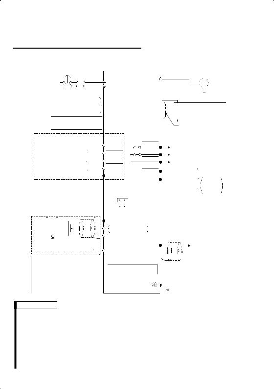
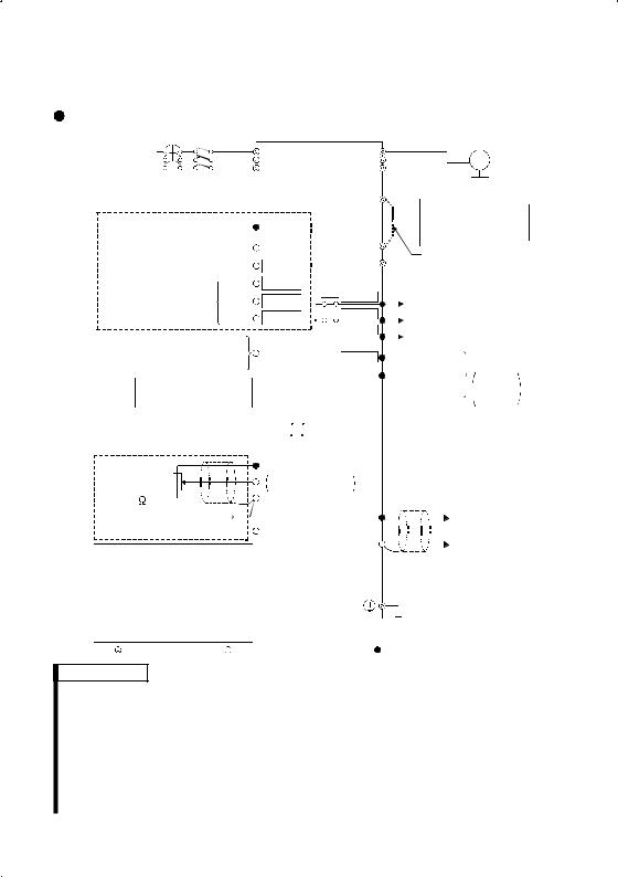
1.1.1 Terminal connection diagram
 FR-S520-0.1K to 3.7K (-R) (-C)
 FR-S540-0.4K to 3.7K (-R)
|
NFB MC |
|
Inverter |
|
3-phase AC |
R |
U |
||
power supply |
S |
V |
||
T |
W |
|||
External transistor common |
||||
|
P1 |
|||
|
24VDC power supply |
PC |
||
|
|
|||
Contact input common (source) |
|
|
||
|
|
|
|
|
|
Be careful not to short |
|
P |
|
|
terminals PC-SD. |
|
||
|
|
N |
||
|
|
|
||
|
Forward rotation start |
STF |
||
|
|
|||
Motor
IM
 Ground
Power factor improving
DC reactor (FR-BEL: Option)
Jumper: Remove this jumper when FR-BEL is connected.
Reverse rotation start |
STR *5 |
*6 |
A |
|
|
|
|||
|
|
High |
RH |
*5 |
*6 |
B |
Alarm |
|
|
Multi-speed selection Middle |
RM |
*5 |
*6 |
C |
output |
|
|
||
|
|
|
|
|
|||||
|
|
Low |
RL |
*5 |
*6RUN |
Running |
|
Operation status |
|
Contact input common |
SD |
|
|
output |
|||||
|
|
SE |
Open collector |
||||||
|
|
Open |
|||||||
|
|
|
(Note) |
|
|||||
Control input signals |
|
SINK |
|
|
output common |
collector |
|||
|
|
|
|
|
outputs |
||||
(No voltage input allowed) |
|
|
|
|
|
|
|||
|
|
(*3) |
|
|
|
|
|||
|
|
|
|
|
|
|
|
|
|
Frequency setting signals (Analog) |
SOURCE |
|
Indicator |
||||||
|
|
|
|
||||||
|
|
|
|
1mA full-scale |
|||||
|
|
|
|
|
|
|
|||
Frequency |
|
3 2 |
10 (+5V) |
|
|
Analog meter |
|||
|
Selected |
|
(Digital indicator) |
||||||
setting |
|
|
2 DC 0 to 5V |
|
|
1mA |
|
||
potentiometer |
1 |
DC 0 to 10V |
|
FM |
|
|
|||
1/2W1k |
|
5 (Common) |
|
(+) |
(-) |
||||
|
|
Calibration |
|||||||
(*4) |
Current input (-) |
|
|
|
|
|
|
||
|
|
|
|
resistor (*2) |
|
||||
|
|
|
|
|
|
||||
4 to 20mADC (+) |
4 (4 to 20mADC) |
|
|
||||||
SD |
|
|
|
||||||
|
|
|
|
|
|
|
|
|
|
When using the current input as |
|
|
|
|
|
the frequency setting signal, set |
|
|
|
|
|
"4" in any of Pr. 60 to Pr. 63 (input |
|
|
|
|
|
RS-485 Connector (*1) |
|
||||
terminal function selection), assign |
|
|
|||
|
|
|
|
|
|
AU (current input selection) to any |
|
|
|
|
Earth (Ground) |
|
|
|
|||
of terminals RH, RM, RL and STR, |
|
|
|
|
|
|
|
|
|
|
|
and turn on the AU signal. |
|
|
|
|
|
|
|
|
|
|
|
|
|
|
|
|
|
 Main circuit terminal
  Control circuit input terminal
  Control circuit output terminal
REMARKS
*1 Only the type with RS-485 communication function.
*2 Not needed when the setting dial is used for calibration. This resistor is used when calibration must be made near the frequency meter for such a reason as a remote frequency meter. Note that the needle of the frequency meter may not deflect to full-scale when the calibration resistor is connected. In this case, use both the resistor and setting dial for calibration.
*3 You can switch between the sink and source logic positions. Refer to page 25. *4 When the setting potentiometer is used frequently, use a 2W1kΩ potentiometer. *5 The terminal functions change with input terminal function selection (Pr. 60 to
Pr. 63). (Refer to page 38, 88) (RES, RL, RM, RH, RT, AU, STOP, MRS, OH, REX, JOG, X14, X16, (STR) signal selection)
*6 The terminal functions change with output terminal function selection (Pr. 64, Pr. 65). (Refer to page 90) (RUN, SU, OL, FU, RY, Y12, Y13, FDN, FUP, RL, LF, ABC signal selection)
2

CAUTION
To prevent a malfunction due to noise, keep the signal cables more than 10cm (3.94inches) away from the power cables.
 FR-S520S-0.1K to 1.5K (-R) (-C)
 FR-S510W-0.1K to 0.75K (-R)
|
NFB MC |
|
Motor |
|||||||||||||||
Power supply |
|
|
|
|
|
|
|
R |
U |
|||||||||
|
|
|
|
|
|
|
S |
V |
|
|
IM |
|||||||
|
|
|
|
|
|
|
|
|
||||||||||
|
|
|
|
|
|
|
|
|
|
|||||||||
|
|
|
|
|
|
|
|
|
W |
|
|
|
|
|
|
|
|
Earth |
|
|
|
|
|
|
|
|
|
|
|
|
|
|
|||||
|
|
|
|
|
|
|
|
|
|
|
|
|
|
|
|
|
|
(Ground) |
|
|
|
|
|
|
|
|
|
|
|
|
|
|
|
|
|
|
|
|
|
|
|
|
|
|
|
|
|
|
|
|
|
|
|
|
|
|
REMARKS
•To ensure safety, connect the power input to the inverter via a magnetic contactor and earth leakage circuit breaker or no-fuse breaker, and use the magnetic contactor to switch power on-off.
•The output is three-phase 200V.
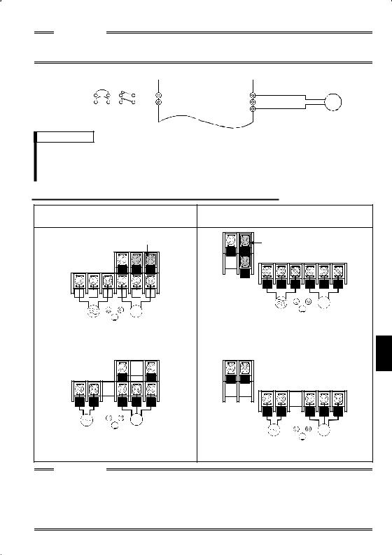
1.1.2 Layout and wiring of main circuit terminals
FR-S520-0.1K, 0.2K, 0.4K, 0.75K (-R) (-C) FR-S520-1.5K, 2.2K, 3.7K (-R) (-C) FR-S540-0.4K, 0.75K, 1.5K, 2.2K, 3.7K (-R)
|
|
|
|
Jumper |
Jumper |
|
|
|
|
||
|
|
|
|
|
|
|
|
|
|
||
|
|
|
|
|
N |
P |
|
|
|
|
|
|
|
|
N |
P1 |
P |
P1 |
|
|
|
|
|
|
|
|
|
|
|
|
|
|
|
|
|
|
|
|
|
|
|
R |
S |
T |
U |
V |
W |
R |
S |
T |
U |
V |
W |
|
|
|
|
|
|
|
|
|
|
|
|
|
|
|
|
IM |
|
IM
 Power supply Motor Power supply Motor
FR-S520S-0.1K, 0.2K, 0.4K, 0.75K (-R) FR-S520S-1.5K (-R)
|
|
|
Jumper |
Jumper |
|
|
|
||
|
|
|
|
|
|
|
|
||
|
|
|
|
N |
P |
|
|
|
|
|
|
N |
P1 |
P |
P1 |
|
|
|
|
|
|
|
|
|
|
|
|
|
|
|
|
|
|
|
R |
S |
U |
V |
W |
R |
S |
U |
V |
W |
|
|
|
|
|
|
|
|
|
|
|
IM |
1 |
|
|
IM |
|||||
|
|
|
|
|
|||
|
|
|
|
|
|||
|
|
Power supply Motor |
|||||
|
|
|
|
|
|||
|
|
|
|
|
|||
Power supply Motor |
|
|
|
|
|||
FR-S510W-0.1K, 0.2K, 0.4K (-R) |
FR-S510W-0.75K (-R) |
|
|||||
|
|
N |
|
P |
N |
P |
|
|
|
|
R |
S |
U |
V |
W |
|
|
|
|
|
|
|
|
|
|
|
|
R |
S |
U |
V |
W |
|
|
|
IM |
|
|
|
|
|
|
|
Power supply |
|
Motor |
|
IM |
|
||||
|
|
|
||
|
|
Power supply |
|
Motor |
|
|
|
CAUTION
•The power supply cables must be connected to R, S, T. If they are connected to U, V, W, the inverter will be damaged. (Phase sequence need not be matched.)
For use with a single-phase power supply, the power supply cables must be connected to R and S.
•Connect the motor to U, V, W.
Turning on the forward rotation switch (signal) at this time rotates the motor counterclockwise when viewed from the load shaft.
3
1.2 North America Version
1.2.1 Terminal connection diagram
 FR-S520-0.1K to 3.7K-NA
 FR-S540-0.4K to 3.7K-NA (R)
Inverter
NFB MC
3-phase AC 


 R
R
power supply S T
External transistor common 24VDC power supply  PC
PC
Contact input common (source)
Take care not to short terminals PC-SD.
Forward rotation start STF
STF
U
V
W
P1

P
N
Motor
IM
 Earth
Earth
(Ground)
Power factor improving DC reactor
(FR-BEL: Option)
Jumper: Remove this jumper when FR-BEL is connected.
Reverse rotation start |
STR *4 |
|
|
*5 |
A |
|
|
|
|
||||||||
|
|
|
|
|
|
High |
RH |
*4 |
|
|
*5 |
B |
|
Alarm |
|
||
Multi-speed selection Middle |
RM |
*4 |
|
|
*5 |
C |
|
output |
|
||||||||
|
|
|
|
|
|
|
|
|
|||||||||
|
|
|
|
|
|
Low |
RL |
*4 |
|
|
*5RUN |
Running |
Operation status |
||||
Contact input common |
SD |
|
|
|
output |
||||||||||||
|
|
|
|
SE |
|
|
|
||||||||||
|
|
|
|
Open collector |
Open |
||||||||||||
Control input signals |
|
|
|
|
|
||||||||||||
|
|
|
|
|
|
|
output common |
collector |
|||||||||
(No voltage input allowed) |
|
SINK |
|
|
|
|
|
|
outputs |
||||||||
|
|
|
|
|
|
|
|
|
|
|
|
|
|
|
|||
|
|
|
|
|
|
|
|
(*2) |
|
|
|
|
|
|
|
|
|
Frequency setting signals (Analog) |
SOURCE |
|
|
|
|
|
|
|
|||||||||
Frequency |
|
3 |
2 |
|
|
10 (+5V) |
|
|
|
|
|
|
|
||||
|
|
|
|
|
|
|
|
|
|
||||||||
|
|
|
|
|
|
|
|
|
|
||||||||
|
|
|
|
|
|
|
|
|
|
||||||||
|
|
|
|
|
|
|
|
|
|
||||||||
setting |
|
|
|
|
|
DC 0 to 5V |
|
|
|
|
|
|
|
||||
|
|
|
|
|
|
|
|
|
|
||||||||
|
|
|
|
|
|
|
|
|
|
|
|||||||
|
|
|
|
|
|
|
|
|
|
||||||||
|
|
|
|
|
|
|
|
|
|
||||||||
|
|
|
|
|
|
|
|
|
|
||||||||
potentiometer |
|
|
|
|
|
2 DC 0 to 10V Selected |
|
|
|
|
|
|
|||||
|
|
|
|
|
|
|
|
|
|
|
|||||||
|
|
|
|
|
|
|
|
|
|
|
|||||||
|
|
|
|
|
|
|
|
|
|
|
|||||||
|
|
|
|
|
|
|
|
|
|
|
|||||||
1 |
|
|
|
|
|
|
|
|
|
||||||||
1/2W1k |
|
|
|
|
5 (Common) |
|
|
|
|
|
|
|
|||||
|
|
|
|
|
|
|
|
|
|
||||||||
|
|
|
|
|
|
|
|
|
|
||||||||
|
|
|
|
|
|
|
|
|
|
||||||||
|
|
|
|
|
|
|
|
|
|
||||||||
|
|
|
|
|
|
|
|
|
|
||||||||
(*3) |
Current input (-) |
|
|
|
|
|
AM |
|
|
|
(+) Analog signal |
||||||
4 to 20mADC (+) |
4 (4 to 20mADC) |
|
|
|
|
||||||||||||
|
|
|
|
|
|
output |
|||||||||||
When using the current input as the frequency setting signal, set "4" in any of Pr. 60 to Pr. 63 (input terminal function selection), assign AU (current input selection) to any of terminals RH, RM, RL and STR, and turn on the AU signal.
5


 (-) (0 to 5VDC)
RS-485 Connector (*1)
Earth (Ground)
 Main circuit terminal
  Control circuit input terminal
  Control circuit output terminal
REMARKS
*1 Only the type with RS-485 communication function.
*2 You can switch between the sink and source logic positions. Refer to page 25. *3 When the setting potentiometer is used frequently, use a 2W 1kΩ potentiometer. *4 The terminal functions change with input terminal function selection (Pr. 60 to
Pr. 63). (Refer to page 38, 88) (RES, RL, RM, RH, RT, AU, STOP, MRS, OH, REX, JOG, X14, X16, (STR) signal selection)
*5 The terminal functions change with output terminal function selection (Pr. 64, Pr. 65). (Refer to page 90) (RUN, SU, OL, FU, RY, Y12, Y13, FDN, FUP, RL, LF, ABC signal selection)
4
NOTE
To prevent a malfunction due to noise, keep the signal cables more than 10cm (3.94inches) away from the power cables.
 FR-S510W-0.1K to 0.75K-NA
|
NFB MC |
|
Motor |
|||||||||||||||
Power supply |
|
|
|
|
|
|
|
R |
U |
|||||||||
|
|
|
|
|
|
|
S |
V |
|
|
IM |
|||||||
|
|
|
|
|
|
|
|
|
||||||||||
|
|
|
|
|
|
|
|
|
|
|||||||||
|
|
|
|
|
|
|
|
|
W |
|
|
|
|
|
|
|
|
Earth |
|
|
|
|
|
|
|
|
|
|
|
|
|
|
|
|
|
||
|
|
|
|
|
|
|
|
|
|
|
|
|
|
|
|
|
|
|
|
|
|
|
|
|
|
|
|
|
|
|
|
|
|
|
|
|
|
|
|
|
|
|
|
|
|
|
|
|
|
|
|
|
|
|
|
(Ground) |
REMARKS
•To ensure safety, connect the power input to the inverter via a magnetic contactor and earth leakage circuit breaker or no-fuse breaker, and use the magnetic contactor to switch power on-off.
•The output is three-phase 200V.
1.2.2 Layout and wiring of main circuit terminals
FR-S520-0.1K, 0.2K, 0.4K, 0.75K-NA |
FR-S520-1.5K, 2.2K, 3.7K-NA |
|
FR-S540-0.4K, 0.75K, 1.5K, 2.2K, 3.7K-NA (R) |
||
|
|
Jumper |
Jumper |
|
|
|
|
||
|
|
|
|
|
|
|
||
|
|
N |
P |
|
|
|
|
|
N |
P1 |
P |
P1 |
|
|
|
|
|
|
|
|
|
|
|
|
|
|
|
|
|
R |
S |
T |
U |
V |
W |
|
R |
|
S |
|
T |
|
|
|
U |
|
V |
|
W |
|
|
|
|
|
|
|
|
|
||
|
|
|
|
|
|
|
|
|
|
|
|
|
|
|
|
|
|
|
|
|
|
IM |
||
|
|
|
|
|
|
|
|
|
|
|
|
IM |
Power |
|
|
|
Motor |
|||||||
|
|
|
|
|
|
|
|
|
|
|
|
|
|
|
||||||||||
|
Power |
|
|
|
|
Motor |
supply |
|
|
|
|
|
|
|||||||||||
|
supply |
|
|
|
|
|
|
|
|
|
|
|
|
|
|
|
|
|
|
|||||
|
|
|
|
|
|
|
|
|||||||||||||||||
FR-S510W-0.1K, 0.2K, 0.4K-NA |
FR-S510W-0.75K-NA |
|
|
|
|
|
1 |
|||||||||||||||||
|
|
|
|
|
|
|
|
|
|
|
|
|
|
|
|
|
|
|
|
|||||
|
|
N |
|
P |
N |
P |
|
|
|
|
R |
S |
U |
V |
W |
|
|
|
|
|
|
|
|
|
|
|
|
R |
S |
U |
V |
W |
IM
Power |
|
|
Motor |
|
|
|
|
IM |
|
|
|
|
|
|
|||
supply |
|
|
|
Power |
|
|
|
Motor |
|
|
|
|
supply |
|
|
|
|
CAUTION
•The power supply cables must be connected to R, S, T. If they are connected to U, V, W, the inverter will be damaged. (Phase sequence need not be matched.)
•Connect the motor to U, V, W.
Turning on the forward rotation switch (signal) at this time rotates the motor counterclockwise when viewed from the load shaft.
5

<When single-phase power input is provided for three-phase power input inverter (NA version only)>
 Reduce the output current.
FR-S520- K-NA inverter |
0.1 |
0.2 |
0.4 |
0.75 |
1.5 |
2.2 |
3.7 |
Rated output current (A) |
0.4 |
0.8 |
1.5 |
2.5 |
4.0 |
5.0 |
7.0 |
Power supply capacity (kVA) |
0.4 |
0.8 |
1.5 |
2.5 |
4.5 |
5.5 |
9.0 |
AC input current (A) |
1.1 |
2.4 |
4.5 |
6.4 |
11.2 |
12.9 |
17.4 |
 Set m9 (Pr. 637) "current detection filter".
Setting "801" in the manufacturer setting parameter C8 enables you to set the m9 parameter.
CAUTION
Parameters other than m9 can also be made to be displayed, but never alter these since they are manufacturer setting parameters.
m9 Setting |
Description |
|
0 |
Single-phase power input |
|
- - - |
Three-phase power input |
|
(Factory setting) |
||
|
CAUTION
Always return the C8 parameter to 0 (factory setting) after you have finished the setting of m9.
6
1.3 European Version
1.3.1 Terminal connection diagram
|
|
|
|
|
|
|
|
|
|
|
|
|
|
|
|
|
|
|
|
|
|
|
|
|
|
|
|
|
|
|
|
|
|
|
|
FR-S540-0.4K to 3.7K-EC(R) |
|
|
Inverter |
|
|
|
|
|
|
|
|
|
|
|
|
|
|
|
|||||||||||||
|
|
|
|
|
NFB MC |
|
|
|
|
|
|
|
|
|
|
|
|
|
|
Motor |
|||||||||||||
|
|
3-phase AC |
|
|
|
|
|
|
|
|
|
L1 |
|
|
|
|
|
|
U |
|
|
|
|
|
|||||||||
|
|
|
|
|
|
|
|
|
|
|
|
|
|
|
|
|
|
|
|
|
|
IM |
|||||||||||
|
|
power supply |
|
|
|
|
|
|
|
|
L2 |
|
|
|
|
|
|
V |
|
|
|
|
|
||||||||||
|
|
|
|
|
|
|
|
|
|
L3 |
|
|
|
|
|
W |
|
|
|
|
|
|
|
|
|||||||||
|
|
|
|
|
|
|
|
|
|
|
|
|
|
|
|
|
|
|
|
|
|
|
|
Earth |
|||||||||
|
|
|
Control input signals |
|
|
|
|
|
|
|
|
|
|
|
|
|
|
|
|
|
|
||||||||||||
|
|
|
|
|
|
|
|
|
|
|
|
|
|
|
|
|
|
|
|
|
(Ground) |
||||||||||||
|
|
|
(No voltage input allowed) |
|
|
|
|
|
|
|
P1 |
|
|
|
|
|
|||||||||||||||||
|
|
|
|
|
|
|
|
|
|
|
|
|
|
|
|
|
|
||||||||||||||||
|
|
|
|
|
|
|
|
|
|
|
Power factor improving |
|
|
||||||||||||||||||||
|
|
|
|
|
|
|
|
|
|
|
|
|
|
|
|
|
|
|
|
|
|
|
|
|
|
|
|
|
|
||||
|
|
|
|
Contact input common |
|
PC |
|
|
|
|
|
|
|
|
|
|
|
|
|
|
DC reactor |
|
|||||||||||
|
|
|
|
|
|
|
|
|
|
|
|
|
|
|
|
|
|
|
(FR-BEL: Option) |
|
|
||||||||||||
|
|
|
|
|
|
|
|
|
|
|
|
|
|
|
|
|
|
|
|
|
|
|
|
|
|
|
|
|
|
||||
|
|
|
|
Forward rotation start |
STF |
|
|
|
|
|
|
|
|
|
|
|
|
|
|
|
|
|
|
|
|||||||||
|
|
|
|
|
|
|
|
|
|
|
|
|
|
|
|
Jumper: Remove this |
|||||||||||||||||
|
|
|
|
|
|
|
|
|
|
|
|
|
|
|
|
||||||||||||||||||
|
|
|
|
|
|
|
|
|
|
|
|
|
|
|
|
|
|
|
|
|
|
|
|
|
|
|
|
|
|||||
|
|
|
|
Reverse rotation start |
STR |
*4 |
|
|
|
|
|
|
|
|
|
|
|
|
|
jumper when FR-BEL |
|||||||||||||
|
|
|
|
|
|
|
|
|
|
|
|
|
|
|
|||||||||||||||||||
|
|
|
|
|
|
|
|
|
|
High |
RH |
*4 |
|
|
|
|
|
|
|
|
|
|
|
|
|
is connected. |
|||||||
|
|
|
|
|
|
|
|
|
|
|
|
|
|
|
|
|
|
|
|
|
|
|
|
|
|
|
|
||||||
|
|
|
Multi-speed selection Middle |
RM |
*4 |
|
|
*5 |
|
A |
|
|
|
|
|
|
|
|
|||||||||||||||
|
|
|
|
|
|
|
|
|
|
Low |
RL |
*4 |
|
|
*5 |
|
B |
|
|
Alarm |
|
|
|
||||||||||
|
|
|
|
|
|
|
|
|
|
*5 |
|
C |
|
|
output |
|
|
|
|||||||||||||||
|
|
|
External transistor common |
|
|
|
|
|
|
|
|
|
|||||||||||||||||||||
|
|
|
|
|
|
|
|
|
|
|
|
|
|
|
|
|
|
|
|
|
|
|
|
||||||||||
|
|
|
|
24VDC power supply |
SD |
|
|
|
*5RUN |
|
Running |
Operation status |
|||||||||||||||||||||
|
|
|
Contact input common (sink) |
|
|
|
|
|
|
output |
|||||||||||||||||||||||
|
|
|
|
|
|
|
|
|
SE |
|
|
|
|
|
|||||||||||||||||||
|
|
|
|
|
|
|
|
|
|
|
|
|
|
|
|
|
|
|
|
Open collector |
Open |
||||||||||||
|
|
|
|
Take care not to short |
|
|
|
|
|
|
|
|
|
||||||||||||||||||||
|
|
|
|
|
|
|
|
|
|
|
|
|
|
|
|
|
|
|
output common |
collector |
|||||||||||||
|
|
|
|
terminals PC-SD. |
|
|
|
|
|
|
|
|
|
|
|
|
|
|
|
|
|
|
|
outputs |
|||||||||
|
|
|
|
|
|
|
|
|
|
|
|
|
|
|
|
|
|
|
|
|
|
|
|
|
|
|
|
|
|
|
|||
|
|
|
|
|
|
|
|
|
|
|
|
|
|
SINK |
|
|
|
|
|
|
|
|
|
|
|
|
|
|
|
|
|
|
|
|
|
|
|
|
|
|
|
|
|
|
|
|
|
|
|
(*2) |
|
|
|
|
|
|
|
|
|
|
|
|
|
|
|
|
|
|
|
Frequency setting signals (Analog) |
|
SOURCE |
|
|
|
|
|
|
|
|
|
|
|
|
|
|
|
||||||||||||||
|
|
|
Frequency |
|
3 2 |
|
|
|
|
10 (+5V) |
|
|
|
|
|
|
|
|
|
|
|
|
|
|
|
|
|
|
|||||
|
|
|
|
|
|
|
|
|
|
|
|
|
|
|
|
|
|
|
|
|
|
|
|
|
|||||||||
|
|
|
|
|
|
|
|
|
|
|
|
|
|
|
|
|
|
|
|
|
|
|
|
|
|||||||||
|
|
|
|
|
|
|
|
|
|
|
|
|
|
|
|
|
|
|
|
|
|
|
|
|
|||||||||
|
|
|
|
|
|
|
|
|
|
|
|
|
|
|
|
|
|
|
|
|
|
|
|
|
|||||||||
|
|
|
|
|
|
|
|
|
|
|
|
|
|
|
|
|
|
|
|
|
|
|
|
|
|||||||||
|
|
|
setting |
|
|
|
|
|
|
|
|
2 DC 0 to 5V |
Selected |
|
|
|
|
|
|
|
|
|
|
|
|
|
|
|
|||||
|
|
|
|
|
|
|
|
|
|
|
|
|
|
|
|
|
|
|
|
|
|
|
|
|
|||||||||
|
|
|
|
|
|
|
|
|
|
|
|
|
|
|
|
|
|
|
|
|
|
|
|
|
|||||||||
|
|
|
|
|
|
|
|
|
|
|
|
|
|
|
|
|
|
|
|
|
|
|
|
|
|||||||||
|
|
|
|
|
|
|
|
|
|
|
|
|
|
|
|
|
|
|
|
|
|
|
|
|
|||||||||
|
|
|
|
|
|
|
|
|
|
|
|
|
|
|
|
|
|
|
|
|
|
|
|
|
|||||||||
|
|
|
|
|
|
|
|
|
|
|
|
|
|
|
|
|
|
|
|
|
|
|
|
|
|||||||||
|
|
|
potentiometer |
|
|
|
|
|
|
|
|
|
|
|
|
|
|
|
|
|
|
|
|
|
|
||||||||
|
|
|
|
|
|
|
|
|
|
|
DC 0 to 10V |
|
|
|
|
|
|
|
|
|
|
|
|
|
|
|
|
|
|
||||
|
|
1 |
|
|
|
|
|
|
|
|
|
|
|
|
|
|
|
|
|
|
|
|
|
|
|
||||||||
|
|
|
1/2W1k |
|
|
|
|
|
|
5 (Common) |
|
|
|
|
|
|
|
|
|
|
|
|
|
|
|
||||||||
|
|
|
|
|
|
|
|
|
|
|
|
|
|
|
|
|
|
|
|
|
|
|
|||||||||||
|
|
|
|
|
|
|
|
|
|
|
|
|
|
|
|
|
|
|
|
|
|
||||||||||||
|
|
|
|
|
|
|
|
|
|
|
|
|
|
|
|
|
|
|
|
|
|
||||||||||||
|
|
|
|
|
|
|
|
|
|
|
|
|
|
|
|
|
|
|
|
|
|
||||||||||||
|
|
|
|
|
|
|
|
|
|
|
|
|
|
|
|
|
|
|
|
|
|
||||||||||||
(*3) |
|
Current input (-) |
|
|
|
|
|
|
AM |
|
|
|
|
(+) Analog signal |
|||||||||||||||||||
|
|
|
|
|
|
|
|
|
|
|
|
|
|
|
|||||||||||||||||||
|
|
|
|
4 to 20mADC (+) |
4 (4 to 20mADC) |
|
|
|
|
|
|
|
|
|
|
|
|
output |
|
||||||||||||||
|
|
|
|
|
|
|
|
|
|
|
|
|
|||||||||||||||||||||
|
|
|
|
|
|
|
|
|
|
|
|
|
|
|
|
|
|
|
5 |
|
(-) |
(0 to 5VDC) |
|
||||||||||
|
|
|
When using the current input as |
|
|
|
|
|
|
|
|
1 |
|||||||||||||||||||||
|
|
|
|
|
|
|
|
|
|
|
|
|
|
|
|
|
|
|
|
|
|
|
|
||||||||||
|
|
|
the frequency setting signal, set |
|
|
|
|
|
|
|
|
|
|
|
|
|
|
|
|
|
|
|
|
|
|||||||||
|
|
|
|
|
RS-485 Connector (*1) |
|
|
|
|
|
|
|
|
|
|
||||||||||||||||||
|
|
|
"4" in any of Pr. 60 to Pr. 63 (input |
|
|
|
|
|
|
|
|
|
|
|
|||||||||||||||||||
|
|
|
|
|
|
|
|
|
|
|
|
|
|
|
|
|
|
|
|
|
|
|
|
|
|||||||||
|
|
|
terminal function selection), assign |
|
|
|
|
|
|
|
|
|
|
|
|
|
|
|
Earth (Ground) |
|
|
|
|||||||||||
|
|
|
AU (current input selection) to any |
|
|
|
|
|
|
|
|
|
|
|
|
|
|
|
|
|
|
||||||||||||
|
|
|
|
|
|
|
|
|
|
|
|
|
|
|
|
|
|
|
|
|
|
|
|
|
|||||||||
|
|
|
|
|
|
|
|
|
|
|
|
|
|
|
|
|
|
|
|
|
|
|
|
|
|||||||||
|
|
|
of terminals RH, RM, RL and STR, |
|
|
|
|
|
|
|
|
|
|
|
|
|
|
|
|
|
|
|
|
|
|
||||||||
|
|
|
and turn on the AU signal. |
|
|
|
|
|
|
|
|
|
|
|
|
|
|
|
|
|
|
|
|
|
|
||||||||
|
|
|
|
|
|
|
|
|
|
|
|
|
|
|
|
||||||||||||||||||
|
|
|
Main circuit terminal Control circuit input terminal |
Control circuit output terminal |
|||||||||||||||||||||||||||||
REMARKS
*1 Only the type with RS-485 communication function.
*2 You can switch between the sink and source logic positions. Refer to page 25. *3 When the setting potentiometer is used frequently, use a 2W 1kΩ potentiometer. *4 The terminal functions change with input terminal function selection (Pr. 60 to
Pr. 63). (Refer to page 38, 88) (RES, RL, RM, RH, RT, AU, STOP, MRS, OH, REX, JOG, X14, X16, (STR) signal selection)
*5 The terminal functions change with output terminal function selection (Pr. 64, Pr. 65). (Refer to page 90) (RUN, SU, OL, FU, RY, Y12, Y13, FDN, FUP, RL, LF, ABC signal selection)
7
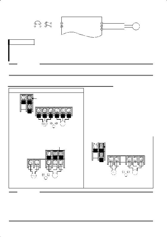
 FR-S520S-0.2K to 1.5K-EC (R)
|
NFB MC |
|
Motor |
||||||||||||||||
Power supply |
|
|
|
|
|
|
|
|
L1 |
U |
|||||||||
|
|
|
|
|
|
|
|
N |
V |
|
|
IM |
|||||||
|
|
|
|
|
|
|
|
|
|
|
|||||||||
|
|
|
|
|
|
|
|
|
|
W |
|
|
|
|
|
|
|
|
Earth |
|
|
|
|
|
|
|
|
|
|
|
|
|
|
|
|
|
|
||
|
|
|
|
|
|
|
|
|
|
|
|
|
|
|
|
|
|
|
|
|
|
|
|
|
|
|
|
|
|
|
|
|
|
|
|
|
|
|
|
|
|
|
|
|
|
|
|
|
|
|
|
|
|
|
|
|
|
|
(Ground) |
REMARKS
•To ensure safety, connect the power input to the inverter via a magnetic contactor and earth leakage circuit breaker or no-fuse breaker, and use the magnetic contactor to switch power on-off.
•The output is three-phase 200V.
NOTE
•To prevent a malfunction due to noise, keep the signal cables more than 10cm (3.94inches) away from the power cables.
1.3.2 Layout and wiring of main circuit terminals
FR-S540-0.4K, 0.75K, 1.5K, 2.2K, 3.7K-EC (R)
Jumper
- |
+ |
|
P1 |
L1 L2 L3 U V W
|
|
|
IM |
|
|
|
|
|
|
|
|
|
|
|
|
|
Power |
|
|
Motor |
|
|
|
|
|
|
|
|
|
|
|
|
|
|
|
|
|
|
|
|
|
|
|
|
|
|
|
|
||
supply |
|
|
|
|
|
|
|
|
|
|
|
|
|
|
|
|
|
|
|
|
|
|
|
|
|
|
|
|
|
|
|||
FR-S520S-0.2K, 0.4K, 0.75K-EC (R) |
FR-S520S-1.5K-EC (R) |
|||||||||||||||
|
|
Jumper |
|
|
|
|
|
|
|
|
|
|
|
|
Jumper |
|
|
|
|
|
|
|
|
|
|
|
|
|
|
|
|||
|
|
|
|
|
|
|
|
|
|
|
|
|
|
|||
|
|
|
|
|
|
|
|
|
|
|
|
|
|
|||
|
|
|
|
|
|
|
|
|
|
|
|
|
|
|
|
|
|
|
|
|
|
|
|
|
|
|
|
|
|
|
|
|
|
|
|
- |
+ |
- |
P1 |
+ |
P1 |
|
|
|
|
|
|
|
|
|
|
|
|
|
|
|
|
|
|
|
|
|
|
|
|
|
|
|
|
|
|
|
|
|
|
|
L1 |
|
N |
|
|
|
U |
|
V |
|
W |
|
|
L1 |
|
|
|
N |
|
|
|
|
|
|
|
U |
|
|
|
V |
|
|
|
W |
|
|
|
|
|
|
|
|
|
|
|
|
|
|
||||||||
|
|
|
|
|
|
|
|
|
|
|
|
|
|
|
|
|
|
|
|
|
|
|
|
|
|
|
|
|
|
|
|
|
|
|
|
|
|
|
|
IM |
|||
|
|
|
|
|
|
|
|
|
|
|
|
|
|
|
|
|
|
|
|
|
|
IM |
|
|
|
|
|
||||||||||||||||
|
|
|
|
|
|
|
|
|
|
|
|
|
|
|
|
|
|
|
|
|
|
|
Power |
|
|
|
Motor |
||||||||||||||||
|
|
|
|
|
|
|
|
|
|
|
|
|
|
|
|
|
|
|
|
|
|
|
|
|
|
||||||||||||||||||
|
Power |
|
|
|
Motor |
|
|
|
|
||||||||||||||||||||||||||||||||||
|
|
|
|
|
supply |
|
|
|
|
|
|
|
|
||||||||||||||||||||||||||||||
|
supply |
|
|
|
|
|
|
|
|
|
|
|
|
|
|
|
|
|
|
|
|
|
|
|
|
||||||||||||||||||
|
|
|
|
|
|
|
|
|
|
|
|
|
|
|
|
|
|
|
|
|
|
|
|
|
|
|
|
|
|||||||||||||||
CAUTION
•Connect the motor to U, V, W.
Turning on the forward rotation switch (signal) at this time rotates the motor counterclockwise when viewed from the load shaft.
•For power input wiring, connect L1 to R/L1 of the terminal block and N to S/L2 of the terminal block.
•Do not connect the power supply to U, V and W.
8

1.4 Description of I/O Terminal Specifications
1.4.1 Main circuit
Symbol |
Terminal Name |
Description |
|
R, S, T * |
AC power input |
Connect to the commercial power supply. |
|
<L1, L2, L3> |
|||
|
|
||
U, V, W |
Inverter output |
Connect a three-phase squirrel-cage motor. |
|
N<-> |
DC voltage |
DC voltage common terminal. Not isolated from the |
|
common |
power supply and inverter output. |
||
|
|||
|
Power factor |
Disconnect the jumper from terminals P<+>-P1 and |
|
P<+>, P1 |
improving DC |
connect the optional power factor improving DC reactor |
|
reactor connection |
(FR-BEL). (The single-phase 100V power input model |
||
|
|||
|
|
cannot be connected.) |
Earth (Ground) For grounding the inverter chassis. Must be earthed.
* R, S <L1, N> terminals for single-phase power input.
CAUTION
< >Terminal names in parentheses are those of the EC version.
1.4.2 Control circuit
Input signals
Symbol
|
|
STF |
input |
|
STR |
|
|
|
Contact |
|
RH |
|
RM |
|
|
|
|
|
|
RL |
SD |
|
|
|
|
|
(*1) |
|
|
PC |
|
|
(*1) |
|
|
10 |
|
|
setting |
|
2 |
|
||
|
|
|
Frequency |
|
4 |
|
|
|
|
|
|
Terminal Name |
Description |
|
|
|
|
Forward rotation |
Turn on the STF signal |
When the STF and STR |
|
|
|
to start forward rotation |
signals are turned on |
|
|
||
start |
|
|
|||
and turn it off to stop. |
simultaneously, the stop |
|
|
||
|
|
|
|||
Reverse rotation |
Turn on the STR signal |
command |
|
|
|
to start reverse rotation |
is given. |
|
|
|
|
start |
Input terminal |
|
|
||
and turn it off to stop. |
|
|
|
||
|
|
function selection |
|
|
|
|
Turn on the RH, RM and RL signals |
|
|
||
|
(Pr. 60 to Pr. 63) |
|
|
||
|
in appropriate combinations to select |
|
|
||
Multi-speed |
changes the |
|
|
||
multiple speeds. |
|
terminal functions. |
|
|
|
selection |
The priorities of the speed commands |
|
|
||
(*4) |
|
|
|||
|
are in order of jog, multi-speed setting |
|
|
|
|
|
(RH, RM, RL, REX) and AU. |
|
|
|
|
Contact input |
Common terminal for contact inputs |
(terminals STF, STR, |
|
|
|
RH, RM, RL) and indicator connection (terminal FM). |
|
|
|||
common (sink) |
|
|
|||
Isolated from terminals 5 and SE. |
|
|
|
||
|
|
|
1 |
||
|
When connecting the transistor output (open collector |
|
|||
External |
output), such as a programmable controller (PLC), |
|
|
||
transistor |
connect the positive external power supply for transistor |
|
|
||
common |
output to this terminal to prevent a malfunction caused by |
|
|
||
24VDC power |
undesirable current. |
|
|
|
|
supply |
This terminal can be used as a 24V 0.1A DC power |
|
|
||
Contact input |
output across terminals PC-SD. |
|
|
|
|
common (source) |
When source logic is selected, this terminal serves as a |
|
|
||
Frequency setting |
contact input signal common. |
|
|
|
|
5VDC. Permissible load current 10mA. |
|
|
|||
power supply |
By entering 0 to 5VDC (0 to 10VDC), the maximum |
|
|
||
|
|
|
|||
Frequency |
output frequency is reached at 5V (10V) and I/O are |
|
|
||
setting |
proportional. Use Pr. 73 "0-5V/0-10V selection" to switch |
|
|
||
(Voltage signal) |
between 5V and 10V. |
|
|
|
|
|
Input resistance 10kΩ . Maximum permissible voltage 20V. |
|
|
||
|
Enter 4-20mADC. This signal is factory-adjusted to reach |
|
|
||
Frequency |
0Hz at 4mA and 60Hz at 20mA. Maximum permissible |
|
|
||
input current 30mA. Input resistance approximately 250Ω . |
|
|
|||
setting |
|
|
|||
For current input, turn on the signal AU. |
|
|
|||
(Current signal) |
|
|
|||
Set the AU signal in any of Pr. 60 to Pr. 63 (input |
|
|
|||
|
|
|
|||
|
terminal function selection). |
|
|
|
|
9

|
Symbol |
Terminal Name |
|
|
Description |
|
|||
signals |
|
|
|
Frequency |
Common terminal for the frequency setting signals |
||||
5 |
|
|
setting input |
(terminals 2, 4) and indicator connection (terminal AM). |
|||||
Input |
|
|
|
common |
Isolated from terminals SD and SE. Do not earth. |
||||
|
|
|
|
|
|
|
|
||
|
|
|
|
|
|
|
|
||
|
|
|
|
|
Change-over contact output indicating |
|
|||
|
A |
|
|
|
that the output has been stopped by the |
|
|||
|
|
|
|
inverter's protective function activated. |
|
||||
|
B |
|
|
Alarm output |
230V 0.3A AC, 30V 0.3A DC. Alarm: |
Output |
|||
|
C |
|
|
|
discontinuity across B-C (continuity |
||||
|
|
|
|
terminal |
|||||
|
|
|
|
|
across A-C), normal: continuity across |
||||
|
|
|
|
|
function |
||||
|
|
|
|
|
B-C (discontinuity across A-C). (*6) |
||||
|
|
|
|
|
selection |
||||
|
Open collector |
|
|
|
Switched low when the inverter output |
(Pr. 64, Pr. 65) |
|||
|
|
|
|
changes the |
|||||
|
|
|
|
frequency is equal to or higher than the |
|||||
|
|
|
|
terminal |
|||||
|
|
|
|
starting frequency (factory set to 0.5Hz, |
|||||
|
RUN |
Inverter running |
functions. (*5) |
||||||
signals |
variable). Switched high during stop or |
||||||||
|
|
|
|
||||||
|
|
|
DC injection brake operation. (*2) |
|
|||||
|
|
|
Permissible load 24VDC 0.1A DC. |
|
|||||
|
|
|
|
|
|
|
|||
Output |
SE |
|
|
Open collector |
Common terminal |
for inverter running |
terminal RUN. |
||
|
|
output common |
Isolated from terminals 5 and SD. |
|
|||||
|
|
|
|
||||||
|
|
|
|
|
|
Factory setting of output item: |
|||
|
|
|
For meter |
One selected from |
|
Frequency |
|
||
|
|
|
|
Permissible load current 1mA |
|||||
|
|
|
|
output frequency |
|
||||
|
|
|
|
|
1440 pulses/s at 60Hz |
||||
|
|
|
|
and motor current is |
|||||
|
|
|
|
|
|
||||
|
|
|
|
output. |
|
|
|
||
Indicator |
AnalogPulse |
AM FM <Japanese><NA, EC> |
|
|
|
|
|||
|
The output signal is |
|
Factory setting of output item: |
||||||
Analog signal |
proportional to the |
|
|||||||
magnitude of each |
|
Frequency |
|
||||||
output |
monitoring item. |
|
Output signal 0 to 5VDC |
||||||
|
|
|
Permissible load current 1mA |
||||||
|
|
|
|
|
|||||
|
|
|
|
|
|
|
|||
Communication |
|
|
|
|
Using the parameter unit connection cable (FR-CB201 to |
||||
−− |
|
|
RS-485 connector |
205), the parameter unit (FR-PU04) is connectable. |
|||||
|
|
(*3) |
Communication operation can be performed through |
||||||
|
|
|
|||||||
|
|
|
|
RS-485. |
|
|
|
||
|
|
|
|
|
|
|
|
||
|
|
|
|
|
|
|
|
|
|
*1. Do not connect terminals SD and PC each other or to the earth.
For sink logic, terminal SD acts as the common terminal of contact input. For source logic, terminal PC acts as the common terminal of contact input. (Refer to page 25 for the way to switch between them.)
*2. Low indicates that the open collector outputting transistor is on (conducts). High indicates that the transistor is off (does not conduct).
*3. Compatible with only the type having RS-485 communication function. (Refer to page 41.)
*4. RL, RM, RH, RT, AU, STOP, MRS, OH, REX, JOG, RES, X14, X16, (STR) signal selection (Refer to page 88.)
*5. RUN, SU, OL, FU, RY, Y12, Y13, FDN, FUP, RL, LF, ABC signal selection (Refer to page 90.)
*6. To be compatible with the European Directive (Low Voltage Directive), the operating capacity of relay outputs (A, B, C) should be 30V 0.3A DC.
10

1.5 How to Use the Main Circuit Terminals
1.5.1 Cables, wiring lengths, crimping terminals, etc.
The following selection example assumes the wiring length of 20m (65.62feet).
1)FR-S520-0.1K to 3.7K (-R) (-C) FR-S520-0.1K to 3.7K-NA
|
|
|
|
|
|
|
|
|
PVC |
||
Applicable |
Terminal |
Tightening |
Crimping |
|
Cables |
|
Insulated |
||||
Inverter |
Screw |
Torque |
Terminals |
|
|
|
|
Cables |
|||
Model |
Size |
N m |
|
|
mm2 |
AWG |
mm2 |
||||
|
|
|
R, S, T |
U, V, W |
R, S, T |
U, V, W |
R, S, T |
U, V, W |
R, S, T |
U, V, W |
|
FR-S520-0.1K |
M3.5 |
1.2 |
2-3.5 |
2-3.5 |
2 |
2 |
14 |
14 |
2.5 |
2.5 |
|
to 0.75K |
|||||||||||
|
|
|
|
|
|
|
|
|
|
||
FR-S520- |
M4 |
1.5 |
2-4 |
2-4 |
2 |
2 |
14 |
14 |
2.5 |
2.5 |
|
1.5K, 2.2K |
|||||||||||
|
|
|
|
|
|
|
|
|
|
||
FR-S520-3.7K |
M4 |
1.5 |
5.5-4 |
5.5-4 |
3.5 |
3.5 |
12 |
12 |
4 |
2.5 |
|
2)FR-S540-0.4K to 3.7K (-R) FR-S540-0.4K to 3.7K-NA (R) FR-S540-0.4K to 3.7K-EC (R)
|
|
|
|
|
|
|
|
|
|
PVC |
|
|
|
|
Crimping |
|
|
Cables |
|
Insulated |
|||
Applicable |
Terminal |
Tightening |
Terminals |
|
|
|
|
|
Cables |
||
Inverter |
Screw |
Torque |
|
|
mm2 |
|
AWG |
mm2 |
|||
Model |
Size |
N m |
R, S, T |
|
R, S, T |
|
|
R, S, T |
|
R, S, T |
|
|
|
|
<L1, L2, |
U, V, W |
<L1, L2, |
U, V, W |
<L1, L2, |
U, V, W |
<L1, L2, |
U, V, W |
|
|
|
|
L3> |
|
L3> |
|
|
L3> |
|
L3> |
|
FR-S540-0.4K |
M4 |
1.5 |
2-4 |
2-4 |
2 |
|
2 |
14 |
14 |
2.5 |
2.5 |
to 3.7K |
|
||||||||||
|
|
|
|
|
|
|
|
|
|
|
|
3)FR-S520S-0.1K to 1.5K (-R) FR-S520S-0.2K to 1.5K-EC (R)
|
|
|
|
|
|
|
|
|
PVC |
|
|
|
Applicable |
Terminal |
Tightening |
Crimping |
|
Cables |
|
Insulated |
|
|
|||
Terminals |
|
|
|
|
Cables |
|
|
|||||
|
|
|
|
|
||||||||
Inverter |
Screw |
Torque |
|
|
mm2 |
AWG |
mm2 |
|
1 |
|||
Model |
Size |
N m |
|
|
|
|||||||
R, S |
U, V, W |
R, S |
U, V, W |
R, S |
U, V, W |
R, S |
U, V, W |
|
||||
|
|
|
|
|
||||||||
|
|
|
<L1, N> |
|
<L1, N> |
|
<L1, N> |
|
<L1, N> |
|
|
|
FR-S520S- |
M3.5 |
1.2 |
2-3.5 |
2-3.5 |
2 |
2 |
14 |
14 |
2.5 |
2.5 |
|
|
0.1K to 0.75K |
|
|
||||||||||
|
|
|
|
|
|
|
|
|
|
|
|
|
FR-S520S- |
M4 |
1.5 |
2-4 |
2-4 |
2 |
2 |
14 |
14 |
2.5 |
2.5 |
|
|
1.5K |
|
|
||||||||||
|
|
|
|
|
|
|
|
|
|
|
|
|
4)FR-S510W-0.1K to 0.75K (-R) FR-S510W-0.1K to 0.75K-NA
|
|
|
|
|
|
|
|
|
|
PVC |
|
Applicable |
Terminal |
Tightening |
Crimping |
|
|
Cables |
|
Insulated |
|||
Terminals |
|
|
|
|
|
Cables |
|||||
Inverter |
Screw |
Torque |
|
|
|
|
|
|
|
|
|
|
|
mm2 |
|
AWG |
mm2 |
||||||
Model |
Size |
N m |
|
|
|
||||||
|
|
|
R, S |
U, V, W |
R, S |
U, V, W |
R, S |
U, V, W |
R, S |
U, V, W |
|
|
|
|
|
|
|
|
|
|
|
<L1, N> |
|
FR-S510W- |
M3.5 |
1.2 |
2-3.5 |
2-3.5 |
2 |
|
2 |
14 |
14 |
2.5 |
2.5 |
0.1K to 0.4K |
|
||||||||||
|
|
|
|
|
|
|
|
|
|
|
|
FR-S510W- |
M4 |
1.5 |
5.5-4 |
2-4 |
3.5 |
|
2 |
12 |
14 |
4 |
2.5 |
0.75K |
|
||||||||||
|
|
|
|
|
|
|
|
|
|
|
|
11
 Wiring length
100m (328.08feet) maximum. (50m (164.04feet) maximum for the FR-S540-0.4K.)
CAUTION
•When the wiring length of the 0.1K or 0.2K is 30m (98.43feet) or more, use the carrier frequency to 1kHz.
•Use the carrier frequency of 1kHz when the wiring length of the FR-S540-0.4K, 0.75K is 30m (98.43feet) or more.
•The wiring length should be 30m (98.43feet) maximum when automatic torque boost is selected in Pr. 98 "automatic torque boost selection (motor capacity)". (Refer to page 109)
1.5.2 Wiring instructions
1)Use insulation-sleeved crimping terminals for the power supply and motor cables.
2)Application of power to the output terminals (U, V, W) of the inverter will damage the inverter. Never perform such wiring.
3)After wiring, wire off-cuts must not be left in the inverter.
Wire off-cuts can cause an alarm, failure or malfunction. Always keep the inverter clean.
When drilling a control box etc., take care not to let wire off-cuts enter the inverter.
4)Use cables of the recommended size to make a voltage drop 2% maximum.
If the wiring distance is long between the inverter and motor, a main circuit cable voltage drop will cause the motor torque to decrease especially at the output of a low frequency.
5)For long distance wiring, the fast-response current limit function may be reduced or the devices connected to the secondary side may malfunction or become faulty under the influence of a charging current due to the stray capacity of wiring. Therefore, note the maximum overall wiring length.
6)Electromagnetic wave interference
The input/output (main circuit) of the inverter includes harmonic components, which may interfere with the communication devices (such as AM radios) used near the inverter. In this case, install the optional FR-BIF radio noise filter (for use in the input side only) or FR-BSF01 or FR-BLF line noise filter to minimize interference.
7)Do not install a power capacitor, surge suppressor or radio noise filter (FR-BIF option) in the output side of the inverter.
This will cause the inverter to trip or the capacitor and surge suppressor to be damaged. If any of the above devices are connected, remove them. (When using the FR-BIF radio noise filter with a single-phase power supply, connect it to the input side of the inverter after isolating the T <L3> phase securely.)
8)Before starting rewiring or other work after performing operation once, check the voltage with a meter etc. more than 10 minutes after power-off. For some time after power-off, there is a dangerous voltage in the capacitor.
12

1.5.3 Peripheral devices
(1) Selection of peripheral devices
Check the capacity of the motor applicable to the inverter you purchased. Appropriate peripheral devices must be selected according to the capacity.
Refer to the following list and prepare appropriate peripheral devices:
1)FR-S520-0.1K to 3.7K (-R) (-C) FR-S520-0.1K to 3.7K-NA
Motor |
|
Rated current of |
Magnetic |
Power |
Power |
Cables (mm2) |
||
|
Factor |
Factor |
(*2) |
|||||
Inverter |
Circuit Breaker |
Contactor |
||||||
Output |
Improving |
Improving |
|
|
||||
(kW |
Model |
(Refer to |
(MC) |
AC Reactor |
DC Reactor |
|
|
|
page 15) |
(Refer to |
R, S, T |
U, V, W |
|||||
(HP)) |
|
(*1) |
page 17) |
(Refer to |
(Refer to |
|
|
|
|
|
page 18) |
page 18) |
|
|
|||
|
|
|
|
|
|
|||
0.1 |
FR-S520- |
30AF/5A |
S-N10 |
FR-BAL-0.4K |
FR-BEL-0.4K |
2 |
2 |
|
(1/8) |
0.1K |
(*3) |
(*3) |
|||||
|
|
|
|
|||||
0.2 |
FR-S520- |
30AF/5A |
S-N10 |
FR-BAL-0.4K |
FR-BEL-0.4K |
2 |
2 |
|
(1/4) |
0.2K |
(*3) |
(*3) |
|||||
|
|
|
|
|||||
0.4 |
FR-S520- |
30AF/5A |
S-N10 |
FR-BAL-0.4K |
FR-BEL-0.4K |
2 |
2 |
|
(1/2) |
0.4K |
|||||||
|
|
|
|
|
|
|||
0.75 |
FR-S520- |
30AF/10A |
S-N10 |
FR-BAL- |
FR-BEL- |
2 |
2 |
|
(1) |
0.75K |
0.75K |
0.75K |
|||||
|
|
|
|
|||||
1.5 |
FR-S520- |
30AF/15A |
S-N10 |
FR-BAL-1.5K |
FR-BEL-1.5K |
2 |
2 |
|
(2) |
1.5K |
|||||||
|
|
|
|
|
|
|||
2.2 |
FR-S520- |
30AF/20A |
S-N11, |
FR-BAL-2.2K |
FR-BEL-2.2K |
2 |
2 |
|
(3) |
2.2K |
S-N12 |
||||||
|
|
|
|
|
||||
3.7 |
FR-S520- |
30AF/30A |
S-N20 |
FR-BAL-3.7K |
FR-BAL-3.7K |
3.5 |
3.5 |
|
(5) |
3.7K |
|||||||
|
|
|
|
|
|
|||
2)FR-S540-0.4K to 3.7K (-R) FR-S540-0.4K to 3.7K-NA (R) FR-S540-0.4K to 3.7K-EC (R)
|
|
Rated current of |
Magnetic |
Power |
Power |
Cables (mm2) |
1 |
|
Motor |
|
Factor |
Factor |
(*2) |
||||
|
Circuit Breaker |
Contactor |
|
|||||
Output |
Inverter |
Improving |
Improving |
|
|
|
||
(kW |
Model |
(Refer to |
(MC) |
AC Reactor |
DC Reactor |
R, S, T |
U, V, W |
|
(HP)) |
|
page 15) |
(Refer to |
(Refer to |
(Refer to |
<L1, L2, |
|
|
|
(*1) |
page 17) |
L3> |
|
|
|||
|
|
page 18) |
page 18) |
|
|
|||
|
|
|
|
|
|
|
||
0.4 |
FR-S540- |
30AF/5A |
S-N10 |
FR-BAL- |
FR-BEL- |
2 |
2 |
|
(1/2) |
0.4K |
H0.4K |
H0.4K |
|
||||
|
|
|
|
|
||||
0.75 |
FR-S540- |
30AF/5A |
S-N10 |
FR-BAL- |
FR-BEL- |
2 |
2 |
|
(1) |
0.75K |
H0.75K |
H0.75K |
|
||||
|
|
|
|
|
||||
1.5 |
FR-S540- |
30AF/10A |
S-N10 |
FR-BAL- |
FR-BEL- |
2 |
2 |
|
(2) |
1.5K |
H1.5K |
H1.5K |
|
||||
|
|
|
|
|
||||
2.2 |
FR-S540- |
30AF/15A |
S-N20 |
FR-BAL- |
FR-BEL- |
2 |
2 |
|
(3) |
2.2K |
H2.2K |
H2.2K |
|
||||
|
|
|
|
|
||||
3.7 |
FR-S540- |
30AF/20A |
S-N20 |
FR-BAL- |
FR-BAL- |
2 |
2 |
|
(5) |
3.7K |
H3.7K |
H3.7K |
|
||||
|
|
|
|
|
||||
13

3)FR-S520S-0.1K to 1.5K (-R) FR-S520S-0.2K to 1.5K-EC (R)
|
|
|
|
Power |
Power |
Cables (mm2) |
||
Motor |
|
Rated current of |
Magnetic |
Factor |
Factor |
(*2) |
||
|
Circuit Breaker |
Contactor |
Improving |
Improving |
|
|
||
Output |
Inverter |
|
|
|||||
(Refer to |
(MC) |
AC Reactor |
DC Reactor |
|
|
|||
(kW |
Model |
R, S |
|
|||||
page 15) |
(Refer to |
(Refer to |
(Refer to |
U, V, W |
||||
(HP)) |
|
<L1, N> |
||||||
|
|
(*1) |
page 17) |
page 18) |
page 18) |
|
|
|
|
|
|
|
(*3) |
(*3) |
|
|
|
0.1 |
FR-S520S- |
30AF/5A |
S-N10 |
FR-BAL-0.4K |
FR-BEL-0.4K |
2 |
2 |
|
(1/8) |
0.1K |
|||||||
|
|
|
|
|
|
|||
0.2 |
FR-S520S- |
30AF/10A |
S-N10 |
FR-BAL-0.4K |
FR-BEL-0.4K |
2 |
2 |
|
(1/4) |
0.2K |
|||||||
|
|
|
|
|
|
|||
0.4 |
FR-S520S- |
30AF/10A |
S-N20 |
FR-BAL- |
FR-BEL- |
2 |
2 |
|
(1/2) |
0.4K |
0.75K |
0.75K |
|||||
|
|
|
|
|||||
0.75 |
FR-S520S- |
30AF/15A |
S-N20 |
FR-BAL-1.5K |
FR-BEL-1.5K |
2 |
2 |
|
(1) |
0.75K |
|||||||
|
|
|
|
|
|
|||
1.5 |
FR-S520S- |
30AF/20A |
S-N21 |
FR-BAL-2.2K |
FR-BEL-2.2K |
2 |
2 |
|
(2) |
1.5K |
|||||||
|
|
|
|
|
|
|||
4)FR-S510W-0.1K to 0.75K (-R) FR-S510W-0.1K to 0.75K-NA
|
|
|
|
Power |
Power |
Cables (mm2) |
||
Motor |
|
Rated current of |
Magnetic |
Factor |
Factor |
(*2) |
||
|
Circuit Breaker |
Contactor |
Improving |
Improving |
|
|
||
Output |
Inverter |
|
|
|||||
(Refer to |
(MC) |
AC Reactor DC Reactor |
|
|
||||
(kW |
Model |
R, S |
|
|||||
page 15) |
(Refer to |
(Refer to |
(Refer to |
U, V, W |
||||
(HP)) |
|
<L1, N> |
||||||
|
|
(*1) |
page 17) |
page 18) |
page 18) |
|
|
|
|
|
|
|
(*3) |
(*4) |
|
|
|
0.1 |
FR-S510W- |
30AF/10A |
S-N10 |
FR-BAL- |
−− |
2 |
2 |
|
(1/8) |
0.1K |
0.75K |
||||||
|
|
|
|
|
||||
0.2 |
FR-S510W- |
30AF/15A |
S-N10 |
FR-BAL-1.5K |
−− |
2 |
2 |
|
(1/4) |
0.2K |
|||||||
|
|
|
|
|
|
|||
0.4 |
FR-S510W- |
30AF/20A |
S-N20 |
FR-BAL-2.2K |
−− |
2 |
2 |
|
(1/2) |
0.4K |
|||||||
|
|
|
|
|
|
|||
0.75 |
FR-S510W- |
30AF/30A |
S-N20 |
FR-BAL-3.7K |
−− |
3.5 |
2 |
|
(1) |
0.75K |
|||||||
|
|
|
|
|
|
|||
*1 For installations in the United States or Canada, the circuit breaker must be inverse time or instantaneous trip type.
*2 The size of the cables assume that the wiring length is 20m (65.62feet). *3 The power factor may be slightly less.
*4 The single-phase 100V power input model does not allow the power factor improving DC reactor to be fitted.
14
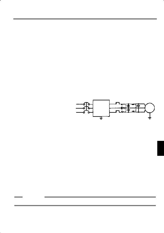
1.5.4 Leakage current and installation of earth leakage circuit breaker
Due to static capacitances existing in the inverter I/O wiring and motor, leakage currents flow through them. Since their values depend on the static capacitances, carrier frequency, etc., take the following counter measures.
(1) To-ground leakage currents
Leakage currents may flow not only into the inverter's own line but also into the other line through the ground cable, etc.
These leakage currents may operate earth leakage circuit breakers and earth leakage relays unnecessarily.
 Counter measures
 If the carrier frequency setting is high, decrease the carrier frequency (Pr. 72) of the inverter.
Note that motor noise increases. Selection of Soft-PWM control (Pr. 70) will make it unoffending. (Factory setting)
 By using earth leakage circuit breakers designed for harmonic and surge suppression (e.g. Mitsubishi's Progressive Super Series) in the inverter's own line and other line, operation can be performed with the carrier frequency kept high (with low noise).
(2) Line-to-line leakage currents
Harmonics of leakage |
NFB |
Thermal relay |
Motor |
|
currents flowing in static |
Power |
Inverter |
IM |
|
capacities between the |
||||
supply |
inverter output cables |
Line static |
|
may operate the external |
||
capacitances |
||
thermal relay |
||
Line-to-Line Leakage Current Path |
||
unnecessarily. |
||
|
 Counter measures
 Use the electronic overcurrent protection of the inverter.
 Decrease the carrier frequency. Note that motor noise increases. Selection of Soft-PWM (Pr. 70) makes it unoffending.
To ensure that the motor is protected against line-to-line leakage currents, it is 1 recommended to use a temperature sensor to directly detect motor temperature.
 Installation and selection of no-fuse breaker
On the power receiving side, install a no-fuse breaker (NFB) to protect the primary wiring of the inverter. Which NFB to choose depends on the power supply side power factor (which changes with the power supply voltage, output frequency and load) of the inverter. Especially as the completely electromagnetic type NFB changes in operational characteristic with harmonic currents, you need to choose the one of a little larger capacity. (Check the data of the corresponding breaker.) For the earth leakage circuit breaker, use our product designed for harmonic and surge suppression (Progressive Super Series). (Refer to page 13 for the recommended models.)
CAUTION
Choose the NFB type according to the power supply capacity.
15
(3) Selecting the rated sensitivity current for the earth leakage circuit breaker
When using the earth leakage circuit breaker with the inverter circuit, select its rated sensitivity current as follows, independently of the PWM carrier frequency:
Progressive Super Series |
Example of leakage |
Leakage current |
(Type SP, CF, SF, CP) |
current per 1km in cable |
example of 3-phase |
Rated sensitivity current: |
path during commercial |
induction motor |
I∆ n ≥ 10 × (lg1+Ign+lg2+lgm) |
power supply operation |
during commercial |
Conventional NV series (Type CA, |
when the CV cable is |
power supply |
CS, SS produced prior to '91) |
routed in metal conduit |
operation |
Rated sensitivity current: |
(200V 60Hz) |
(200V 60Hz) |
I∆ n ≥ |
10 × {lg1+lgn+3 × (lg2+lgm)} |
(mA) |
120 |
|
|
|
|
|
|
|
|
|
|
|
|
|
|
|
|
|
|
|
|
|
|
|
(mA) |
2.0 |
|
|
|
|
|
|
|
|
|
|
|
|
|
|
|
|
|
|
|
|
|
||||||||||||||||||
lg1, lg2 : Leakage currents of cable |
100 |
|
|
|
|
|
|
|
|
|
|
|
|
|
|
|
|
|
|
|
|
|
|
|
1.0 |
|
|
|
|
|
|
|
|
|
|
|
|
|
|
|
|
|
|
|
|
|
|||||||||||||||||||||
|
|
|
|
|
|
|
|
|
|
|
|
|
|
|
|
|
|
|
|
|
|
|
|||||||||||||||||||||||||||||||||||||||||||||
|
path during commercial |
|
|
|
|
|
|
|
80 |
|
|
|
|
|
|
|
|
|
|
|
|
|
|
|
|
|
|
|
|
|
|
|
0.7 |
|
|
|
|
|
|
|
|
|
|
|
|
|
|
|
|
|
|
|
|
|
|||||||||||||
|
|
|
|
|
|
|
|
|
|
|
|
|
|
|
|
|
|
|
|
|
|
|
|
|
|
|
|
|
|
|
|
|
|
|
|
|
|
|
|
|
|
|
|
|
|
|
|
|
|
|
|
||||||||||||||||
|
|
|
|
|
|
|
|
current |
|
|
|
|
|
|
|
|
|
|
|
|
|
|
|
|
|
|
|
|
|
|
|
current |
|
|
|
|
|
|
|
|
|
|
|
|
|
|
|
|
|
|
|
|
|
||||||||||||||
|
|
|
|
|
|
|
|
|
|
|
|
|
|
|
|
|
|
|
|
|
|
|
|
|
|
|
|
|
|
|
|
|
|
|
|
|
|
|
|
|
|
|
|
|
|
|
|
|
|
|
|
||||||||||||||||
|
power supply operation |
|
|
|
|
|
|
|
60 |
|
|
|
|
|
|
|
|
|
|
|
|
|
|
|
|
|
|
|
|
|
|
|
0.5 |
|
|
|
|
|
|
|
|
|
|
|
|
|
|
|
|
|
|
|
|
|
|||||||||||||
|
|
|
|
|
|
|
|
|
|
|
|
|
|
|
|
|
|
|
|
|
|
|
|
|
|
|
|
|
|
|
|
|
|
|
|
|
|
|
|
|
|
|
|
|
|
|
|
|
|
|
|
||||||||||||||||
|
|
|
|
|
|
|
|
|
|
|
|
|
|
|
|
|
|
|
|
|
|
|
|
|
|
|
|
|
|
|
0.3 |
|
|
|
|
|
|
|
|
|
|
|
|
|
|
|
|
|
|
|
|
|
|||||||||||||||
lgn* |
: Leakage current of noise |
40 |
|
|
|
|
|
|
|
|
|
|
|
|
|
|
|
|
|
|
|
|
|
|
|
|
|
|
|
|
|
|
|
|
|
|
|
|
|
|
|
|
|
|
|
|
|||||||||||||||||||||
|
|
|
|
|
|
|
|
|
|
|
|
|
|
|
|
|
|
|
|
|
|
|
0.2 |
|
|
|
|
|
|
|
|
|
|
|
|
|
|
|
|
|
|
|
|
|
|||||||||||||||||||||||
|
|
|
|
|
|
|
|
|
|
|
|
|
|
|
|
|
|
|
|
|
|
|
|
|
|
|
|
|
|
|
|
|
|
|
|
|
|
|
|
|
|
|
|
|
|||||||||||||||||||||||
|
filter on inverter input side |
Leakage |
20 |
|
|
|
|
|
|
|
|
|
|
|
|
|
|
|
|
|
|
|
|
|
|
|
Leakage |
0.1 |
|
|
|
|
|
|
|
|
|
|
|
|
|
|
|
|
|
|
|
|
|
||||||||||||||||||
|
|
|
|
|
|
|
|
|
|
|
|
|
|
|
|
|
|
|
|
|
|
|
|
|
|
|
|
|
|
|
|
|
|
|
|
|
|
|
|
|
|
|
|
|
|
||||||||||||||||||||||
lgm |
: Leakage current of motor |
0 |
|
|
|
|
|
|
|
|
|
|
|
|
|
|
|
|
|
|
|
|
|
|
|
|
|
|
|
|
|
|
|
|
|
|
|
|
|
|
|
|
|
|
|
|
|||||||||||||||||||||
|
|
|
|
|
|
|
|
|
|
|
|
|
|
|
|
|
|
|
|
|
|
|
|
|
|
|
|
|
|
|
|
|
|
|
|
|
|
|
|
|
|
|
|||||||||||||||||||||||||
2 3.5 |
|
|
8 142238 80150 |
|
1.5 3.7 7.5 15223755 |
|
|
|
|||||||||||||||||||||||||||||||||||||||||||||||||||||||||||
|
|
|
|
|
|
|
|||||||||||||||||||||||||||||||||||||||||||||||||||||||||||||
|
during commercial power |
|
5.5 |
30 60100 |
|
2.2 5.5 1118.53045 |
|
|
|
||||||||||||||||||||||||||||||||||||||||||||||||||||||||||
|
supply operation |
|
|
|
|
|
|
|
|
|
|
|
|
|
|
|
|
|
|
|
|
|
|
|
|
|
|
|
|
|
|
|
|
2 |
|
|
|
|
|
|
|
|
|
|
|
|
|
|
|
|
|
|
|
|
|
|
|
||||||||||
|
|
|
|
|
|
|
|
|
|
|
|
|
Cable size (mm ) |
Motor capacity (kW) |
|||||||||||||||||||||||||||||||||||||||||||||||||||||
|
|
|
|
|
|
|
|
|
|
|
|
|
|
|
|
|
|||||||||||||||||||||||||||||||||||||||||||||||||||
<Example> |
|
|
|
|
|
|
|
|
|
|
|
|
|
|
|
|
|
|
|
|
|
|
|
|
|
|
|
|
|
|
|
|
|
|
|
|
|
|
|
|
|
|
|
|
|
|
|
|
|
|
|
|
|
|
|
|
|
|
|
|
|
|
|||||
|
|
|
|
|
2mm2 ×5m 2mm2 ×70m |
|
|
|
|
|
|
|
|
|
|
|
|
|
|
|
|
|
|
|
|
|
|
|
|
|
|
|
|
|
|
||||||||||||||||||||||||||||||||
|
|
|
|
|
(16.40feet) |
|
|
(229.66feet) |
|
|
|
|
|
|
|
|
|
|
|
|
|
|
|
|
|
|
|
|
|
|
|
|
|
|
|
|
|
|
|||||||||||||||||||||||||||||
|
|
|
|
|
|
|
|
|
|
|
|
|
|
|
|
|
|
|
|
|
|
|
|
|
|
|
|
|
|
|
|
|
|
|
|
|
|
|
|
|
|
|
|
|
|
|
|
|
|
|
|
|
|
|
|
|
|
|
|
|
|
|
|
|
|
|
|
|
|
|
NV |
|
|
|
Noise |
|
|
|
|
|
|
|
|
|
|
|
|
|
|
|
|
|
|
|
|
|
|
|
|
|
|
|
|
|
|
|
|
|
|
|
|
|
|
|
|
|
|
|
|
|
|
|
|
|
|
||||||||||
|
|
|
|
|
|
|
|
filter |
|
|
|
|
|
|
|
|
|
|
|
|
|
|
|
|
|
|
|
|
3 |
|
|
|
|
|
|
|
|
|
|
|
|
|
|
|
|
|
|
|
|
|
|
|
|
|
|
|
|||||||||||
|
|
|
|
|
|
|
|
|
|
|
|
|
|
|
|
|
|
|
|
|
|
|
|
|
|
|
|
|
|
|
|
|
|
|
|
|
|
|
|
|
|
|
|
|
|
|
|
|
|
|
|
|
|
|
|||||||||||||
|
|
|
|
|
|
|
|
|
|
|
|
|
|
|
Inver- |
|
|
|
|
|
|
|
|
|
|
|
|
|
|
|
|
|
|
|
|
|
|
|
|
|
|
|
|
|
|
|
|
|
|
|
|
|
|
|
|
|
|
|
|
||||||||
|
|
|
|
|
|
|
|
|
|
|
|
|
|
|
|
|
|
|
|
|
|
|
|
|
|
|
IM |
|
200V |
|
|
|
|
|
|
|
|
|
|
|
|
|
|
|
|
|
|
|
|
|
|
|
|||||||||||||||
|
|
|
|
|
|
|
|
|
|
|
|
|
|
|
|
|
|
|
|
|
|
|
|
|
|
|
|
|
|
|
|
|
|
|
|
|
|
|
|
|
|
|
|
|
|
|
|
|
|
||||||||||||||||||
|
|
|
|
|
|
|
|
|
|
|
|
|
|
|
|
|
|
|
|
|
|
|
|
|
|
|
|
|
|
|
|
|
|
|
|
|
|
|
|
|
|
|
|
|
|
|
|
|
|
||||||||||||||||||
|
|
|
|
|
|
|
|
|
|
|
|
|
|
|
ter |
|
|
|
|
|
|
|
|
|
|
|
|
|
|
|
|
|
|
|
|
|
1.5kW |
|
|
|
|
|
|
|
|
|
|
|
|
|
|
|
|
|
|
|
|
|
|
|
|||||||
|
|
|
|
|
|
|
|
|
|
|
|
|
|
|
|
|
|
|
|
|
|
|
|
|
|
|
|
|
|
|
|
|
|
|
|
|
|
|
|
|
|
|
|
|
|
|
|
|
|
|
|
|
|
|
|
|
|
|
|||||||||
|
|
|
|
|
|
|
|
|
|
|
|
|
|
|
|
|
|
|
|
|
|
|
|
|
|
|
|
|
|
|
|
|
|
|
|
|
|
|
(2HP) |
|
|
|
|
|
|
|
|
|
|
|
|
|
|
|
|
|
|
|
|
|
|
|
|||||
|
|
|
|
|
|
|
|
|
|
|
|
|
|
|
|
|
|
|
|
|
|
|
|
|
|
|
|
|
|
|
|
|
|
|
|
|
|
|
|
|
|
|
|
|
|
|
|
|
|
|
|
|
|
|
|
|
|
|
|
|
|
||||||
|
|
|
|
|
|
|
|
|
|
|
|
|
|
|
|
|
|
|
|
|
|
|
|
|
|
|
|
|
|
|
|
|
|
|
|
|
|
|
|
|
|
|
|
|
|
|
|
|
|
|
|
|
|
|
|
|
|
|
|
|
|
||||||
|
|
|
|
|
Ig1 Ign |
Ig2 |
Igm |
|
|
CAUTION |
|
|
|
||
|
|
|
|
|
|||
• |
|
|
|
|
|||
The earth leakage circuit breaker should be installed to the primary (power |
|||||||
• |
supply) side of the inverter. |
|
|
||||
In the |
|
connection neutral point grounded system, the sensitivity current |
|||||
|
|||||||
becomes worse for ground faults in the inverter secondary side. Hence, the protective grounding of the load equipment should be 10Ω or less.
•When the breaker is installed in the secondary side of the inverter, it may be unnecessarily operated by harmonics if the effective value is less than the rating. In this case, do not install the breaker since the eddy current and hysteresis loss increase and the temperature rises.
*Note the leakage current value of the noise filter installed on the inverter input side.
|
Progressive Super Series |
|
Conventional NV |
||
|
(Type SP, CF, SF,CP) |
|
(Type CA, CS, SS) |
||
Leakage current (Ig1) (mA) |
20 × |
5m (16.40feet) |
= 0.10 |
||
1000m (3280.80feet) |
|||||
Leakage current (Ign) (mA) |
|
0 (without noise filter) |
|
||
Leakage current (Ig2) (mA) |
20 × |
70m (229.66feet) |
= 1.40 |
||
1000m (3280.80feet) |
|||||
Motor leakage |
|
0.14 |
|
|
|
current (Igm) (mA) |
|
|
|
||
|
|
|
|
|
|
Total leakage current (mA) |
1.66 |
|
|
|
4.78 |
Rated sensitivity current |
30 |
|
|
|
100 |
(mA) ( ≥ Ig × 10) |
|
|
|
||
|
|
|
|
|
|
16
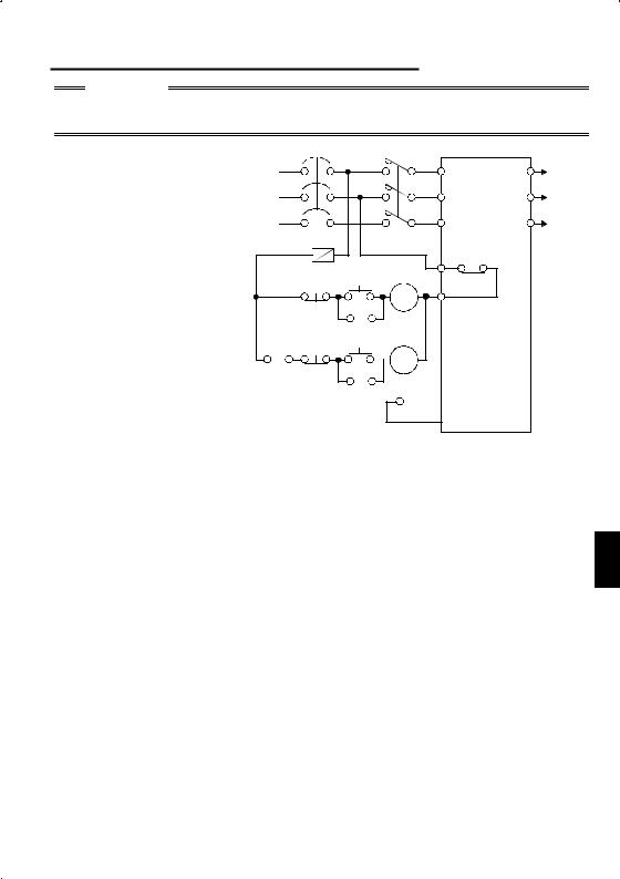
1.5.5 Power-off and magnetic contactor (MC)
CAUTION
Do not use the inverter power supply side magnetic contactor to start or stop the inverter.
As shown on the right, always use the start signal (ON or OFF across terminals STF or STR-SD) to make a start or stop. (Refer to page 28)
NFB
Power supply
F |
OFF |
MC |
OFF |
MC |
|
|
|
R<L1> |
U |
|
|
S<N> |
V |
To |
|
motor |
|||
|
|
||
T |
W |
|
|
|
B |
|
ON |
|
OFF |
|
|
MC |
||
MC |
C |
||
|
ON |
Inverter |
|
 RA
RA
RA
RA

 STF (STR)
 SD
SD
Inverter Start/Stop Circuit Example
(1) Inverter's primary side magnetic contactor (MC)
On the inverter's primary side, it is recommended to provide an MC for the following purposes (Refer to page 13 for selection.):
1)To release the inverter from the power supply when the inverter's protective function is activated or when the drive is not functioning (e.g. emergency stop
operation).
2) To prevent an accident caused by an automatic restart made at power restoration 1 after an inverter stop due to a power failure.
3)To rest the inverter for a long time.
The control power supply for inverter is always running and consumes a little power. When stopping the inverter for a long time, switching inverter power off saves power slightly.
4)To separate the inverter from the power supply to ensure safety of maintenance/inspection work.
As the inverter's primary MC is used for the above purposes, it is equivalent to the standard duty and select the one of class JEM1038-AC3 for the inverter input side current.
17
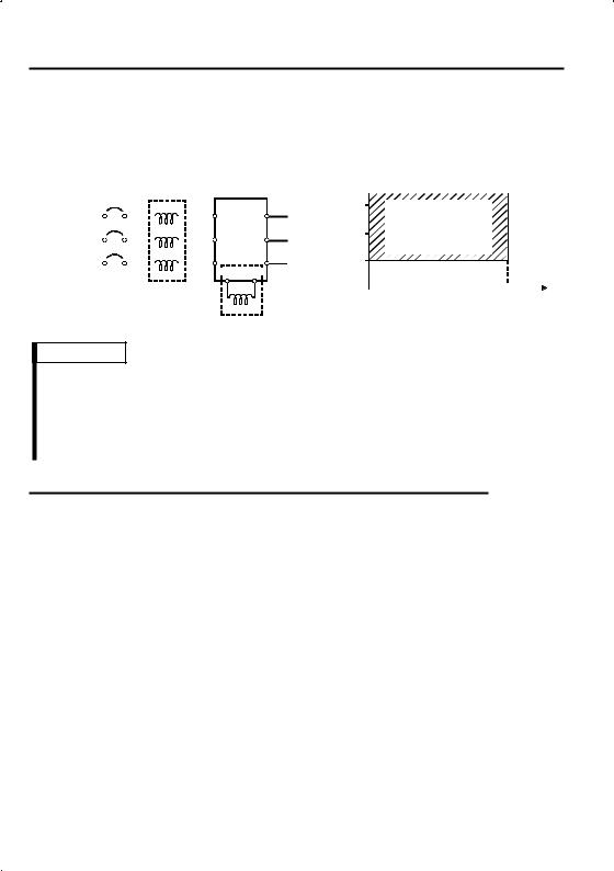
1.5.6 Regarding the installation of the power factor improving reactor
When the inverter is installed near a large-capacity power transformer (500kVA or more at the wiring length of 10m (32.81feet) or less) or the power capacitor is to be switched, an excessive peak current will flow in the power supply input circuit, damaging the converter circuit. In such a case, always install the power factor improving reactor (FR-BEL or FR-BAL).
|
NFB |
FR-BAL |
Inverter |
|||||||
|
R |
|
|
X |
|
|
||||
Power |
|
|
|
|
|
R<L1>U |
||||
|
|
|
|
|
||||||
|
|
|
|
S |
|
Y |
||||
|
|
|
|
|
S<N> V |
|||||
supply |
|
|
|
|
|
|
|
|
||
|
|
|
|
T |
|
|
Z |
T |
W |
|
|
|
|
|
|
|
|||||
 P<+>P1
FR-BEL(*)
Power supply equipment
|
1500 |
Power factor |
|
|
|
||
|
1000 |
improving reactor |
|
(kVA) |
installation range |
||
|
|||
500 |
|
||
|
|
capacity |
|
|
|
|
|
|
0 |
10 |
|||||
|
||||||
Wiring length (m)
REMARKS
*When connecting the FR-BEL, remove the jumper across terminals P<+>-P1. The wiring length between FR-BEL and inverter should be 5m (16.40feet) maximum and as short as possible.
Use the cables which are equal in size to those of the main circuit. (Refer to page 11)
1.5.7 Regarding noise and the installation of a noise filter
Some noise enters the inverter causing it to malfunction and others are generated by the inverter causing the malfunction of peripheral devices. Though the inverter is designed to be insusceptible to noise, it handles low-level signals, so it requires the following general counter measures to be taken.
 General counter measures
 Do not run the power cables (I/O cables) and signal cables of the inverter in parallel with each other and do not bundle them.
 Use twisted shield cables for the detector connecting and control signal cables and connect the sheathes of the shield cables to terminal SD.
 Ground the inverter, motor, etc. at one point.
 Capacitances exist between the inverter's I/O wiring, other cables, earth and motor, through which leakage currents flow to cause the earth leakage circuit breaker, earth leakage relay and external thermal relay to operate unnecessarily. To prevent this, take appropriate measures, e.g. set the carrier frequency in Pr. 72 to a low value, use an earth leakage circuit breaker designed for suppression of harmonics and surges, and use the electronic overcurrent protection built in the inverter.
18
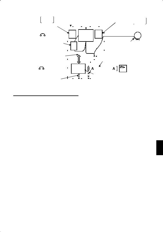
 Noise reduction examples
|
|
|
FR-BLF |
Control |
Reduce carrier |
|
|
|
|
|
|
|
|
FR-BLF |
|||||||||||||||||||||||||
Install filter FR-BSF01 |
|
box |
frequency. |
|
|
|
|
|
|
|
|
|
|
Install filter |
|
||||||||||||||||||||||||
|
|
|
|
|
|
|
|
|
|
|
FR-BSF01 |
||||||||||||||||||||||||||||
on inverter's input side. |
|
|
|
|
|
|
|
|
|
|
|
|
|
|
|
|
|
|
|
|
|
|
|
|
|
|
|
|
on inverter's output side. |
||||||||||
Inverter |
|
|
FR- |
|
|
|
|
|
|
|
|
|
|
|
|
|
FR- |
|
|
|
|
||||||||||||||||||
|
|
|
Inverter |
|
|
|
|
|
|
|
|
|
|
|
|
IM Motor |
|||||||||||||||||||||||
|
|
|
|
|
|
|
|
|
|
|
|
|
|
|
|||||||||||||||||||||||||
|
|
|
|
|
|
|
BLF |
|
|
|
|
|
BLF |
|
|
|
|
|
|
|
|
|
|||||||||||||||||
power supply |
|
|
|
|
|
|
|
|
|
|
|
|
|
||||||||||||||||||||||||||
|
|
|
|
|
|
|
|
|
|
|
|
|
|
|
|
|
|
|
|
|
|
|
|
|
|
|
|
|
|
|
|
|
|
|
|||||
Install filter FR-BIF |
|
|
|
|
|
|
|
|
|
|
|
|
|
|
|
|
|
|
|
|
|
|
|
|
|
|
|
|
|
|
|
|
|
|
|
||||
|
|
|
FR- |
|
|
|
|
|
|
|
|
|
|
|
|
|
|
|
|
|
|
Use 4-core cable for motor |
|||||||||||||||||
on inverter's input side. |
|
|
|
|
|
|
|
|
|
|
|
|
|
|
|
|
|
|
|
|
|
||||||||||||||||||
Separate inverter and power |
|
|
|
BIF |
|
|
|
|
|
|
|
|
|
|
|
|
|
|
|
|
|
|
power cable and use one |
||||||||||||||||
|
|
|
|
|
|
|
|
|
|
|
|
|
|
|
|
|
|
|
|
|
|
|
|
|
cable as earth cable. |
||||||||||||||
line more than 30cm (3.94inches) |
|
|
|
|
|
|
|
|
|
|
|
|
|
|
|
|
|
|
|
|
|
|
|
|
|||||||||||||||
|
|
|
|
|
|
|
|
|
|
|
|
|
|
|
|
|
|
|
|
|
|
|
|
|
|
|
|
|
|
||||||||||
(at least 10cm (11.81inches)) |
|
|
|
|
|
|
|
|
|
|
|
|
|
|
|
|
|
|
|
|
|
|
|
|
|
|
|
|
|
|
|
|
|
|
|
||||
|
|
|
|
|
|
|
|
|
|
|
|
|
|
|
|
|
|
|
|
|
|
Use twisted pair shielded cable. |
|||||||||||||||||
from sensor circuit. |
|
|
|
|
|
|
|
|
|
|
|
|
|
|
|
|
|
|
|
|
|
|
|||||||||||||||||
|
|
|
|
Power |
|
|
|
|
|
|
|
|
|
|
|
|
|
|
|
|
|
|
Sensor |
|
|
|
|
||||||||||||
Control |
|
|
|
|
|
|
|
|
|
|
|
|
|
|
|
|
|
|
|
|
|
|
|
|
|
|
|
|
|
||||||||||
|
|
|
|
|
|
|
|
|
supply |
|
|
|
|
|
|
|
|
|
|
|
|
|
|
|
|
|
|
|
|
|
|
|
|
|
|||||
power supply Do not earth control |
|
|
|
|
|
|
|
|
|
|
|
|
|
|
|
|
|
|
|
|
|||||||||||||||||||
|
|
|
|
for sensor |
|
|
|
|
|
|
|
|
|
|
|
|
|
|
|
|
|
|
|
|
|
|
|
||||||||||||
|
|
|
|
|
|
|
|
|
|
|
|
|
|
|
|
|
|
|
|
|
|
|
|
|
|
||||||||||||||
|
box directly. |
|
|
|
|
|
|
|
|
|
|
|
|
|
|
|
|
|
|
Do not earth shield but connect |
|||||||||||||||||||
|
|
|
|
|
|
|
|
|
|
|
|
|
|
|
|
|
|
|
|||||||||||||||||||||
|
|
|
Do not earth |
|
|
|
|
|
|
|
|
|
|
|
|
|
|
|
|
|
|
it to signal common cable. |
|
|
|
|
|||||||||||||
|
|
|
|
|
|
|
|
|
|
|
|
|
|
|
|
|
|
|
|
|
|
|
|
|
|||||||||||||||
|
|
|
control cable. |
|
|
|
|
|
|
|
|
|
|
|
|
|
|
|
|
|
|
|
|
|
|
|
|
|
|
|
|
|
|
|
|
|
|
|
|
1.5.8 Grounding precautions
 Leakage currents flow in the inverter. To prevent an electric shock, the inverter and motor must be grounded.
 Use the dedicated ground terminal to ground the inverter. (Do not use the screw in the casing, chassis, etc.)
Use a tinned* crimping terminal to connect the earth cable. When tightening the screw, be careful not to break the threads.
*Plating should not include zinc.
 Use the thickest possible ground cable. Use the cable whose size is equal to or
greater than that indicated in the following table, and minimize the cable length. 1 The grounding point should be as near as possible to the inverter.
|
|
(Unit: mm2) |
|
Motor Capacity |
Ground Cable Size |
||
200V, 100V class |
400V class |
||
|
|||
2.2kW (3HP) or less |
2 (2.5) |
2 (2.5) |
|
3.7kW (5HP) |
3.5 (4) |
2 (4) |
|
For use as a product compliant with the Low Voltage Directive, use PVC cable whose size is indicated within parentheses.
 Ground the motor on the inverter side using one cable of the 4-core cable.
19
1.5.9 Regarding power harmonics
The inverter may generate power harmonics from its converter circuit to affect the power generator, power capacitor etc. Power harmonics are different from noise and leakage currents in source, frequency band and transmission path. Take the following counter measure suppression techniques.
 The following table indicates differences between harmonics and noise:
Item |
Harmonics |
Noise |
|
|
Frequency |
Normally 40th to 50th degrees or |
High frequency (several 10kHz |
||
less (up to 3kHz or less) |
to MHz order) |
|
||
|
|
|||
Environment |
To-electric channel, power |
To-space, distance, wiring path |
||
impedance |
||||
|
|
|
||
Quantitative |
Theoretical calculation possible |
Random occurrence, quantitative |
||
understanding |
grasping difficult |
|
||
|
|
|||
Generated amount |
Nearly proportional to load |
Change with current |
variation |
|
ratio (larger as switching speed |
||||
capacity |
||||
|
increases) |
|
||
|
|
|
||
Affected equipment |
Specified in standard per |
Different depending on |
maker's |
|
immunity |
equipment |
equipment specifications |
||
Suppression example |
Provide reactor. |
Increase distance. |
|
|
 Suppression technique Harmonic currents produced on the power supply side by the inverter change with such conditions as whether there are wiring impedances and a power factor improving reactor and the magnitudes of output frequency and output current on the load side.
|
|
|
|
|
|
|
|
|
|
|
|
|
|
Power factor |
||
|
|
|
|
|
|
|
|
|
|
|
|
|
|
|||
NFB |
|
|
|
improving DC reactor |
||||||||||||
|
|
|
||||||||||||||
|
|
|
|
|
|
|
|
|
|
|
Inverter |
|
|
|
Motor |
|
|
|
|
|
|
|
|
|
|
|
|
|
|
|
|||
|
|
|
|
|
|
|
|
|
|
|
|
|
|
|||
|
|
|
|
|
|
|
|
|
|
|
|
|
|
|
IM |
|
|
|
|
|
|
|
|
|
|
|
|
|
|
|
|
|
|
|
|
|
|
|
|
|
|
|
|
|
|
|
|
|||
|
|
|
|
|
|
|
|
|
|
|
|
|
|
|
|
|
|
|
|
Power factor |
|
Do not provide power factor |
|||||||||||
|
improving AC reactor |
|
improving capacitor. |
|||||||||||||
For the output frequency and output current, we understand that they should be calculated in the conditions under the rated load at the maximum operating frequency.
CAUTION
The power factor improving capacitor and surge suppressor on the inverter output side may be overheated or damaged by the harmonic components of the inverter output. Also, since an excessive current flows in the inverter to activate overcurrent protection, do not provide a capacitor and surge suppressor on the inverter output side when the motor is driven by the inverter. To improve the power factor, insert a power factor improving reactor in the inverter's primary side or DC circuit. For full information, refer to page 18.
1.5.10 Japanese power harmonic suppression guideline
Harmonic currents flow from the inverter to a power receiving point via a power transformer. The harmonic suppression guideline was established to protect other consumers from these outgoing harmonics.
1)[Harmonic suppression guideline for household appliances and general-purpose products]
The "harmonic suppression guideline for household appliances and general-purpose products" issued by ex-Ministry of International Trade and Industry (present Ministry of Economy, Trade and Industry) in September, 1994 applies to the FR-S500 series other than the three-phase 400V class. By installing the FR-BEL or FR-BAL power factor improving reactor, this product complies with the "harmonic suppression techniques for transistorized inverters (input current 20A or less)" established by the Japan Electrical Manufacturers' Association.
20
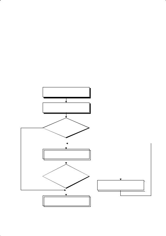
2)"Harmonic suppression guideline for specific consumers"
This guideline sets forth the maximum values of harmonic currents outgoing from a high-voltage or specially high-voltage consumer who will install, add or renew harmonic generating equipment. If any of the maximum values is exceeded, this guideline requires that consumer to take certain suppression measures.
Table 1 Maximum Values of Outgoing Harmonic Currents per 1kW Contract Power
Received Power Voltage |
5th |
7th |
11th |
13th |
17th |
19th |
23rd |
Over |
|
23rd |
|||||||||
|
|
|
|
|
|
|
|
||
6.6kV |
3.5 |
2.5 |
1.6 |
1.3 |
1.0 |
0.9 |
0.76 |
0.70 |
|
22 kV |
1.8 |
1.3 |
0.82 |
0.69 |
0.53 |
0.47 |
0.39 |
0.36 |
|
33 kV |
1.2 |
0.86 |
0.55 |
0.46 |
0.35 |
0.32 |
0.26 |
0.24 |
(1)Application of the harmonic suppression guideline for specific consumers
New installation/addition/ renewal of equipment
Calculation of equivalent capacity sum
Not more than |
|
|
|
|
|
|
|
||
reference capacity |
Sum of equivalent |
|
|
|
|
||||
|
|
|
|
|
|
|
|||
|
|
|
capacities |
|
|
|
|
||
|
|
|
|
|
|
|
|
||
|
Over reference |
|
|
|
|
|
|
||
|
capacity |
|
|
|
|
|
1 |
||
|
|
Calculation of outgoing |
|
|
|
||||
|
|
|
|
|
|||||
|
|
harmonic current |
|
|
|
|
|||
|
|
|
|
|
|
|
|
|
|
|
|
|
|
|
|
|
|
|
|
|
|
|
Is outgoing harmonic |
Over maximum value |
|||||
|
|
|
current equal to or lower |
|
|||||
|
|
|
|
|
|
|
|
||
|
|
|
than maximum value? |
|
|
|
|
||
|
|
|
|
|
|
|
|||
|
|
|
|
Harmonic suppression |
|
|
Not more than |
technique is required. |
|
|
|
|
||
|
|
maximum value |
|
|
|
|
|
|
|
|
Harmonic suppression |
|
|
|
|
|
|
||
|
technique is not required. |
|
|
|
|
|
|
|
|
21
Loading...