


70
Table of contents
 Loading...

SanDisk and SanDisk logos are registered trademarks of SanDisk Corporation, U.S.A.
MELDAS is a registered trademark of Mitsubishi Electric Corporation.
Other company and product names that appear in thi s manual are registered tra dema rks or tradema rks of
their respective companies.
Introduction
This manual is called MITSUBISHI CNC 70 Series CONNECTION MANUAL and covers the
items related to installation, connection and maintenance of this NC unit. Read this manual
thoroughly before using. For safe use, fully understand "Precautions for Safety" on the next
page first.
Details described in this manual:
CAUTION
For items described as "Restrictions" or "Usable State" in this manual, the instruction
manual issued by the machine tool builder takes precedence over this manual.
Items that are not described in this manual must be interpreted as "not possible".
This manual is written on the assumption that all option functions are added. Confirm the
specifications issued by the machine tool builder before use.
Refer to the Instruction Manual issued by each machine tool builder for details on each
machine tool.
Some screens and functions may differ depending on each NC system (or version), and
some functions may not be possible. Please confirm the specifications before use.
The numerical control unit is configured of the control unit, display unit, operation board, servo drive
unit, spindle drive unit, power supply unit + driver, servomotor, and spindle motor, etc.
In this manual, the following items are generically called the "controller".
• Control unit
• Display unit
• Operation board
• Numerical control unit peripheral devices (input/output unit, safety unit)
In this manual, the following items are generically called the "drive unit".
• Servo drive unit
• Spindle drive unit
• Power supply unit + driver
In this manual, the following items are generically called the "motor".
• Servomotor
• Spindle motor
Precautions for Safety
Always read this manual and enclosed documents before installation, operation, maintenance
and inspection to ensure correct usage. Thoroughly understand the basics, safety information
and precautions of the devices before using.
This manual classifies the safety precautions into "DANGER", "WARNING" and "CAUTION".
DANGER
WARNING
CAUTION
Note that the items under " CAUTION" could lead to serious consequences as well
depending on the situation. Please follow all items listed in "Precautions for Safety" as they
are equally important.
When the user could be subject to imminent fatalities or
serious injuries if handling is mistaken.
When the user could be subject to fatalities or serious
injuries if handling is mistaken.
When the user could be subject to minor or moderate
injuries or the property could be damaged if handling is
mistaken.
For Safe Use
This product is not designed or manufactured on the assumption that the product will be
used for the equipment or systems that are to be subject to any fatal consequences.
Please inquire our customer service department about any particular usage other than the
normal usage as a machine tool.
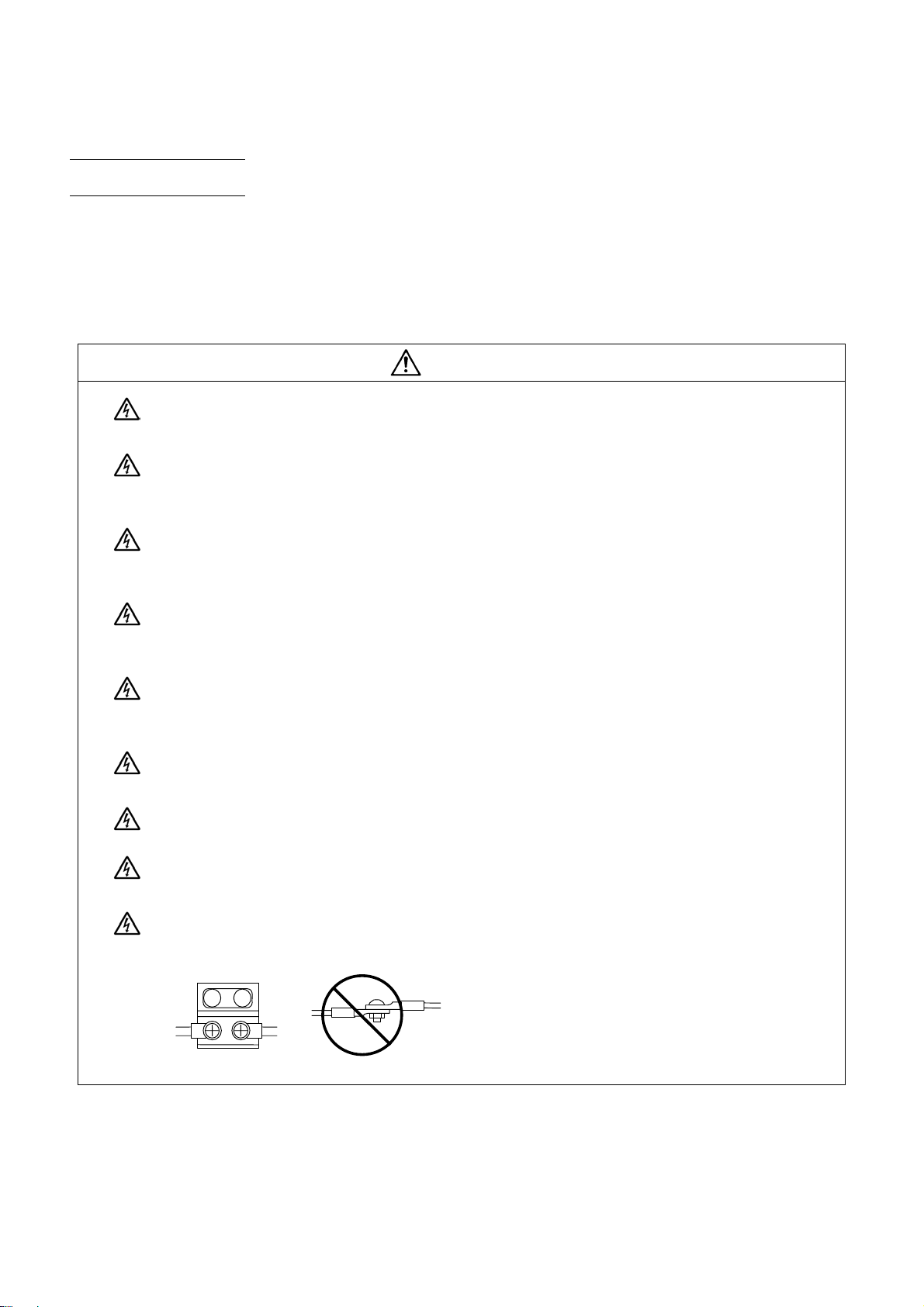
1. Items related to prevention of electric shocks
WARNING
Do not open or remove the front cover while the power is ON or during operation. The high voltage
terminals and charged sections will be exposed, and this could result in electric shocks.
Do not remove the front cover even when the power is OFF, except for the wiring works or periodic
inspections. The inside of the controller and drive unit are charged, and this could result in electric
shocks.
Always wait at least 15 minutes after turning the power OFF. Then, check the voltage with a tester,
etc., before wiring works, inspections or connecting with peripheral devices. Failure to observe this
could result in electric shocks.
Earth ground the controller, drive unit and motor according to the local laws. (In Japan, ground the
200V Series input products with Class C or higher protective grounding and the 400V Series input
with Class D or higher protective grounding.)
All wiring works, maintenance and inspections must be carried out by a qualified technician. Failure
to observe this could result in electric shocks. Contact your nearby Service Center or Service Station
for replacing parts and servicing.
Wire the controller, drive unit and motor after installation. Failure to observe this could result in
electric shocks.
Do not operate the switches with wet hands. Failure to observe this could result in electric shocks.
Do not damage, apply excessive stress, place heavy things on or sandwich the cables. Failure to
observe this could result in electric shocks.
Insulate the power lead using a fixed terminal block. Failure to observe this could result in electric
shocks.
2. Items related to prevention of fire
CAUTION
Install the controller, drive unit, motor and regenerative resistor on non-combustible material.
Installation directly on or near combustible materials could result in fires.
If any malfunction in the unit is observed, shut off the power at the unit’s power supply side.
Continuous flow of large current could result in fires.
Install an appropriate no fuse breaker (NFB) and contactor (MC) on the power input section of the
drive unit and configure the sequence that shuts the power off upon drive unit’s emergency stop or
alarm.
When a breaker is shared for multiple power supply units, the breaker may not function upon
short-circuit failure in a small capacity unit. Do not share a breaker for multiple units as this is
dangerous.
Incorrect wiring and connections could cause the devices to damage or burn.
3. Items related to prevention of bodily injury or property damage
DANGER
When transporting or installing a built-in IPM spindle or linear servomotor, be careful so that your
hand or property will not be trapped in the motors or other metal objects. Also keep the devices with
low magnetic tolerance away from the product.
CAUTION
Do not apply voltages to the connectors or terminals other than voltages indicated in the connection
manual for the controller or specifications manual for the drive unit. Failure to observe this could
cause the devices to rupture or damage, etc.
Incorrect connections could cause the devices to rupture or dam ag e, etc. Always connect the cables
to the indicated connectors or terminals.
Incorrect polarity (+ -) could cause the devices to rupture or damage, etc.
Persons wearing medical devices, such as pacemakers, must stay away from this unit. The
electromagnetic waves could adversely affect the medical devices.
Fins on the rear of the unit, regenerative resistor and motor, etc., will be hot during operation and for
a while after the power has been turned OFF. Do not touch or place the parts and cables, etc. close
to these sections. Failure to observe this could result in burns.
Do not enter the machine’s movable range during automatic operation. Keep your hands, feet or
face away from the spindle during rotation.
4. General precautions
Always follow the precautions below. Incorrect handling could result in faults, injuries or electric shocks, etc.
(1) Transportation and installation
CAUTION
Correctly transport the products according to the mass.
Use motor’s suspension bolts to transport the motor itself. Do not use it to transport the motor after
installation onto the machine.
Do not stack the products exceeding the indicated limit.
Do not hold the cables, shaft or detector when transporting the motor.
Do not transport the controller or drive unit by suspending or holding the connected wires or cables.
Do not hold the front cover when transporting the unit, or the front cover could come off, causing the
unit to drop.
Install on a non-combustible place where the unit’s or motor ’s mass can be withstood according to
the instruction manual.
The motor does not have a complete water-proof (oil-proof) structure. Do not allow oil or water to
contact or enter the motor. Prevent the cutting chips from being accumulated on the motor as they
easily soak up oil.
When installing the motor facing upwards, take measures on the machine side so that gear oil, etc.,
will not enter the motor shaft.
Do not remove the detector from the motor. (The detector installation screw is treated with sealing.)
Do not allow foreign matters, especially, conductive foreign matters such as screws or metal chips,
or combustible foreign matters such as oil, to enter the controller, drive unit or motor. Failure to
observe this could result in rupture or damage.
Do not get on the product or place heavy objects on it.
Provide prescribed distance between the controller/drive unit and inner surface of the control
panel/other devices.
Do not install or operate the controller, drive unit or motor that is damaged or has missing parts.
Take care not to cut hands, etc. with the heat radiating fins or metal edges.
Do not block the intake/outtake ports of the motor with the cooling fan.
Install the controller’s display section and operation board section on the spot where cutting oil will
not reach.
CAUTION
The controller, drive unit an d motor are preci sion devices, so do not drop or apply thumping vib ration
and strong impacts on them.
Hard disk unit is a precision device, so do not drop or apply strong impacts on it.
Store and use the units according to the environment conditions indicated in each specifications
manual.
Securely fix the motor to the machine. The motor could come off during operation if insecurely fixed.
Always install the motor with reduction gear in the designated direction. Failure to observe this coul d
result in oil leaks.
Always install a cover, etc., over the shaft so that the rotary section of the motor cannot be touched
during motor rotation.
When installing a coupling to the servomotor shaft end, do not apply imp acts b y hammering, etc. The
detector could be damaged.
Use a flexible coupling when connecting with a ball screw, etc., and keep the shaft core deviation
smaller than the tolerable radial load of the shaft.
Do not use a rigid coupling as an excessive bending load will be applied on the shaft and could
cause the shaft to break.
(2) Items related to wiring
Do not apply a load exceeding the tolerable level onto the motor shaft. The sh aft or bearing could be
damaged.
Before using this product after a long period of storage, please cont act the Mit subishi Service Station
or Service Center.
Following the UN recommendations, battery units and batteries should be transported based on the
international regulations such as those determined by International Civil Aviation Organization
(ICAO), International Air Transport Association (IATA), International Maritime Organization (IMO)
and U.S. Department of Transportation (DOT).
Correctly wire this product. Failure to observe this could result in motor runaway, etc.
Do not install a phase advancing capacitor, surge absorber or radio noise filter on the output side of
the drive unit.
Correctly connect the output side (terminal U, V, W). The motor will not run properly if incorrectly
connected.
CAUTION
Always install an AC reactor per each power supply unit.
A
CAUTION
Always install an appropriate breaker per each power supply unit. A breaker cannot be shared for
multiple power supply units.
Do not directly connect a commercial power supply to the motor. Failure to observe this could result
in faults.
When using an inductive load such as relays, always connect a diode in parallel to the load as a
noise countermeasure.
When using a capacitive load such as a lamp, always connect a protective resistor in series to the
load to suppress rush currents.
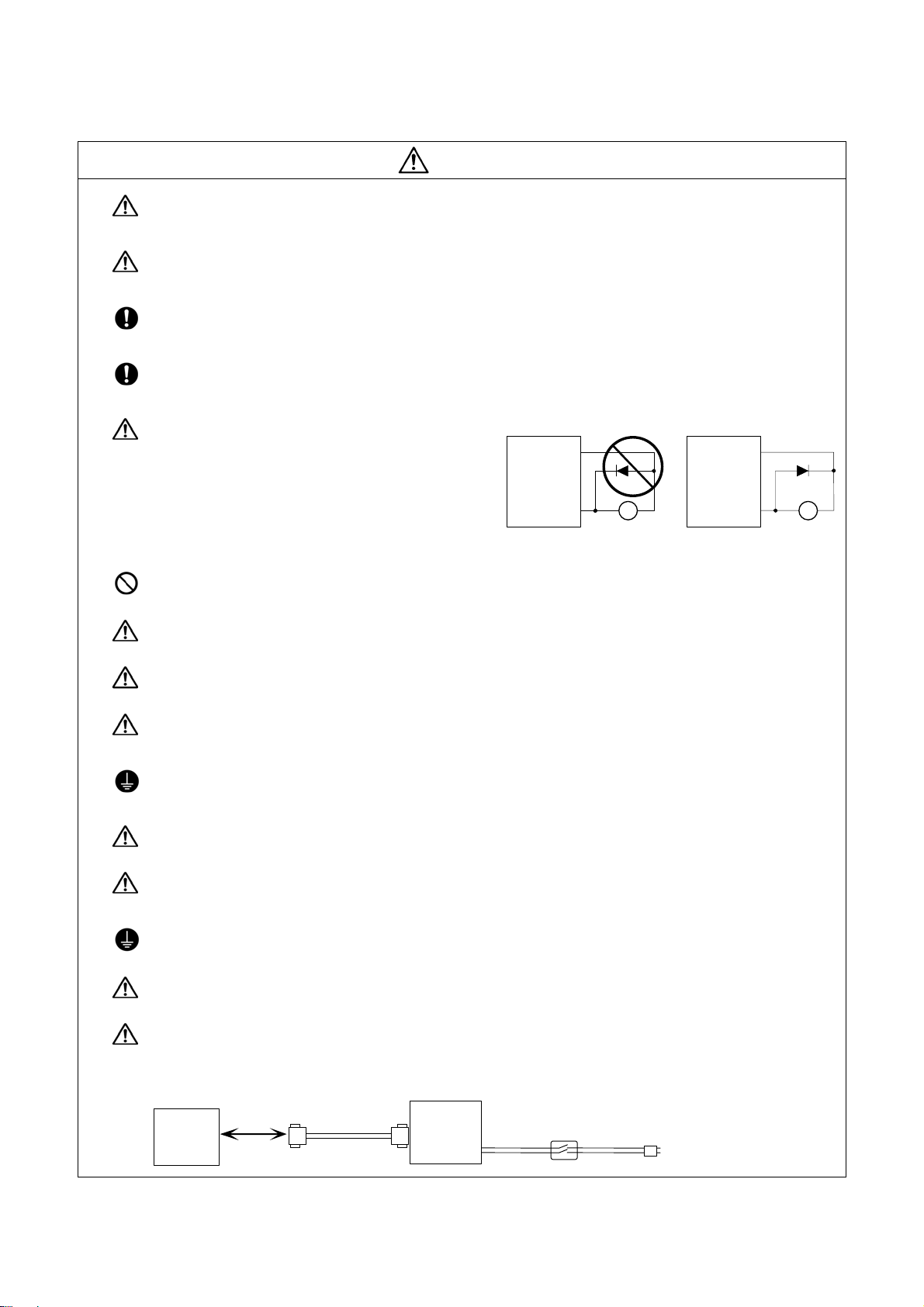
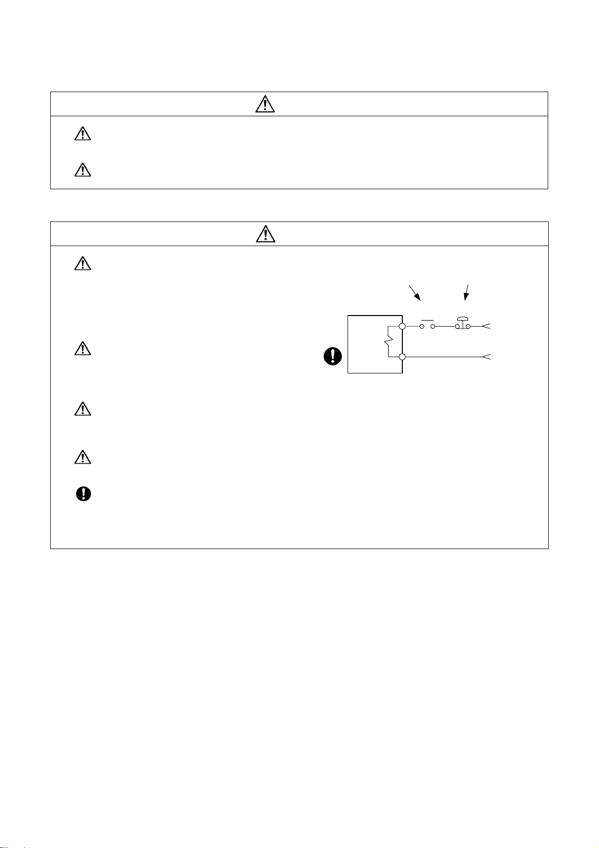
Do not mistake the direction of the surge
absorption diode to be installed on the DC relay
for the control output signal. If mistaken, the
Drive unit
COM
(24VDC)
Drive unit
COM
(24VDC)
signal will not be output due to fault in the drive
unit, and consequently the protective circuit,
such as emergency stop, could be disabled.
Control
output
signal
R
Control
output
signal
RA
Do not connect or disconnect the connection cables between each unit while the power is ON.
Do not connect or disconnect the PCBs while the power is ON.
Do not pull the cables when connecting/disconnecting it.
Securely tighten the cable connector fixing screw or fixing mechanism. Insufficient fixing could result
in deviation during operation.
Always treat the shield cables indicated in the Connection Manual with grounding measures such as
cable clamps.
Separate the signal wire from the drive line or power line when wiring.
Use wires and cables whose wire diameter, heat resistance level and bending capacity are
compatible with the system.
Ground the device according to the requirements of the country where the device is to be u s ed.
Wire the heat radiating fins and wires so that they do not contact.
When using the RS-232C device as a peripheral device, caution must be paid for connector
connection/disconnection.
Always use a double-OFF type AC power supply switch on the device side, and connect/disconnect
the connector with the AC power supply on the device side OFF.
NC unit
Device
RS-232C
Switch
AC socket
(3) Adjustments
CAUTION
(4) Usage
Check and adjust programs and each parameter before starting operation. Failure to observe this
could result in unpredictable operations depending on the machin e.
Do not make drastic adjustments or changes as the operation could become unstable.
Install an external emergency stop circuit so that the operation can be stopped and the power turns
OFF immediately when unforeseen situation occurs. A contactor, etc., is required in addition to the
shutoff function mounted in the controller.
Turn OFF the power immediately if any smoke, abnormal noise or odor is generated from the
controller, driv e unit or motor.
Only a qualified technician may disassemble or repair this product.
Do not alter.
Use a noise filter, etc. to reduce the effect of electromagnetic disturbances in the case where
electromagnetic disturbances could adversely affect the electronic devices used near the drive unit.
CAUTION
Use the drive unit, motor and each regenerative resistor with the designated combination. Failure to
observe this could result in fires or faults.
The combination of the motor and drive unit that can be used is determined. Be sure to check the
models of motor and drive unit before test operation.
The brakes (electromagnetic brakes) mounted in the servomotor are used for the purpose of
holding, and must not be used for normal braking. Also, do not run the motor with the motor brake
applied. Motor brake is used for the purpose of holding.
For the system running via a timing belt, install a brake on the machine side so that safety can be
ensured.
Be sure to confirm SERVO OFF (or READY OFF) when applying the electromagnetic brake. Also,
be sure to confirm SERVO ON prior to releasing the brake.
When using the DC OFF type electromagnetic brake, be sure to install a surge absorber on the
brake terminal.
Do not connect or disconnect the cannon plug while the electromagnetic brake’s power is ON. The
cannon plug pins could be damaged by sparks.
After changing programs/parameters, or after maintenance/inspection, always carry out a test
operation before starting actual operation.
r
CAUTION
Use the power that are complied with the power specification conditions (input voltage, input
frequency, tolerable instantaneous power failure time) indicated in each specifications manual.
When making detector cables, do not mistake connection. Failure to observe this could result in
malfunction, runaway or fire.
(5) Troubleshooting
Use a motor with electromagnetic brakes or
establish an external brake mechanism for the
purpose of holding; this serves as
countermeasures for possible hazardous
situation caused by power failure or product
fault.
Use a double circuit structure for the
electromagnetic brake’s operation circuit so
that the brakes will activate even when the
external emergency stop signal is issued.
The machine could suddenly restart when the power is restored after an instantaneous power
failure, so stay away from the machine. (Design the machine so that the operator safety can be
ensured even if the machine restarts.)
CAUTION
Shut off with motor
brake control output
Moto
Electromagnetic
brake
Shut off with CNC brake
control PLC output
MBR
EMG
24VDC
To secure the absolute position, do not shut off the servo drive unit’s control power supply when its
battery voltage drops (warning 9F) in the servo drive unit side.
If the battery voltage drop warning alarm occurs in the controller side, make sure to back up the
machining programs, tool data and parameters, etc. with the input/output device before replacing the
battery.
Depending on the level of voltage drop, memory loss could have happened. In that case, reload all
the data backed up before the alarm occurrence.
(6) Maintenance, inspection and part replacement
CAUTION
(7) Disposal
Periodically back up the programs, tool data and parameters to avoid potential data loss. Also, back
up those data before maintenance and inspections.
When replacing the battery on the controller side, the machining programs, tool data and para meters
should be backed up with the input/output device beforehand.
In case the memory is damaged in replacing the batteries, reload all the data backed up before
replacing the battery.
The electrolytic capacitor’s capacity will drop due to deterioration. To prevent secondary damage
due to capacitor’s faults, Mitsubishi recommends the electrolytic capacitor to be replaced approx.
every five years even when used in a normal environment. Contact the Service Center or Service
Station for replacements.
Do not perform a megger test (insulation resistance measurement) during inspection.
Do not replace parts or devices while the power is ON.
Do not short-circuit, charge, overheat, incinerate or disassemble the battery.
There may be a unit filled with substitute Freon in the heat radiating fins of the 37kW or smaller unit.
Be careful not to break the heat radiating fins during maintenance or replacement.
CAUTION
(8) General precautions
To explain the details, drawings given in the instruction manual, etc., may show the unit with the cover or
safety partition removed. When operating the product, always place the cover or partitions back to their
original position, and operate as indicated in the instruction manual, etc.
Take the batteries and backlights for LCD, etc., off from the controller, drive unit and motor, and
dispose of them as general industrial wastes.
Do not alter or disassemble controller, drive unit, or motor .
Collect and dispose of the spent batteries and the backlights for LC D according to the local laws.

CONTENTS
1. Introduction....................................................................................................................................1
2. System Configuration.................................................................................................................... 2
2.1 System Basic Configuration Drawing .........................................................................................2
2.2 General Connection Diagram.....................................................................................................3
2.3 List of Configuration Units...........................................................................................................4
2.3.1 Control Unit: FCU7-MU521/FCU7-MU522...........................................................................4
2.3.2 Display Unit: FCU7-DU120-12/FCU7-DU140-12 ................................................................. 4
2.3.3 Operation Panel I/O Unit: FCU7-DX7xx...............................................................................4
2.3.4 Keyboard Unit: FCU7-KB024/FCU7-KB044.........................................................................5
2.3.5 Remote I/O Unit:
FCUA-DX100/FCUA-DX110/FCUA-DX120/FCUA-DX140/FCUA-DX101/FCUA-DX111/
FCUA-DX121/FCUA-DX141 ................................................................................................. 5
2.3.6 Card-sized I/O Card: HR361/HR371/HR381/HR383............................................................5
2.3.7 External Power Supply Unit: PD25/PD27.............................................................................5
3. General Specifications (Environment Conditions).....................................................................6
3.1 Environment Conditions in Operation Panel...............................................................................6
3.2 Environment Specifications in Electric Cabinet...........................................................................7
3.3 Heat Radiation Countermeasures ..............................................................................................8
4. Outline Drawing ........................................................................................................................... 11
4.1 Control Unit............................................................................................................................... 11
4.1.1 FCU7-MU521/FCU7-MU522.............................................................................................. 11
4.2 Display Unit...............................................................................................................................13
4.2.1 FCU7-DU120-12 (8.4-type)................................................................................................13
4.2.2 FCU7-DU140-12 (10.4-type)..............................................................................................13
4.3 Operation Panel I/O Unit...........................................................................................................14
4.3.1 FCU7-DX710/FCU7-DX711................................................................................................14
4.3.2 FCU7-DX720/FCU7-DX721/FCU7-DX730/FCU7-DX731..................................................15
4.4 Keyboard Unit...........................................................................................................................16
4.4.1 FCU7-KB024 (8.4-type)......................................................................................................16
4.4.2 FCU7-KB044 (10.4-type)....................................................................................................16
4.5 Remote I/O Unit........................................................................................................................17
4.5.1 FCUA-DX100/FCUA-DX110/FCUA-DX120/FCUA-DX140/FCUA-DX101/FCUA-DX111/
FCUA-DX121/FCUA-DX141 ............................................................................................... 17
4.6 Card-sized I/O Card..................................................................................................................18
4.6.1 HR361/HR371/HR381/HR383............................................................................................18
5. Panel Cut Dimension Drawing / Installation Dimension Drawing ........................................... 20
5.1 Display Unit...............................................................................................................................20
5.1.1 FCU7-DU120-12 (8.4-type)................................................................................................20
5.1.2 FCU7-DU140-12 (10.4-type)..............................................................................................21
5.2 Operation Panel I/O Unit...........................................................................................................22
5.2.1 FCU7-DX710/FCU7-DX711/FCU7-DX720/FCU7-DX721/FCU7-730/FCU7-731 ...............22
5.3 Keyboard Unit...........................................................................................................................23
5.3.1 FCU7-KB024 (for 8.4-type).................................................................................................23
5.3.2 FCU7-KB044 (for 10.4-type)...............................................................................................24
5.4 External Power Supply Unit......................................................................................................26
5.4.1 PD25...................................................................................................................................26
5.4.2 PD27...................................................................................................................................26
5.4.3 Mounting Direction and Clearance.....................................................................................26
5.5 Remote I/O Unit........................................................................................................................27
5.5.1 FCUA-DX100/FCUA-DX110/FCUA-DX120/FCUA-DX140/FCUA-DX101/FCUA-DX111/
FCUA-DX121/FCUA-DX141........................................................................................................27

5.6 Manual Pulse Generator...........................................................................................................28
5.6.1 UFO-01-2Z9 .......................................................................................................................28
5.6.2 HD60 ..................................................................................................................................29
5.7 Synchronous Feed Encoder.....................................................................................................30
5.7.1 OSE-1024-3-15-68.............................................................................................................30
6. Connections of Control Unit.......................................................................................................31
6.1 Control Unit Connection System Drawing ................................................................................31
6.2 Connecting with Power Supply.................................................................................................32
6.2.1 When Using General-Purpose 24VDC Stabilized Power Supply ....................................... 32
6.2.2 When Using PD25/PD27 Power Supply Unit ..................................................................... 33
6.3 Connecting with Operation Panel I/O Unit................................................................................34
6.4 Connecting with Remote I/O Unit .............................................................................................35
6.5 Connecting with Card-sized I/O Card.......................................................................................35
6.6 Connecting with Optical Communication Servo Drive Unit.......................................................36
6.7 Connecting with RS-232C Device ............................................................................................ 38
6.8 Connecting with Skip Signal (Sensor) ...................................................................................... 40
6.9 Connecting with Synchronous Feed Encoder / Manual Pulse Generator.................................42
6.10 Connections of Emergency Stop Signal.................................................................................43
7. Connections of Operation Panel I/O Unit...................................................................................44
7.1 Operation Panel I/O Unit Connection System Drawing............................................................45
7.2 Connecting with Keyboard Unit ................................................................................................46
7.3 Connecting with Manual Pulse Generator (MPG).....................................................................47
7.3.1 Connecting with 5V Manual Pulse Generator (Maximum Cable Length: 20m)..................47
7.3.2 Connecting with 12V Manual Pulse Generator (Maximum Cable Length: 50m)................48
7.4 Connecting with Remote I/O Unit .............................................................................................49
7.5 Connecting with Card-sized I/O Card.......................................................................................49
7.6 Connecting with Machine Operation Panel...............................................................................50
7.6.1 Wiring the Input Side DI Connector (CG31/CG33/CG35) .................................................. 50
7.6.2 Wiring the Output Side DO Connector (CG32/CG34/CG36)..............................................50
7.6.3 Outline of Digital Signal Input Circuit..................................................................................51
7.6.4 Outline of Digital Signal Output Circuit...............................................................................53
7.6.5 Wiring for Sink Type Output (FCU7-DX710/DX720/DX730)...............................................54
7.6.6 Wiring for Source Type Output (FCU7-DX711/DX721/DX731)...........................................55
7.6.7 Outline of Analog Signal Output Circuit..............................................................................56
8. Connections of I/O Interface.......................................................................................................57
8.1 Types of I/O Interface ...............................................................................................................57
8.2 Connection of Remote I/O Unit.................................................................................................58
8.2.1 Outline of Remote I/O Unit .................................................................................................58
8.2.2 Names of Each Remote I/O Unit Section...........................................................................59
8.2.3 Setting of Station No. When Using Multiple Remote I/O Units...........................................60
8.2.4 Outline of Digital Signal Input Circuit..................................................................................62
8.2.5 Outline of Digital Signal Output Circuit...............................................................................64
8.2.6 Outline of Analog Signal Output Circuit..............................................................................65
8.2.7 Outline of Analog Signal Input Circuit.................................................................................66
8.2.8 Connection of FCUA-DX10 /14 Unit and Machine Control Signal.............................67
8.2.9 Connection of FCUA-DX14 Unit and Analog Input/Output Signal..................................69
8.2.10 Connection of FCUA-DX11 Unit and Machine Control Signal ....................................... 70
8.2.11 Connection of FCUA-DX12 Unit and Machine Control Signal...................................... 72
8.2.12 Cables ..............................................................................................................................74
8.3 Connecting with Card-sized I/O Card.......................................................................................75
8.3.1 Connection Example ..........................................................................................................75
8.3.2 DI/DO Type Specifications..................................................................................................76
8.3.3 AI/AO Type Specifications ..................................................................................................81
8.3.4 Precautions for Wiring........................................................................................................84

9. Basic Wiring for Servo Drive Unit...............................................................................................86
9.1 Basic Wiring for MDS-D/DH Series ..........................................................................................86
9.2 Basic Wiring for MDS-D-SVJ3/SPJ3 Series.............................................................................87
Appendix 1. EMC Installation Guidelines ...................................................................................... 88
1.1 Introduction...............................................................................................................................88
1.2 EMC Directives.........................................................................................................................88
1.3 EMC Measures......................................................................................................................... 89
1.4 Panel Structure.........................................................................................................................89
1.4.1 Measures for Control Panel Body.......................................................................................89
1.4.2 Measures for Door.............................................................................................................. 90
1.4.3 Measures for Power Supply ...............................................................................................90
1.5 Measures for Wiring in Panel....................................................................................................92
1.5.1 Precautions for Wiring in Panel..........................................................................................92
1.5.2 Shield Treatment of Cables................................................................................................92
1.6 EMC Countermeasure Parts.....................................................................................................93
1.6.1 Shield Clamp Fitting ...........................................................................................................93
1.6.2 Ferrite Core ........................................................................................................................93
1.6.3 Surge Absorber...................................................................................................................95
1.6.4. Selection of Stabilized Power Supply................................................................................97
Appendix 2. Cable............................................................................................................................98
2.1 F023/F024 Cable....................................................................................................................100
2.2 F034/F035 Cable....................................................................................................................101
2.3 F070 Cable.............................................................................................................................102
2.4 F110 Cable .............................................................................................................................102
2.5 F120 Cable.............................................................................................................................103
2.6 F170 Cable.............................................................................................................................103
2.7 F221 Cable.............................................................................................................................104
2.8 F320/F321 Cable....................................................................................................................104
2.9 F351 Cable.............................................................................................................................105
2.10 G011 Cable...........................................................................................................................106
2.11 G023/G024 Cable.................................................................................................................107
2.12 G300 Cable...........................................................................................................................108
2.13 G301 Cable...........................................................................................................................109
2.14 G380 Cable...........................................................................................................................109
2.15 G395 Cable........................................................................................................................... 110
2.16 G396 Cable........................................................................................................................... 110
2.17 G430 Cable............................................................................................................................111
2.18 FCUA-R030 Cable................................................................................................................ 112
2.19 FCUA-R050/R054 Cable...................................................................................................... 113
2.20 FCUA-R211 Cable................................................................................................................ 114
2.21 R300 Cable........................................................................................................................... 114
2.22 R301 Cable........................................................................................................................... 114
2.23 SH41 Cable .......................................................................................................................... 115
2.24 R-TM Terminator Connector ................................................................................................. 115
Appendix 3. Connectors................................................................................................................ 116
3.1 Connectors for Control Unit.................................................................................................... 116
3.1.1 Operation Panel I/O Unit Connecting Connector (CG71)................................................. 116
3.1.2 Skip Input Connector (SKIP) ............................................................................................ 116
3.1.3 Serial Communication Connector (SIO)........................................................................... 117
3.1.4 Encoder / Manual Pulse Generator Connecting Connector (ENC) .................................. 117
3.1.5 Optical Communication Connecting Connector (OPT)..................................................... 118
3.1.6 Remote I/O Unit Connecting Connector (RI01)................................................................ 118
3.1.7 Emergency Stop Input Connector (EMG)......................................................................... 118
3.1.8 24VDC Input Connector (DCIN)....................................................................................... 119

3.1.9 Ethernet Connector (LAN)................................................................................................ 119
3.2 Connectors for Operation Panel I/O Unit................................................................................ 120
3.2.1 Manual Pulse Generator Connecting Connector (MPG)..................................................120
3.2.2 Remote I/O Unit Connecting Connector (RIO3)...............................................................120
3.2.3 Machine Input/Output Connector (CG31/CG32/CG33/CG34/CG35/CG36).....................121
3.3 Connectors for Power Supply Unit..........................................................................................122
3.3.1 24VDC Output Connector (DCOUT) ................................................................................ 122
3.3.2 AC Power Input Connector (ACIN)...................................................................................122
3.3.3 ON/OFF Input Connector (ON/OFF) ................................................................................ 122
Appendix 4. Servo/Spindle Cable and Connector Specifications (MDS-D/DH Series)............ 123
4.1 Selection of Cable...................................................................................................................123
4.1.1 Cable Wire and Assembly................................................................................................123
4.2 Cable connection diagram......................................................................................................125
4.2.1 Battery cable.....................................................................................................................125
4.2.2 Power supply communication cable and connector ......................................................... 126
4.2.3 Servo detector cable.........................................................................................................127
4.2.4 Brake connecter (Brake connector for motor brake control output)..................................131
4.2.5 Spindle detector cable......................................................................................................132
4.2.6 C axis detector cable (For serial interface conversion unit APE391M connection)..........134
4.3 Main circuit cable connection diagram....................................................................................135
4.3.1 DRSV1 cable, DRSV2 cable ............................................................................................135
4.4 Connector outline dimension drawings...................................................................................136
4.4.1 Optical communication cable............................................................................................136
4.4.2 Battery connector .............................................................................................................138
4.4.3 Power supply communication connector.......................................................................... 139
4.4.4 Servo detector connector .................................................................................................140
4.4.5 Brake connector ...............................................................................................................143
4.4.6 Power connector...............................................................................................................144
4.4.7 Spindle detector connector............................................................................................... 146
Appendix 5. Servo/Spindle Cable and Connector Specifications (MDS-D-SVJ3/SPJ3 Series)148
5.1 Selection of Cable...................................................................................................................148
5.1.1 Cable wire and assembly .................................................................................................148
5.2 Cable connection diagram......................................................................................................150
5.2.1 Servo detector cable.........................................................................................................150
5.2.2 Spindle detector cable......................................................................................................153
5.2.3 C axis detector cable (For serial interface conversion unit APE391M connection)..........155
5.3 Connector outline dimension drawings...................................................................................156
5.3.1 Optical communication cable............................................................................................156
5.3.2 Servo detector connector .................................................................................................158
5.3.3 Brake connector ...............................................................................................................160
5.3.4 Power connector...............................................................................................................161
5.3.5 Drive unit side main circuit connector............................................................................... 162
5.3.6 Spindle detector connector............................................................................................... 164
Appendix 6. Precautions for Wiring 70 Series ............................................................................ 166
6.1 Connecting the Optical Fiber Cable........................................................................................166
6.1.1 Outline of Optical Fiber Cable and Names of Each Part..................................................166
6.1.2 Precautions for Handling Optical Fiber Cable ..................................................................166
6.1.3 Precautions for Laying Optical Fiber Cable......................................................................167
6.2 Precautions for Connecting Peripheral Devices.....................................................................167
6.3 Precautions for Connecting 24V Power Supply......................................................................167
6.4 Example of Handy Terminal Connections............................................................................... 168
6.4.1 Environment Specifications for Handy Terminal ...............................................................168
6.4.2 Outline Drawing of Handy Terminal..................................................................................169
6.4.3 Connections of Handy Terminal........................................................................................ 171

6.4.4 Explanation of Handy Terminal Signals and Connection Cables...................................... 172
Appendix 7. Transportation Restrictions for Lithium Batteries................................................. 175
7.1 Restriction for Packing............................................................................................................175
7.1.1 Target Products ................................................................................................................175
7.1.2 Handling by User..............................................................................................................176
7.1.3 Reference.........................................................................................................................177
7.2 Issuing Domestic Law of the United States for Primary Lithium Battery Transportation.........178
7.3 Example of Hazardous Goods Declaration List......................................................................179
Appendix 8. Precautions for Compliance to UL/c-UL Standards..............................................181
Appendix 9. Precautions for Use of Peripheral Devices and Commercially Available Devices
.........................................................................................................................................................182

1. Introduction
1. Introduction
This manual explains the items required for installing and connecting the MITSUBISHI CNC 70 Series.
Read this manual thoroughly and understand the product's functions and performance before starting to use.
This manual is written on the assumption that all option functions are added, but the actually delivered device
may not have all functions.
The unit names, cable names and various specifications are subject to change without notice. Please confirm
these before placing an order.
1
2. System Configuration
2. System Configuration
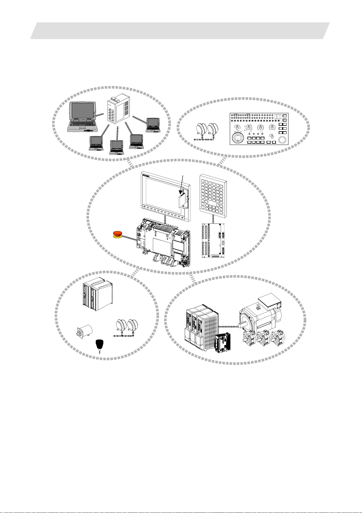
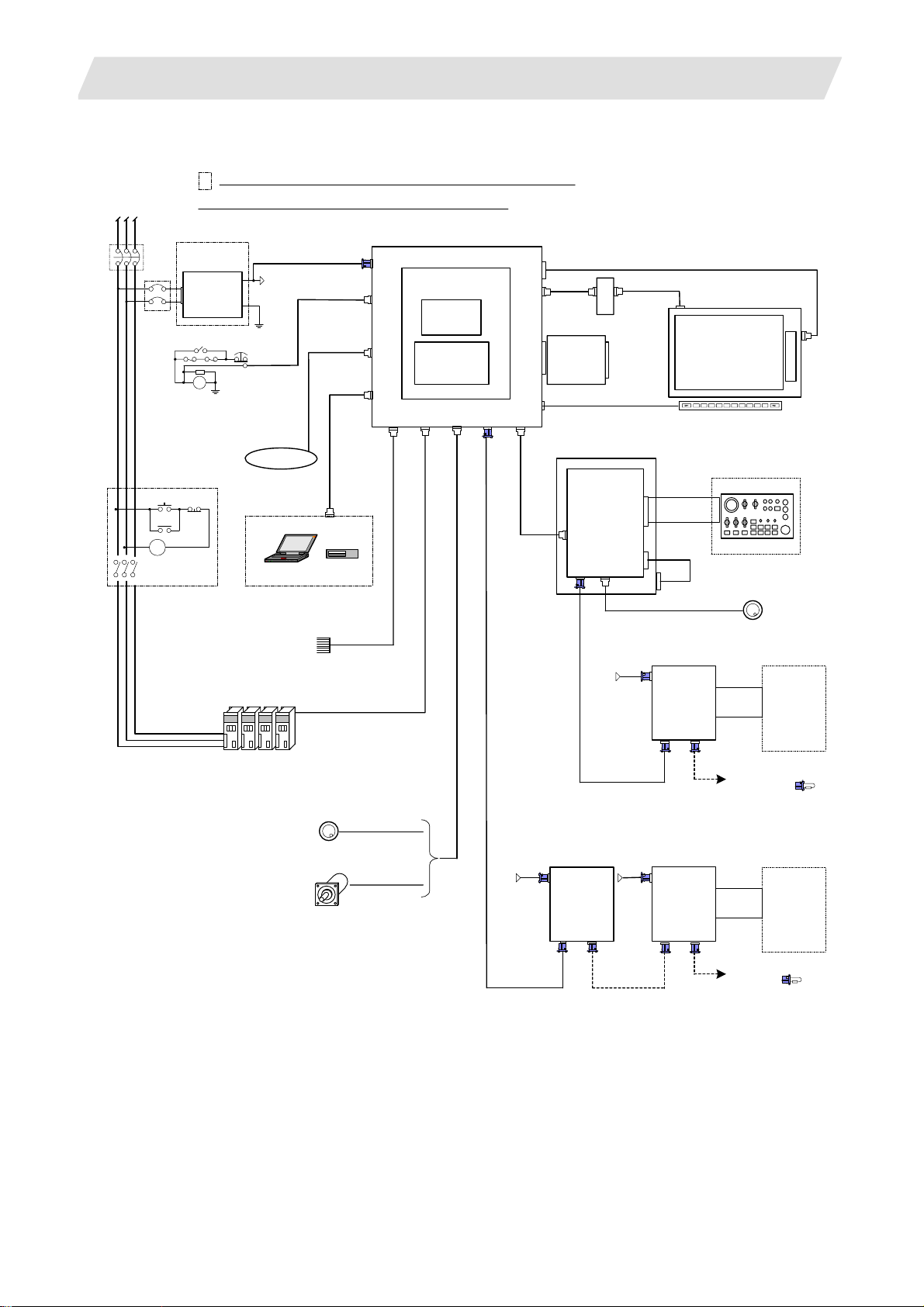
2.1 System Basic Configuration Drawing
Ethernet
hub
Personal
computer
Display unit
CF card I/F
2.1 System Basic Configuration Drawing
Machine operation panel
Manual pulse
generator
MF MCODEDATA
TF TCODEDATA
SW1 SW9 SW10 SW11 SW12 SW13 OVSL OVC SRN F1DSW8SW7SW6SW5SW4SW3SW2
10
1
-+
Keyboard unit
100
1000
5000
10000
50000
100000
AL1 AL2 AL3 AL4 TAP DEN OP SA MA
SFLED29LED30 LED31LED32 LED33LED34LED35LED36
RAP ID
STEP
R-P OINTRETURN
JOG
X
HANDLE
MEM
Y
MDI
Z
TAPE
4
1STREFERENCEPOSITION
+X +4+Z+Y
-X -4-Z-Y FEEDHOLDCYCLESTART
MANUAL FEEDRATE
100
52
27
20
10
REACHED
ON
DEGITALSWITCH
OFF
FIN
RESET
CUTTIN GFEEDRATEOVERRIDEMODE SELECTHANDLE/STEPMULTIPLICATION
100
520
110
720
270
90
80
120
1000
200
130
70
1400
140
60
2000
2700
3700
5200
7200
2
10000
1
mm/mi n
0
14000
4ZYX
50
40
30
20
10
0
RAPIDTRAVERSEOVERRIDE
50
25
1
MSTLOCK
MACHINELOCK
150
160
170
180
190
%
DRYRUN
SIN GLEBLOCK
200
100
EMERGENCYSTOP
Control unit
Operation panel
I/O unit
Synchronous feed
encoder
Emergency
stop switch
Remote I/O
unit
Manual pulse
generator
Servo/Spindle drive units
MDS-D/DH Series
MDS-D-SVJ3/SPJ3 Series
Skip
(Note 1) Control unit is mounted on the back side of the display unit with base plate.
(Note 2) Operation panel I/O unit is mounted on the back side of the keyboard unit.
Motors
2
2. System Configuration
2.2 General Connection Diagram
Dotted lines indicate the sections prepared by machin e too l builder.
RST
No-fuse breaker(NFB)
NFB
MC
MC
The name with brackets <> indicates the cable for the unit.
stabilized power
ACIN
ON OFF
MC
24VDC
supply
RA
DCOUT
FG
EMG
FG
24VDC
FG
Network
Sensor signals
Max. 8 pints
F070
F120
G300/G301
RS232C Device
Skip signal input
1ch
USER 2ch
1ch: F034
2ch: F035
FCUA-R030
G395/G396/G380
CNC control unit
FCU7-MU521/522
DCIN
Main card HN76x
EMG
LAN
Memory card
Expansion
SIO
OPT
SKIP ENC
HN4xx
card
HN75x
RIO1
LCD
INV
FRONT
MENU
CG71
G011
max. 0.5m
2.2 General Connection Diagram
<G097>
<F480>
Backlight inverter
Front CF
card
CF-70
Keyboard unit
FCU7-KB024/44
Operation panel
I/O unit
FCU7-DXxxx
CG71
RIO3 MPG
NCKB
24VDC
F070
Display unit
8.4-type FCU7-DU120-12
10.4-type FCU7-DU140-12
(VGA:640×480)
CG3x
F351
(G402)
12V:F320/F321
5V:F023/F024
Remote I/O unit
DCIN
FCUA-DX1xx
RIO2RIO1
Menu key
Machine operation panel
Manual pulse generator
2ch
DI-L/R
R300
Machine
control
relay/contact
Spindle/Servo Drive Units
MDS-D/DH/SVJ3/SPJ3
Manual pulse generator
Sync. Encoder
2ch
5V:G023/G024
1ch
FCUA-R050/054
24VDC 24VDC
F070
FCUA-R211
/SH41
FCUA-R211
/SH41
Remote I/O unit
DCIN
FCUA-DX1xx
RIO2
RIO1
F070
FCUA-R211
/SH41
Remote I/O unit
DCIN
FCUA-DX1xx
RIO2RIO1
To the next remote
I/O or terminator
DI-L/R
Machine
control
relay/contact
R300
To the next remote I/O
or terminator
3
2. System Configuration
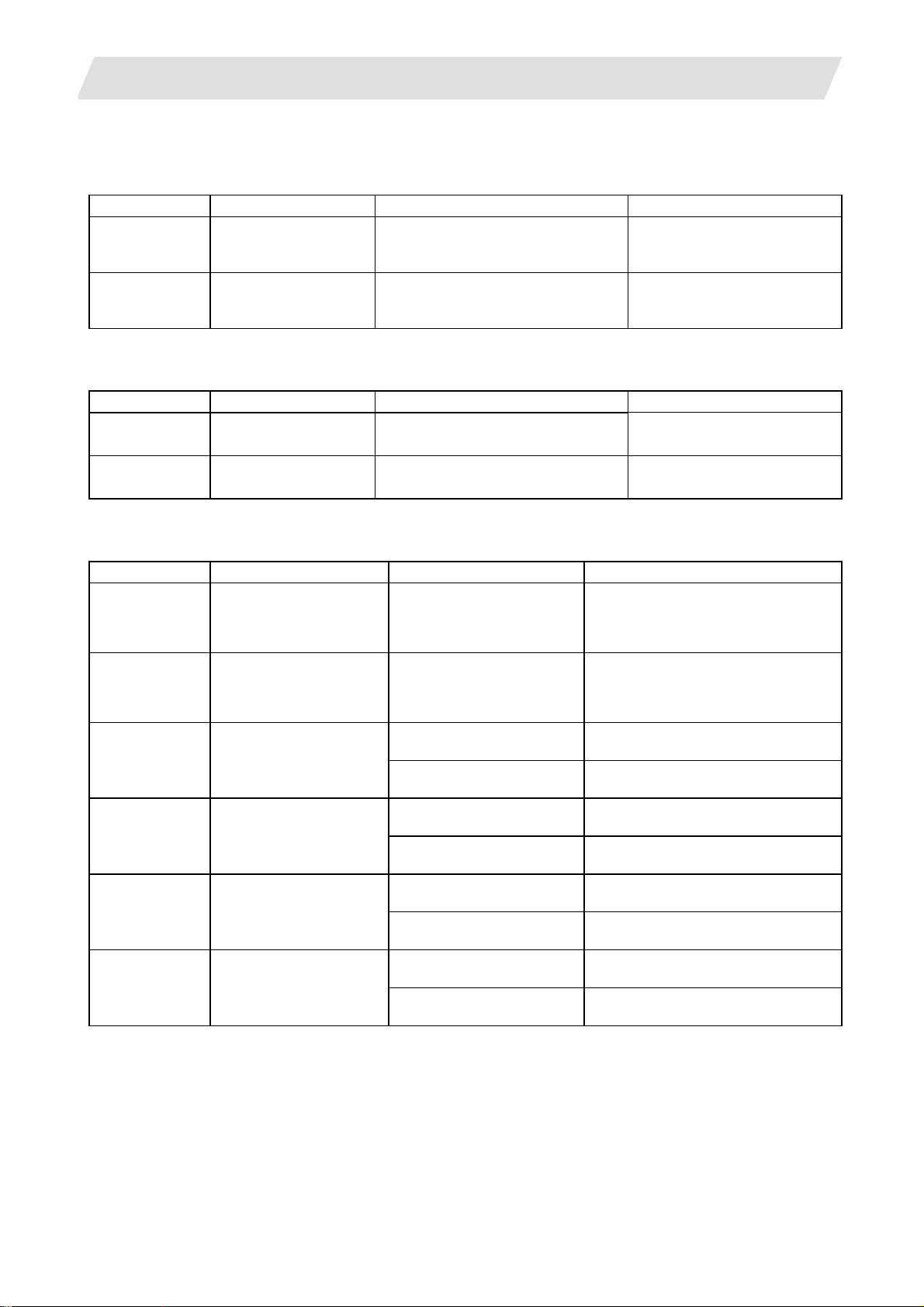
2.3 List of Configuration Units
2.3.1 Control Unit: FCU7-MU521/FCU7-MU522
Type Function Configuration element Details
FCU7-MU521 NC functions and
display controller
FCU7-MU522 NC functions and
display controller
2.3.2 Display Unit: FCU7-DU120-12/FCU7-DU140-12
Type Function Configuration element Details
FCU7-DU120-12 8.4-type color TFT LCD panel
Backlight inverter
FCU7-DU140-12 10.4-type color TFT LCD panel
Backlight inverter
2.3.3 Operation Panel I/O Unit: FCU7-DX7xx
Type Function Configuration element Details
FCU7-DX710 DI/DO Sink/source input
(insulation)
DO sink output
(non-insulation)
FCU7-DX711 DI/DO Sink/source input
(insulation)
DO source output
(non-insulation)
FCU7-DX720 DI/DO Sink/source input
(insulation)
DO sink output
(non-insulation)
Main control card (HN761)
Memory card (HN451)
Main control card (HN761)
Memory card (HN451)
Expansion card (HN751)
Base card (HN341) DI/DO = 64 points/64 points + MPG 2ch
Base card (HN351) DI/DO = 64 points/64 points + MPG 2ch
Base card (HN341) DI/DO = 64 points/64 points + MPG 2ch
Add-on card (HN361) DI/DO = 32 points/16 points + AO 1ch
2.3 List of Configuration Units
Export Trade Control Ordinance
and Foreign Trade Ordinance
noncompliant unit
Export Trade Control Ordinance
and Foreign Trade Ordinance
noncompliant unit
CF card I/F is normally equipped
with the control unit.
CF card I/F is normally equipped
with the control unit.
FCU7-DX721 DI/DO Sink/source input
(insulation)
DO source output
(non-insulation)
(insulation)
DO sink output
(non-insulation)
(insulation)
DO source output
(non-insulation)
Base card (HN351) DI/DO = 64 points/64 points + MPG 2ch
Add-on card (HN371) DI/DO = 32 points/16 points + AO 1ch
Base card (HN341) DI/DO = 64 points/64 points + MPG 2chFCU7-DX730 DI/DO Sink/source input
Add-on card (HN362) DI/DO = 32 points/32 points
Base card (HN342) DI/DO = 64 points/64 points + MPG 2chFCU7-DX731 DI/DO Sink/source input
Add-on card (HN372) DI/DO = 32 points/32 points
(Note 1) Operation panel I/O unit is mounted on the back side of the keyboard unit FCU7-KB024/KB044.
(Note 2) Operation panel I/O unit for 700 Series is not available.
4
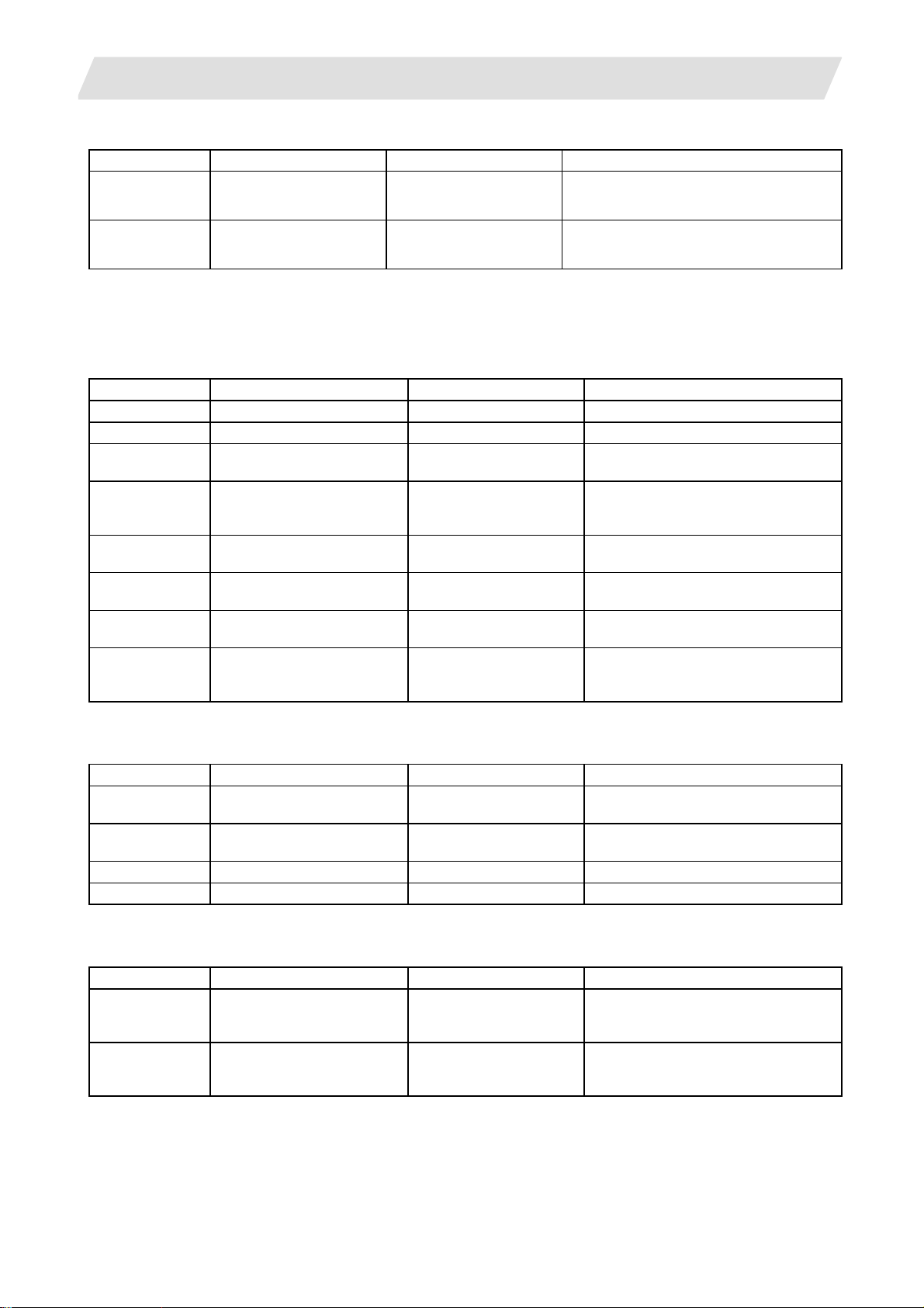
2. System Configuration
2.3 List of Configuration Units
2.3.4 Keyboard Unit: FCU7-KB024/FCU7-KB044
Type Function Configuration element Details
FCU7-KB024 8.4-type display keyboard Escutcheon, key switch Connect with G011 cable from control unit.
Mounting method: Mount on front panel
FCU7-KB044 10.4-type display keybo ard Escutcheon, key switch Connect with G011 cable from control unit.
Mounting method: Mount on front panel
2.3.5 Remote I/O Unit: FCUA-DX100/FCUA-DX110/FCUA-DX120/FCUA-DX140/FCUA-DX101/FCUA-DX111/ FCUA-DX121/FCUA-DX141
Type Function Configuration element Details
FCUA-DX100 Sink/source input + sink output RX31 1 DI/DO = 32 points/32 points
FCUA-DX110 Sink/source input + sink output RX311+RX321-1 DI/DO = 64 points/48 points
FCUA-DX120 Sink/source input + sink output
+ analog output
FCUA-DX140 Sink/source input + sink output
+ analog input/output
FCUA-DX101 Sink/source input + source
output
FCUA-DX111 Sink/source input + source
output
FCUA-DX121 Sink/source input + source
output + analog output
FCUA-DX141 Sink/source input + source
output + analog input/output
RX311+RX321 DI/DO = 64 points/48 points
+ analog output 1 point
RX311+RX341 DI/DO = 32 points/32 points
+ analog input 4 points
+ analog output 1 point
RX312 DI/DO = 32 points/32 points
RX312+RX322-1 DI/DO = 64 points/48 points
RX312+RX322 DI/DO = 64 points/48 points
+ analog output 1 point
RX312+RX341 DI/DO = 32 points/32 points
+ analog input 4 points
+ analog output 1 point
2.3.6 Card-sized I/O Card: HR361/HR371/HR381/HR383
Type Function Configuration element Details
HR361 DI16 (sink/source)
+DO16 (sink)
HR371 DI32 (sink/source)
+DO16 (source)
HR381 AO x 1 HR381 AO x 1
HR383 AI x 4+AO x 1 HR383 AI x 4+AO x 1
HR361 DI/DO = 16 points/16 points
HR371 DI/DO = 16 points/16 points
2.3.7 External Power Supply Unit: PD25/PD27
Type Function Configuration element Details
PD25 External power supply with
power supply ON/OFF
function
PD27 External power supply with
power supply ON/OFF
function
Power supply card
Case set
Power supply card
Case set
Input 200VAC
Output 24VDC (3A)
Input 200V to 400VAC
Output 24VDC (8A)
5
3. General Specifications (Environment Conditions)
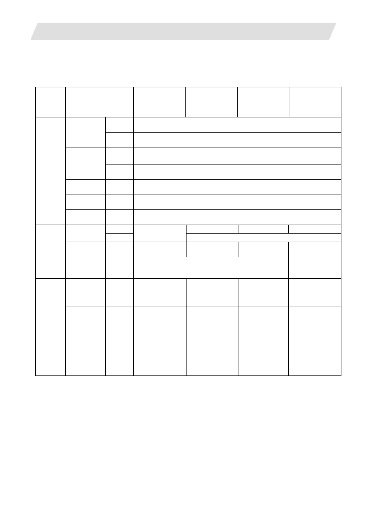
3.1 Environment Conditions in Operation Panel
3. General Specifications (Environment Conditions)
3.1 Environment Conditions in Operation Panel
Unit name Control unit Display unit Keyboard unit
Item
Type FCU7-MU521/522
During
operation
During
storage
Long
term
Short
term
4.9m/s
29.4m/s
No corrosive gases, dust or oil mist
3.3/12VDC 5VDC 3.3/5VDC
2.5A – –
20ms –
(mm)
24VDC ± 5%, ripple
noise 200mV (P-P)
235(width)
×173(height)
× 73 (depth)
(Depth from the
plate mounting
surface: 60)
General
specifications
Required
power
specifications
Others
Ambient
temperature
Ambient
humidity
Vibration
resistance
Shock
resistance
Working
atmosphere
Power voltage
Power
capacity
Instantaneous
stop tolerance
time
Heating value (Max.) 12W
Mass (kg) 1.0
Outline
dimension
(Note 1) The period is within one month.
(Note 2) For the current value of the I/O circuit, calculate with the number of points used and load.
(Note 3) For the heating value of the I/O circuit, calculate with the number of points used.
FCU7-DU120-12/
140-2
-20 to 60°C
10 to 75% RH (with no dew condensation)
10 to 95% RH (with no dew condensation) (Note 1)
2
or less (during operation)
2
or less (during operation)
FCU7-DU120-12:
10W
FCU7-DU140-2:
12W
FCU7-DU120-12:
1.5
FCU7-DU140-2:
2.0
FCU7-DU120-12:
260(width) ×
200(height)
FCU7-DU140-2:
290(width) ×
220(height)
FCU7-KB024/44
0 to 55°C
(Provided by the control unit)
1.0W
0.8 0.4
FCU7-KB024:
140(width) ×
200(height)
FCU7-KB044:
140(width) ×
220(height)
Operation panel
I/O unit
FCU7-DX71/
72/73
–
(Note 2)
Control section:
5.0W
(Note 3)
120(width) ×
180(height)
6
3. General Specifications (Environment Conditions)
3.2 Environment Specifications in Electric Cabinet
3.2 Environment Specifications in Electric Cabinet
Item
General
specifications
Required
Power
specification
Others
Unit name
Type FCUA-DX10 FCUA-DX11 FCUA-DX12 FCUA-DX14
Ambient
temperature
Ambient
humidity
Vibration resistance 4.9m/s2 or less (during operation)
Shock resistance 29.4m/s2 or less (during operation)
Working atmosphere No corrosive gases, dust
Input power voltage 24VDC±5% Ripple noise 200mV (P-P)
Power capacity 24V 0.7A (Note 2) 24V 1.5A (Note 2) 24V 0.7A (Note 2)
Instantaneous stop
tolerance time
Heating value (Max.) 25W (Note 3) 30W (Note 3) 30W (Note 3)
Mass 0.5kg 0.6kg 0.6kg 0.6kg
(Note 1) The period is within one month.
(Note 2) Amount consumed by control circuit
(Note 3) Differs according to the number of machine input operation points and the load and number of
points connected to the machine output. The maximum value applies when all points are ON.
Remote I/O unit
During
operation
During
storage
Long term 10 to 75% RH (with no dew condensation)
Short term 10 to 95% RH (with no dew condensation) (Note 1)
0 to 55°C
–20 to 60°C
—
7
3. General Specifications (Environment Conditions)
3.3 Heat Radiation Countermeasures
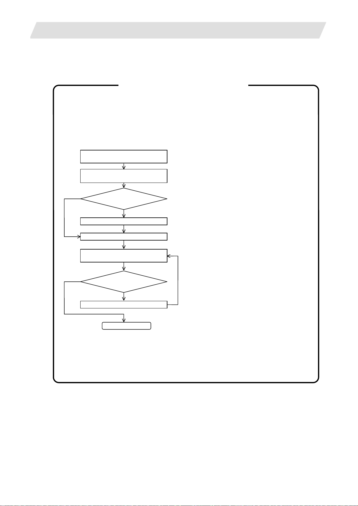
3.3 Heat Radiation Countermeasures
Please refer to the following method for heat radiation countermeasures.
<Hypothetical conditions>
(1) Average internal temperature of operation panel: T ≤ 55°C
(2) Peripheral temperature of operation panel : Ta ≤ 0°C to 45°C
(3) Internal temperature rise value : ΔT = T–Ta (max) = 10°C
Example of heat radiation countermeasures
Procedures for heat design and verification
Calculate total heat radiation of each
mounted unit (W)
Calculate cooling capacity of
operation panel (W1)
W ≤ W1
≤10°C
ΔT
Comparison of W and W1
W>W1
Selection of heat exchanger
Mounting design
Collection of internal temperature rise
distribution data
Evaluation
ΔT>10°C
Improvements
<Supplement>
(1) Refer to "3. General Specification" for the heat
generated by each unit.
(2) Enclosed cabinet (thin steel plate) cooling
capacity calculation equation
W1 = U × A × ΔT
U: 6 W/m
A: Effective heat radiation area (m
2
°C
2
)
ΔT: Internal temperature rise value (10°C)
(Area where heat can be radiated from
operation panel)
<Caution>
2
8 W/m
°C can be applied only when the
operation panel is so small that the internal
temperature stays uniform.
(3) Points of caution for heat radiation
countermeasures when designing mounting
state
* Consider convection in operation panel
(eliminate heat spots)
* Collect hot air at suction port of heat
exchanger in operation panel.
(4) Criterion for internal temperature rise
distribution data
Completion
ΔT (average value) ≤ 10°C
ΔTmax (maximum value) ≤ 15°C
R (inconsistency ΔTmax – ΔTmin) ≤ 6°C
(Evaluate existence of heat spots)
8
3. General Specifications (Environment Conditions)
3.3 Heat Radiation Countermeasures
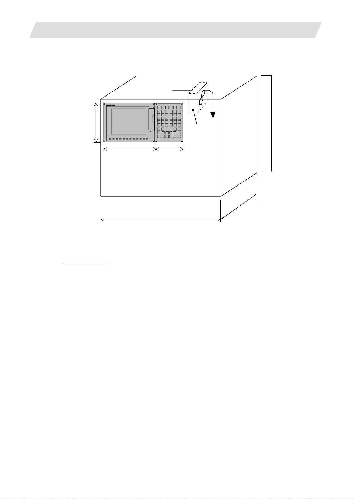
The following shows an example of calculation applied to heat radiation countermeasures for the operation
panel. Because heat will accumulate in the upper portions of the unit, install an agitating fan as required.
Display unit
200
260 140
600
(Agitating fan)
<Calculation example of heating value in operation panel>
(1) Calculation of unit heating value
Heating value (W)
Total heating value of units (W):
28W (= control unit + display unit + keyboard unit + operation panel I/O unit)
Total heating value (W) by machine input (D1):
5.6W (= 24V;
total heating value when the 32 points are simultaneously turned ON × 7.3mA × 32)
... 24V; current consumption per point of the operation panel I/O unit DI ÷ 3.3kΩ ≒ 7.3mA
Total heating value W = 33.6W (28 + 5.6)
500
120
9

3. General Specifications (Environment Conditions)
(2) Calculation of operation panel cooling capacity
Tolerance value for temperature rise (Δt)
Panel internal temperature (according to each unit’s specification) T ≤ 55C°
Panel peripheral temperature (according to machine’s specification) Ta ≤ 45C°
Tolerance value for internal temperature rise ΔT = 10C° (T – Ta)
Heat radiation area (A)
The surface of the molded unit, which has lower radiation capacity than the metal plate surface,
should be excluded for the heat radiation area in principle.
The bottom of the operation panel, which has difficulty in radiating due to the temperature
distribution, should also be excluded for the heat radiation area in principle.
Heat radiation area A = 0.71mm
(≒ 0.6 × 0.12 + 0.6 × 0.5 × 2 – (0.2 6 + 0.14) × 0.2 + 0.12 × 0.5 × 2)
(Top surface) (Front, rear surface) (Unit surface) (Both sides surface)
Operation panel cooling capacity (W1)
Calculate the cooling capacity to keep the temperature rise in the operation panel less than 10°C.
Cooling capacity W1 = 42.6W (6 × A × ΔT)
(3) Comparison of heating value and operation panel cooling capacity
The operation panel cooling capacity is over the heating value, which presumed no need to install
the heat exchanger.
(4) Confirmation with the actual machine
The result of the calculation above is only a rough indication. The actual temperature rise may differ
according to the structure of the operation panel.
Be sure to confirm the temperature rise value in the operation panel when the machine is run ning.
2
3.3 Heat Radiation Countermeasures
10
4. Outline Drawing
4. Outline Drawing
4.1 Control Unit
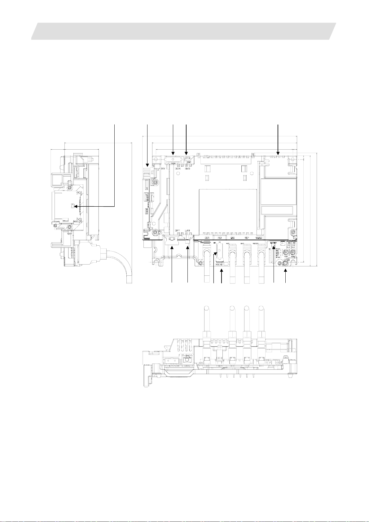
4.1.1 FCU7-MU521/FCU7-MU522
21
100
52
(2)
(3) (4)
235
220
208
4.1 Control Unit
(5) (1)
6
6
156 168 173
(6)
(7)
(8)
(11) (12) (13)
(10)
(9)
(14)
(15)
11

4. Outline Drawing
4.1 Control Unit
Explanation of connector functions
Connec-
No.
tor name
(1) CF Front CF card I/F (9) RIO1 Remote IO unit I/F
(2) INV
(3) DCIN 24VDC input
(4) EMG External emergency stop input (12) SKIP Skip input 8ch
(5) LCD Display unit signal connector (13) SIO RS-232C communication I/F 2ch
(6) OPT Optical servo communication I/F (14) BATTERY Battery (Q6BAT) connector
(7) LAN LAN communication I/F (15) FG FG terminal block
(8) CG71 Operation panel I/O unit I/F
Display unit backlight
Inverter connector
Function No.
Connector
name
(10) MENUKEY Menu key I/F
(1 1) ENC
Encoder input 1ch
(5V manual pulse generator input 2ch)
Function
12

4. Outline Drawing
4.2 Display Unit
4.2.1 FCU7-DU120-12 (8.4-type)
260
200
20 110
4.2 Display Unit
(Space required for wiring)
(Note 1) The above side view shows the state with the control unit mounted.
(Note 2) Consider the heat radiation space for the upper space.
(Note 3) Consider the minimum radius value of optical cable for the bottom space.
4.2.2 FCU7-DU140-12 (10.4-type)
290
220
20 110 (Space required for wiring)
(Note 1) The above side view shows the state with the control unit mounted.
(Note 2) Consider the heat radiation space for the upper space.
(Note 3) Consider the minimum radius value of optical cable for the bottom space.
13
Loading...