


Descriptive Technical
Documentation
- Model-dependent -
DTD no. 11-4800
Model(s): W 4840, W 4800
22.12.2006, US_am |
This information should not be duplicated or passed on without Miele approval. All rights reserved. |

This information should not be duplicated or passed on without Miele approval. All rights reserved. |
22.12.2006, US_am |

|
Descriptive Technical Documentation |
DTD no. 11-4800 |
1 |
Contents
General Information
A Warning and Safety Instructions
B Modification History
CTechnical Data
DLayout of Electrical Components
Function Groups
010 |
Housing, Lid, Secure Transport |
|
|
|
1 |
Technical Data . . . . . . . . . . . . . . . . . . . . . . . . . . . . . . . . . . . . . |
010-2 |
|
3 |
Fault Repair . . . . . . . . . . . . . . . . . . . . . . . . . . . . . . . . . . . . . . . . |
010-3 |
|
3.1 |
Vibrations during spin cycle. . . . . . . . . . . . . . . . . . . . . . . . . . . . . . |
010-3 |
|
4 |
Service. . . . . . . . . . . . . . . . . . . . . . . . . . . . . . . . . . . . . . . . . . . . . |
010-4 |
|
4.1 |
Lid – Remove . . . . . . . . . . . . . . . . . . . . . . . . . . . . . . . . . . . . . . . . . |
010-4 |
|
4.2 |
Front panel – Remove . . . . . . . . . . . . . . . . . . . . . . . . . . . . . . . . . . |
010-5 |
|
4.3 |
Float switch (B8). . . . . . . . . . . . . . . . . . . . . . . . . . . . . . . . . . . . . . . |
010-6 |
020 |
Door, Magnet, Lock |
|
|
|
1 |
Technical Data . . . . . . . . . . . . . . . . . . . . . . . . . . . . . . . . . . . . . |
020-2 |
|
2 |
Function . . . . . . . . . . . . . . . . . . . . . . . . . . . . . . . . . . . . . . . . . . . |
020-3 |
|
2.1 |
Pull door lock (A2) . . . . . . . . . . . . . . . . . . . . . . . . . . . . . . . . . . . . . |
020-3 |
|
2.1.1 |
Electromagnetic door lock . . . . . . . . . . . . . . . . . . . . . . . . . . . . . . . |
020-3 |
|
2.1.2 |
Safety requirements . . . . . . . . . . . . . . . . . . . . . . . . . . . . . . . . . . . . |
020-3 |
|
3 |
Fault Repair . . . . . . . . . . . . . . . . . . . . . . . . . . . . . . . . . . . . . . . . |
020-4 |
|
3.1 |
Door lock (A2) does not lock . . . . . . . . . . . . . . . . . . . . . . . . . . . . . |
020-4 |
|
4 |
Service. . . . . . . . . . . . . . . . . . . . . . . . . . . . . . . . . . . . . . . . . . . . . |
020-5 |
|
4.1 |
Door lock (A2) – Open manually . . . . . . . . . . . . . . . . . . . . . . . . . . |
020-5 |
|
4.2 |
Door lock (A2) – Remove. . . . . . . . . . . . . . . . . . . . . . . . . . . . . . . . |
020-6 |
|
4.3 |
Door porthole, door latch and hinge – Remove . . . . . . . . . . . . . . |
020-7 |
030 |
Suds container, Drum, Bearing, Heater element |
|
|
|
1 |
Technical Data . . . . . . . . . . . . . . . . . . . . . . . . . . . . . . . . . . . . . |
030-2 |
|
2 |
Function . . . . . . . . . . . . . . . . . . . . . . . . . . . . . . . . . . . . . . . . . . . |
030-3 |
|
2.1 |
Foam sensing . . . . . . . . . . . . . . . . . . . . . . . . . . . . . . . . . . . . . . . . . |
030-3 |
|
2.1.1 |
Foam when heating during the main wash cycle . . . . . . . . . . . . . |
030-3 |
|
2.1.2 |
Foam at rinse cycle water intake (in the drum vent or in the |
|
|
|
siphon) . . . . . . . . . . . . . . . . . . . . . . . . . . . . . . . . . . . . . . . . . . . . . . |
030-3 |
22.12.2006, US_am |
This information should not be duplicated or passed on without Miele approval. All rights reserved. |

|
|
Descriptive Technical Documentation |
|
2 |
|
DTD no. 11-4800 |
|
|
2.1.3 |
Foam during spin cycle (water sheet) . . . . . . . . . . . . . . . . . . . . . . |
030-3 |
|
2.2 |
Light in the door concertina seal . . . . . . . . . . . . . . . . . . . . . . . . . . |
030-4 |
|
2.3 |
Heater . . . . . . . . . . . . . . . . . . . . . . . . . . . . . . . . . . . . . . . . . . . . . . . |
030-4 |
|
4 |
Service. . . . . . . . . . . . . . . . . . . . . . . . . . . . . . . . . . . . . . . . . . . . . |
030-5 |
|
4.1 |
Temperature sensor (NTC resistor, R30) . . . . . . . . . . . . . . . . . . . |
030-5 |
|
4.2 |
Air trap – Clean. . . . . . . . . . . . . . . . . . . . . . . . . . . . . . . . . . . . . . . . |
030-5 |
|
4.3 |
Door sealing ring – Replace . . . . . . . . . . . . . . . . . . . . . . . . . . . . . |
030-5 |
040 |
Water intake |
|
|
|
1 |
Technical Data . . . . . . . . . . . . . . . . . . . . . . . . . . . . . . . . . . . . . |
040-2 |
|
2 |
Function . . . . . . . . . . . . . . . . . . . . . . . . . . . . . . . . . . . . . . . . . . . |
040-3 |
|
2.1 |
Float switch (B8). . . . . . . . . . . . . . . . . . . . . . . . . . . . . . . . . . . . . . . |
040-3 |
|
2.2 |
Hot water intake control . . . . . . . . . . . . . . . . . . . . . . . . . . . . . . . . . |
040-3 |
|
2.3 |
Automatic load control / Intelligent water intake (IWE) . . . . . . . . |
040-3 |
|
2.4 |
Water intake monitoring – water control system (WCS) . . . . . . . |
040-4 |
|
2.5 |
Water overflow monitoring . . . . . . . . . . . . . . . . . . . . . . . . . . . . . . . |
040-4 |
|
2.6 |
Flow meter (B3/4) . . . . . . . . . . . . . . . . . . . . . . . . . . . . . . . . . . . . . . |
040-4 |
|
2.7 |
Water path control unit, motor water path control unit (M24). . . . |
040-5 |
|
4 |
Service. . . . . . . . . . . . . . . . . . . . . . . . . . . . . . . . . . . . . . . . . . . . . |
040-6 |
|
4.1 |
Flow meter (B3/4) . . . . . . . . . . . . . . . . . . . . . . . . . . . . . . . . . . . . . . |
040-6 |
050 |
Water drain |
|
|
|
1 |
Technical Data . . . . . . . . . . . . . . . . . . . . . . . . . . . . . . . . . . . . . |
050-2 |
|
2 |
Function . . . . . . . . . . . . . . . . . . . . . . . . . . . . . . . . . . . . . . . . . . . |
050-3 |
|
2.1 |
Water drain monitoring. . . . . . . . . . . . . . . . . . . . . . . . . . . . . . . . . . |
050-3 |
060 |
Drive |
|
|
|
1 |
Technical Data . . . . . . . . . . . . . . . . . . . . . . . . . . . . . . . . . . . . . |
060-2 |
|
2 |
Function . . . . . . . . . . . . . . . . . . . . . . . . . . . . . . . . . . . . . . . . . . . |
060-3 |
|
2.1 |
Spin lock . . . . . . . . . . . . . . . . . . . . . . . . . . . . . . . . . . . . . . . . . . . . . |
060-3 |
|
2.2 |
Toothed V-belt . . . . . . . . . . . . . . . . . . . . . . . . . . . . . . . . . . . . . . . . |
060-3 |
|
2.3 |
Motor overheating protection. . . . . . . . . . . . . . . . . . . . . . . . . . . . . |
060-3 |
|
2.4 |
Tachogenerator . . . . . . . . . . . . . . . . . . . . . . . . . . . . . . . . . . . . . . . |
060-4 |
|
3 |
Fault Repair . . . . . . . . . . . . . . . . . . . . . . . . . . . . . . . . . . . . . . . . |
060-5 |
|
3.1 |
Drum drive defective . . . . . . . . . . . . . . . . . . . . . . . . . . . . . . . . . . . |
060-5 |
|
4 |
Service. . . . . . . . . . . . . . . . . . . . . . . . . . . . . . . . . . . . . . . . . . . . . |
060-6 |
|
4.1 |
Tachogenerator . . . . . . . . . . . . . . . . . . . . . . . . . . . . . . . . . . . . . . . |
060-6 |
|
4.2 |
Toothed V-belt – Mount . . . . . . . . . . . . . . . . . . . . . . . . . . . . . . . . . |
060-6 |
|
4.3 |
Drive MXT 40 . . . . . . . . . . . . . . . . . . . . . . . . . . . . . . . . . . . . . . . . . |
060-7 |
070 |
Fascia panel, Control electronic |
|
|
|
1 |
Technical Data . . . . . . . . . . . . . . . . . . . . . . . . . . . . . . . . . . . . . |
070-2 |
|
2 |
Function . . . . . . . . . . . . . . . . . . . . . . . . . . . . . . . . . . . . . . . . . . . |
070-3 |
|
2.1 |
Child safety sensor. . . . . . . . . . . . . . . . . . . . . . . . . . . . . . . . . . . . . |
070-3 |
|
2.2 |
Action after a power failure . . . . . . . . . . . . . . . . . . . . . . . . . . . . . . |
070-3 |
|
2.3 |
Programming function (HY IV E). . . . . . . . . . . . . . . . . . . . . . . . . . |
070-4 |
|
2.3.1 |
Water Plus . . . . . . . . . . . . . . . . . . . . . . . . . . . . . . . . . . . . . . . . . . . |
070-4 |
|
2.3.2 |
Gentle cycle . . . . . . . . . . . . . . . . . . . . . . . . . . . . . . . . . . . . . . . . . . |
070-4 |
This information should not be duplicated or passed on without Miele approval. All rights reserved. |
22.12.2006, US_am |

|
Descriptive Technical Documentation |
|
DTD no. 11-4800 |
|
3 |
2.3.3 |
Suds cooling . . . . . . . . . . . . . . . . . . . . . . . . . . . . . . . . . . . . . . . . . . |
070-4 |
2.3.4 |
Memory . . . . . . . . . . . . . . . . . . . . . . . . . . . . . . . . . . . . . . . . . . . . . . |
070-4 |
2.3.5 |
Buzzer. . . . . . . . . . . . . . . . . . . . . . . . . . . . . . . . . . . . . . . . . . . . . . . |
070-4 |
2.3.6 |
Language . . . . . . . . . . . . . . . . . . . . . . . . . . . . . . . . . . . . . . . . . . . . |
070-4 |
2.3.7 |
Contrast . . . . . . . . . . . . . . . . . . . . . . . . . . . . . . . . . . . . . . . . . . . . . |
070-4 |
2.3.8 |
Standby. . . . . . . . . . . . . . . . . . . . . . . . . . . . . . . . . . . . . . . . . . . . . . |
070-4 |
2.3.9 |
Water intake . . . . . . . . . . . . . . . . . . . . . . . . . . . . . . . . . . . . . . . . . . |
070-5 |
2.3.10 |
Max. water level . . . . . . . . . . . . . . . . . . . . . . . . . . . . . . . . . . . . . . . |
070-5 |
2.3.11 |
Country version . . . . . . . . . . . . . . . . . . . . . . . . . . . . . . . . . . . . . . . |
070-5 |
2.3.12 |
Max. spin speed . . . . . . . . . . . . . . . . . . . . . . . . . . . . . . . . . . . . . . . |
070-5 |
2.3.13 |
Load automatic. . . . . . . . . . . . . . . . . . . . . . . . . . . . . . . . . . . . . . . . |
070-5 |
2.3.14 |
Imbalance values . . . . . . . . . . . . . . . . . . . . . . . . . . . . . . . . . . . . . . |
070-5 |
2.3.15 |
Central unit . . . . . . . . . . . . . . . . . . . . . . . . . . . . . . . . . . . . . . . . . . . |
070-5 |
2.3.16 |
Heater output . . . . . . . . . . . . . . . . . . . . . . . . . . . . . . . . . . . . . . . . . |
070-5 |
2.3.17 |
Low water pressure . . . . . . . . . . . . . . . . . . . . . . . . . . . . . . . . . . . . |
070-5 |
2.3.18 |
Allergy . . . . . . . . . . . . . . . . . . . . . . . . . . . . . . . . . . . . . . . . . . . . . . . |
070-6 |
2.3.19 |
Sensor controlled rinse cycle. . . . . . . . . . . . . . . . . . . . . . . . . . . . . |
070-6 |
2.3.20 |
Temperature . . . . . . . . . . . . . . . . . . . . . . . . . . . . . . . . . . . . . . . . . . |
070-6 |
2.3.21 |
Current volume meter (VSZ) . . . . . . . . . . . . . . . . . . . . . . . . . . . . . |
070-6 |
2.3.22 |
Keypad tone . . . . . . . . . . . . . . . . . . . . . . . . . . . . . . . . . . . . . . . . . . |
070-6 |
2.3.23 |
Reset . . . . . . . . . . . . . . . . . . . . . . . . . . . . . . . . . . . . . . . . . . . . . . . . |
070-6 |
2.3.24 |
Imbalance sensor. . . . . . . . . . . . . . . . . . . . . . . . . . . . . . . . . . . . . . |
070-7 |
2.3.25 |
Water valves . . . . . . . . . . . . . . . . . . . . . . . . . . . . . . . . . . . . . . . . . . |
070-7 |
2.3.26 |
Display . . . . . . . . . . . . . . . . . . . . . . . . . . . . . . . . . . . . . . . . . . . . . . |
070-7 |
2.3.27 |
Appliance . . . . . . . . . . . . . . . . . . . . . . . . . . . . . . . . . . . . . . . . . . . . |
070-7 |
2.3.28 |
Load indication . . . . . . . . . . . . . . . . . . . . . . . . . . . . . . . . . . . . . . . . |
070-7 |
2.3.29 |
Drum light . . . . . . . . . . . . . . . . . . . . . . . . . . . . . . . . . . . . . . . . . . . . |
070-8 |
2.3.30 |
Brightness. . . . . . . . . . . . . . . . . . . . . . . . . . . . . . . . . . . . . . . . . . . . |
070-8 |
2.3.31 |
Fascia panel type . . . . . . . . . . . . . . . . . . . . . . . . . . . . . . . . . . . . . . |
070-8 |
2.3.32 |
Hygiene. . . . . . . . . . . . . . . . . . . . . . . . . . . . . . . . . . . . . . . . . . . . . . |
070-8 |
2.3.33 |
Prewash at heavy soil . . . . . . . . . . . . . . . . . . . . . . . . . . . . . . . . . . |
070-9 |
2.3.34 |
Chlorine / Bleach agent intake. . . . . . . . . . . . . . . . . . . . . . . . . . . . |
070-9 |
2.4 |
Service function . . . . . . . . . . . . . . . . . . . . . . . . . . . . . . . . . . . . . . . |
070-9 |
2.4.1 |
Component test . . . . . . . . . . . . . . . . . . . . . . . . . . . . . . . . . . . . . . . |
070-9 |
2.4.2 |
Sensor test . . . . . . . . . . . . . . . . . . . . . . . . . . . . . . . . . . . . . . . . . . . |
070-9 |
2.4.3 |
Operating hours meter . . . . . . . . . . . . . . . . . . . . . . . . . . . . . . . . . . |
070-9 |
2.4.4 |
Operating . . . . . . . . . . . . . . . . . . . . . . . . . . . . . . . . . . . . . . . . . . . . |
070-9 |
2.5 |
Demo mode . . . . . . . . . . . . . . . . . . . . . . . . . . . . . . . . . . . . . . . . . . |
070-10 |
2.5.1 |
Demo program mode . . . . . . . . . . . . . . . . . . . . . . . . . . . . . . . . . . . |
070-10 |
2.5.2 |
Demo program mode (program simulation) . . . . . . . . . . . . . . . . . |
070-10 |
2.6 |
Fault dialogue . . . . . . . . . . . . . . . . . . . . . . . . . . . . . . . . . . . . . . . . . |
070-10 |
3 |
Fault Repair . . . . . . . . . . . . . . . . . . . . . . . . . . . . . . . . . . . . . . . . |
070-11 |
3.1 |
All LEDs flash . . . . . . . . . . . . . . . . . . . . . . . . . . . . . . . . . . . . . . . . . |
070-11 |
3.2 |
LED Start flashes rapidly . . . . . . . . . . . . . . . . . . . . . . . . . . . . . . . . |
070-11 |
3.3 |
Sevensegment display: “- - -”. . . . . . . . . . . . . . . . . . . . . . . . . . . . . |
070-12 |
3.4 |
Display indicates: Program is locked . . . . . . . . . . . . . . . . . . . . . . |
070-12 |
3.5 |
Display indicates: Appliance is locked . . . . . . . . . . . . . . . . . . . . . |
070-13 |
3.6 |
Display indicates: Locked, enter code . . . . . . . . . . . . . . . . . . . . . |
070-14 |
3.7 |
Display indicates: No start. Demo mode activated . . . . . . . . . . . |
070-14 |
3.8 |
Display indicates: Waterproof, shut off faucet . . . . . . . . . . . . . . . |
070-15 |
3.9 |
Display indicates: Water drain fault, check drain . . . . . . . . . . . . . |
070-15 |
3.10 |
Display indicates: Technical fault . . . . . . . . . . . . . . . . . . . . . . . . . |
070-16 |
3.11 |
F 0 No fault . . . . . . . . . . . . . . . . . . . . . . . . . . . . . . . . . . . . . . . . . . . |
070-16 |
3.12 |
F 1 NTC short circuit water / heater. . . . . . . . . . . . . . . . . . . . . . . . |
070-17 |
3.13 |
F 2 NTC open circuit water / heater. . . . . . . . . . . . . . . . . . . . . . . . |
070-17 |
22.12.2006, US_am |
This information should not be duplicated or passed on without Miele approval. All rights reserved. |

|
|
Descriptive Technical Documentation |
4 |
|
DTD no. 11-4800 |
3.14 |
F 10 Water intake fault cold water |
. . . . . . . . . . . . . . . . . . . . . . . . . 070-18 |
3.15 |
F 11 Water drain . . . . . . . . . . . . . . |
. . . . . . . . . . . . . . . . . . . . . . . . . 070-20 |
3.16 |
F 15 Water intake fault hot water . |
. . . . . . . . . . . . . . . . . . . . . . . . . 070-20 |
3.17 |
F 16 Oversudsing . . . . . . . . . . . . . |
. . . . . . . . . . . . . . . . . . . . . . . . . 070-21 |
3.18F 19 Flow meter is sluggish (flow meter (B3/4) / current volume
|
meter) . . . . . . . . . . . . . . . . . . . . . . . . . . . . . . . . . . . . . . . . . . . . . . . |
070-22 |
3.19 |
F 20 Heater (R1). . . . . . . . . . . . . . . . . . . . . . . . . . . . . . . . . . . . . . . |
070-23 |
3.20 |
F 34 Door does not lock. . . . . . . . . . . . . . . . . . . . . . . . . . . . . . . . . |
070-24 |
3.21 |
F 35 Door does not release . . . . . . . . . . . . . . . . . . . . . . . . . . . . . . |
070-25 |
3.22 |
F 39 Electronic fault (BAE). . . . . . . . . . . . . . . . . . . . . . . . . . . . . . . |
070-25 |
3.23 |
F 41 Electronic fault (faulty EEPROM / faulty data) . . . . . . . . . . . |
070-26 |
3.24 |
F 43 Appliance model is not programmed . . . . . . . . . . . . . . . . . . |
070-26 |
3.25 |
F 44 Electronic fault (defective connection I2C-Bus) . . . . . . . . . . |
070-27 |
3.26 |
F 45 Electronic fault (defective flash RAM/ wrong data) . . . . . . . |
070-27 |
3.27 |
F 46 Display . . . . . . . . . . . . . . . . . . . . . . . . . . . . . . . . . . . . . . . . . . |
070-28 |
3.28 |
F 47 Electronic fault (defective interface EW/ELP) . . . . . . . . . . . |
070-28 |
3.29 |
F 50 Drive . . . . . . . . . . . . . . . . . . . . . . . . . . . . . . . . . . . . . . . . . . . . |
070-29 |
3.30 |
F 51 Pressure sensor . . . . . . . . . . . . . . . . . . . . . . . . . . . . . . . . . . . |
070-29 |
3.31 |
F 53 Speed meter (tachogenerator) . . . . . . . . . . . . . . . . . . . . . . . |
070-30 |
3.32 |
F 56 No spin action . . . . . . . . . . . . . . . . . . . . . . . . . . . . . . . . . . . . |
070-31 |
3.33 |
F 63 Water path control fault . . . . . . . . . . . . . . . . . . . . . . . . . . . . . |
070-31 |
3.34 |
F 92 Bacterial control . . . . . . . . . . . . . . . . . . . . . . . . . . . . . . . . . . . |
070-32 |
3.35 |
Residual time keeps changing . . . . . . . . . . . . . . . . . . . . . . . . . . . |
070-32 |
3.36 |
Maximum spin speed is not reached . . . . . . . . . . . . . . . . . . . . . . |
070-33 |
3.37 |
Water path control (M24) is not activated as programmed . . . . . |
070-33 |
3.38 |
Long program running times . . . . . . . . . . . . . . . . . . . . . . . . . . . . . |
070-33 |
4 |
Service. . . . . . . . . . . . . . . . . . . . . . . . . . . . . . . . . . . . . . . . . . . . . |
070-34 |
4.1 |
Programming Overview . . . . . . . . . . . . . . . . . . . . . . . . . . . . . . . . . |
070-34 |
4.2 |
Programming Overview . . . . . . . . . . . . . . . . . . . . . . . . . . . . . . . . . |
070-37 |
4.3 |
Demo mode – activate / deactivate. . . . . . . . . . . . . . . . . . . . . . . . |
070-41 |
4.4 |
Demo mode – activate / deactivate. . . . . . . . . . . . . . . . . . . . . . . . |
070-42 |
4.5 |
Service mode – Overview . . . . . . . . . . . . . . . . . . . . . . . . . . . . . . . |
070-43 |
4.6 |
Service Mode Overview. . . . . . . . . . . . . . . . . . . . . . . . . . . . . . . . . |
070-46 |
4.7 |
Control electronic (EW) and Fascia support panel – Remove . . |
070-49 |
090 |
Electrical System |
|
|
|
1 |
Technical Data . . . . . . . . . . . . . . . . . . . . . . . . . . . . . . . . . . . . . |
090-2 |
|
4 |
Service. . . . . . . . . . . . . . . . . . . . . . . . . . . . . . . . . . . . . . . . . . . . . |
090-3 |
|
4.1 |
Work on the electronic of the frequency converter (ELP) . . . . . . |
090-3 |
This information should not be duplicated or passed on without Miele approval. All rights reserved. |
22.12.2006, US_am |

|
Descriptive Technical Documentation |
DTD no. 11-4800 |
A-1 |
AWarning and Safety Instructions
1General
All repairs should be performed by a trained technician in strict accordance with national, state and local codes. Any repairs or maintenance performed by unqualified personnel could be dangerous.
When servicing, modifying, testing or maintaining appliances, all applicable laws, regulations and accident prevention guidelines must be observed.
Before starting any service work, disconnect the machine from its power source.
Even with the machine switched off, voltage may exist on some components.
Do not work on the washer while it is carrying voltage. If this becomes unavoidable, as in the process of locating faults, put extra safety measures into place.
After work has been completed, as a matter of standard practice, a visual as well as an operational check should be performed.
22.12.2006, US_am |
This information should not be duplicated or passed on without Miele approval. All rights reserved. |

|
Descriptive Technical Documentation |
A-2 |
DTD no. 11-4800 |
2Voltage present on power electronic (ELP)
x
Danger!
A capacitor on the power electronic (ELP) maintains voltage of up to approx. 400 V, even after the appliance is disconnected from power.
After the appliance is disconnected from power, an electrical resistor discharges the capacitor within approx. 2 minutes.
Work on the power electronic (ELP) may only be started after it has been established that the capacitor has been safely discharged.
This information should not be duplicated or passed on without Miele approval. All rights reserved. |
22.12.2006, US_am |

|
Descriptive Technical Documentation |
DTD no. 11-4800 |
A-3 |
3Sharp edges
Components may have sharp edges as an outcome of production.
Wear protective gloves and use edge shields (M. no. 05057680) to prevent cuts by sharp-edged components.
22.12.2006, US_am |
This information should not be duplicated or passed on without Miele approval. All rights reserved. |

|
Descriptive Technical Documentation |
A-4 |
DTD no. 11-4800 |
4Touch current measurement
x
Note
Touch current measurement should be carried out on all accessible conductive parts that are not connected to ground.
Warning!
Touch current measurement should only be carried out after the ground connection of the unit under test has been checked and found to be satisfactory!
Dangerous voltages may exist on defective machines as well as on accessible conductive parts that are not connected to ground!
Note
Touch current measurement should be carried out on the following accessible conductive parts:
•Door ring.
This information should not be duplicated or passed on without Miele approval. All rights reserved. |
22.12.2006, US_am |
|
Descriptive Technical Documentation |
DTD no. 11-4800 |
B-1 |
BModification History
When? |
Who? |
What? |
TT.MM.20XX Olaf Meyer zu Drewer Creation Version 1
Series start week 34/2006.
22.12.2006, US_am |
This information should not be duplicated or passed on without Miele approval. All rights reserved. |

|
Descriptive Technical Documentation |
B-2 |
DTD no. 11-4800 |
This information should not be duplicated or passed on without Miele approval. All rights reserved. |
22.12.2006, US_am |

|
Descriptive Technical Documentation |
DTD no. 11-4800 |
C-1 |
C |
Technical Data |
|
|
|
|
|
Dimensions |
Height x Width x Depth: 39” x 27” x 30” (990 mm x |
|
|
685 mm 761 mm) |
|
|
|
|
Weight |
130 kg |
|
|
|
|
Washer Dryer Stacked |
not planned |
|
|
|
|
Under counter |
not planned |
|
|
|
|
Floor mounting |
optional, on concrete plinth, mandatory |
|
|
|
|
Stand |
optional, accessory |
|
|
|
|
Required voltage and fuses on site |
USA: 120 V AC, 60 Hz, 15 A |
|
|
|
|
PC interface |
optical |
|
|
|
|
W-LAN interface (IEEE802.11), |
optional, accessory |
|
miele@home |
|
|
|
|
|
Table 1: Technical data – Large capacity domestic washer front loader (LC HH-WA-FR) |
|
22.12.2006, US_am |
This information should not be duplicated or passed on without Miele approval. All rights reserved. |

|
Descriptive Technical Documentation |
C-2 |
DTD no. 11-4800 |
This information should not be duplicated or passed on without Miele approval. All rights reserved. |
22.12.2006, US_am |

|
Descriptive Technical Documentation |
DTD no. 11-4800 |
D-1 |
DLayout of Electrical Components
Fascia – Variations/Optical PC interface
x
Layout 1
1 (PC-LED) Optical PC interface
22.12.2006, US_am |
This information should not be duplicated or passed on without Miele approval. All rights reserved. |

|
Descriptive Technical Documentation |
D-2 |
DTD no. 11-4800 |
x
Layout 2 |
|
||
1 |
(B8) |
Float switch |
|
2 |
(A2) |
Door lock |
|
3 |
(B3/4) |
Flow meter |
|
4 |
(Y12) |
Valve – water intake hot water |
|
5 |
(Y14) |
Valve – water intake cold water |
|
6 |
(M24) |
Motor – water path control unit |
|
7 |
(WLAN) |
Wireless Local Area Network (optional) |
|
8 |
(Z1) |
Interference suppressor |
|
9 |
(1N1) |
Power electronic (ELP) |
|
10–11 (2N1) |
Control electronic |
||
12 |
|
Druckdose / Pressure sensor |
|
13 |
(H3/6) |
Drum light |
|
14 (R1) |
Heater |
||
15 |
(R30) |
Temperature sensor — heater |
|
16 |
(M5) |
Motor – drum drive |
|
17 (M8) |
Motor – drain pump (suds pump) |
||
This information should not be duplicated or passed on without Miele approval. All rights reserved. |
22.12.2006, US_am |
|
Descriptive Technical Documentation |
DTD no. 11-4800 |
010-1 |
010 Housing, Lid, Secure Transport
x
22.12.2006, US_am |
This information should not be duplicated or passed on without Miele approval. All rights reserved. |

|
Descriptive Technical Documentation |
010-2 |
DTD no. 11-4800 |
1Technical Data
Design |
Frame construction |
|
|
Table 1: Technical data – Housing, Lid, Secure Transport
This information should not be duplicated or passed on without Miele approval. All rights reserved. |
22.12.2006, US_am |
|
Descriptive Technical Documentation |
DTD no. 11-4800 |
010-3 |
3Fault Repair
3.1Vibrations during spin cycle
Cause
The transport struts are still in the appliance.
Remedy
A Remove the transport struts.
x
Note
To set up and connect the appliance, refer to the operating instructions.
Cause
The floor is unstable.
Remedy
A Set up appliance on a sound floor that can support the appliance.
x
Note
Floors are more stable in the corners of a room than in the middle of a room.
Warning!
When setting up on a stand on site, secure the appliance with clamps to keep it from slipping off.
Cause
The washer is not installed level.
Remedy
A Level the washer, adjust feet and counter-lock.
22.12.2006, US_am |
This information should not be duplicated or passed on without Miele approval. All rights reserved. |
|
Descriptive Technical Documentation |
010-4 |
DTD no. 11-4800 |
4Service
4.1Lid – Remove
x
Fig. 1
ARemove the screw caps on the edges.
ALoosen the raised head screws by a maximum of five turns.
x
Note
Do not remove the raised head screws.
APush the raised head screws in.
ALift the lid at the front, push it toward the back to release it from its retainers and remove.
This information should not be duplicated or passed on without Miele approval. All rights reserved. |
22.12.2006, US_am |
|
Descriptive Technical Documentation |
DTD no. 11-4800 |
010-5 |
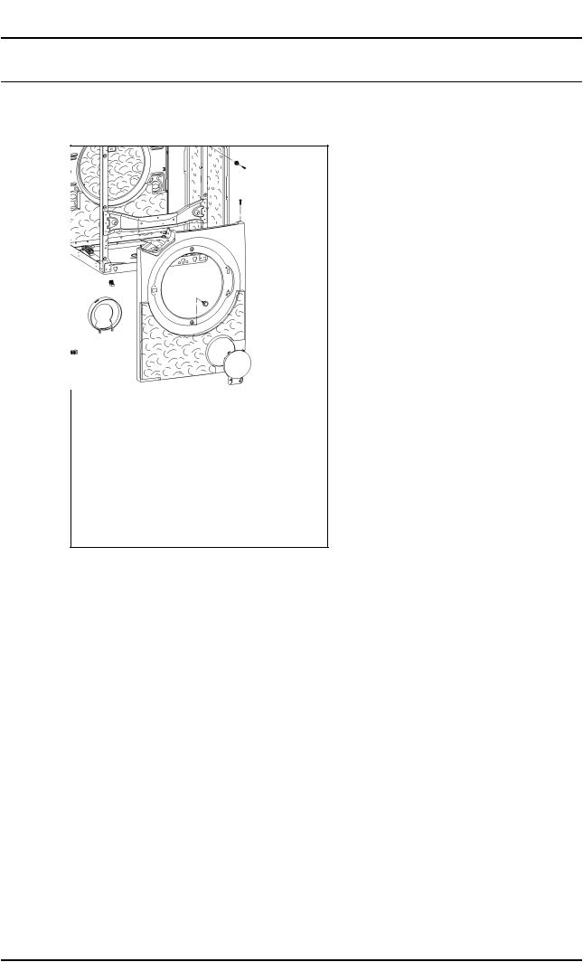
4.2Front panel – Remove
ARemove the appliance lid, refer to Lid – Remove, 010 4.1.
ARemove the control electronic (EW) and lower fascia panel, refer to Control electronic (EW) and Fascia support panel – Remove, 070 4.7.
x
Fig. 2
ARemove the door lock retaining screws.
ARemove the seal clamping ring.
ALoosen the door seal ring from the front panel.
ALoosen the attachment of the front panel above and below the fill hole.
ALoosen the attachment of the front panel at the detergent drawer and at the top on the right side.
ATilt the front panel forward at the top and lift it off.
AInstallation: Hook the manual release latch into the detergent drawer.
22.12.2006, US_am |
This information should not be duplicated or passed on without Miele approval. All rights reserved. |

|
Descriptive Technical Documentation |
010-6 |
DTD no. 11-4800 |
4.3Float switch (B8)
x
Danger!
Risk of electric shock when working on low-voltage components.
In the power electronic, there is no galvanic isolation from the power supply.
When working on a washer connected to the power supply, be aware of the risk of mains potential on low-voltage components.
This information should not be duplicated or passed on without Miele approval. All rights reserved. |
22.12.2006, US_am |
|
Descriptive Technical Documentation |
DTD no. 11-4800 |
020-1 |
020 Door, Magnet, Lock
22.12.2006, US_am |
This information should not be duplicated or passed on without Miele approval. All rights reserved. |

|
Descriptive Technical Documentation |
020-2 |
DTD no. 11-4800 |
1Technical Data
Special tools
Locking latch |
To run the appliance in the service department |
|
programming/service mode, with the front panel removed |
|
|
Porthole |
To run the appliance in the service department |
|
programming/service mode, with the front panel removed |
|
|
Table 1: Door, Magnet, Lock – Special tools
This information should not be duplicated or passed on without Miele approval. All rights reserved. |
22.12.2006, US_am |

|
Descriptive Technical Documentation |
DTD no. 11-4800 |
020-3 |
2Function
2.1Pull door lock (A2)
2.1.1Electromagnetic door lock
When locking the door, the locking latch dips into the lock and is pulled into the lock by the locking mechanism.
The power electronic (ELP) registers the locked state via a switch in the door lock (A2).
During operation, with the door closed, the door lock is electromagnetically bolted, refer to 020 2.1.2 Safety requirements.
As long as the door is not electromagnetically bolted, the door can be opened by simply pulling it.
Activating the emergency release cancels the electromagnetic lock, and the door can be opened.
x
Danger!
Opening the door by means of the emergency release may present danger of injury by a rotating drum, danger of scalding suds and flooding.
Note
Closing the door when the door lock is already locked causes damage to the door lock.
If the door lock is locked, with the door open, it has to be released manually, refer to Door lock (A2) – Open manually, 020 4.1.
2.1.2Safety requirements
After pressing the “Start” pad, the electromechanical door lock is only activated when the following safety requirements are met:
–Drum speed < 7 min-1, registered by RPM sensor (Tachogenerator),
–Water level < 80 mmWS, registered by analog pressure sensor (ADS),
–Suds temperature < 131°F (55°C), registered by suds temperature sensor (NTC resistor R30).
22.12.2006, US_am |
This information should not be duplicated or passed on without Miele approval. All rights reserved. |

|
Descriptive Technical Documentation |
020-4 |
DTD no. 11-4800 |
3Fault Repair
3.1Door lock (A2) does not lock
Symptom
The door latch hits the locking mechanism when pushing into the door lock (A2).
Cause
The locking mechanism is locked, with the door open.
Remedy
AOpen the door lock (A2) manually, refer to Door lock (A2) – Open manually, 020 4.1.
ACheck the function of the door lock (A2).
This information should not be duplicated or passed on without Miele approval. All rights reserved. |
22.12.2006, US_am |

|
Descriptive Technical Documentation |
DTD no. 11-4800 |
020-5 |
4Service
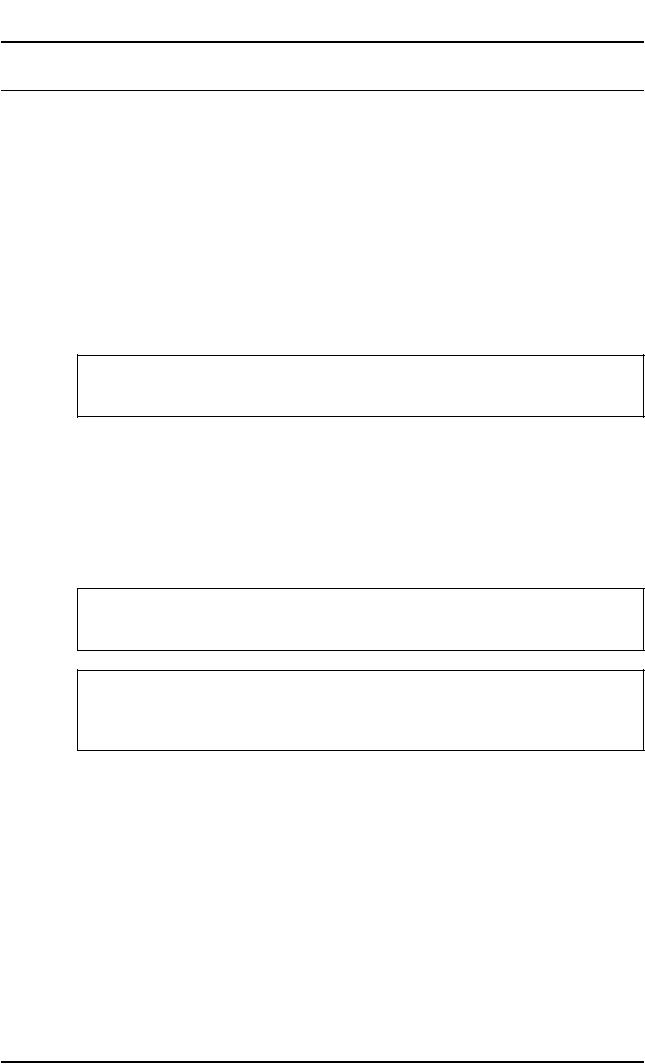
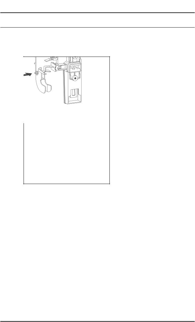
4.1Door lock (A2) – Open manually
x
Note
Manual opening is only required when the door locking mechanism is locked, with the door open.
This happens if the locking mechanism is interfered with, e.g. if an object is pushed into it.
In this situation, the locking latch cannot push into the lock and the door can't be closed.
Fig. 1
AWith the front panel in place, the door lock (A2) and the door seal fitted, press the door locking mechanism open.
22.12.2006, US_am |
This information should not be duplicated or passed on without Miele approval. All rights reserved. |
|
Descriptive Technical Documentation |
020-6 |
DTD no. 11-4800 |
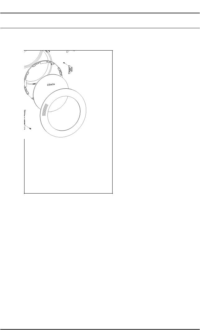
4.2Door lock (A2) – Remove
A Remove the front panel, refer to Front panel – Remove, 010 4.2.
x
Fig. 2
ALift the door lock (A2) and remove.
APull the plug off.
This information should not be duplicated or passed on without Miele approval. All rights reserved. |
22.12.2006, US_am |
|
Descriptive Technical Documentation |
DTD no. 11-4800 |
020-7 |
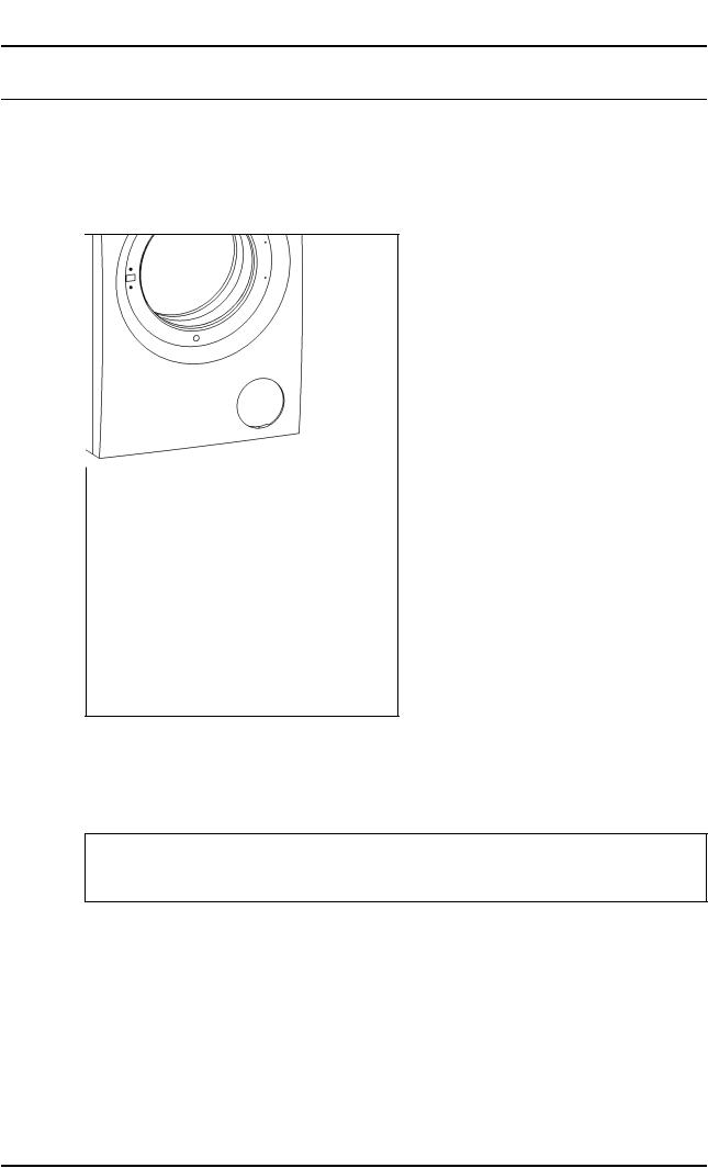
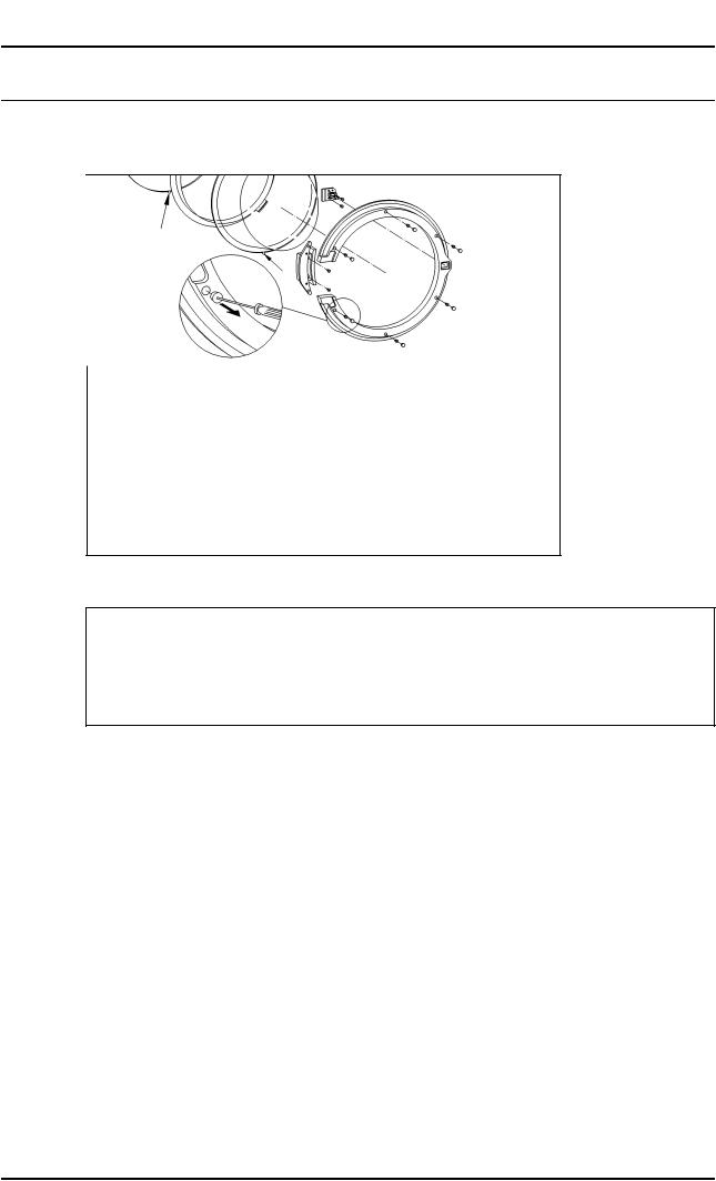
4.3Door porthole, door latch and hinge – Remove
x
Fig. 3
Note
The plugs in the door ring are destroyed during dismantling and have to be replaced when reassembling the door.
Do not damage the porthole ring when removing the plugs.
AUse a pointed tool to remove the plugs on the porthole ring.
ARemove the retaining screws.
22.12.2006, US_am |
This information should not be duplicated or passed on without Miele approval. All rights reserved. |

|
Descriptive Technical Documentation |
020-8 |
DTD no. 11-4800 |
This information should not be duplicated or passed on without Miele approval. All rights reserved. |
22.12.2006, US_am |
 Loading...