


 Loading...
User Guide
LRT214 / LRT224

Linksys |
Table of Contents |
Table of Contents
Introduction . . . . . . . . . . . . . . . . . . . . . . . . . . . . . . . . . . I |
|
|
|||||||||
Hardware Installation . . . . . . . . . . . . . . . . . . . . . . . . . . . .1 |
|
|
|||||||||
Ports |
|
|
|
|
|
|
|
|
1 |
|
|
LED Indicators |
|
|
|
|
|
|
|
|
2 |
|
|
Reset |
|
|
|
|
|
|
|
|
2 |
|
|
Placement Tips |
|
|
|
|
|
|
|
|
2 |
|
|
Wall Mounting Tips |
|
|
|
|
|
|
|
|
2 |
|
|
Getting Started with the Router Configuration . . . . . . . . . . . .3 |
|
|
|||||||||
System Status |
|
|
|
|
|
|
|
|
3 |
|
|
Setup . . . . . . . . . . . |
. |
|
|
|
|
. |
. |
. |
.7 . . . . . |
|
. |
Network . . . . . . . . . . . . . . . . . . . |
. |
. |
. . . . . . . . . . |
. . . |
.8 |
|
|
||||
Host Name and Domain Name |
|
|
|
|
|
|
|
8 |
|
|
|
IP Mode |
|
|
|
|
|
|
|
|
8 |
|
|
LAN Setting (Device IP address and subnets) |
|
|
|
|
|
8 |
|
|
|||
WAN Setting/ DMZ Setting (Internet connection & DMZ) |
|
|
9 |
|
|
||||||
Setting Password . . . . . . . . . . |
. |
. 14 . . |
|
. |
|||||||
Time . . . . . . . . . . |
. . |
|
|
|
|
. |
. |
14. . . . . . |
|
. |
|
DMZ Host . . . . . . . . . . . . . . . . . . |
. |
. |
. . . . . . . . . . |
. . |
. 15 |
|
|
||||
Port Forwarding and Port Triggering . |
. |
. |
. . . . . . . . . . |
. . |
. 16 |
|
|
||||
Port Range Forwarding |
|
|
|
|
|
|
|
|
16 |
|
|
Port Triggering |
|
|
|
|
|
|
|
|
17 |
|
|
Port Address Translation . . . . . . |
. |
. |
. |
. . |
. 18 |
|
|
||||
One-to-One NAT . . . . . . . . . . |
. |
. 19 . . |
|
. |
|||||||
Setting MAC Clone . . . . . . . . . |
. |
. |
. 20 . |
|
. |
||||||
Dynamic DNS . . . . . . . . . . . |
. 21 . . . |
. |
. |
||||||||
Advanced Routing . . . . . . . . . |
. |
. |
. 22 . |
|
. |
||||||
Dynamic Routing . . . . . . . . . . |
. |
. 22 . . |
|
. |
|||||||
Static Routing . . . . . . . . . . . |
. 22 . . . |
. |
. |
||||||||
|
|
|
|
|
|
|
|
|
|
|
|
|
|
Outgoing Mail Server . . . . . . . |
. |
. . |
. |
. 23 |
||||||||
|
|
IPv6 Transition . . . . . . . . . . . . . . |
. |
. . . |
. . . . . . . . . . . |
. 24 |
||||||||
|
|
DHCP . |
. . . . . . . . . |
. . |
|
|
|
|
|
|
|
|
. . |
. 25. . . . . . . . |
|
|
DHCP |
Setup . . . . . . . . . . . |
. |
|
|
|
|
|
25 . . . . . . |
||||
|
|
DHCP |
Status . . . . . . . . . . . |
. |
|
|
26 . . . . . . |
|||||||
|
|
Router Advertisement (IPv6) . . . . . . . . . . . . . . . . . . . . . 26 |
||||||||||||
|
|
IP & MAC Binding (for IPv4 Only) . |
. . |
. . |
. |
. |
|
. . |
. |
. . 27 |
||||
. |
|
DNS Local Database . . . . . . . |
. . |
. . |
. 28 . |
|||||||||
|
. |
|
|
|
|
|
|
|
|
|
|
|
|
|
|
|
System Management . . . . . . . . |
. |
. . |
. 30 . . |
|||||||||
|
|
Dual WAN (LRT224 Only) / Network Service Detection |
|
|
|
30 |
||||||||
|
|
Dual WAN |
|
|
|
|
|
|
|
|
|
|
30 |
|
|
|
Network Service Detection |
|
|
|
|
|
|
|
|
|
|
30 |
|
|
|
Protocol Binding (Only Dual-WAN Mode supports this function) |
31 |
|||||||||||
|
|
Bandwidth Management |
|
|
|
|
|
|
|
|
|
|
33 |
|
. |
. |
Session Control |
|
|
|
|
|
|
|
|
|
|
34 |
|
SNMP |
|
|
|
|
|
|
|
|
|
|
35 |
|||
|
|
SSL Certificate |
|
|
|
|
|
|
|
|
|
|
36 |
|
|
|
Port Management . . . . . . . . . . |
. |
. 37 . . . . |
||||||||||
|
|
Port Setup |
|
|
|
|
|
|
|
|
|
|
37 |
|
|
|
Port Status |
|
|
|
|
|
|
|
|
|
|
38 |
|
|
|
802.1Q |
|
|
|
|
|
|
|
|
|
. |
39 |
|
|
|
802..1Q LAN Status |
|
|
|
|
|
|
|
|
|
|
39 |
|
|
|
802..1Q LAN Configuration |
|
|
|
|
|
|
|
|
|
|
40 |
|
|
|
Firewall . . . . . . . . . . . . . . . . . . . . |
. |
. . . |
. . . . . . . . . . . |
. 41 |
||||||||
|
|
Firewall General Settings |
|
|
|
|
|
|
|
|
|
|
41 |
|
|
|
Access Rules |
|
|
|
|
|
|
|
|
|
|
42 |
|
|
|
Content Filter |
|
|
|
|
|
|
|
|
|
|
45 |
|
|
|
VPN . . |
. . . . . . . . . |
. |
|
|
|
|
. . . |
.47. . . . . . . |
||||
|
|
Summary |
|
|
|
|
|
|
|
|
|
|
47 |
|
|
|
Gateway to Gateway |
|
|
|
|
|
|
|
|
|
|
48 |
|
ii

Linksys |
Table of Contents |
Client to Gateway |
53 |
VPN Passthrough |
58 |
PPTP Server |
58 |
IP Address Range |
58 |
PPTP Server |
58 |
Connection List |
59 |
EasyLink VPN . . . . . . . . |
. . . . 60. |
Summary |
60 |
EasyLink VPN Server Status |
60 |
Inbound EasyLink VPN Status |
60 |
Outbound EasyLink VPN Status |
60 |
Inbound EasyLink VPN |
61 |
Add a New Account |
61 |
Outbound EasyLink VPN |
61 |
Edit Account |
61 |
OpenVPN . . . . . . . |
. . . . . .62. |
Summary |
62 |
OpenVPN Server Status |
62 |
OpenVPN Client Status |
62 |
OpenVPN Server |
62 |
Global Configure Settings |
63 |
OpenVPN Client |
65 |
Certificate Setting |
65 |
Log . . . . . . . . . . . . . . . .67.
System Log |
67 |
Syslog |
67 |
E-mail Alert |
67 |
Log Setting |
67 |
System Statistics |
68 |
Maintenance . . . . . . . . |
. . . . 70. |
Diagnostic |
70 |
DNS Name Lookup |
70 |
Ping |
70 |
Factory Default |
70 |
Firmware Upgrade |
71 |
Restart |
71 |
Backup and Restore |
71 |
Restore Startup Configuration |
71 |
Backup Configuration File |
71 |
Copy Configuration File |
71 |
Technical Support . . . . . . . . |
. . . . 72 . . . . |
. |
. |
. |
. |
. |
. |
. |
. |
. |
. |
. |
. |
. |
. . . . . . .
. |
. |
. |
. |
. |
. |
iii

Linksys
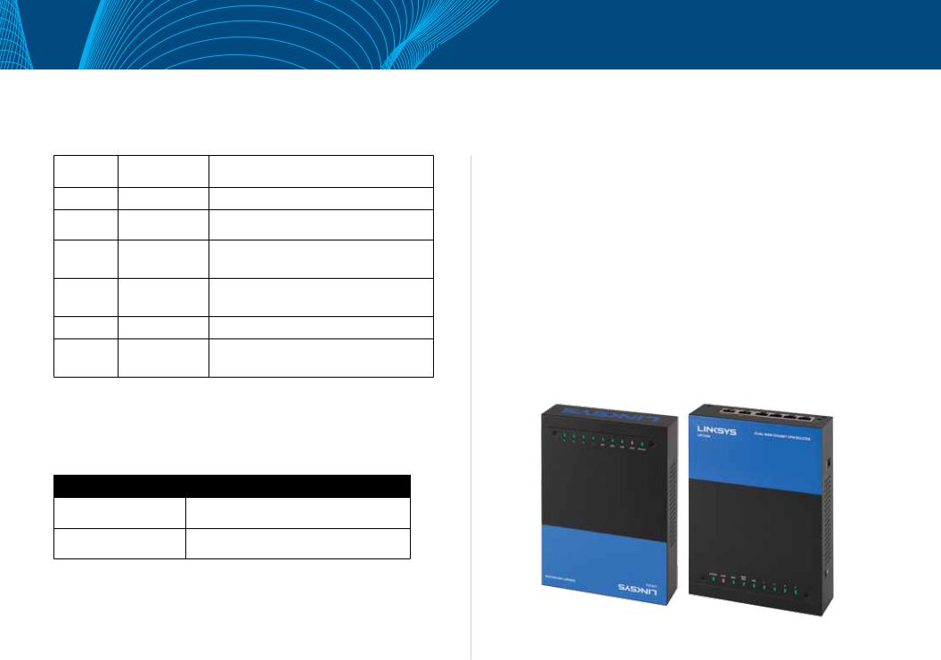
Introduction
LRT214/LRT224
Linksys’s VPN Routers for Small Business, LRT214 Gigabit VPN Router and LRT224 Dual WAN Gigabit VPN Router, support site-to-site VPN, which allows branch offices to connect with the central office, and client-to-site VPN, which allows employees to securely connect back to their offices while they are away.. The dual-WAN model supports WAN Failover, which allows a business to continue its network operation when one of its WAN connections to the Internet fails.. With dual-WAN load balancing, the dual-WAN model can aggregate the bandwidths of both WAN connections to achieve a higher Internet bandwidth than what a single WAN connection can provide..
Employees increasingly demand remote access to enterprise IT resources through their mobile devices such as smartphones and tablets.. LRT214/LRT224 support OpenVPN server, which allows OpenVPN clients running on employees’ laptops, smartphones, and tablets to connect to the offices using two-factor authentication. . Two-factor authentication typically requires pre-installed certificates as part of the authentication of an OpenVPN connection, in addition to username/password, for additional security..
The products come with an integrated firewall that supports URL filtering and access rules that allow administrators to further regulate the traffic within the business network based on the services (i.e. . . TCP/UDP ports) and source/ destination IP addresses..
LRT214/LRT224 routers support 802.1q,. which provides separation between resources in different SSIDs/VLANs. . This allows them to work with modern wireless access points that support multiple SSIDs. . . With inter-VLAN routing, the products allow specified traffic to traverse between VLANs.. The products support dual stack IPv4 and IPv6, as well as transition technologies such as 6to4..
Introduction
Like other Linksys routers, the products have an intuitive Web administrative interface that allows small business owners to deploy and manage the routers without professional IT staff onsite. . The operational health of the products can be monitored through system logs and email alerts. . Standard MIBs are supported, which allows the products to be monitored by a SNMP-based network management system..
I
Linksys
Hardware Installation
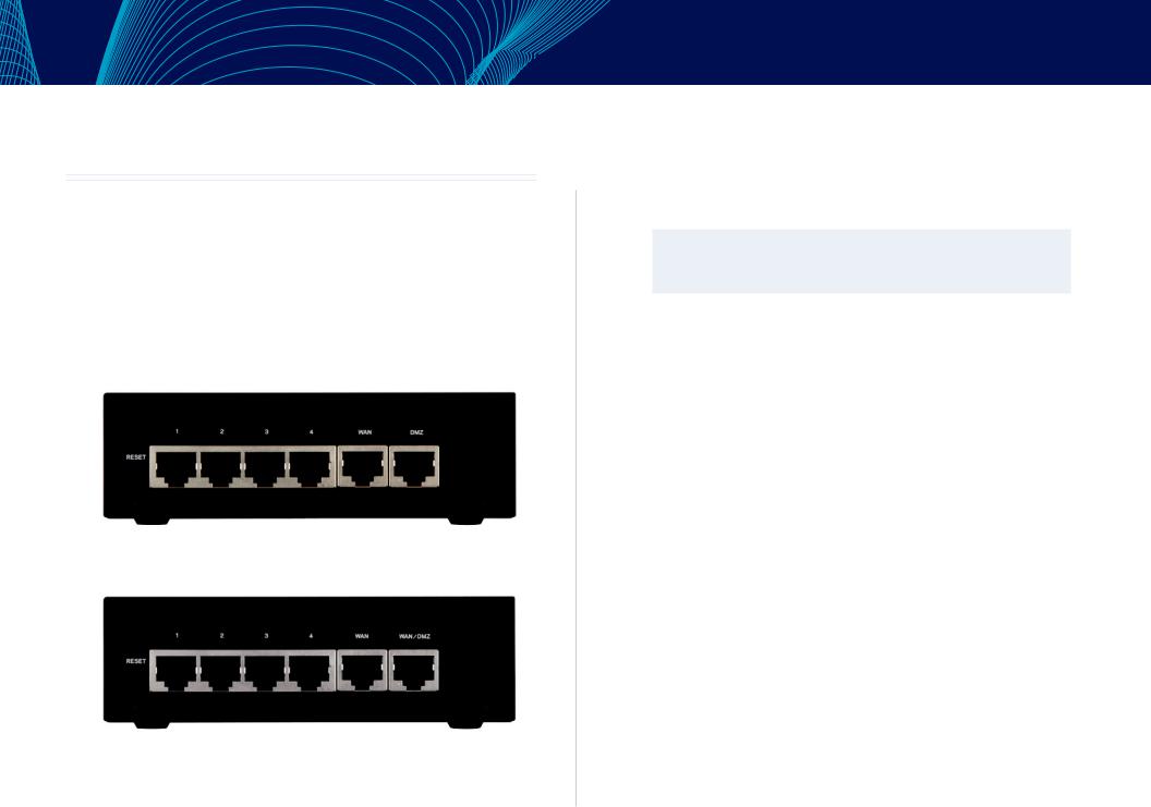
Ports
LRT214
In this chapter we are going to introduce hardware interface as well as physical installation.
LRT224
•• WAN: The WAN ports can be connected with DSL or cable modems, provided by your internet service provider (ISP).
Hardware Installation
•• DMZ: Use the DMZ (Demilitarized Zone) port to connect to a DMZ host, such as a Web server or mail server. Inbound traffic can access the DMZ host without exposing your intranet.
•• WAN/DMZ (LRT224):LRT224 Dual WAN Gigabit VPN Router comes with a port you can configure as a second WAN port or DMZ port based on your network requirements.
NOTE
Dual WAN settings, such as link failover or load balance, will be disabled when you configure the port as DMZ port.
LAN (1~4):Use the LAN ports to connect devices such as switching hubs, computers, printer servers, etc., to the local network or intranet.
1
Linksys
LED Indicators
LED Name |
Color |
Description |
|
System |
Green |
On: Power On |
|
Blinking: System booting up |
|||
|
|
||
DIAG |
|
On: System not ready |
|
Amber |
Off: System ready |
||
|
|
Blinking: System is on self-test |
|
|
|
Amber On: 10/100M link |
|
WAN |
Green/ Amber |
Amber Blinking: 10/100M activity |
|
Green On: Gigabit link |
|||
|
|
Green Blinking: Gigabit activity |
|
|
|
Amber On: 10/100M link |
|
WAN/DMZ |
Green/ Amber |
Amber Blinking: 10/100M activity |
|
Green On: Gigabit link |
|||
|
|
Green Blinking: Gigabit activity |
|
VPN |
Green |
On: Designated VPN tunnel up |
|
Off: Designated VPN tunnel down |
|||
|
|
||
1~4 |
|
Amber On: 10/100M link |
|
Green/ Amber |
Amber Blinking: 10/100M activity |
||
Ethernet |
Green On: Gigabit link |
||
|
|||
|
|
Green Blinking: Gigabit activity |
Reset
Action |
Description |
|
Press Reset Button For |
Warm start |
|
DIAG indicator: Diag LED flashing slowly |
||
5 Secs |
||
|
||
Press Reset Button |
Factory default |
|
DIAG indicator: Diag LED flashing quickly |
||
Longer than 10 Secs |
||
|
Hardware Installation
Placement Tips
•• Do not place anything on top of the router.. The router could be damaged by excessive weight..
•• Do not obstruct heat dissipation holes on the sides of the router..
•• Do not expose to direct sunlight or other heat source.. Keep area around router adequately ventilated..
•• Place the router on a flat surface..
Wall Mounting Tips
The router has two wall-mount slots on its bottom panel.. When mounting the router on the wall, please ensure that the heat dissipation holes are facing sideways as shown in the following picture for safety reasons.. Linksys is not responsible for damages incurred by insecure wall-mounting hardware..
2
Linksys |
Getting Started with the Router Configuration |
Getting Started with the Router Configuration
Follow the instructions to configure your router.
1.Be sure your computer is connected to a LAN port on the router and set to receive an automatic IP address from the DHCP server.
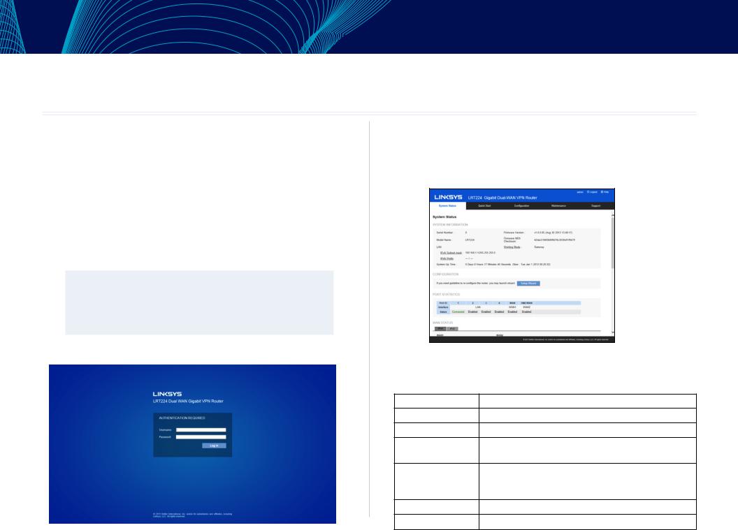
2.Open a Web browser and type 192.168.1.1 in the address bar.
3.On the login screen, type in default username: admin, and default password: admin. Click Log In.
4.Launch Setup Wizard – on the System Status or Quick Start tab – to complete configuration. Allow blocked content if asked.
5.The Configuration tab allows more control of your network based on your management needs.
NOTE:
Windows users can find the router IP address through the DOS prompt. Click on the Start button, enter “CMD” in the search field, and type “ipconfig” at the prompt. The IP address is the Default Gateway.
System Status
After logging in to the Web GUI, you will be directed to system status page, where you can glance how the router is configured. You can click on the System Status tab to view the current status of the router later on.
System Information
This section includes the following information:
Serial Number: |
Serial number of this router. |
Firmware Version: |
Current firmware version. |
Model Number: |
Model name of the router. |
MD5 Checksum: |
A value used for validation of the firmware installed on |
|
the router. |
LAN: |
Current LAN IP address of the router. |
IPv4/Subnet Mask |
|
IPv6/Prefix |
|
Working Mode: |
Current working mode as Gateway or Router mode. |
System Up Time: |
How long since the last restart (or power-up) of the router. |
3

Linksys
Configuration
You may click Setup Wizard button to launch wizard.
Port Statistics
Port ID: ID of physical port.
Interface: Type of the port: LAN, WAN or DMZ.
Status: Status of the port: Disabled, Enabled or Connected.
Clicking on a port’s status will launch a window with statistics on that port.
Getting Started with the Router Configuration
Type: |
10Base-T / 100 Base-TX / 1000 Base-TX. |
Interface: |
LAN/WAN/DMZ. |
Link Status: |
Up or down. |
Port Activity: |
Port Enabled, Port Disabled, or Port |
|
Connected. |
Priority: |
High or Normal. |
Speed Status: |
10Mbps, 100Mbps or 1000Mbps. |
Duplex Status : |
Half or Full. |
Auto Negotiation : |
On or Off. |
VLAN : |
VLAN ID. |
This table also gives you the counts for packets received and sent, packet bytes received and sent, and packet errors.
WAN Status
This section displays information for the WAN and DMZ interface.
NOTE:
You should enable Dual-Stack IP first to view IPv6 status. Please go to Configuration > Network.
IP Address: |
WAN IP address. |
Default Gateway: |
Default gateway IP address. |
DNS: |
IP address of the DNS server. |
Dynamic DNS: (IPv4 Only) |
Enabled or disabled. |
Release: |
If the WAN type is “Obtain an IP address |
|
automatically (DHCP),”this button will appear. |
|
Click Release to release the IP address. |
Renew: |
If the WAN type is “Obtain an IP address |
|
automatically (DHCP),” this button will |
|
appear. Click Renew to update the IP address. |
4
Linksys
Connect/ Disconnect: If the WAN type is PPPoE or PPTP, this button will appear. . Click Disconnect to cut the connection from ISP server.. Click Connect to re-dial to the server..
DMZ Status:
Note:
It is recommended to designate the configurable port on the LRT224 as a DMZ port.. Go to Device Configuration > Network and check the Enable DMZ box..
IP Address: IP address of DMZ port..
DMZ Host: Private IP of DMZ host..
Firewall Settings
This section displays the current firewall settings:
SPI (Stateful Packet Inspection): |
Default configuration is On.. |
DoS (Denial of Service): |
Default configuration is On.. |
Block WAN Request: |
Default configuration is On.. |
Remote Management: |
Default configuration is Off.. |
Access Rule: |
The number of access rules configured |
|
in the router.. |
VPN Settings
Tunnel(s) Used: Number of tunnels configured..
Tunnel(s) Available: Number of tunnels the router supports..
OpenVPN Status
Tunnel(s) Used: Number of OpenVPN tunnels configured..
Tunnel(s) Available: Number of OpenVPN tunnels the router supports..
Getting Started with the Router Configuration
Log Setting Status
This section displays the following information:
Syslog Server: Indicates whether Syslog server is activated..
Email Log: Indicates whether Email Log is activated..
5
Linksys |
Getting Started with the Router Configuration |
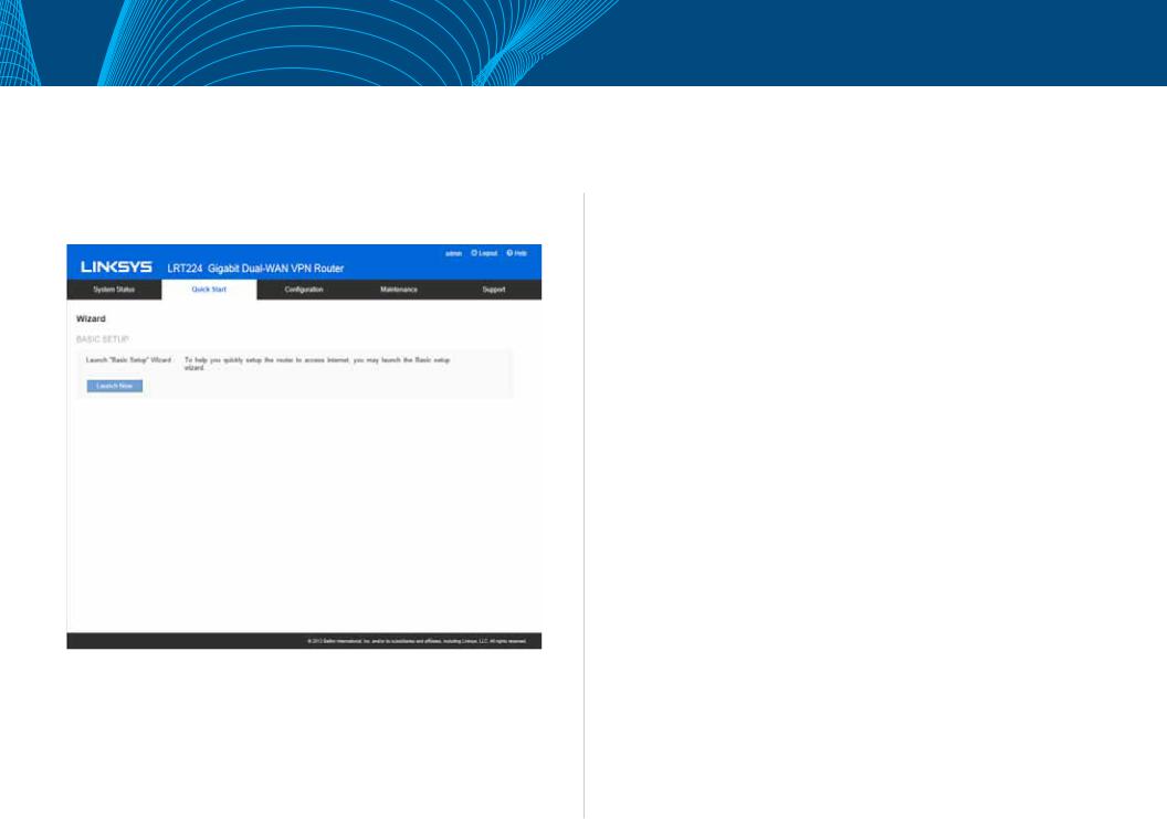
Quick Start (Setup Wizard)
Click the Quick Start tab to access Basic Setup Wizard.. The setup wizard will help you set up your network easily and finish basic network settings..
Basic Setup
Click Launch Now to run the Basic Setup Wizard.. Refer to the information from your ISP to enter the required settings for your connection..
You can configure Host and Domain, WAN setting, LAN setting, Time and Password here.. Click Finish button to leave the wizard..
6
Linksys |
Setup |
Setup
•Network
•Setting Password
•Time
•DMZ Host
•Forwarding
•Port AddressTranslation
•One-to-One NAT
•MAC Address Clone
•Dynamic DNS
•Advanced Routing
•IPv6Transition
7
Linksys
Network
Go to the Configuration > Setup > Network page to set up your LAN, WAN (Internet connections), and DMZ interface.
NOTE:
Remember to click Save before leaving the page. You can also click Cancel to undo the changes.
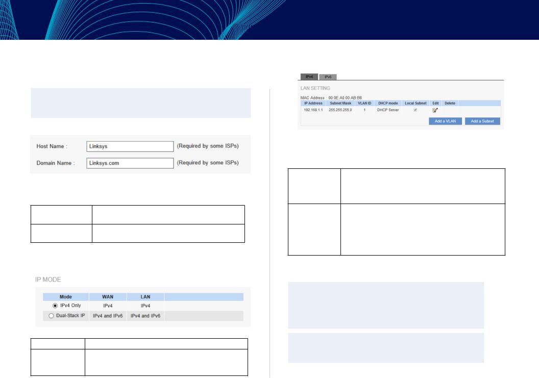
Host Name and Domain Name
Though this configuration is not necessary in most environments, some ISPs in some countries may require it.
Host Name: Keep the default setting or enter a host name specified by your ISP.
Domain Name: Keep the default setting or enter a domain name specified by your ISP.
IP Mode
Choose the type of addressing to use on your network:
IPv4 Only: Use only IPv4 addressing.
Dual-Stack IP: Use IPv4 and IPv6 addressing. After you enable this option, you can configure both IPv4 and IPv6 addresses for LAN, WAN, and DMZ settings on this page.
Setup
LAN Setting (Device IP address and subnets)
Changing the device IP address
Enter the following information:
For IPv4: Click the IPv4 tab, and then enter the Device IP Address and Subnet Mask.The default configuration is 192.168.1.1 and the default Subnet Mask is 255.255.255.0. It can be changed according to the actual network structure.
For IPv6: Users have to enable Dual-Stack IP in the IP mode section in advance to configure IPv6. Then click the IPv6 tab, and then enter the IPv6 Address and the Prefix Length. The default IP address is fc00::1, and the default prefix length is 7. It can be changed according to the actual network structure.
NOTE:
To configure global IPv6 prefixes for your LAN devices, go to the WAN Setting, click the IPv6 tab, and click Edit for the WAN interface. Then enter the LAN IPv6 Address. For more information, see WAN Setting (Internet connection).
NOTE:
Remember to click Save before leaving the page. You can also click Cancel to undo the changes.
8
Linksys
NOTE:
A pop-up confirmation message will appear to remind you to log in to the user Web GUI with the new device IP address. Click OK to confirm the change, or click Cancel to leave without applying the changes.
Multiple Subnet Setting (IPv4 only)
This function enables users to add IP segments that differ from the router network segment to the multi-net segment configuration. The Internet will then be directly accessible.
Add a VLAN: |
Click the button to add a new VLAN. The router |
|
supports up to 5 VLANs. In other words, you can |
|
add another 4 new VLANs. |
Add a Subnet for |
1. Click the button and a pop-up window will |
Outbound NATing: |
appear. |
|
2. Check “Add Local Subnet” or “Add Adjacent |
|
subnet (where you have another router to reach |
|
this subnet)” to identify the type of subnet. |
|
3. Enter a LAN IP address and a Subnet Mask. The |
|
IP address and subnet mask will appear in the list. |
|
Repeat this step as needed to add more subnets. |
|
4. You can also modify an existing subnet by clicking |
|
the edit icon. |
|
5. Click the trash can icon to delete the subnet. |
Setup
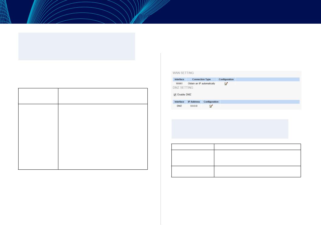
WAN Setting/ DMZ Setting (Internet connection & DMZ)
To set the WAN port to link to the Internet, refer to the configuration information provided by your ISP (Internet Service Provider). The WAN setting table shows WAN and DMZ ports of the router. You can configure the WAN/DMZ port for use as a DMZ.
WAN Setting
NOTE:
Remember to click Save before leaving the page. You can also click Cancel to undo the changes.
Interface: |
An indication of which port is connected. |
|
WAN |
Obtain an IP automatically, Static IP, PPPoE (Point- |
|
ConnectionType: |
to-Point Protocol over Ethernet), PPTP (Point-to- |
|
Point Tunneling Protocol) and Transparent Bridge. |
||
|
||
Config.: |
A modification in an advanced configuration. Click |
|
|
Edit to enter the advanced configuration page. |
9

Linksys
Obtain an IP Automatically:
This mode is often used in the connection mode to obtain an automatic DHCP IP. This is the device system default connection mode. It is a connection mode in which DHCP clients obtain an IP address automatically. To use a different connection mode, refer to the following instructions for selection of appropriate configurations. Users can also set up their own DNS IP address. Check the options and input the user-defined DNS IP addresses.
Use the following DNS |
Select a user-defined DNS server IP address. |
Server Addresses: |
|
DNS Server: |
Input the DNS IP address set by ISP. At least |
|
one IP group should be input. The maximum |
|
number of acceptable groups is two. |
MTU(MaximumTransmission |
Choose Auto or Manual. Default is Auto. The |
Unit) |
default value is 1500. Different value could be |
|
set in different network environment (e.g., ADSL |
|
PPPoE MTU: 1492). |
Setup
Static IP:
If an ISP issues a static IP (such as one IP or eight IP addresses, etc.), please select this connection mode and follow the steps below to input the IP numbers issued by an ISP into the relevant boxes.
Specify WAN IP address: |
Input the available static IP address issued by |
|
|
your ISP. |
|
Subnet Mask: |
Input the subnet mask of the static IP address |
|
|
issued by ISP, such as: |
|
|
Issued eight static IP addresses: 255.255.255.248 |
|
|
Issued 16 static IP addresses: 255.255.255.240 |
|
Default Gateway: |
Input the default gateway issued by ISP. For |
|
|
ADSL users, it is usually an ATU-R IP address. |
|
|
Optical fiber users should input the optical fiber |
|
|
switching IP. |
|
DNS Server: |
Input the DNS IP address issued by your ISP. |
|
|
At least one IP group should be input. The |
|
|
maximum number of acceptable groups is two. |
|
MTU |
Choose “Auto” or “Manual.” Default is “Auto.” The |
|
(Maximum Transmission |
default value is 1500. Different value could be |
|
Unit): |
set in different network environment (e.g., ADSL |
|
PPPoE MTU: 1492). |
||
|
10

Linksys
PPPoE:
This option is for an ADSL virtual dial-up connection (suitable for ADSL PPPoE).
User Name: |
Input the user name issued by your ISP. |
Password: |
Input the password issued by your ISP. |
Connect on Demand: |
This function enables the auto-dialing function |
|
in a PPPoE dial connection. When the client port |
|
attempts to connect with the Internet, the device |
|
will automatically make a dial connection. If the |
|
line has been idle for a period of time, the system |
|
will break the connection automatically. (The |
|
default time for automatic disconnection from no |
|
packet transmissions is five minutes). |
Keep Alive: |
This function enables the PPPoE dial connection to |
|
keep connected, and to automatically redial if the |
|
line is disconnected. It also enables a user to set |
|
up a time for redialing. The default is 30 seconds. |
Use the following DNS |
Select a user-defined DNS server IP address. |
Server Addresses: |
|
DNS Server: |
Input the DNS IP address set by ISP. At least one IP |
|
group should be input. The maximum number of |
|
acceptable groups is two. |
MTU (Maximum |
Choose “Auto” or “Manual”. Default is “Auto.” The |
Transmission Unit) |
default value is 1500. Different value could be |
|
set in different network environment (e.g., ADSL |
|
PPPoE MTU: 1492). |
|
Setup |
PPTP: |
|
Specify WAN |
The IP address to be configured could be one |
IP Address: |
issued by your ISP. (The IP address is usually |
|
provided by the ISP when the PC is installed. |
|
Contact your ISP for relevant information). |
Subnet Mask: |
Input the subnet mask of the static IP address |
|
issued by your ISP, such as: |
|
Issued eight static IP addresses: 255.255.255.248 |
|
Issued 16 static IP addresses: 255.255.255.240 |
Default Gateway: |
Input the default gateway of the static IP address |
|
issued by your ISP. For ADSL users, it is usually an |
|
ATU-R IP address. |
User Name: |
Input the user name issued by your ISP. |
Password: |
Input the password issued by your ISP. |
Connect on Demand: |
This function enables the auto-dialing function |
|
to be used for a PPTP dial connection. When the |
|
client port attempts to connect with the Internet, |
|
the device will automatically connect with the |
|
default ISP auto dial connection. When the |
|
network has been idle for a period of time, the |
|
system will break the connection automatically. |
|
(The default time for automatic break off when no |
|
packets have been transmitted is five minutes). |
Keep Alive: |
This function enables the PPTP dial connection |
|
to redial automatically when the connection has |
|
been disconnected. Users can set up the redialing |
|
time. The default is 30 seconds. |
MTU: |
Choose “Auto” or “Manual”. Default is “Auto.” The |
|
default value is 1500. Different value could be |
|
set in different network environment (e.g., ADSL |
|
PPPoE MTU: 1492). |
11

Linksys
L2TP
Specify WAN IP Address |
Configure a static IP address. The IP address |
|
could be one issued by an L2TP server. |
Subnet Mask |
Input the subnet mask of the static IP address. |
Default Gateway |
Input the IP address of the L2TP server. |
Username |
Input the username of the L2TP client. |
Password |
Input the password of the L2TP client. |
Connect on Demand |
Enables auto-dialing for a dial connection. When |
|
the client port tries to connect to the Internet, |
|
the device will automatically connect with the |
|
L2TPserver. When the network has been idle |
|
for a period of time, the system will break the |
|
connection automatically. (The default time for |
|
automatic connection break is five minutes). |
Keep Alive |
Enables the dial connection to redial |
|
automatically when disconnected. Set the |
|
redialing time (default is 30 seconds). |
MTU |
Choose Auto or Manual. Default setting is Auto. |
|
The default manual setting value is 1500 bytes. A |
|
different value could be set in a different network |
|
environment (e.g., ADSL PPPoE MTU: 1492). |
Setup
Transparent Bridge:
The feature will come in handy in when a company wants to add a firewall or dual-WAN device without changing the IP addresses of the computers in its intranet. This function will enable users to integrate existing networks without changing the original structure. Select the Transparent Bridge mode for the WAN connection mode. In this way, users will be able to connect normally to the Internet while keeping the original IP addresses in the intranet.
If there are two WANs configured, users still can select Transparent Bridge mode for WAN connection mode, and load balancing will still function as usual.
SpecifyWANIPAddress: |
Input one of the static IP addresses issued by ISP. |
|
SubnetMask: |
Input the subnet mask of the static IP addresses |
|
|
issued by your ISP: 255.255.255.248 if your ISP |
|
|
issues six usable addresses, and 255.255.255.240 if |
|
|
your ISP issues 14 useable addresses. |
|
DefaultGateway: |
Input the default gateway of the static IP address |
|
|
issued by your ISP. For ADSL users, it is usually an |
|
|
ATU-R IP address. |
|
DNSServer: |
Input the DNS IP address set by your ISP. At least |
|
|
one IP group should be input. The maximum |
|
|
acceptable is two IP groups. |
|
InternalLANIPRange: |
Input the available IP range issued by your ISP. |
|
|
If your ISP issued two discontinuous IP address |
|
|
ranges, users can input them into Internal LAN IP |
|
|
Range 1 and Internal LAN IP Range 2, respectively. |
|
MTU |
Choose “Auto” or “Manual”. Default is “Auto.” The |
|
(MaximumTransmission |
default value is 1500. Different value could be |
|
Unit): |
set in different network environment (e.g., ADSL |
|
PPPoE MTU: 1492). |
||
|
12
Linksys
DMZ Setting
For some network environments, an independent configurable DMZ port may be required to set up externally connected servers such as WEB and Mail servers. Therefore, the device supports a set of independent configurable DMZ ports for users to set up connections for servers with real IP addresses. The DMZ ports act as bridges between the Internet and LANs.
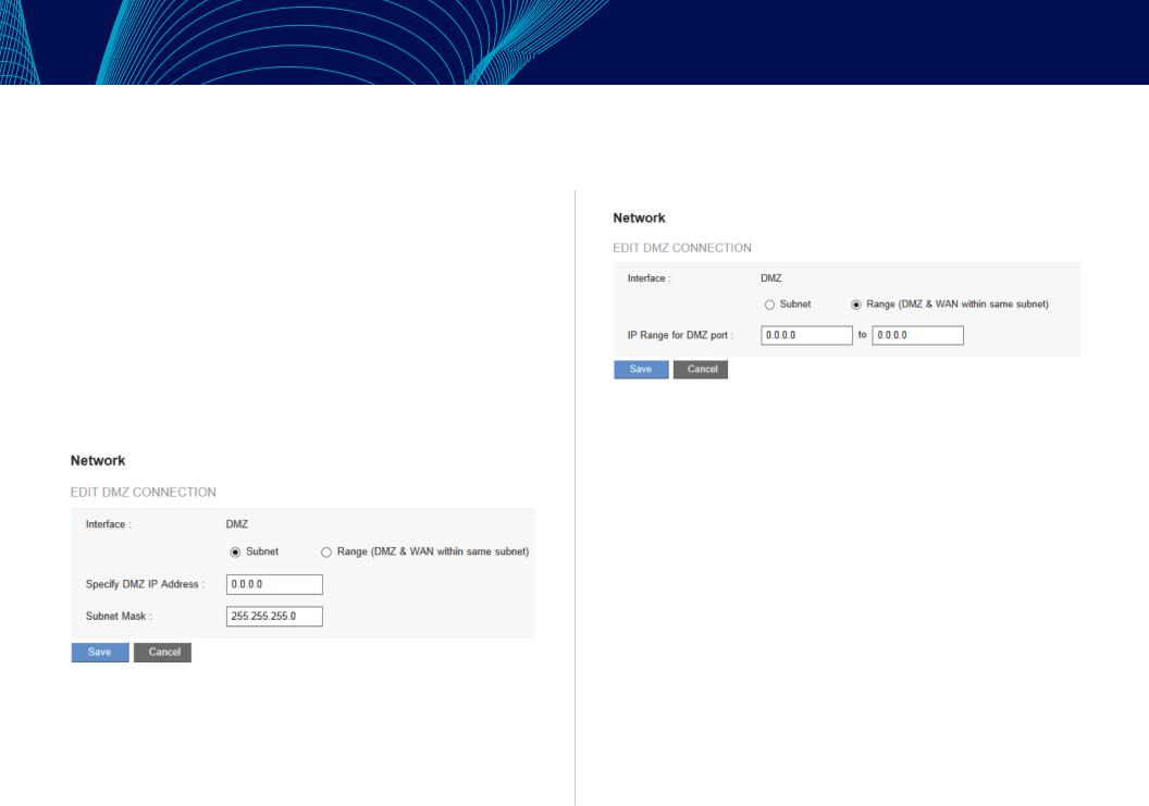
Check Enable DMZ box and click the edit icon to configure DMZ port. The DMZ configuration can be classified by subnet and range.
Subnet:
If the DMZ and WAN are located in different subnets:
If the ISP issued useable public IP addresses: 220.243.230.1-14 with Mask 255.255.255.240, users have to separate the 14 IP addresses into two groups: 220.243.230.1-6 with Mask 255.255.255.248, and 220.243.230.9-14 with Mask 255.255.255.248 and then set the device and the gateway in the same group with the other group in the DMZ.
Setup
Range:
If the DMZ and WAN are within same subnet:
IP Range: Input the IP range located at the DMZ port.
13
Linksys
Setting Password
Use the Configuration > Setup > Password page to change the administrator username and password. It is strongly recommended to change the default username and password (admin/admin).
CAUTIONIf the password is forgotten, reset the router to factory default settings. All the configurations of the router will disappear.
NOTE:
Remember to click Save before leaving the page. You can also click Cancel to leave without any change.
NOTE:
If you want to enable remote access on the Firewall > General setting, changing your password is necessary.
Old Password: |
Enter the old password. The default |
|
|
password is admin. |
|
New Username: |
Enter a new username. To keep the |
|
|
existing username, leave this field blank. |
|
Confirm New Username: |
Re-enter the new username. |
|
New Password: |
Enter a new password for the router. |
|
|
Alphanumeric characters and symbols |
|
|
are allowed, but no spaces. |
|
Confirm New Password: |
Re-enter the new password. |
|
Minimum |
Check the box to enable box if you want |
|
Password Complexity: |
to enforce password complexity and |
|
enable the Password Strength Meter. |
||
|
||
|
This option is enabled by default and is |
|
|
recommended. |
NOTE:
When Minimum Password Complexity is enabled, the password must meet the requirements listed below.
Setup
•At least 8 characters.
•The password cannot be the same as Username.
•The password cannot be the same as the current password
•Must contain characters from at least 3 of the following 4 categories: uppercase letters, lowercase letters, numbers, and special characters available on a standard keyboard.
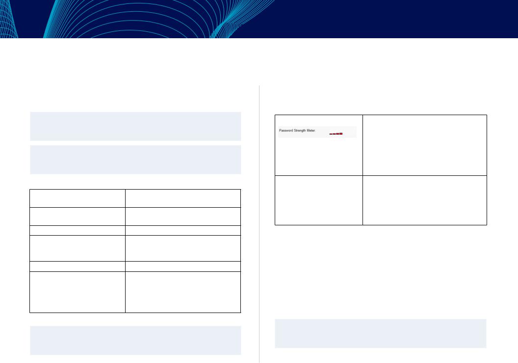
Password Strength Meter: |
When enabling Minimum Password |
|
|
Complexity, the Password Strength Meter |
|
|
appears and indicates the password |
|
|
strength. |
|
|
Red means you have to reset the password. |
|
|
Yellow means the password is acceptable. |
|
|
Green means the password is strong. |
|
Password |
Choose Disable to make the password |
|
Aging Enforcement: |
permanent. Choose Change the password |
|
after if you want the password to expire |
||
|
||
|
after the specified period. Check Change |
|
|
the password after and input the specified |
|
|
number of Days. |
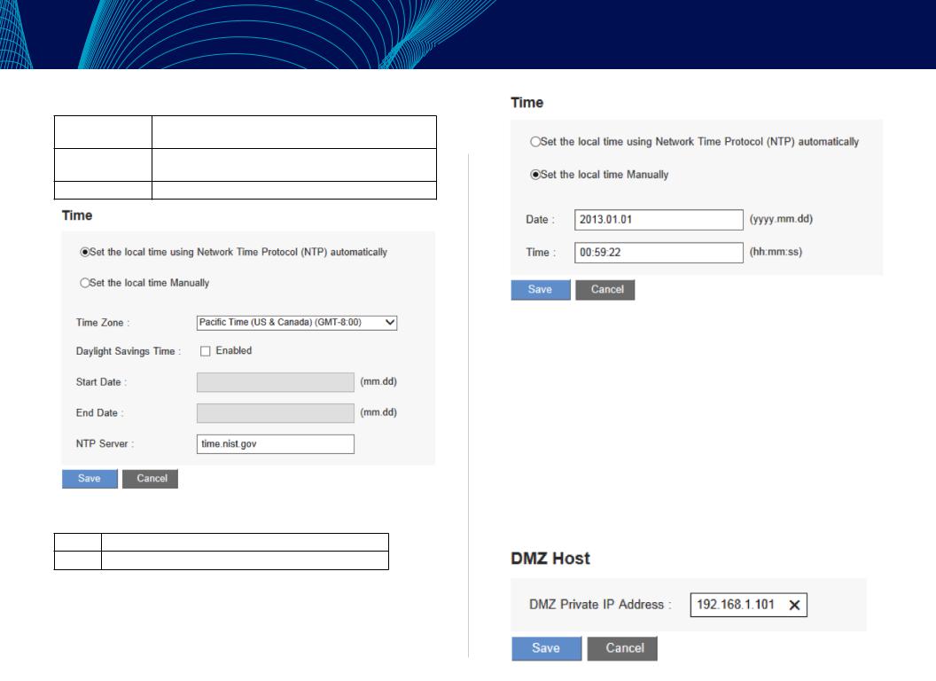
Time
Go to Configuration > Setup > Time page to configure the system time. The exact time of event occurrences will be recorded in the System Log, as will the time of closing or opening of access for Internet resources. You can select the
NTP Server synchronization function or set up a time manually.
NOTE:
Remember to click Save before leaving the page. You can also click Cancel to undo the changes.
14
Linksys
Set the local time using NetworkTime Protocol (NTP) automatically:
Time Zone |
Select your location from the pull-down time zone list to |
|
show correct local time. |
Daylight Saving |
If there is Daylight Saving Time in your area, click |
|
Enabled and enter start date and end day of the period. |
NTP Server |
Input NTP server IP address. |
Set the local time manually:
Date: |
Input date as yyyy.mm.dd, i.e., 2013.9.30. |
Time: |
Input current time as hh:mm:ss, i.e., 08:50:00. |
Setup
DMZ Host
When the NAT mode is activated, users may need to use applications that do not support virtual IP addresses, such as network games or video conferencing. We recommend that users map the device actual WAN IP
addresses directly to the intranet virtual IP addresses. Setting up a DMZ host will allow one host in the LAN to be exposed to the Internet to use services such as Internet gaming and video conferencing. Access to the DMZ host from the Internet can be restricted by using firewall access rules. Use the Configuration > Setup > DMZ Host page.
Enter the LAN IP address of the server that you want to use as a DMZ host.
15
Linksys
NOTE:
Remember to click Save before leaving the page. You can also click Cancel to undo the changes.
Port Forwarding and Port Triggering
You can set up a port forwarding virtual host to allow public access to servers connected to the LAN ports. Port Forwarding opens a specified port or a port range for a service, such as FTP, WWW, and mail, etc. Port Triggering opens a port range for services that use alternate ports to communicate between the server and LAN host. Use the Configuration > Setup > Forwarding page to configure.
•Port Range Forwarding
•PortTriggering
NOTE Remember to click Save before leaving the page. You can also click Cancel to undo the changes.
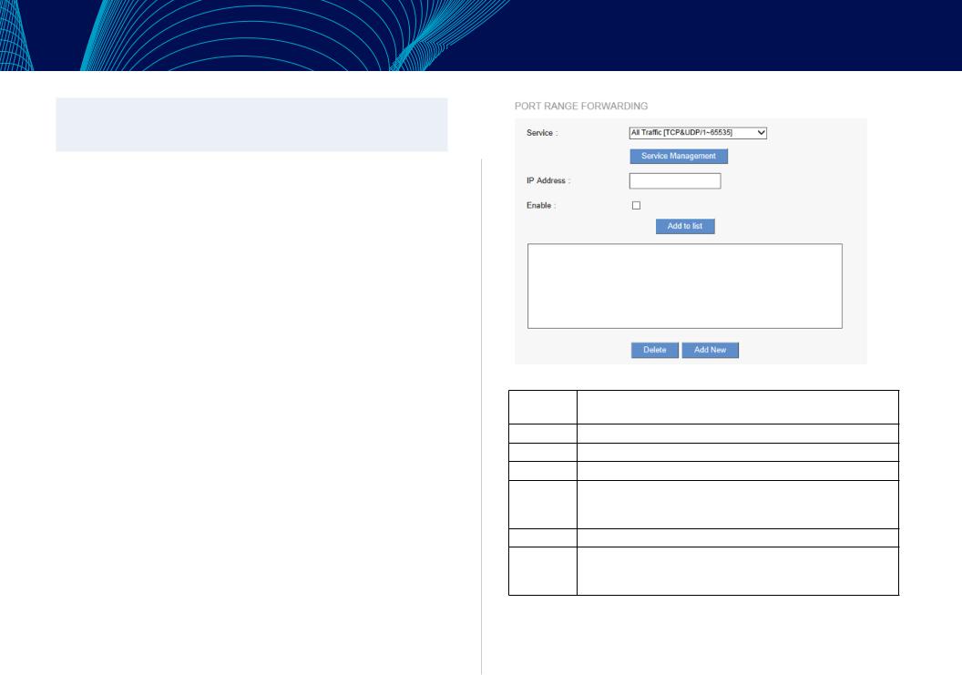
Port Range Forwarding
Port forwarding can be used to set up public services on your network. When users from the Internet make certain requests to your network, the router can forward those requests to computers that are equipped to handle the requests. If, for example, you set the port number 80 (HTTP) to be forwarded to IP address 192.168.1.2, then all HTTP requests from outside users will be forwarded to 192.168.1.2.
To set up other services input the server TCP or UDP port number and the virtual host IP addresses.
Setup
Service |
Select the service. You can also add a new service from |
|
Service Management. |
IP Address |
Input the LAN IP address of the virtual host. |
Interface |
Select the WAN port. (Dual WAN router only) |
Add to list |
Click the button to add a new entry. |
Update |
Select the entry that you want to modify. Change the setting |
|
and then click Update. Clicking Add New deselects the entry |
|
and clears the text fields. |
Delete |
Click the entry and then click Delete. |
View |
To view the entry table, choose Port Range Forwarding or |
|
Port Triggering.Click Refresh to renew the display. Click Close |
|
to return to configuring page. |
16
Linksys
Adding a service
To add a new service item or to edit an existing service, click Service Management. If the web browser displays a warning about the pop-up window, click to allow the blocked content.
In the Service Management window, add or edit entries as needed. After setting a rule, be sure to click OK to save your settings, or click Cancel to undo them. To add a service to the list, enter the following information, and click Add to List. You can have up to 30 services in the list.
•Service Name: Give a name to the service.
•Protocol: Choose the required protocol: TCP, UDP or IPv6.
•Port Range: Enter a range.
Setup
•To add another new service: Enter the information, and then click Add to list.
•To edit a service you created: Select the service in the list and then click Update to make the changes. If you do not need to make changes, click Add New to deselect the service and clear the text fields.
•To delete a service from the list: Click Delete to delete an existing service.
Port Triggering
Some Internet applications use alternate ports to communicate between the server and LAN host. Port Triggering opens a port range for those services. The device will forward the incoming packets to the assigned LAN host.
17
Linksys
Application Name: |
Enter the name of the application. |
Trigger Port Range: |
Input the starting and ending port numbers of |
|
the trigger port range. |
Incoming Port Range: |
Input the starting and ending port numbers of |
|
the incoming port range. |
Add to list: |
Click the button to add a new entry. Up to 30 |
|
applications are supported. |
Update: |
Select the entry that you want to modify. |
|
Change the setting and click Update. Clicking |
|
Add New deselects the entry and clears the |
|
text fields. |
Delete: |
Click the entry and then click Delete . |
View: |
To view the entry table, choose Port Range |
|
Forwarding or PortTriggering. Click Refresh |
|
to renew the display. Click Close to return to |
|
configuring page. |
Setup
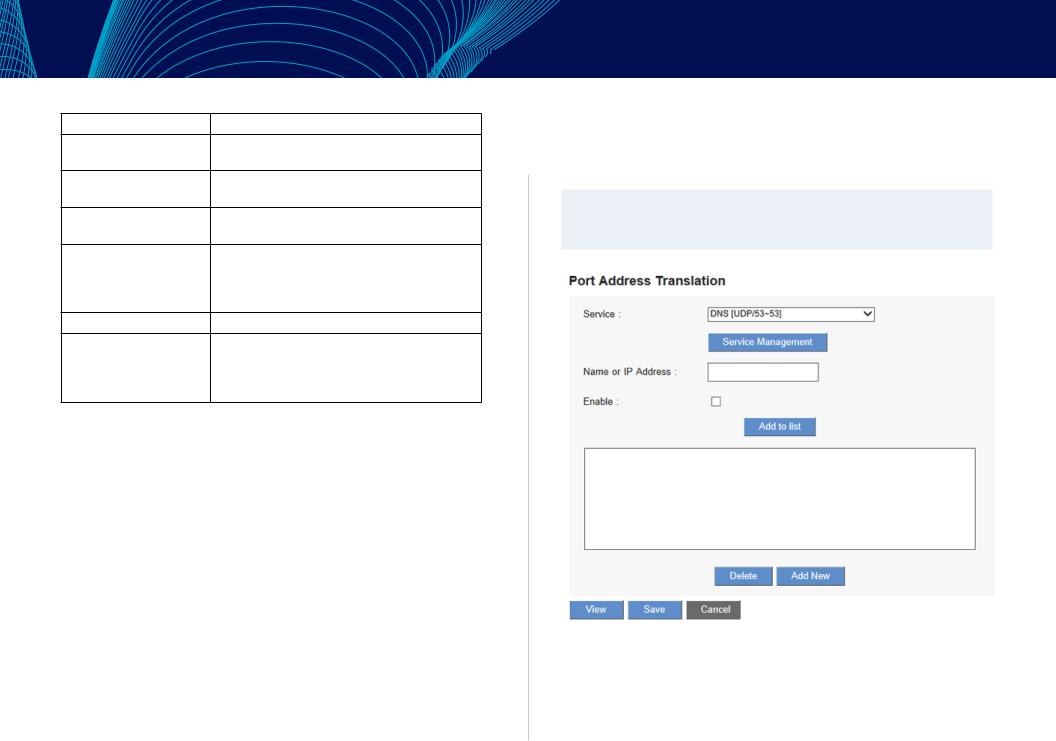
Port Address Translation
Use the Setup > Port Address Translation. This feature allows Windows to automatically configure the router to open and close ports for Internet applications such as gaming and videoconferencing.
NOTE:
Remember to click Save before leaving the page. You can also click Cancel to undo the changes.
18

Linksys
Service |
Select the service. You can also add a new service |
|
from Service Management. |
Name or IP Address |
Input the Intranet virtual IP address or host name. |
Enable |
Activate this function. |
Service Management |
Add or remove service ports from the |
|
management list. |
Add to List |
Click the button to add a new entry. |
Update |
Select the entry that you want to modify. Change |
|
the setting and click Update. Clicking Add New |
|
deselects the entry and clears the text fields. |
Delete |
Click the entry and then click Delete. |
View |
To view the entry table, click Refresh to update the |
|
display. Click Close to return to configuring page. |
Adding a service
To add a new service item or to edit an existing service, click Service Management. If the web browser displays a warning about the pop-up window, click to allow the blocked content.
In the Service Management window, add or edit entries as needed. After setting a rule, be sure to click OK to save your settings or click Cancel to undo them. To add a service to the list: Enter
•Service Name: Give a name to the service.
•Protocol: Choose the required protocol: TCP, UDP or IPv6.
•Port Range: Enter the port range.
•To add another new service: enter the information, and click Add to list.
•To edit a service you created: , select the service in the list and click Update to make the changes. If you do not need to make changes, click Add New to deselect the service and clear the text fields.
•To delete a service from the list, click Delete.
Setup
One-to-One NAT
If your ISP issued more than one actual IP (such as eight ADSL static IP addresses or more), you can map the remaining real IP addresses to the intranet devices with virtual IP addresses.
You can also map a private IP address range to a public IP address range of equal length (for example, five private addresses and five public addresses). The first virtual address will be mapped to the first external address.
Use the Configuration > Setup > One-to-One NAT page to enable One-to-One NAT (Network Address Translation).
NOTE Remember to click Save to save your settings before leaving the page. You can also click Cancel to leave without any change.
19
Linksys
Enabled One to One NAT: |
Check to enable the One-to-One NAT function. |
Private Range Begin: |
Input the Private IP address for the Intranet |
|
One-to-One NAT function. |
Public Range Begin: |
Input the Public IP address for the Internet |
|
One-to-One NAT function. |
Range Length: |
Input the numbers of final IP addresses of |
|
actual Internet IP addresses. (Please do not |
|
include IP addresses in use by WAN ports.) |
Add to List: |
Add this configuration to the One-to-One NAT |
|
list. |
Update: |
Select the entry that you want to modify. |
|
Change the setting and click Update. Clicking |
|
Add New will deselect the entry and clear the |
|
text fields. |
Delete: |
Click the entry and then click Delete. |
Setup
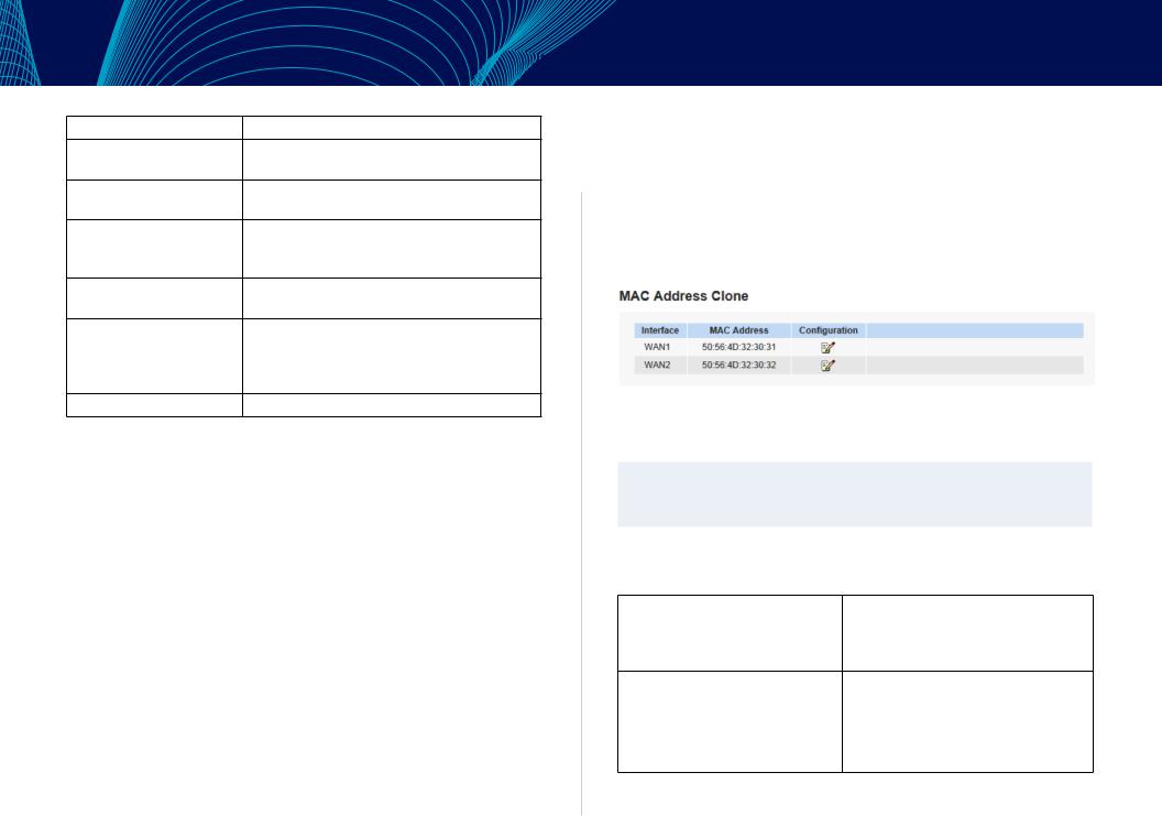
Setting MAC Clone
Some ISPs ask for a fixed MAC address (network card physical address) for distributing IP addresses. Users can input the network card physical address (MAC address: 00-xx-xx-xx-xx-xx) here. The Linksys LRT series router will adopt this MAC address registered to your ISP. Use the Configuration > Setup > MAC Address Clone page
Click Edit to get into configuring page.
MAC Clone Settings
NOTE:
Remember to click Save before leaving the page. You can also click Cancel to leave without any change.
To clone a MAC address, enter the following settings. Select the interface you want to configure if the router supports dual WAN ports.
User Defined WAN MAC Address: Check this item to manually clone a MAC address. Enter the 12 digits of the MAC address that you registered with your ISP.
MAC Address from this PC: |
Check this item to clone the MAC |
|
address of the device you are currently |
|
using. |
|
The MAC address of your PC is |
|
displayed automatically. |
20
Loading...