


 WARNING
This device is for use ONLY on LiftMaster Commercial Door Operators. Use on other than recommended equipment voids warranty, and may cause property damage or SERIOUS personal INJURY. Read and follow ALL instructions.
Have door in full open or closed position and DISCONNECT power to the operator BEFORE installing the Commercial Protector System®.
Commercial Protector System®
OWNER’S MANUAL
For use with Models CPS, CPSIII-01 and CPS-L
|
Part # |
Description |
QTY |
|
|
|
|
|
|
12B483 |
“C” Wrap Brackets |
2 |
||
|
|
|
|
|
|
12B485 |
Slotted Bracket |
2 |
|
|
|
|
|
|
|
12B484 |
Square Hole Bracket |
2 |
|
|
|
|
|
|
|
41A4116 |
Safety Sensor Hardware |
1 |
|
|
|
|
|
|
|
41K4654 |
Safety Sensor Kit |
1 |
|
|
|
(receiving and sending eyes) |
|
|
|
|
|
|
|
|
1A6078 |
Option Board (CPSIII ONLY) |
1 |
|
|
|
|
|
|
|
41K4629 |
Commercial Protector Interface (CPS ONLY) |
1 |
|
|
|
|
|
|
The brackets must be securely fastened to a solid surface such as the wall framing. If installing in masonry construction, add a piece of wood at each location to avoid drilling extra holes in masonry if repositioning is necessary.
The invisible light beam path must be unobstructed. No part of the garage door (or door tracks, springs, hinges, rollers or other hardware) may interrupt the beam while the door is closing. If it does, use a piece of wood to build out each sensor mounting location to the minimum depth required for light beam clearance.
|
— Right Side of Garage — |
Invisible Light |
|
Beam Protection |
Safety Reversing |
Area |
Sensor |
procedures are the same for all door types).
1
I N S T A L L AT I O N F O R L I F T M A S T E R C O M M E R C I A L O P E R AT O R S
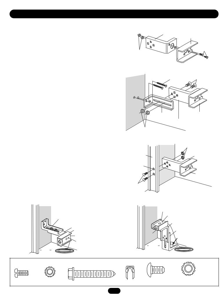
INSTALLING THE BRACKETS
Figures 1, 2 and 3 show recommended assembly of the bracket(s) and “C” wrap based on the wall installation of the sensors on each side of the door as shown on page 1 or on the door tracks themselves.
Figures 4 and 5 are variations which may fit your installation requirements better. Make sure the wraps and brackets are aligned so the sensors will face each other across the door.
WALL OR DOOR TRACK INSTALLATION
•Fasten the “C” wraps to the mounting brackets having square holes, using hardware shown in Figure 1.
WALL INSTALLATION
•Connect each assembly to a slotted bracket, using the hardware shown (Figure 2).
•Finger tighten the lock nuts.
•Use bracket mounting holes as a template to locate and drill
(2) 3/16" diameter pilot holes on the wall at each side of the door, no higher than 6" above the floor.
•Attach brackets to wall with lag screws as shown in Figure 2.
•Adjust right and left side bracket assemblies to the same distance out from mounting surface. Make sure all door hardware obstructions are cleared. Tighten the nuts securely.
DOOR TRACK INSTALLATION
•Discard slotted bracket. Drill 3/8" holes in each track and fasten securely with hardware as shown in Figure 3.
Figure 1 WALL or DOOR Track Installation
Mounting Bracket
With Square Holes
“C” Wrap
#10-32x3/8"
Screws
#10-32 Lock Nuts
Figure 2 WALL Installation
1/4x1-1/2" |
1/4-20x1/2" Carriage Bolts |
Lag Screws |
(with square shoulder) |
Inside
Wall
Mounting Bracket |
“C” Wrap |
with Slot
Mounting Bracket with Square Holes
1/4"-20 Lock Nuts
Figure 3 DOOR Track Installation
Inside |
1/4" Lock Nuts |
|
Mounting Bracket |
||
Wall |
||
Door Track |
with Square Holes |
|
|
Drill 3/8"
Holes
“C” Shaped
Wrap
1/4-20x1/2" Carriage Bolts
Figure 4 Alternate Wall Mount |
Figure 5 Alternate Floor Mount |
||
Inside |
Inside |
Sensor with wire |
|
Wall |
Wall |
||
Indicator Light |
|||
Mounting Bracket |
|
||
with Slot |
|
Mounting Bracket |
|
Mounting Bracket |
|
with Square Holes |
|
|
Mounting Bracket |
||
with Square Holes |
|
||
“C” Wrap |
|
with Slot |
|
|
Attach with |
||
Sensor |
“C” Wrap |
||
concrete |
|||
with wire |
|
||
|
anchors |
||
|
|
||
Indicator Light |
|
(not provided) |
|
Floor |
|
||
|
|
||
Floor |
|
|
|
|
HARDWARE SHOWN ACTUAL SIZE |
|
|
Screw |
Lock Nut |
Lag Screw 1/4x1-1/2" |
|
Carriage Bolts |
Lock Nut |
#10-32x3/8" |
#10x32 |
|
Staples |
1/4"-20x1/2" |
1/4"-20 |
2

W I R I N G F O R L I F T M A S T E R C O M M E R C I A L O P E R AT O R S
•Center each sensor unit in a “C” wrap with lenses pointing toward each other across the door (Figure 6).
•Secure sensors with hardware as shown. Finger tighten the
wing nut on the receiving eye to allow for final adjustment. |
Figure 6 |
|
Securely tighten the sending eye wing nut. |
||
|
•Run paired wires from both sensors to the operator
(Figure 6). Use insulated staples to secure the wire to the wall and ceiling.
•For wiring connections, see following pages:
CPS |
page 4 |
CPS-L |
page 4 |
CPSIII-01 |
page 5 |
Wing Nut
“C” Wrap |
Wire |
 Indicator Light
|
|
|
|
|
|
1/4-20 x 1-1/2" |
|
Sensor |
Hex Bolt |
||
Aligning the Safety Sensors
•Power up the operator. Green indicator lights in both the sending and receiving eyes will glow steadily if wiring connections and alignment are correct.
If the receiving eye indicator light is not glowing steadily (and the invisible light beam path is not obstructed), alignment is required.
HARDWARE SHOWN ACTUAL SIZE
1/4-20x1-1/2" |
|
Hex Bolt |
Wing Nut |
Bell Wire |
Secure Wire with |
|
Insulated Staples |
||
|
Connect Wire to Commercial
Protector Interface
Sensor Beam

 6" (15 cm) max. above floor
Invisible Light Beam
Protection Area
Sensor Beam
6" (15 cm) max. above floor
3
 Loading...