


Installation
Instructions
For Free Standing NoFrost
Combined Refrigerator-Freezers
Instructions de montage
Pour les combinés réfrigérateurcongélateur NoFrost amovibles
Instrucciones de instalación
Para combinados frigoríficocongelador NoFrost independientes
Parlez-vous français? Voir page 14
Habla español? Véase página 26
CS 1640, CS 1400 7083 229-00

Important
PLEASE READ AND FOLLOW THESE INSTRUCTIONS
These instructions contain Warning and Caution statements. This information is important for safe and efficient installation.
Always read and follow all Warning and Caution statements!

 WARNING!
Warning indicates a potentially hazardous situation which, if not avoided, could result in death or serious injury.

 CAUTION!
Caution indicates a potentially hazardous situation which, if not avoided, may result in minor or moderate injury.
IMPORTANT
This highlights information that is especially relevant to a problem-free installation.
Make sure incoming voltage is the same as the unit rating.
To reduce the risk of fire, electric shock, or personal injury, installation work and electrical wiring must be done by a qualified electrician in accordance with all applicable codes and standards, including fire-rated construction.
TO THE INSTALLER
It is very important that the guidelines and instructions are followed in the manual to ensure proper installation and operation of the unit. The Installation Guidelines section contains important information for making sure the installation is correct. Read and understand all the information in Installation Guidelines, and in this manual before the unit is installed.

 CAUTION!
Always wear protective devices such as protective gloves and eye shields when installing the appliance. Also use
hearing protection when drilling holes into concrete floors.
Contents |
Page |
Planning information |
|
Unit dimensions............................................... |
4 |
Unit venting...................................................... |
4 |
Cabinet opening dimensions........................... |
5 |
Installation |
|
Leveling the appliance..................................... |
6 |
Blocking for safety |
|
Mounting the anti tipping device..................... |
6 |
Reversing door hinges...................................... |
8-13 |
2

Installation Guidelines
Area Requirements
Verify the following:
•Finished kitchen floor height is level. Appliance must be shimmed level if the floor heights
are not equal to make sure air vents are not obstructed.
•Remove anything attached to rear or side walls that can obstruct door opening.
•Cutout dimensions are accurate.
•Electrical outlet is in correct location.
Do not install this refrigerator-freezer next to any other refrigerator or model except another Liebherr model. Liebherr models are designed to allow side by side installation.They are equipped with
a heating system to eliminate condensation when refrigerators or freezers are installed side by side. Installing this refrigerator-freezer next to any other refrigerator or freezer can cause condensation or cause damage to the Liebherr refrigerator-freezer.

 WARNING!
ELECTROCUTION HAZARD
Electrical grounding required. This appliance is equipped with a three-prong (grounding) polarized plug for your protection against possible shock hazards.
•Do not remove the round grounding prong from the plug.
•Do not use a two-prong grounding adapter.
•Do not use an extension cord to connect power to the unit.

 CAUTION!
To protect the appliance from possible damage, allow the appliance to stand 1/2 to 1 hour in place before turning the electricity on. This allows the refrigerant and system lubrication to reach equilibrium.
Electrical Requirement
If codes require a separate grounding circuit to be used, have a qualified electrician install the circuit.

 WARNING!
Do not ground to a gas pipe. Check with a qualified electrician if you are not sure
the appliance is properly grounded. Do not have a fuse in the neutral or grounding circuit.

 WARNING!
ELECTRIC SHOCK HAZARD
•Electrically ground the appliance.
•Do not use an extension cord.
•Failure to follow these instructions could result in fire or electric shock.
Customer’s Responsibility
A 115 Volt, 60 Hz, 15 Amp fused electrical supply is required. We recommend using a dedicated circuit for this appliance to prevent electrical overload. Follow the National Electrical Code and local codes and ordinances when installing the receptacle.
Blocking for Safety

 WARNING!
The anti tipping brackets must be installed to prevent the appliance from tipping after it is installed. Refer to Blocking for Safety.
Unit Venting
Do not restrict the air flow. Air flow must be provided for the unit to operate.
3
Planning Information
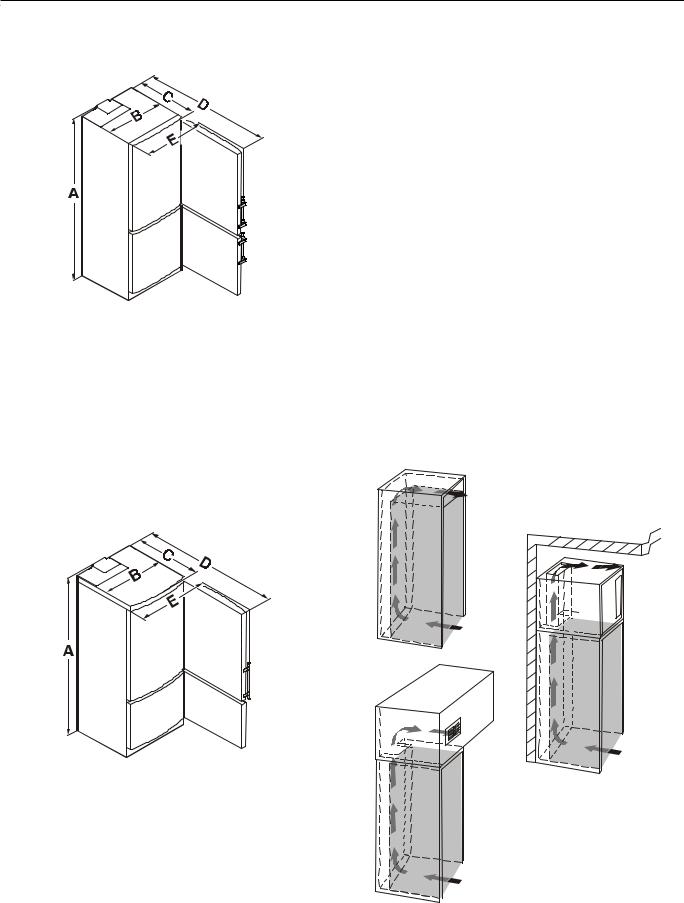
Unit Dimensions CS 1640 - Figure 1 Unit Venting - Figure 3
Figure 1 |
A = 79-1/2" (2020 mm) |
|
B = 29-3/8" (747 mm) |
||
|
||
|
C = 24-13/16" (630 mm) |
|
|
D = 52-3/8" (1330 mm) |
|
|
E = 31-3/32" (790 mm) |
Overall height of the appliance can be increased by a maximum of 5/8” (see Leveling the appliance).
Unit Dimensions CS 1400 - Figure 2
Do not restrict the air flow. The opening can either be directly over the appliance 1, above the cabinet and below the ceiling 2 or through a vent installed in a soffit 3.
The cabinet height as specified at 80” (2032 mm) will create a 1-5/16” (33 mm) gap above the appliance providing optimal air flow over the top of the appliance for its efficient operation.
To have the same air flow for CS 1400 appliances, the cabinet opening height must be
73-3/4" minimum.
Be sure to consider the possibility of having to raise some of the leveling legs in order to level the appliance when installing. If you adjust the height of the appliance - it will effectively reduce air flow. Therefore leave yourself some room for adjustment.
IMPORTANT
The section below the freezer door and the floor must not be covered.
1 


 2
2
Figure 2 |
A = 73-1/4" (1860 mm) |
3 |
B = 29-3/8" (747 mm) |
|
|
|
|
|
|
C = 24-13/16" (630 mm) |
|
|
D = 52-3/8" (1330 mm) |
|
|
E = 31-3/32" (790 mm) |
|
Overall height of the appliance can be increased by |
Figure 3 |
|
a maximum of 5/8” (see Leveling the appliance). |
||
4
Planning Information
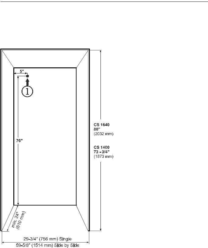
Cabinet Opening Dimensions - Figure 4
The appliance can be used freestanding or semi built-in.
If semi built-in, please consider the cabinet opening dimensions as shown in Figure 4.
1 This is where the power cord is fed out of the appliance rear.
Free length of the power cord is 94".
Choose the position of the electrical outlet taking these specifications into account.
The electrical outlet must be accessible for installation and servicing.
The electrical outlet must not be situated behind the appliance!
NOTE
Figure 4 If the gap between the rear of the appliance and the wall is less than 2 inch (51 mm) , the power consumption level may increase.
5
Installation
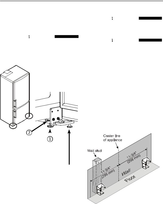
Leveling the Appliance - Figure 5
1.The height can be adjusted in front by twisting the leveling feet 1.
2.Twist the adjusting bolt 2 to set up the back of the appliance.

 CAUTION!
Do not use a power driver.
3.Align the appliance with sides of kitchen cabinets by adjusting leveling feet 1and the supports 2.
Figure 5 |
|
|
|
5 mm |
|||
|
|||
|
socket |
||
|
22 mm |
||
|
wrench |
||
IMPORTANT
After final installation, this screw must be turned down until it has proper floor contact to support the hinge bracket.
Mounting the anti tipping device

 WARNING!
The anti tipping brackets must be mounted to prevent the appliance from tipping when the fully stocked door is opened.

 WARNING!
Be sure that there is no plumbing or electrical wiring located in this area which screws or drills could damage.
The anti tipping brackets provided can be mounted within 11-3/4 inch to the left and right of the appliance center (Figure 6).
Freestanding applications
1.Mark the center of the appliance on the back wall.
2.Mount the anti tipping brackets within the given area.
IMPORTANT
Locate at least one anti tipping bracket directly in line with a wall stud (Figure 6).
To ensure a secure mounting of the brackets, use any possible mounting option as shown in
Figures 8 - 11.
Figure 6
6

Blocking for Safety
Semi built-in
With semi built-in applications the anti tipping brackets must be mounted with a distance of 22 inches from the appliance housing front to the back of the bracket (Figure 7).
The gap to the wall must be filled with a wooden spacer to fasten the bracket.

 WARNING!
Be sure the wooden spacer is fastened securely to the floor.
1.Mark the center of the appliance on the back wall.
2.Mount the wooden spacer.
3.Mount the anti tipping brackets within 11-3/4 inch to the left and right of the appliance center.
IMPORTANT
To ensure a secure mounting of the brackets use any possible mounting option as shown in
Figures 8 - 11.
Mounting Options
Mounting the bracket with the wall stud.
Mounting with wall plugs at concrete walls (Figure 8).
Screws 6 x 63 mm
Figure 8
Mounting with the wall plate turning in the screws at an angle
(Figure 9).
Screws 6 x 63 mm
Figure 9
Mounting with wooden floors
(Figure 10).
Screws 6 x 63 mm
Figure 10
Mounting with concrete floors using the anchors provided (Figure 11).
Figure 11
NOTE
If longer or shorter screws are needed, they have to be supplied by the installer.
Figure 7
7
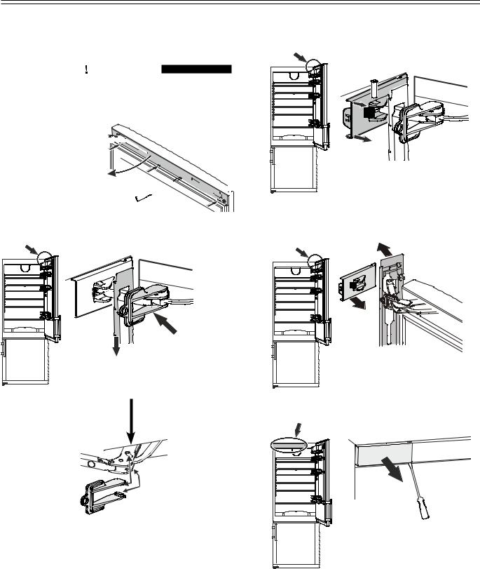
Reversing Door Hinges
Door hinges should only be changed by a trained expert. Changing the door hinges must be done by two people.

 CAUTION!
Before changing over door hinges, disconnect the appliance from the electrical outlet.
1. Open top door, prise off 


 door cover and pivot to
 the left.
1. 


2. |
3. |
|
2. Let door cover hang down.
3. Slide red safety bracket over the hinge.
IMPORTANT
The two knobs on the safety bracket must be fully inserted into the marked openings on the hinge.
5. 
4.
4.Pull the left-hand side of the cover approx. 1/4" (6 mm) towards you.
5.Remove pin.
6.
6.Open top door wide and remove covers.
7.


7.Remove cover.
8

Reversing Door Hinges
8.


8.Remove cover from upper door mounting and unscrew door.
10.
9.
9.Transfer fastener for soft stop mechanism to the opposite side.
10.Transfer cover plate to the opposite side.


 11.
11.
11. Remove cover.
12.
12. Open bottom door, prise off door cover.

 14. 15.


13.
13. Pivot door cover to the left.
14. Slide red safety bracket over the hinge.
15. Remove pin.
 16.
16.


16. Open bottom door wide and remove cover.
9
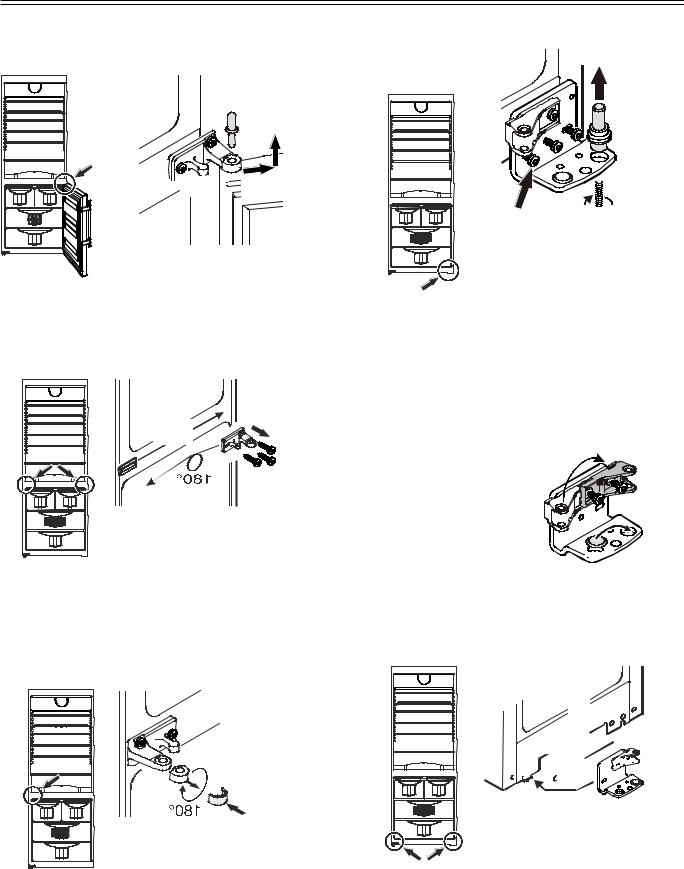
Reversing Door Hinges

 17.
17.


 18.
18.
17.Pull out middle hinge pin.
18.Remove bottom door.
20. |
19. |
|
21.
19. Unscrew hinge bracket.
20. Transfer cover plate to the opposite side.
21. Turn hinge bracket through 180° and screw into place.
22.
22.Remove hinge bushing, turn through 180° and re-fit.
24.
25. 


 23.
23.
23. Tilt appliance slightly backwards and unscrew the adjustable foot.
24.Remove the hinge pin.
25.Unscrew hinge bracket.
26. Transfer fastener for |
26. |
soft stop mechanism |
|
on hinge bracket to |
|
the opposite side. |
|
27. Transfer cover to the opposite side.

 27.
27.
28. 


 29.
29.
28. Transfer cover plate to the opposite side.
29.Screw hinge bracket into place.
10
Reversing Door Hinges
30. 
30. Tilt appliance slightly backwards, insert pin and attach using the adjustable foot.
|
31. |
|
|
|
32. |
31. |
Release pressure plates at |
32. |
|
||
|
the front 1 and pull them |
|
|
backwards to remove 2. |
|
32. |
Transfer door handle and |
|
|
plugs to the opposite side. |
|
Both doors |
35. |
|
34. 36. |
||
34. Remove screw. |
35.Pivot soft stop mechanism outwards on the right, pull to the right and remove.
36.Slide spacer to the left and remove.
37. 


38.
Both doors
37. Turn spacer through 180° and re-fit on the opposite side.
38.Turn soft stop mechanism through
180° and re-fit on the opposite side.
Then secure both parts with screws.
33.Transfer panels of both door covers to the opposite side.
33.


 39.
39. 

 33.
33.


39. Suspend bottom door on hinge pin.
11

Reversing Door Hinges
 40.
40.
40. Insert middle hinge pin.

 41.
41.
41.Slide door cover over soft stop mechanism hinge.
42.
43.

44.
42.Move soft stop mechanism hinge to the fastener and insert pin.
43.Remove red safety bracket.
44.Pivot door cover to the left and click into place on the door.
45. 

45. Click cover into place.
Refrigerator door |
46. |
46. Using a screwdriver, push |
|
out the hinge from under- |
|
neath and remove it from |
|
the door . |
|
Refrigerator door |
47. |
47. Using a screwdriver, push out the plug from underneath and transfer it to the opposite side.
Refrigerator door |
48. |
48. Insert hinge. |
12
 Loading...