


 Loading...
PF-730
SERVICE MANUAL
Published in February 2011
843NJ110
3NJSM060
First Edition
CAUTION
RISK OF EXPLOSION IF BATTERY IS REPLACED BY AN INCORRECT TYPE. DISPOSE OF USED BATTERIES ACCORDING TO THE INSTRUCTIONS.
It may be illegal to dispose of this battery into the municipal waste stream. Check with your local solid waste officials for details in your area for proper disposal.
ATTENTION
IL Y A UN RISQUE D’EXPLOSION SI LA BATTERIE EST REMPLACEE PAR UN MODELE DE TYPE INCORRECT. METTRE AU REBUT LES BATTERIES UTILISEES SELON LES INSTRUCTIONS DONNEES.
Il peut être illégal de jeter les batteries dans des eaux d’égout municipales. Vérifiez avec les fonctionnaires municipaux de votre région pour les détails concernant des déchets solides et une mise au rebut appropriée.
Revision history
Revision |
Date |
Replaced pages |
Remarks |
|
|
|
|
|
|
|
|

This page is intentionally left blank.

Safety precautions
This booklet provides safety warnings and precautions for our service personnel to ensure the safety of their customers, their machines as well as themselves during maintenance activities. Service personnel are advised to read this booklet carefully to familiarize themselves with the warnings and precautions described here before engaging in maintenance activities.

Safety warnings and precautions
Various symbols are used to protect our service personnel and customers from physical danger and to prevent damage to their property. These symbols are described below:
 DANGER: High risk of serious bodily injury or death may result from insufficient attention to or incorrect compliance with warning messages using this symbol.
 WARNING: Serious bodily injury or death may result from insufficient attention to or incorrect compliance with warning messages using this symbol.
 CAUTION: Bodily injury or damage to property may result from insufficient attention to or incorrect compliance with warning messages using this symbol.
Symbols
The triangle ( ) symbol indicates a warning including danger and caution. The specific point of attention is shown inside the symbol.
General warning. |
Warning of risk of electric shock. |
Warning of high temperature.
 indicates a prohibited action. The specific prohibition is shown inside the symbol.
General prohibited action. |
Disassembly prohibited. |
 indicates that action is required. The specific action required is shown inside the symbol.
General action required. |
Remove the power plug from the wall outlet. |
Always ground the copier.

1. Installation Precautions
 WARNING
•Do not use a power supply with a voltage other than that specified. Avoid multiple connections to one outlet: they may cause fire or electric shock. When using an extension cable, always check that it is adequate for the rated current. .....................................................................................................
•Connect the ground wire to a suitable grounding point. Not grounding the copier may cause fire or electric shock. Connecting the earth wire to an object not approved for the purpose may cause explosion or electric shock. Never connect the ground cable to any of the following: gas pipes, lightning rods, ground cables for telephone lines and water pipes or faucets not approved by the proper authorities. ..........................................................................................................................................
 CAUTION:
•Do not place the copier on an infirm or angled surface: the copier may tip over, causing injury. .........
•Do not install the copier in a humid or dusty place. This may cause fire or electric shock. .................
•Do not install the copier near a radiator, heater, other heat source or near flammable material. This may cause fire. ...................................................................................................................................
•Allow sufficient space around the copier to allow the ventilation grills to keep the machine as cool as possible. Insufficient ventilation may cause heat buildup and poor copying performance. ............
•Always handle the machine by the correct locations when moving it. .................................................
•Always use anti-toppling and locking devices on copiers so equipped. Failure to do this may cause the copier to move unexpectedly or topple, leading to injury. ..............................................................
•Avoid inhaling toner or developer excessively. Protect the eyes. If toner or developer is accidentally ingested, drink a lot of water to dilute it in the stomach and obtain medical attention immediately. If it gets into the eyes, rinse immediately with copious amounts of water and obtain medical atten-
tion. .....................................................................................................................................................
•Advice customers that they must always follow the safety warnings and precautions in the copier’s instruction handbook. .........................................................................................................................

2. Precautions for Maintenance
 WARNING
•Always remove the power plug from the wall outlet before starting machine disassembly. ................
•Always follow the procedures for maintenance described in the service manual and other related brochures. ..........................................................................................................................................
•Under no circumstances attempt to bypass or disable safety features including safety mechanisms and protective circuits. ........................................................................................................................
•Always use parts having the correct specifications. ............................................................................
•Always use the thermostat or thermal fuse specified in the service manual or other related brochure when replacing them. Using a piece of wire, for example, could lead to fire or other serious accident. ...................................................................................................................................................
•When the service manual or other serious brochure specifies a distance or gap for installation of a part, always use the correct scale and measure carefully. ..................................................................
•Always check that the copier is correctly connected to an outlet with a ground connection. ...............
•Check that the power cable covering is free of damage. Check that the power plug is dust-free. If it is dirty, clean it to remove the risk of fire or electric shock. .................................................................
•Never attempt to disassemble the optical unit in machines using lasers. Leaking laser light may damage eyesight. ...............................................................................................................................
•Handle the charger sections with care. They are charged to high potentials and may cause electric shock if handled improperly. ...............................................................................................................
 CAUTION
•Wear safe clothing. If wearing loose clothing or accessories such as ties, make sure they are safely secured so they will not be caught in rotating sections. ......................................................................
•Use utmost caution when working on a powered machine. Keep away from chains and belts. ..........
•Handle the fixing section with care to avoid burns as it can be extremely hot. ..................................
•Check that the fixing unit thermistor, heat and press rollers are clean. Dirt on them can cause abnormally high temperatures. ...........................................................................................................

•Do not remove the ozone filter, if any, from the copier except for routine replacement. ......................
•Do not pull on the AC power cord or connector wires on high-voltage components when removing them; always hold the plug itself. ........................................................................................................
•Do not route the power cable where it may be stood on or trapped. If necessary, protect it with a cable cover or other appropriate item. ................................................................................................
•Treat the ends of the wire carefully when installing a new charger wire to avoid electric leaks. ..........
•Remove toner completely from electronic components. .....................................................................
•Run wire harnesses carefully so that wires will not be trapped or damaged. ......................................
•After maintenance, always check that all the parts, screws, connectors and wires that were removed, have been refitted correctly. Special attention should be paid to any forgotten connector, trapped wire and missing screws. .......................................................................................................
•Check that all the caution labels that should be present on the machine according to the instruction handbook are clean and not peeling. Replace with new ones if necessary. .......................................
•Handle greases and solvents with care by following the instructions below: ......................................
·Use only a small amount of solvent at a time, being careful not to spill. Wipe spills off completely.
·Ventilate the room well while using grease or solvents.
·Allow applied solvents to evaporate completely before refitting the covers or turning the power switch on.
·Always wash hands afterwards.
•Never dispose of toner or toner bottles in fire. Toner may cause sparks when exposed directly to fire in a furnace, etc. ...........................................................................................................................
•Should smoke be seen coming from the copier, remove the power plug from the wall outlet immediately. ...................................................................................................................................................
3. Miscellaneous
 WARNING
•Never attempt to heat the drum or expose it to any organic solvents such as alcohol, other than the specified refiner; it may generate toxic gas. ........................................................................................
•Keep the machine away from flammable liquids, gases, and aerosols. A fire or an electric shock might occur. ........................................................................................................................................

This page is intentionally left blank.
|
|
3NJ |
|
CONTENTS |
|
1-1 Specifications |
|
|
1-1-1 Specifications ........................................................................................................................ |
1-1-1 |
|
1-1-2 Parts names .......................................................................................................................... |
1-1-2 |
|
1-1-3 Machine cross section ........................................................................................................... |
1-1-3 |
|
1-2 Installation |
|
|
1-2-1 Installation environment......................................................................................................... |
1-2-1 |
|
1-2-2 Unpacking.............................................................................................................................. |
1-2-2 |
|
(1) |
Precaution for unpacking.................................................................................................. |
1-2-2 |
1-2-3 Unpacking.............................................................................................................................. |
1-2-3 |
|
(1) |
Unpacking......................................................................................................................... |
1-2-3 |
(2) |
Remove the tapes and pad .............................................................................................. |
1-2-4 |
1-2-4 Installing the cassette heater (Option)................................................................................... |
1-2-6 |
|
1-3 Maintenance Mode |
|
|
1-3-1 Maintenance mode ................................................................................................................ |
1-3-1 |
|
(1) |
Executing a maintenance item ......................................................................................... |
1-3-1 |
(2) |
Maintenance modes item list ............................................................................................ |
1-3-2 |
(3) |
Contents of the maintenance mode items ........................................................................ |
1-3-3 |
1-4 Troubleshooting |
|
|
1-4-1 Paper mis feed detection....................................................................................................... |
1-4-1 |
|
(1) |
Paper mis feed indication ................................................................................................. |
1-4-1 |
(2) |
Paper mis feed detection condition .................................................................................. |
1-4-1 |
1-4-2 Self-diagnostic function ......................................................................................................... |
1-4-5 |
|
(1) |
Self-diagnostic function .................................................................................................... |
1-4-5 |
(2) |
Self diagnostic codes........................................................................................................ |
1-4-5 |
1-4-3 Electric problems ................................................................................................................... |
1-4-8 |
|
1-4-4 Mechanical problems........................................................................................................... |
1-4-10 |
|
1-5 Assembly and Disassembly |
|
|
1-5-1 Precautions for assembly and disassembly........................................................................... |
1-5-1 |
|
(1) |
Precautions....................................................................................................................... |
1-5-1 |
1-5-2 Paper feed section................................................................................................................. |
1-5-2 |
|
(1) |
Detaching and refitting the PF forwarding, PF paper feed and PF separation pulleys..... |
1-5-2 |
1-5-3 PWBs..................................................................................................................................... |
1-5-7 |
|
(1) |
Detaching and refitting the PF main PWB ........................................................................ |
1-5-7 |
1-5-4 Driving section ....................................................................................................................... |
1-5-9 |
|
(1) |
Detaching and refitting the PF Driving unit ....................................................................... |
1-5-9 |
(2) |
Detaching and refitting the PF lift motors ....................................................................... |
1-5-10 |
2-1 Mechanical Construction |
|
|
2-1-1 Mechanical construction ........................................................................................................ |
2-1-1 |
|
2-2 Electrical Parts Layout
2-2-1 Electrical parts layout ............................................................................................................ |
2-2-1 |
|
(1) |
PWB and sensors............................................................................................................. |
2-2-1 |
(2) |
Motors and others............................................................................................................. |
2-2-3 |
|
|
|
3NJ |
2-3 |
Operation of the PWBs |
|
|
|
2-3-1 |
PF main PWB ........................................................................................................................ |
2-3-1 |
2-4 |
Appendixes |
|
|
|
2-4-1 |
Appendixes............................................................................................................................ |
2-4-7 |
|
|
(1) Wiring diagram ................................................................................................................. |
2-4-7 |
3NJ
1-1-1 Specifications
Item |
Specifications |
|
|
|
|
Paper weight |
64 to 256g/m2 |
|
Paper types |
Plain (80g/m2 or less), Thick (256g/m2 or less), recycled |
|
Paper size |
A3, B4, A4, A4R, B5, B5R, A5R, Folio, Ledger, Legal, OficioII, 8.5 × 13.5", |
|
Letter, LetterR, Excutive, StatementR, 8K, 16K, 16KR |
||
|
||
|
|
|
Paper capacity |
1000 sheets (500 sheets x 2) (80g/m2) |
|
Dimensions |
598 (W) x 315 (H) x 699.6 (D) mm |
|
23 9/19” (W) x 12 3/8” (H) x 27 9/16” (D) |
||
|
||
|
|
|
Weight |
Approx. 30kg / Approx. 66.1 lbs |
|
|
|
|
Power source |
Electrically connected to the machine. (3.3 V DC, 24 V DC) |
|
|
|
NOTE: These specifications are subject to change without notice.
1-1-1

3NJ
1-1-2 Parts names
2
6 |
4 |
4
5
1
3
Figure 1-1-1
1. |
PF paper conveying guide |
4. |
PF paper size width guides |
2. |
Cassette 3 |
5. |
PF paper size width adjusting tab |
3. |
Cassette 4 |
6. |
PF paper size length guide |
1-1-2
3NJ
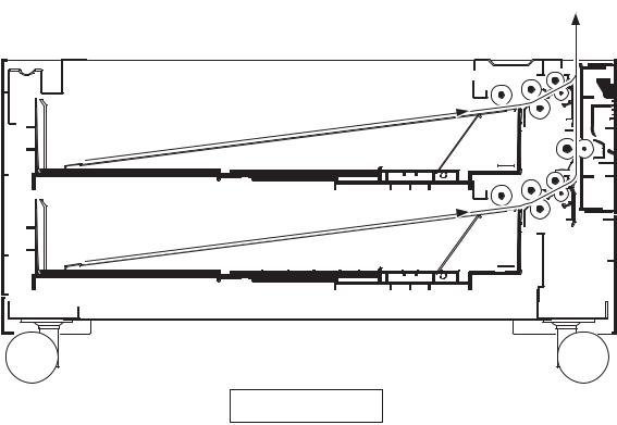
1-1-3 Machine cross section
 Paper path
Figure 1-1-2
1-1-3

3NJ
This page is intentionally left blank.
1-1-4
3NJ
1-2-1 Installation environment
Installation location (Be based on the machine establishment place.)
Avoid direct sunlight or bright lighting. Ensure that the photo conductor will not be exposed to direct sunlight or other strong light when removing paper jams.
Avoid locations subject to high temperature and high humidity or low temperature and low humidity; an abrupt change in the environmental temperature; and cool or hot, direct air.
Avoid places subject to dust and vibrations.
Choose a surface capable of supporting the weight of the machine.
Place the machine on a level surface (maximum allowance inclination: 1°).
Avoid air-borne substances that may adversely affect the machine or degrade the photo conductor, such as mercury, acidic of alkaline vapors, inorganic gasses, NOx, SOx gases and chlorine-based organic solvents. Select a well-ventilated location.
1-2-1
3NJ
1-2-2 Unpacking
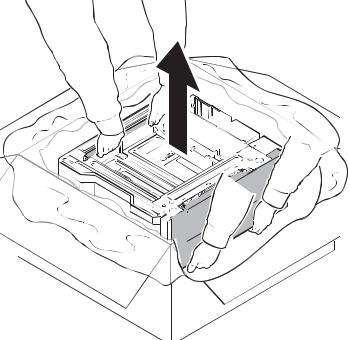
(1) Precaution for unpacking
Hold the positions shown in the figure and remove the paper feeder from the outer case.
Figure 1-2-1
1-2-2
3NJ
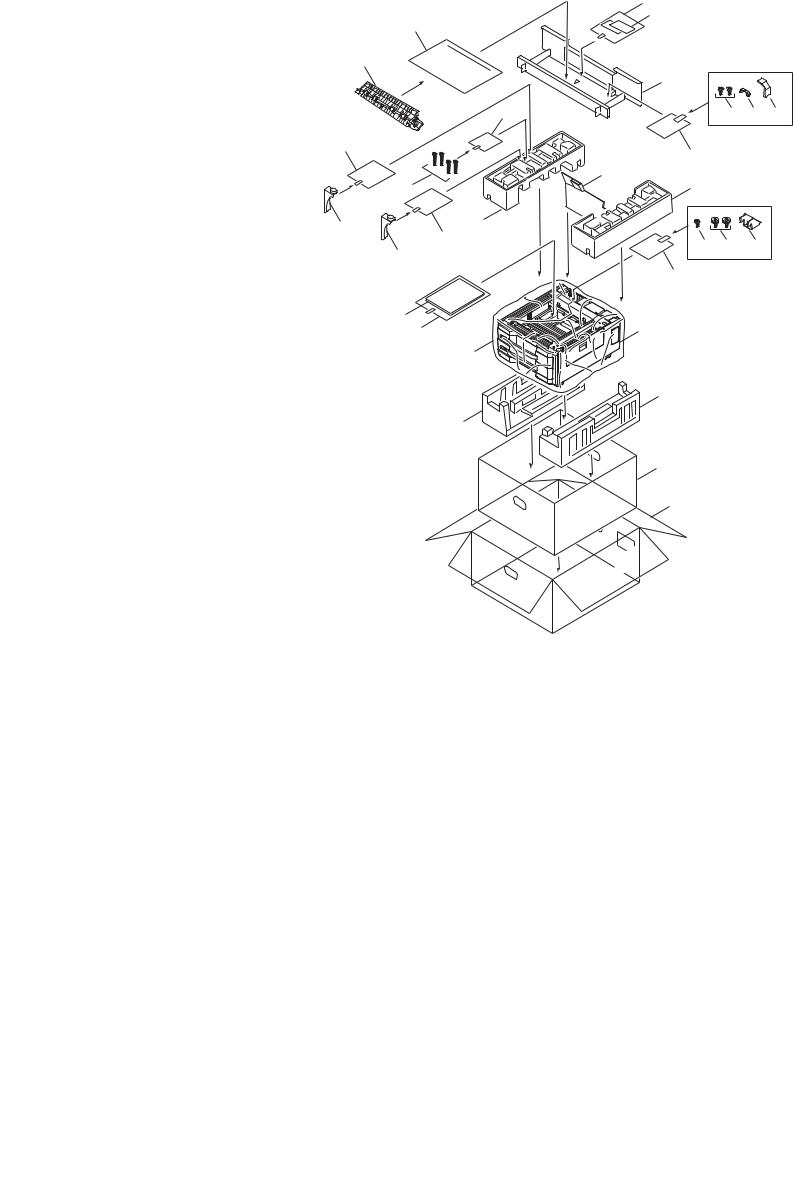
1-2-3 Unpacking
(1) Unpacking
|
|
|
|
13 |
|
15 |
|
|
|
14 |
|
|
|
|
|
|
|
16 |
|
|
|
12 |
|
|
|
|
|
|
|
|
|
27 |
|
18 19 20 |
|
|
|
|
|
||
25 |
|
|
|
17 |
|
|
|
|
8 |
|
|
28 |
|
|
7 |
|
|
|
|
|
|
||
26 |
25 |
6 |
|
|
|
|
|
22 23 |
24 |
||
26 |
|
|
|||
|
|
|
|||
|
|
|
|
|
|
|
|
|
|
21 |
|
11 10 |
|
|
|
1 |
|
|
|
9 |
|
|
|
|
|
|
|
5 |
|
|
4 |
|
|
|
|
|
|
|
|
3 |
|
|
|
|
|
2 |
|
|
|
Figure 1-2-2 Unpacking |
|
|
|
1. |
Paper feeder |
11. |
Installation guide |
21. |
Plastic bag |
2. |
Outer case |
12. |
Accessory box |
22. |
S tight screws M4 x 8B |
3. |
Inner case |
13. |
Plastic bag |
23. |
Pins |
4. |
Bottom left pad |
14. |
Paper size plates |
24. |
Retainer |
5. |
Bottom right pad |
15. |
Plastic bag |
25. |
Plastic bag |
6. |
Upper left pad |
16. |
Middle roller unit |
26. |
Supporting plate |
7. |
Upper right pad |
17. |
Plastic bag |
27. |
Plastic bag |
8. |
Rear pad |
18. |
S tight screw M4 x 8B |
28. |
S tight screws M4 x 20B |
9. |
Machine cover |
19. |
Clamp |
|
|
10. |
Plastic bag |
20. |
Wire cover |
|
|
Caution: Place the machine on a level surface. See the Installation Guide for installation.
1-2-3
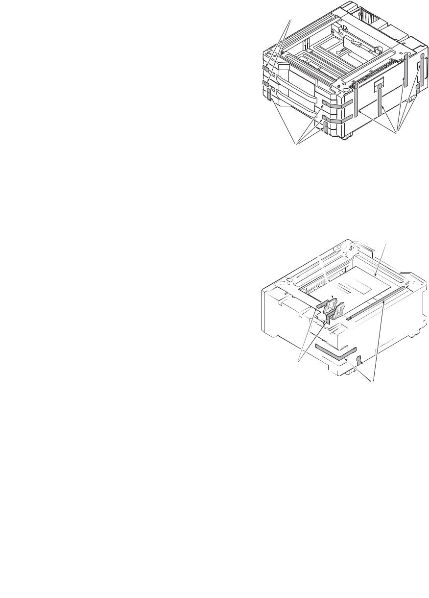
(2) Remove the tapes and pad
Procedure
1. Remove eleven tapes.
2.Remove five tapes and then remove the retainer and the leaflet.
3NJ
Tapes
Tapes
Tapes
Figure 1-2-3
Retainer
Leaflet
Tapes
Tapes
Figure 1-2-4
1-2-4
3.Pull the upper cassette forward.
4.Remove the tape.
5.Remove the pad from cassette.
3NJ
Pad
Tape
Cassette
6.Remove the lift plate stopper from cassette and attach it to the storage location.
*: When moveing the machine,attach the lift plate in original position.
7.Gently push cassette back in.
8.Repeat steps 3 to 7 similarly for lower cassette.
Figure 1-2-5
Lift plate stopper
Cassette
Figure 1-2-6
1-2-5
3NJ
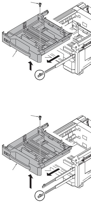
1-2-4 Installing the cassette heater (Option)
Procedure
1. Pull the cassette 3 forward.
2. Remove the pin and then remove the |
Pin |
cassette 3. |
|
Cassette 3
Figure 1-2-7
3. |
Pull the cassette 4 forward. |
Pin |
4. |
Remove the pin and then remove the |
|
cassette 4.
Cassette 4
Figure 1-2-8
1-2-6
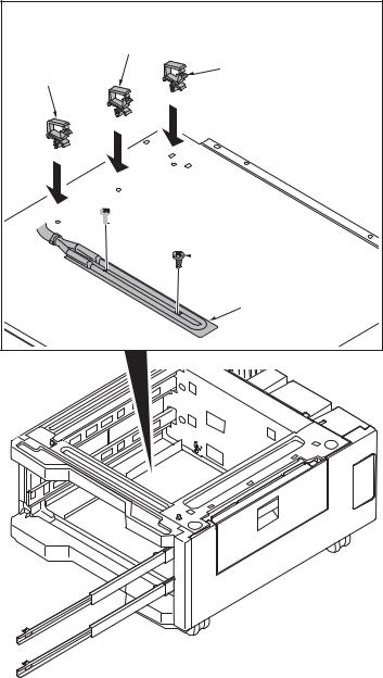
5.Install three wire saddles on the bottom frame of the paper feeder.
6.Install the cassette heater by using two screws.
3NJ
Wire saddle
Wire saddle
Wire saddle

 Screw
Screw
 Screw
Screw
Cassette heater
Figure 1-2-9
1-2-7
3NJ
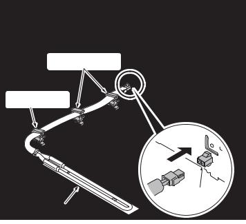
7. Connect the connector of the cassette heater to the connector in the rear frame of the paper feeder.
8. Pass through the wire of the cassette heater to three wire saddles.
Wire saddles
Wire saddle
Connector
Cassette heater
Figure 1-2-10
1-2-8
3NJ
1-3-1 Maintenance mode
The machine is equipped with a maintenance function which can be used to maintain and service the machine.
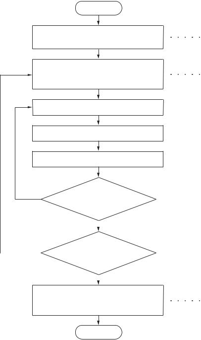
(1) Executing a maintenance item
Start
Enter “10871087” using the numeric keys.
Enter the maintenance item number using the cursor up/down keys
or numeric keys.
Press the start key.
The selected maintenance item is run.
Press the stop key.
Yes |
Repeat the same |
||
|
maintenance item? |
||
Yes |
|
No |
|
|
|||
|
|||
Run another maintenance |
|||
|
|||
|
|||
|
item? |
||
|
|
No |
|
|
|
||
Enter 001 using the cursor up/down keys or numeric keys and press the start key.
Maintenance mode is entered.
The maintenance item is selected.
Maintenance mode is exited.
End
1-3-1
3NJ
(2) Maintenance modes item list
Section |
Item |
Content of maintenance item |
Initial setting |
|
|
No. |
|
|
|
|
|
|
|
|
General |
U000 |
Outputting an own-status report |
- |
|
|
|
|
|
|
|
U001 |
Exiting the maintenance mode |
- |
|
|
|
|
|
|
|
U019 |
Displaying the ROM version |
- |
|
|
|
|
|
|
Drive, |
U034 |
Adjusting the print start timing |
|
|
paper feed |
|
LSU Out Top |
0/0/0/0/0/0/0/0/0/0/0/0 |
|
and paper |
|
|||
|
LSU Out Left |
0/0/0/0/0/0/0/0/0 |
||
conveying |
|
|||
system |
|
LSU Out Top B/W |
0/0/0/0/0/0 |
|
|
|
LSU Out Top 3/4 |
0/0/0/0/0/0 |
|
|
|
|
|
|
Operation |
U247 |
Setting the paper feed device |
- |
|
panel and |
|
|
|
|
support |
|
|
|
|
equipment |
|
|
|
|
|
|
|
|
|
Mode |
U327 |
Setting the cassette heater control |
Off |
|
setting |
|
|
|
|
U341 |
Specific paper feed location setting for printing |
- |
||
|
||||
|
|
function |
|
|
|
|
|
|
|
Others |
U901 |
Checking copy counts by paper feed locations |
- |
|
|
|
|
|
1-3-2
Loading...