


TV-20F242

SERVICE MANUAL
TV/VCR COMBO
TV-20F242
TV-20F242
CONTENTS
SPECIFICATIONS 2
OPERATING INSTRUCTIONS (APPENDED)
SAFETY PRECAUTIONS
SPECIFIC SERVICE INSTRUCTIONS 4
SERVICE ADJUSTMENTS 18
GUIDE FOR REPAIRING
STANDARD CIRCUIT DIAGRAM (APPENDED)
PARTS LIST
COPYRIGHT © 2000 VICTOR COMPANY OF JAPAN, LTD.
3
30
53
No. 51768
Nov. 2000

SPECIFICATIONS
TELEVISION
Picture Tube: 20" (measured diagonally)
Tuner Type: Quartz PLL Frequency Synthesized
Receiving Channels: VHF 2-13
UHF 14-69
CATV 14-36 (A)-(W)
37-59 (AA)-(WW)
60-85 (AAA)-(ZZZ)
86-94 (86)-(94)
95-99 (A-5)-(A-1)
100-125 (100)-(125)
01 (5A)
Antenna Input: VHF/UHF In 75 ohms coaxial
Speaker: 3", 8 ohms x 2
Audio Output Power: 1.5 + 1.5 W
VCR
Video System: VHS ,4 Rotary Heads Helical scanning System
Video Signal: NTSC Color
Cassette Tape: VHS
Video Head: 4 Head
Audio Track: Hi-Fi Sound - 2 Tracks
MONO Sound - 1 Tracks
Tape Speed: SP:33.35mm/sec
EP:11.12mm/sec
F.FWD/REW Time: Approx. 1 minutes and 48 seconds (T-120 Cassette)
Speed Search: SP 3&5 X Normal Speed
EP 9&15 X Normal Speed
GENERAL
Power Source: AC 120V 60Hz
Power Consumption: 115 Watts
Dimensions: W 19-3/4" x D 19" x H 20-1/4"
Weight: 55.2 Ibs
Inputs/Outputs: Video: In (RCA) 1Vp-p 75 ohm
Out (RCA) 1Vp-p 75 ohm
Audio: In (RCA) 300 mV/50K ohm
Out (RCA) 300 mV/1K ohm
Headphone Jack: 3.5mm Stereo mini-jack
Storage Temperature -20 ∫C ~ 60 ∫C
Operating Temperature 5 ∫C ~ 40 ∫C
Accessories:
Remote Control X 1
Batteries (AA) X 2
Design & specification are subject to change without notice.
2

SAFETY PRECAUTIONS
Operating the receiver outside of its cabinet or with its
back removed involves a shock hazard. Work on
these models should only be performed by those who
are thoroughly familiar with precautions necessary
when working on high voltage equipment.
Exercise care when servicing this chassis with power
applied. Many B plus and high voltage RF terminals are
exposed which, if carelessly contacted, can cause
serious shock or result in damage to the chassis.
Maintain interconnecting ground lead connections
between chassis, escutcheon, picture tube dag and
tuner cluster when operating the chassis.
These receivers have a "polarized" AC line cord. The AC
plug is designed to fit into standard AC outlets in one
direction only. The wide blade connects to the "ground
side" and the narrow blade connects to the "hot side" of
the AC line. This assures that the TV receiver is properly
grounded to the house wiring. If an extension cord must
be used, make sure it is of the "polarized" type.
Since the chassis of this receiver is connected to one
side of the AC supply during operation, service should
not be attempted by anyone not familiar with the
precautions necessary when working on these types
of equipment.
When it is necessary to make measurements or tests with
AC power applied to the receiver chassis, an Isolation
Transformer must be used as a safety precaution and to
prevent possible damage to transistors. The Isolation
Transformer should be connected between the TV line
cord plug and the AC power outlet.
Certain HV failures can increase X-ray radiation.
Receivers should not be operated with HV levels
exceeding the specified rating for their chassis type. The
maximum operating HV specified for the chassis used in
these receivers is 32kV 1.0kV at zero beam current with
a line voltage of 120V AC. Higher voltage may also
increase the possibility of failure in the HV supply.
It is important to maintain specified values of all
components in the horizontal and high voltage circuits
and anywhere else in the receiver that could cause a rise
in high voltage, or operating supply voltages. No changes
should be made to the original design of the receiver.
Components shown in the shaded areas on the
schematic diagram and/or identified by ! in the
replacement parts list should be replaced only with
exact factory recommended replacement parts. The
use of unauthorized substitute parts may create
shock, fire, X-ray radiation, or other hazards.
The picture tube used in this receiver employs integral
implosion protection. Replace with a tube of the same
type number for continued safety. Do not lift picture
tube by the neck. Handle the picture tube only when
wearing shatterproof goggles and after discharging the
high voltage completely. Keep others without
shatterproof goggles away.
When removing springs or spring mounted parts from the
tuner, tuner cluster or chassis, shatterproof goggles must
be worn. Keep others without shatterproof goggles away.
Before returning the receiver to the user, perform the
following safety checks:
1.
Inspect all lead dress to make certain that leads are
not pinched or that hardware is not lodged between
the chassis and other metal parts in the receiver.
2.
Replace all protective devices such as nonmetallic
control knobs, insulating fishpapers, cabinet backs,
adjustment and compartment covers or shields,
isolation resistor-capacitor networks, mechanical
insulators, etc.
3.
To be sure that no shock hazard exists, a check for
the presence of leakage current should be made at
each exposed metal part having a return path to the
chassis (antenna, cabinet metal, screw heads,
knobs and/or shafts, escutcheon, etc.) in the
following manner.
Plug the AC line cord directly into a 120V AC receptacle.
(Do not use an Isolation Transformer during these
checks.) All checks must be repeated with the AC line
cord plug connection reversed. (If necessary, a
nonpolarized adapter plug must be used only for the
purpose of completing these checks.)
If available, measure current using an accurate leakage
current tester. Any reading of 0.35mA or more is
excessive and indicates a potential shock hazard which
must be corrected before returning the receiver to the
owner.
If a reliable leakage current tester is not available, this
alternate method of measurement should be used.
Using two clip leads, connect a 1500 ohm, 10 watt
resistor paralleled by a 0.15 F capacitor in series with
a known earth ground, such as a water pipe or conduit
and the metal part to be checked. Use a VTVM or
VOM with 1000 ohms per volt, or higher, sensitivity to
measure this AC voltage drop across the resistor. Any
reading of 0.35 volt RMS or more is excessive and
indicates a potential shock hazard which must be
corrected before returning the receiver to the owner.
To determine the presence of high voltage, use an
accurate high impedance HV meter connected
between the second anode lead and the CRT dag
grounding device. When servicing the High Voltage
System, remove static charges from it by connecting a
10k ohm resistor in series with an insulated wire (such
as a test probe) between the picture tube dag and 2nd
anode lead (have AC line cord disconnected from AC
supply).
TO EXPOSED
METAL PARTS
VT VM
AC SCALE
1.5K OHMS
10W
15 F
TEST PROBE
TO KNOWN
EARTH GROUND
3
SPECIFIC SERVICE INSTRUCTIONS
DISASSEMBLY INSTRUCTIONS
1. REMOVAL OF MECHANICAL PARTS
AND P.C. BOARDS
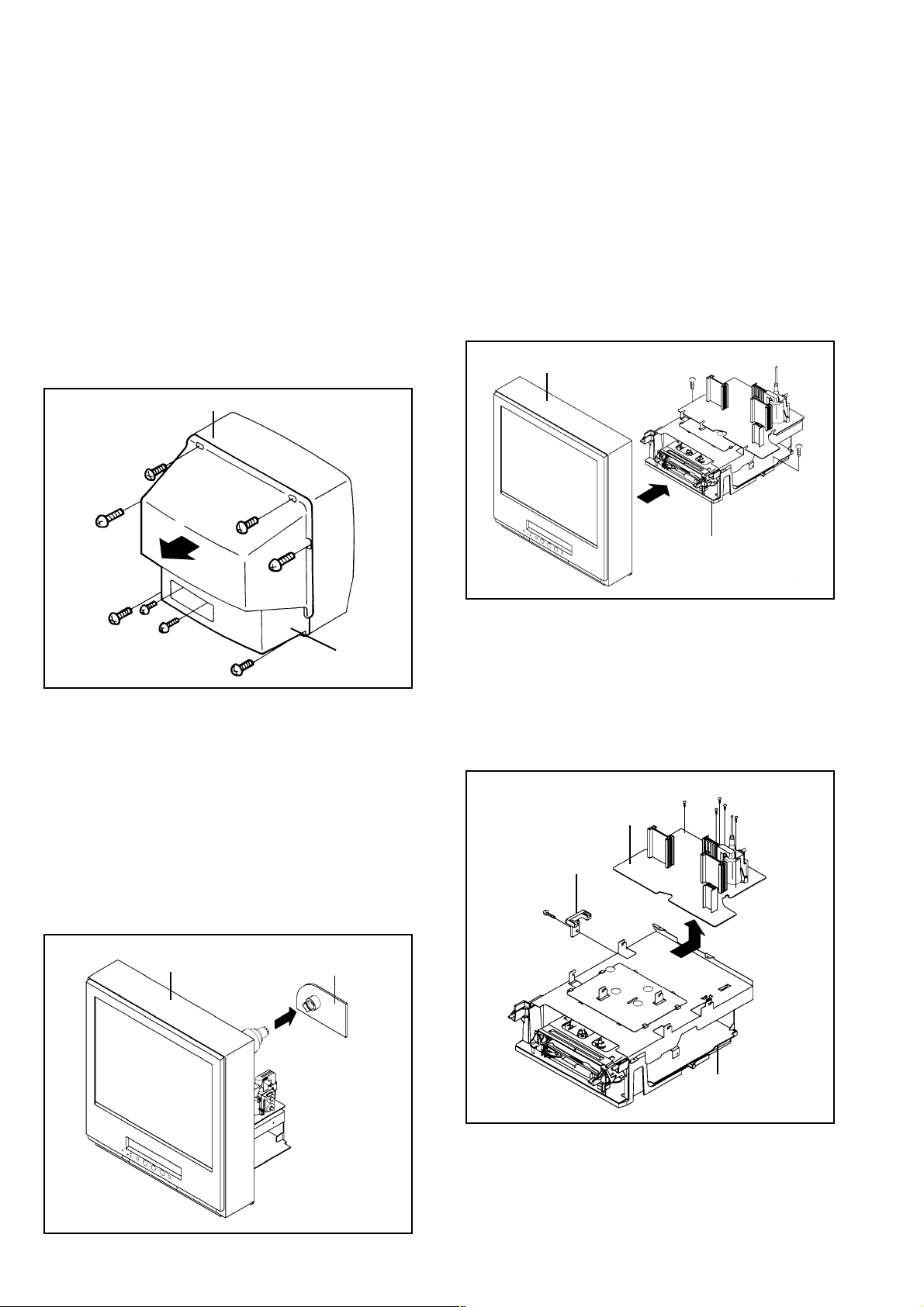
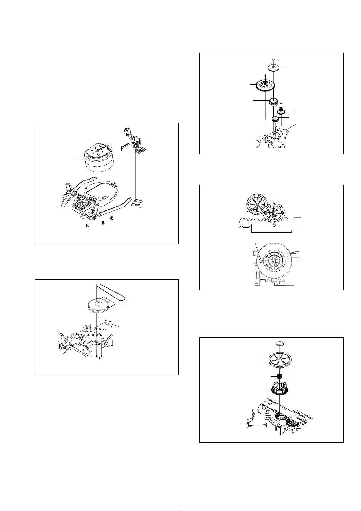
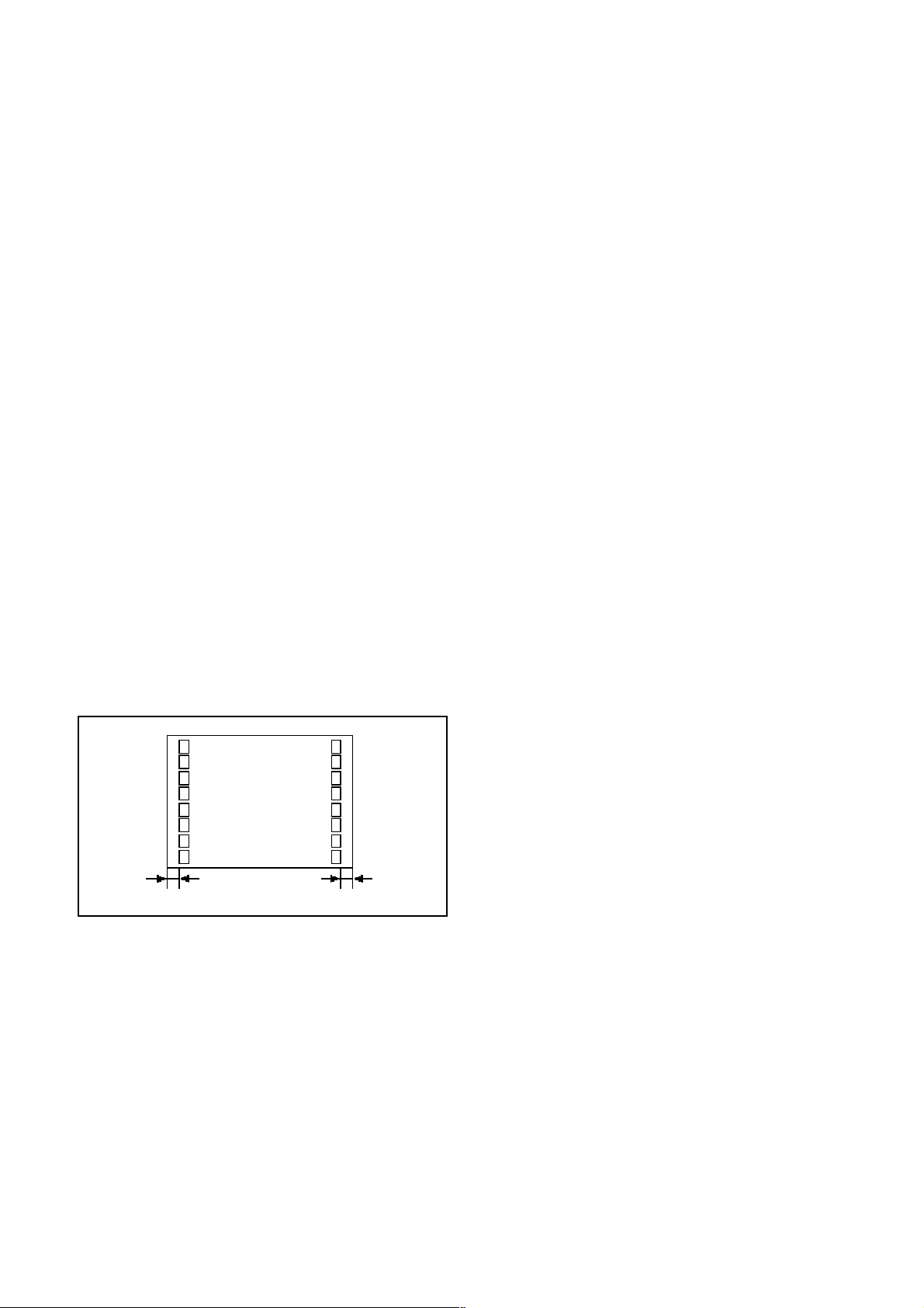
1-1: BACK CABINET (Refer to Fig. 1-1)
1.
Remove the 6 screws 1.
2.
Remove the 2 screws 2 which are used for holding the
Back Cabinet.
3.
Remove the AC cord from the AC cord hook 3.
4.
Remove the Back Cabinet in the direction of arrow.
Front Cabinet
1
1
1
1
1
2
2
1
1-2: CRT PCB (Refer to Fig. 1-2)
CAUTION: BEFORE REMOVING THE ANODE CAP,
DISCHARGE ELECTRICITY BECAUSE IT
CONTAINS HIGH VOLTAGE.
BEFORE ATTEMPTING TO REMOVE OR
REPAIR ANY PCB, UNPLUG THE POWER
CORD FROM THE AC SOURCE.
1.
Remove the Anode Cap.
(Refer to REMOVAL OF ANODE CAP)
2.
Disconnect the following connectors:
(CP802 and CP805).
3.
Remove the CRT PCB in the direction of arrow.
3
Back Cabinet
Fig. 1-1
1-3: TV/VCR BLOCK (Refer to Fig. 1-3)
1.
Remove the 2 screws 1.
2.
Disconnect the following connectors:
(CP401, CP502, CP4201 and CP4202).
3.
Unlock the support 2.
4.
Remove the TV/VCR Block in the direction of arrow.
Front Cabinet
1
TV/VCR Block
2
UP TO
RELEASE
1-4: MAIN PCB (Refer to Fig. 1-4)
1.
Remove the screw 1.
2.
Remove the Main PCB Holder.
3.
Remove the 2 screws 2.
4.
Remove the 3 screws 3.
5.
Disconnect the following connectors:
(CP810 and CP820).
6.
Remove the Main PCB in the direction of arrow.
2
2
Main PCB
Main PCB Holder
1
3
3
3
1
Fig. 1-3
Front Cabinet
CRT PCB
VCR Block
Fig. 1-4
Fig. 1-2
4
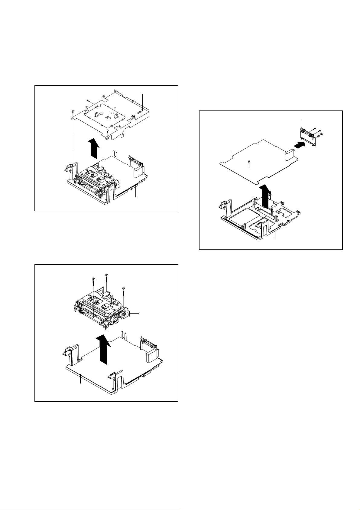
1-5: DECK SHIELD PLATE (Refer to Fig. 1-5)
1.
2.
3.
1-7: JACK PLATE AND SYSCON PCB (Refer to Fig. 1-7)
1.
2.
3.
4.
5.
6.
7.
Remove the screw 1.
Remove the Syscon PCB in the direction of arrow (A).
Remove the 2 screws 2.
Remove the nut 3.
Remove the washer 4.
Unlock the 2 supports 5.
Remove the Jack Plate in the direction of arrow (B).
Jack Plate
1
Deck Holder
Syscon PCB
(A)
5
5
(B)
4
Fig. 1-7
Remove the 2 screws 1.
Remove the screw 2.
Remove the Deck Shield Plate in the direction of arrow.
2
2
3
1
Deck Shield Plate
Fig. 1-5
1-6: DECK CHASSIS (Refer to Fig. 1-6)
1.
2.
3.
Remove the 3 screws 1.
Disconnect the following connectors:
(CP1004, CP1005, CP1006, CP4001, CP4002 and
CP4003).
Remove the Deck Chassis in the direction of arrow.
1
1
1
Deck Chassis
Syscon PCB
Fig. 1-6
1
VCR Block
2
5

2. REMOVAL OF DECK PARTS
2-1: TOP BRACKET (Refer to Fig. 2-1)
Remove the 2 screws 1.
1.
Slide the 2 supports 2 and remove the Top Bracket.
2.
NOTE
When you install the Top Bracket, install the screw (1)
first, then install the screw (2).
NOTE
When you install the Tape Guide L, install as shown in the
circle of Fig. 2-3-B. (Refer to Fig. 2-3-B)
Tape Guide L
(2)
Top Bracket
2
Main Chassis
• Screw Torque: 5 ± 0.5kgf•cm
1
Top Bracket
2
Main Chassis
(1)
1
Fig. 2-1
2-2: FLAP LEVER/TAPE GUIDE R (Refer to Fig. 2-2)
Move the Cassette Holder Ass'y to the back side.
1.
Remove the Polyslider Washer 1.
2.
Remove the Flap Lever.
3.
Unlock the 3 supports 2 and remove the Tape Guide R.
4.
Tape Guide R
Flap Lever
2
2
2
Main Chassis
1
Fig. 2-2
2-3: TAPE GUIDE L (Refer to Fig. 2-3-A)
Move the Cassette Holder Ass'y to the back side.
1.
Unlock the 2 supports 1 and remove the Tape Guide L.
2.
Remove the REC Lever.
3.
REC Lever
Fig. 2-3-B
2-4: CASSETTE HOLDER ASS'Y (Refer to Fig. 2-4)
Move the Cassette Holder Ass'y to the front side.
1.
Push the Locker R to remove the Cassette Side R.
2.
Remove the Cassette Side L.
3.
Main Chassis
Cassette Side L
Cassette Side R
Locker R
Main Chassis
Fig. 2-4
2-5: CASSETTE SIDE L/R (Refer to Fig. 2-5)
Unlock the 4 supports 1 and then remove the Cassette
1.
Side L/R.
NOTE
When you install the Cassette Side R, be sure to move the
Locker R after installing.
1
1
REC Lever
Locker R
Tape Guide L
Cassette Side R
1
1
1
Cassette Side L
Fig. 2-5
1
Main Chassis
Fig. 2-3-A
6
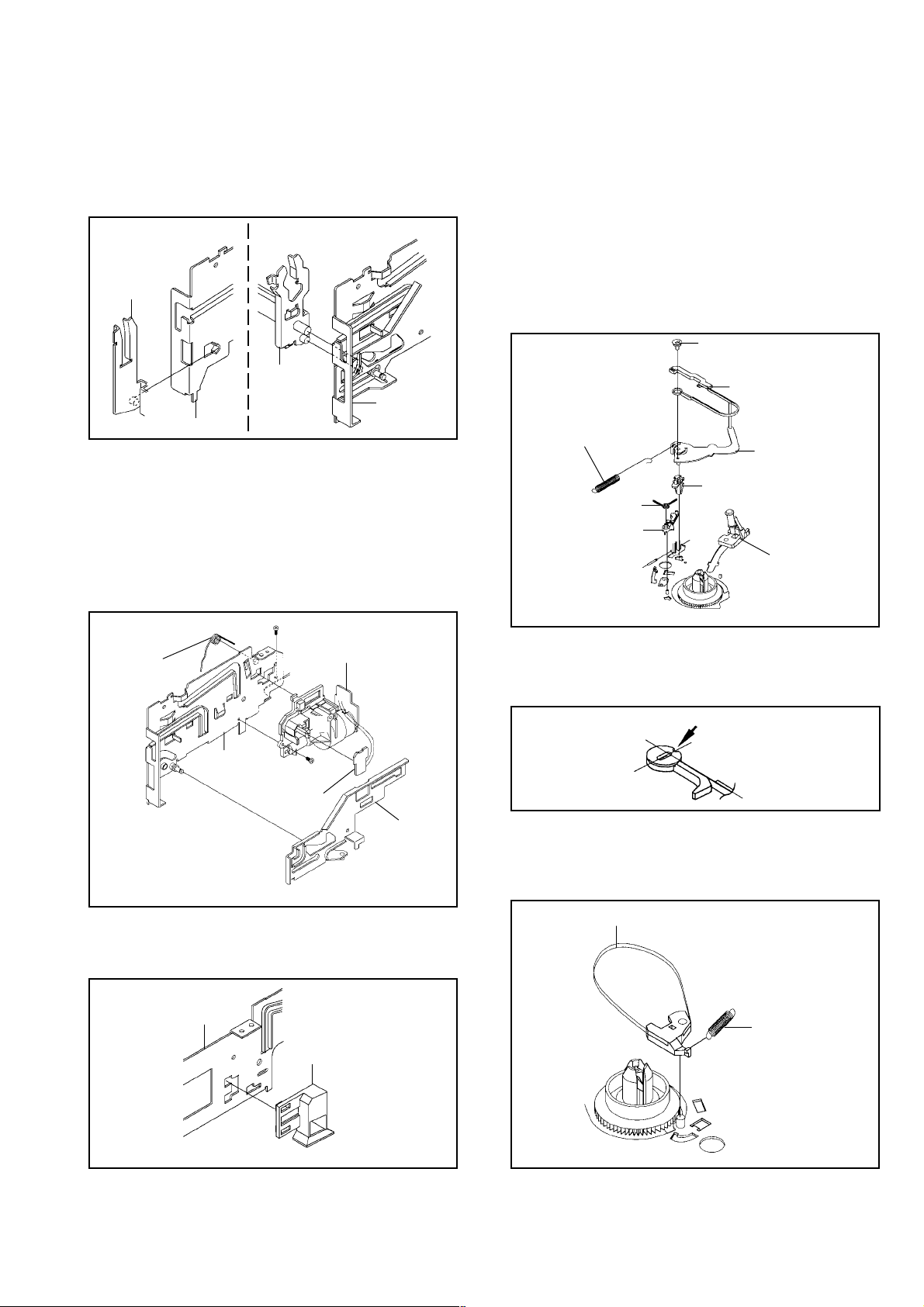
2-6: LINK ASS'Y (Refer to Fig. 2-6)
Set the Link Ass'y to the Eject position.
Remove the (A) side of the Link Ass'y first, then remove
the (B) side.
1.
2.
Main Chassis
(A)
Main Chassis
Link Ass'y
Fig. 2-6
2-7: LOADING MOTOR ASS'Y (Refer to Fig. 2-7)
Remove the Link Lever.
Remove the Dumper Spring.
Remove the 2 screws 1.
Unlock the support 2 and remove the Loading Motor
Ass'y.
Unlock the 2 supports 3 and remove the Deck PCB
(BOT).
1.
2.
3.
4.
5.
2-9: TENSION ASS'Y (Refer to Fig. 2-9-A)
Move the Inclined S Ass'y to the back side.
Remove the Tension Spring.
Unlock the support 1 and remove the Tension Arm
Ass'y.
Remove the Tension Adjust.
Unlock the 2 supports 2 and remove the Tension Band
Ass'y.
Unlock the support 3 and remove the Tension Holder.
Remove the SS Brake Spring.
Remove the SS Arm Brake.
1.
2.
3.
4.
5.
6.
7.
8.
1
2
1
Loading Motor Ass'y
Link Lever
Main Chassis
• Screw Torque: 5 ± 0.5kgf•cm
Fig. 2-7
2-8: SENSOR COVER L3 (Refer to Fig. 2-8)
Unlock the support 1 and remove the Sensor Cover L3.1.
Deck PCB
(BOT)
Link Ass'y
(B)
Dumper Spring
3
3
1
2
2
Tension Adjust
Tension Band Ass'y
Tension Spring
Tension Arm Ass'y
Tension Holder
Inclined S Ass'y
Fig. 2-9-A
SS Brake Spring
SS Arm Brake
NOTE
When you install the Tension Adjust, install as shown in
Fig. 2-9-B. (Refer to Fig. 2-9-B)
Fig. 2-9-B
2-10: T BRAKE ASS'Y (Refer to Fig. 2-10)
Remove the T Brake Spring.
Remove the T Brake Ass'y.
1.
2.
T Brake Ass'y
Fig. 2-10
Adjust the direction of the Marker to inside.
T Brake Spring
Main Chassis
Sensor Cover L3
1
Fig. 2-8
7
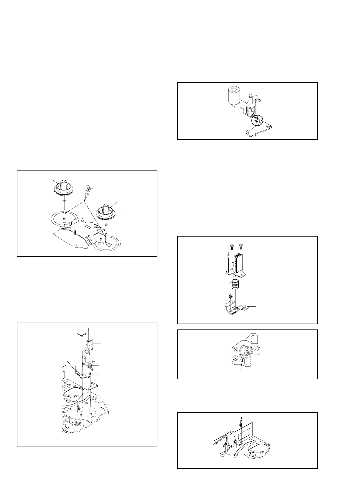
2-11: S REEL/T REEL (Refer to Fig. 2-11)
Remove the S Reel and T Reel.
1.
Remove the 2 Polyslider Washers 1.
2.
NOTE
Take care not to damage the gears of the S Reel and T
1.
Reel.
The Polyslider Washer may be remained on the back of
2.
the reel.
Take care not to damage the shaft.
3.
Do not touch the section "A" of S Reel and T Reel. (Use
4.
gloves.) (Refer to Fig. 2-11) Do not adhere the stains
on it.
When you install the reel, clean the shaft and oil it (FL
5.
OIL #6115). (If you do not oil, noise may be heard in FF/
REW mode.)
After installing the reel, adjust the height of the reel.
6.
(Refer to MECHANICAL ADJUSTMENT)
S Reel
(A)
1
T Reel
(A)
1
NOTE
Do not touch the Pinch Roller. (Use gloves.)
1.
When you install the Pinch Roller Block, install as shown
2.
in the circle of Fig. 2-12-B. (Refer to Fig. 2-12-B)
Fig. 2-12-B
2-13: A/C HEAD (Refer to Fig. 2-13-A)
1.
Remove the screw 1.
2.
Remove the A/C Head Base.
3.
Remove the 3 screws 2.
4.
Remove the A/C Head and A/C Head Spring.
NOTE
Do not touch the A/C Head. (Use gloves.)
1.
When you install the A/C Head Spring, install as shown
2.
in Fig. 2-13-B. (Refer to Fig. 2-13-B)
When you install the A/C Head, tighten the screw (1)
3.
first, then tighten the screw (2), finally tighten the screw
(3).
2-12: PINCH ROLLER BLOCK/P5-3 ARM ASS'Y
(Refer to Fig. 2-12-A)
Remove the P5 Spring.
1.
Remove the screw 1.
2.
Unlock the 2 supports 2 and remove the Cassette
3.
Opener.
Remove the Pinch Roller Block, Pinch Roller Arm
4.
Spring, Pinch Roller Lever Ass'y and P5-3 Arm Ass'y.
P5 Spring
P5-3 Arm Ass'y
1
2
Cassette Opener
2
Pinch Roller Block
Pinch Roller Arm Spring
Pinch Roller Lever Ass'y
Main Chassis
Fig. 2-11
(3)
(1)
2
2
(2)
1
• Screw Torque: 4 ± 0.5kgf•cm (Screw 1)
2
A/C Head
A/C Head Spring
A/C Head Base
Spring Position
2-14: FE HEAD (Refer to Fig. 2-14)
Remove the screw 1.
1.
Remove the FE Head.
2.
Fig. 2-13-A
Fig. 2-13-B
• Screw Torque: 5 ± 0.5kgf•cm
8
Fig. 2-12-A
FE Head
• Screw Torque: 4 ± 0.5kgf•cm
1
Fig. 2-14
1
2
E-Ring
Middle Gear
Main Cam
Pinch Roller Cam
Joint Gear
P5 Cam
Fig. 2-17-A
NOTE
When you install the Pinch Roller Cam, P5 Cam and Main
Cam, align each marker. (Refer to Fig. 2-17-B)
Pinch Roller Cam
P5 Cam
Main Cam
Marker
Check the hole of Main
Chassis can be seen.
Fig. 2-17-B
2-18: CLUTCH ASS'Y (Refer to Fig. 2-18)
Remove the Polyslider Washer 1.
Remove the Clutch Ass'y, Ring Spring and Coupling
Gear.
Unlock the 2 supports 2 and remove the Clutch Lever.
1.
2.
3.
2-16: CAPSTAN DD UNIT (Refer to Fig. 2-16)
Remove the Capstan Belt.
Remove the 3 screws 1.
Remove the Capstan DD Unit.
1.
2.
3.
• Screw Torque: 5 ± 0.5kgf•cm
Fig. 2-16
2-17: MIDDLE GEAR/MAIN CAM (Refer to Fig. 2-17-A)
Remove the Polyslider Washer 1, then remove the
Middle Gear.
Remove the E-Ring, then remove the Main Cam, P5
Cam and Pinch Roller Cam.
Remove the Polyslider Washer 2, then remove the
Joint Gear.
1.
2.
3.
Capstan DD Unit
Capstan Belt
1
1
1
Fig. 2-18
1
Clutch Ass'y
Ring Spring
Coupling Gear
Clutch Lever
2
2
2-15: AHC ASS'Y/CYLINDER UNIT ASS'Y
(Refer to Fig. 2-15)
Unlock the support 1 and remove the AHC Ass'y.
Remove the 3 screws 2.
Remove the Cylinder Unit Ass'y.
1.
2.
3.
When you install the Cylinder Unit Ass'y, tighten the
screws from (1) to (3) in order while pulling the Ass'y
toward the left front direction.
NOTE
1
AHC Ass'y
Cylinder Unit Ass'y
2
2
2
• Screw Torque: 3 ± 0.5kgf•cm
Fig. 2-15
(1)
(3)
(2)
9

2-19: LOADING GEAR S/T ASS'Y (Refer to Fig. 2-19-A)
Remove the E-Ring 1 and remove the Main Loading
1.
Gear.
Remove the Capstan Brake Spring.
2.
Slide the Main Rod and remove the Capstan Brake
3.
Ass'y.
Remove the Main Rod, Tension Lever, Clutch Actuator,
4.
Idler Arm Ass'y.
Remove the screw 2.
5.
Remove the LED Reflecter.
6.
Remove the Loading Arm S Ass'y and Loading Arm T
7.
Ass'y.
8.
Remove the Loading Gear S and Loading Gear T.
9.
Remove the Loading Gear Spring.
2. When you install the Clutch Actuator, install as shown in
the circle of Fig. 2-19-C. (Refer to Fig. 2-19-C)
Clutch Actuator
Fig. 2-19-C
Capstan Brake Spring
Main Rod
Idler Arm Ass'y
LED Reflecter
Clutch Actuator
• Screw Torque: 5 ± 0.5kgf•cm
Capstan Brake Ass'y
2
1
Main Loading Gear
Tension Lever
Loading Gear T
Loading Gear
Spring
Loading Arm T Ass'y
Loading Gear S
Loading Gear
Spring
Loading Arm S Ass'y
Fig. 2-19-A
NOTES
1. When you install the Loading Arm S Ass'y, Loading Arm
T Ass'y and Main Loading Gear, align each marker.
(Refer to Fig. 2-19-B)
2-20: INCLINED S/T ASS'Y (Refer to Fig. 2-20)
Unlock the support 1 and remove the P4 Cover.
1.
Remove the screw 2.
2.
Unlock the support 3 and remove the Loading Gear
3.
Holder.
Remove the Inclined S.
4.
Remove the Inclined T.
5.
Remove the 2 screws 4, then remove the Guide Roller.
6.
NOTE
Do not touch the roller of Guide Roller.
2
Loading Gear Holder
Guide Roller
4
Inclined S
3
Guide Roller
4
Inclined T
P4 Cover
1
10
Main Loading Gear
Marker
Loading Arm T Ass'y
Marker
Loading Arm S Ass'y
Fig. 2-19-B
• Screw Torque: 5 ± 0.2kgf•cm (Screw 2)
• Screw Torque: 0.7 ± 0.2kgf•cm (Screw 4)
Fig. 2-20

3. REMOVAL OF ANODE CAP
Read the following NOTED items before starting work.
After turning the power off there might still be a potential
voltage that is very dangerous. When removing the
Anode Cap, make sure to discharge the Anode Cap's
potential voltage.
Do not use pliers to loosen or tighten the Anode Cap
terminal, this may cause the spring to be damaged.
*
*
REMOVAL
1. Follow the steps as follows to discharge the Anode Cap.
(Refer to Fig. 3-1.)
Connect one end of an Alligator Clip to the metal part of a
flat-blade screwdriver and the other end to ground.
While holding the plastic part of the insulated Screwdriver,
touch the support of the Anode with the tip of the
Screwdriver.
A cracking noise will be heard as the voltage is discharged.
Flip up the sides of the Rubber Cap in the direction of
the arrow and remove one side of the support.
(Refer to Fig. 3-2.)
2.
GND on the CRT
Screwdriver
Alligator Clip
Support
CRT
GND on the CRT
Rubber Cap
CRT
Support
Fig. 3-1
Fig. 3-2
3. After one side is removed, pull in the opposite direction
to remove the other.
NOTE
INSTALLATION
1. Clean the spot where the cap was located with a small
amount of alcohol. (Refer to Fig. 3-3.)
NOTE
Confirm that there is no dirt, dust, etc. at the spot where
the cap was located.
2.3.Arrange the wire of the Anode Cap and make sure the
wire is not twisted.
Turn over the Rubber Cap. (Refer to Fig. 3-4.)
Fig. 3-4
4. Insert one end of the Anode Support into the anode
button, then the other as shown in Fig. 3-5.
CRT
Support
Fig. 3-5
5.6.Confirm that the Support is securely connected.
Put on the Rubber Cap without moving any parts.
Location of Anode Cap
Fig. 3-3
Take care not to damage the Rubber Cap.
11

A
A/C
ACC
AE
AFC
AFT
AFT DET
AGC
AMP
ANT
A.PB
APC
ASS'Y
AT
AUTO
A/V
B
BGP
BOT
BPF
BRAKE SOL
BUFF
B/W
C
C
CASE
CAP
CARR
CH
CLK
CLOCK (SY-SE)
COMB
CONV
CPM
CTL
CYL
CYL-M
CYL SENS
D
DATA (SY-CE)
dB
DC
DD Unit
DEMOD
DET
DEV
E
E
EF
EMPH
ENC
ENV
EOT
EQ
EXT
F
F
FBC
FE
FF
FG
FL SW
FM
FSC
FWD
G
GEN
GND
H
H.P.F
KEY TO ABBREVIA TIONS
:
Audio/Control
:
Automatic Color Control
:
Audio Erase
:
Automatic Frequency Control
:
Automatic Fine Tuning
:
Automatic Fine Tuning Detect
:
Automatic Gain Control
:
Amplifier
:
Antenna
:
Audio Playback
:
Automatic Phase Control
:
Assembly
:
All Time
:
Automatic
:
Audio/Video
:
Burst Gate Pulse
:
Beginning of Tape
:
Bandpass Filter
:
Brake Solenoid
:
Buffer
:
Black and White
:
Capacitance, Collector
:
Cassette
:
Capstan
:
Carrier
:
Channel
:
Clock
:
Clock (Syscon to Servo)
:
Combination, Comb Filter
:
Converter
:
Capstan Motor
:
Control
:
Cylinder
:
Cylinder-Motor
:
Cylinder-Sensor
:
Data (Syscon to Servo)
:
Decibel
:
Direct Current
:
Direct Drive Motor Unit
:
Demodulator
:
Detector
:
Deviation
:
Emitter
:
Emitter Follower
:
Emphasis
:
Encoder
:
Envelope
:
End of Tape
:
Equalizer
:
External
:
Fuse
:
Feed Back Clamp
:
Full Erase
:
Fast Forward, Flipflop
:
Frequency Generator
:
Front Loading Switch
:
Frequency Modulation
:
Frequency Sub Carrier
:
Forward
:
Generator
:
Ground
:
High Pass Filter
H.SW
Hz
IC
I
IF
IND
INV
KIL
K
L
L
LED
LIMIT AMP
LM, LDM
LP
L.P.F
LUMI.
M
M
MAX
MINI
MIX
MM
MOD
MPX
MS SW
NC
N
NR
OSC
O
OPE
PB
P
PB CTL
PB-C
PB-Y
PCB
P. CON
PD
PG
P-P
R
R
REC
REC-C
REC-Y
REEL BRK
REEL S
REF
REG
REW
REV, RVS
RF
RMC
RY
S
S. CLK
S. COM
S. DATA
SEG
SEL
SENS
SER
SI
SIF
SO
SOL
SP
STB
SW
:
Head Switch
:
Hertz
:
Integrated Circuit
:
Intermediate Frequency
:
Indicator
:
Inverter
:
Killer
:
Left
:
Light Emitting Diode
:
Limiter Amplifier
:
Loading Motor
:
Long Play
:
Low Pass Filter
:
Luminance
:
Motor
:
Maximum
:
Minimum
:
Mixer, mixing
:
Monostable Multivibrator
:
Modulator, Modulation
:
Multiplexer, Multiplex
:
Mecha State Switch
:
Non Connection
:
Noise Reduction
:
Oscillator
:
Operation
:
Playback
:
Playback Control
:
Playback-Chrominance
:
Playback-Luminance
:
Printed Circuit Board
:
Power Control
:
Phase Detector
:
Pulse Generator
:
Peak-to Peak
:
Right
:
Recording
:
Recording-Chrominance
:
Recording-Luminance
:
Reel Brake
:
Reel Sensor
:
Reference
:
Regulated, Regulator
:
Rewind
:
Reverse
:
Radio Frequency
:
Remote Control
:
Relay
:
Serial Clock
:
Sensor Common
:
Serial Data
:
Segment
:
Select, Selector
:
Sensor
:
Search Mode
:
Serial Input
:
Sound Intermediate Frequency
:
Serial Output
:
Solenoid
:
Standard Play
:
Serial Strobe
:
Switch
12

S
SYNC
SYNC SEP
T
TR
TRAC
TRICK PB
TP
U
UNREG
V
V
VCO
VIF
VP
V.PB
VR
V.REC
VSF
VSR
VSS
V-SYNC
VT
X
X'TAL
Y
Y/C
:
Synchronization
:
Sync Separator, Separation
:
Transistor
:
Tracking
:
Trick Playback
:
Test Point
:
Unregulated
:
Volt
:
Voltage Controlled Oscillator
:
Video Intermediate Frequency
:
Vertical Pulse, Voltage Display
:
Video Playback
:
Variable Resistor
:
Video Recording
:
Visual Search Fast Forward
:
Visual Search Rewind
:
Voltage Super Source
:
Vertical-Synchronization
:
Voltage Tuning
:
Crystal
:
Luminance/Chrominance
13

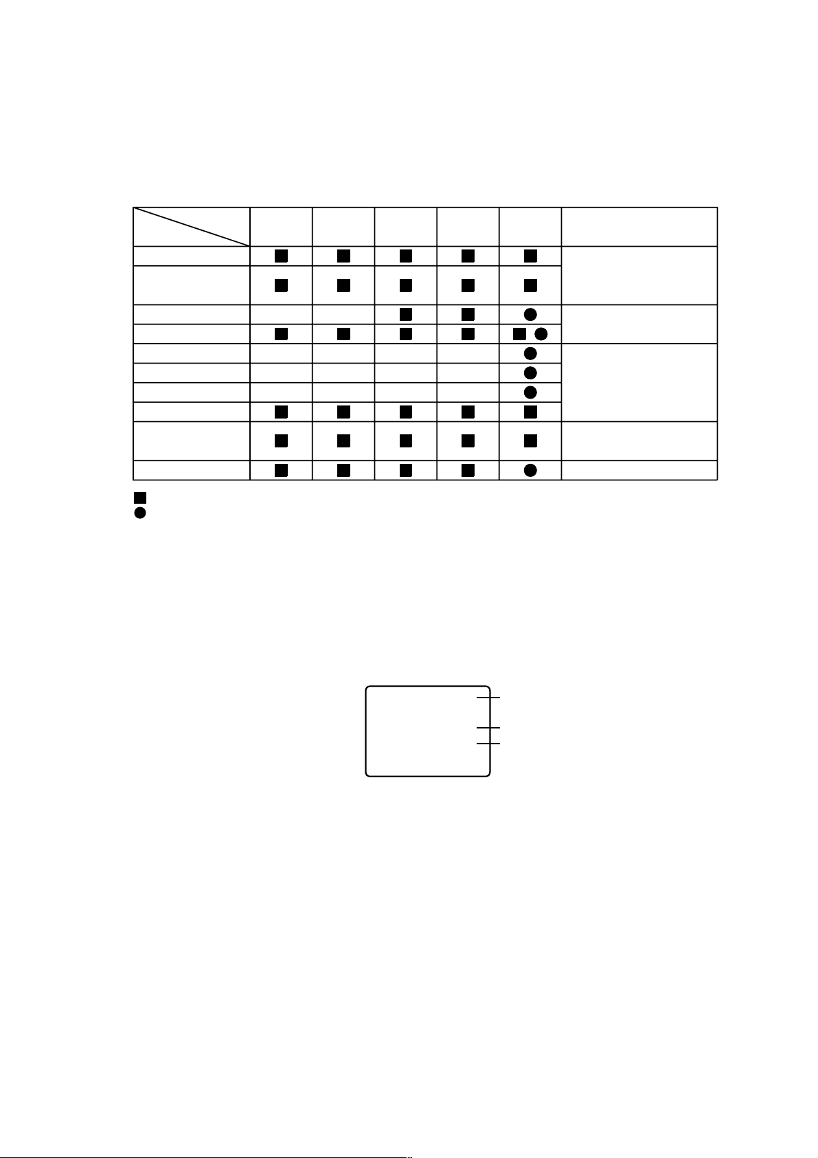
SERVICE MODE LIST
This unit provided with the following SERVICE MODES so you can repair, examine and adjust easily.
To enter SERVICE MODE, unplug AC cord till lost actual clock time. Then press and hold Vol (-) button of main unit and
remocon key simultaneously.
The both pressing of set key and remote control key will not be possible if clock has been set. To reset clock, either unplug
AC cord and allow at least 5 seconds before Power On.
Set Key Remocon Key Operations
VOL. (-) MIN
VOL. (-) MIN 1
VOL. (-) MIN
VOL. (-) MIN
VOL. (-) MIN 4
VOL. (-) MIN
VOL. (-) MIN
0
2
3
5
6
Releasing of V-CHIP PASSWORD.
Initialization of the factory.
NOTE: Do not use this for the normal servicing.
Horizontal position adjustment of OSD.
NOTE: Also can be adjusted by using the Adjustment MENU.
Refer to the "ELECTRICAL ADJUSTMENT" (OSD HORIZONTAL).
Adjust the SWITCHING POINT automatically.
Refer to the "ELECTRICAL ADJUSTMENT" (PG SHIFTER).
Adjust the SWITCHING POINT manually.
Refer to the "ELECTRICAL ADJUSTMENT" (PG SHIFTER).
Adjusting of the Tracking to the center position.
NOTE: Also can be adjusted by pressing the ATR button for more than 2 seconds
during PLAY.
POWER ON total hours and PLAY/REC total hours are displayed on the screen.
Refer to the "PREVENTIVE CHECKS AND SERVICE INTERVALS" (CONFIRMATION
OF USING HOURS).
Can be checked of the INITIAL DATA of MEMORY IC.
Refer to the "NOTE FOR THE REPLACING OF MEMORY IC".
VOL. (-) MIN 8
VOL. (-) MIN 9
Method Operations
Press the ATR button on the
remote control for more than
2 seconds during PLAY.
Make the short circuit between
the test point of SERVICE and
the GND.
14
Writing of EEPROM initial data.
NOTE: Do not use this for the normal servicing.
Display of the Adjustment MENU on the screen.
Refer to the "ELECTRICAL ADJUSTMENT" (On-Screen Display Adjustment).
Adjusting of the Tracking to the center position.
Refer to the "MECHANICAL ADJUSTMENT" (GUIDE ROLLER) and "ELECTRICAL
ADJUSTMENT" (SWITCHING POINT).
The EOT/BOT/Reel sensor do not work at this moment.
Refer to the "PREPARATION FOR SERVICING"
PREVENTIVE CHECKS AND SERVICE INTERVALS
The following standard table depends on environmental conditions and usage. Unless maintenance is properly
carried out, the following service intervals may be quite shortened as harmful effects may be had on other parts.
Also, long term storage or misuse may cause transformation and aging of rubber parts.
Time
Parts Name
Audio Control Head
Full Erase Head
(Recorder only)
Capstan Belt
Pinch Roller
Capstan DD Unit
Loading Motor
Tension Band
Capstan Shaft
Tape Running
Guide Post
Cylinder Unit
: Clean
: Replace
500
hours
1,000
hours
1,500
hours
2,000
hours
3,000
hours
Notes
Clean those parts in
contact with the tape.
Clean the rubber, and parts
which the rubber touches.
Replace when rolling
becomes abnormal.
Clean the Head
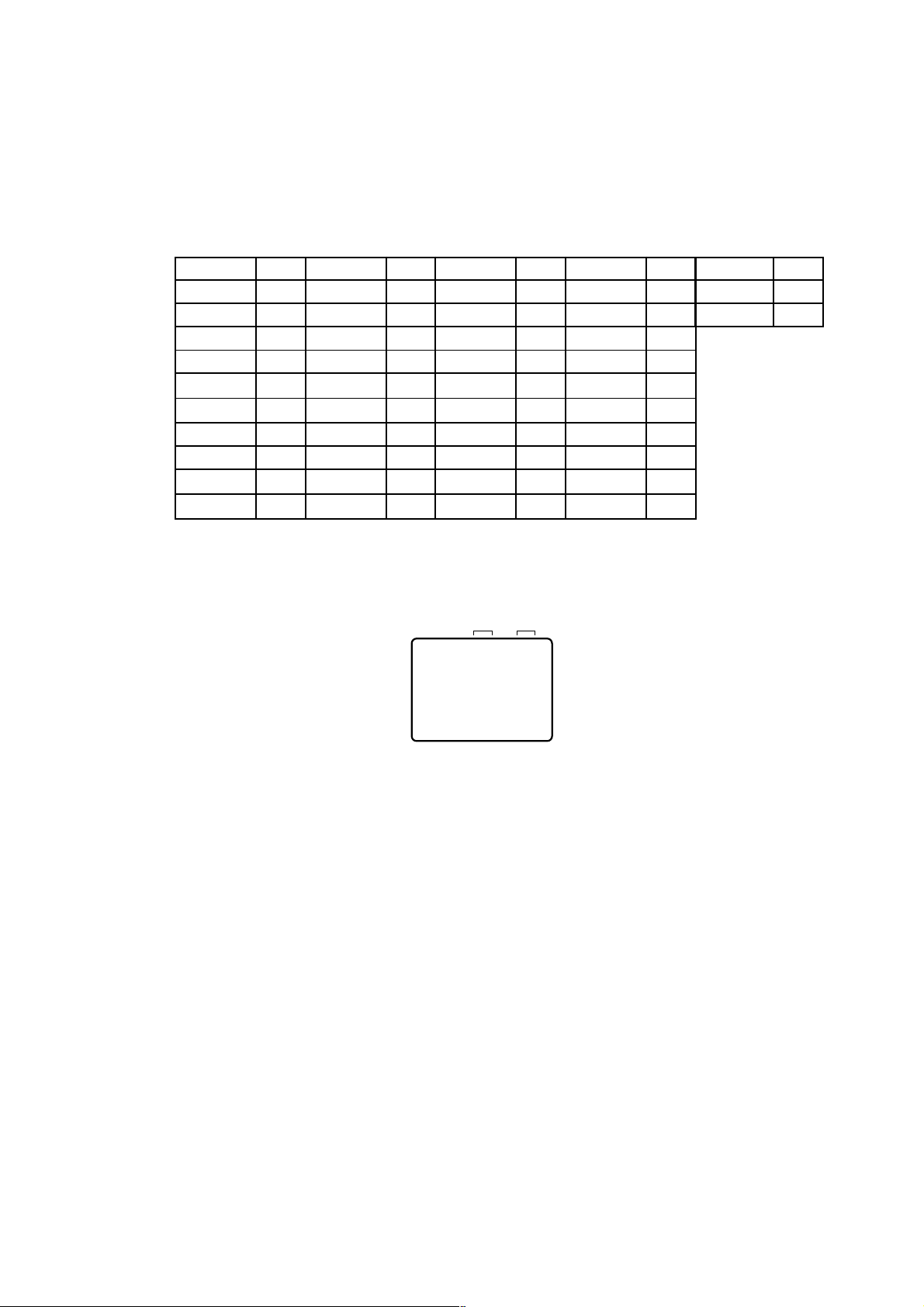
CONFIRMATION OF USING HOURS
POWER ON total hours and PLAY/REC total hours can be checked on the screen.
Total hours are displayed in 16 system of notation.
NOTE: The confirmation of using hours will not be possible if clock has been set. To reset clock, either unplug
AC cord and allow at least 5 seconds before Power On.
1.
Set the VOLUME to minimum.
2.
While holding down VOLUME button on front cabinet, press key 6 on remote control simultaneously.
3.
After the confirmation of using hours, turn off the power.
INIT 00 83
POWER ON
PLAY/REC
(16 x 16 x 16 x thousands digit value) + (16 x 16 x hundreds digit value) + (16 x tens digit value) + (ones digit value)
0010
0003
Initial setting content of MEMORY IC.
POWER ON total hours.
PLAY/REC total hours.
15
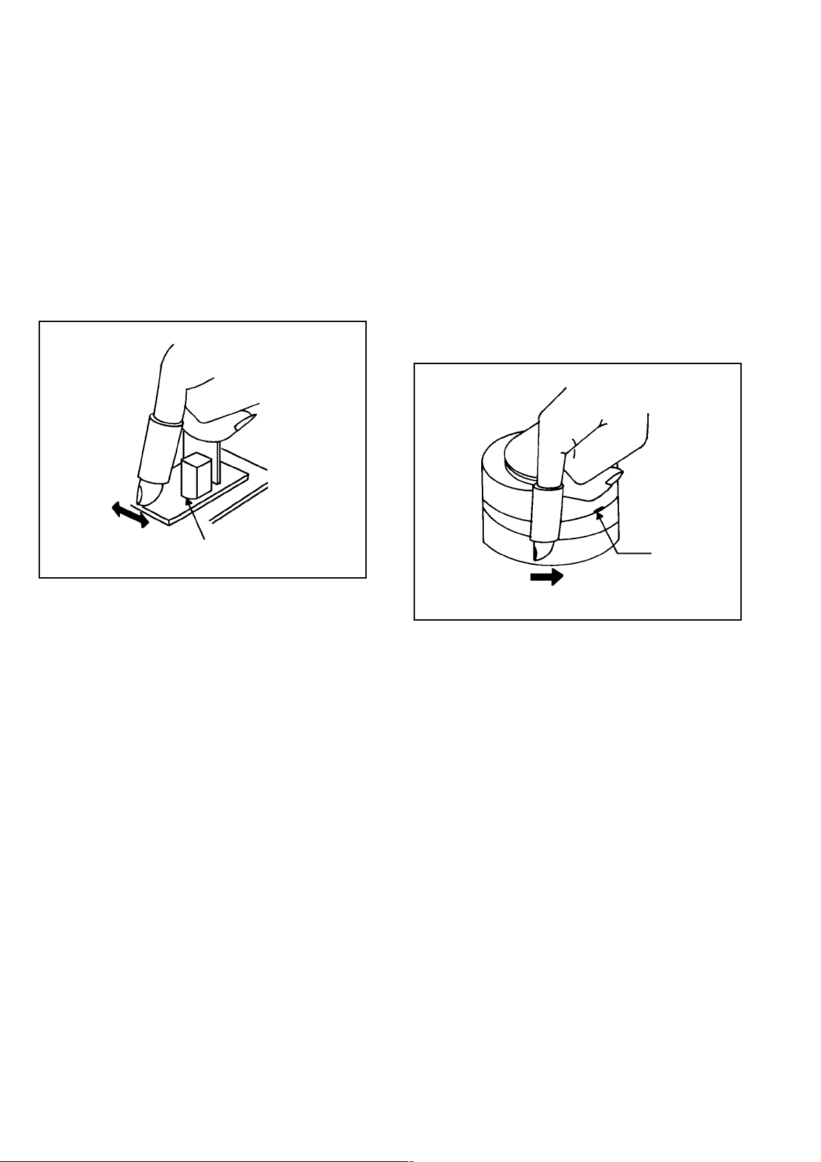
CLEANING
NOTE
After cleaning the heads with isopropyl alcohol, do not
run a tape until the heads dry completely. If the heads
are not completely dry and alcohol gets on the tape,
damage may occur.
1. AUDIO CONTROL HEAD
Wrap a piece of chamois around your finger. Dip it in
isopropyl alcohol and clean the audio control head by
wiping it horizontally. Clean the full erase head in the
same manner. (Refer to the figure below.)
2. TAPE RUNNING SYSTEM
When cleaning the tape transport system, use the
gauze moistened with isopropyl alcohol.
3. CYLINDER
Wrap a piece of chamois around your finger. Dip it in
isopropyl alcohol. Hold it to the cylinder head softly.
Turn the cylinder head counterclockwise to clean it (in
the direction of the arrow). (Refer to the figure below.)
NOTE
Do not exert force against the cylinder head. Do not move
the chamois upward or downward on the head.
Use the chamois one by one.
Audio Control Head
Cylinder Head
16
Initial Data setting will not be possible if clock has been set. To reset clock, either unplug AC cord and allow
at least 5 seconds before Power On.
NOTE FOR THE REPLACING OF MEMORY IC
If a service repair is undertaken where it has been required to change the MEMORY IC, the following steps should be taken to
ensure correct data settings while making reference to TABLE 1.
NOTE:
Table 1
3.
4.
5.
6.
7.
8.
The unit will now have the correct DATA for the new MEMORY IC.
1.
2.
Fig. 1
ADDRESS is now selected and should "blink". Using the SET + or - keys on the remote, step through the ADDRESS until
required ADDRESS to be changed is reached.
Press ENTER to select DATA. When DATA is selected, it will "blink".
Again, step through the DATA using SET + or - until required DATA value has been selected.
Pressing ENTER will take you back to ADDRESS for further selection if necessary.
Repeat steps 3 to 6 until all data has been checked.
When satisfied correct DATA has been entered, turn POWER off (return to STANDBY MODE) to finish DATA input.
Enter DATA SET mode by setting VOLUME to minimum.
While holding down VOLUME button on front cabinet, press key 6 on remote control simultaneously.
ADDRESS and DATA should appear as FIG 1.
INIT 00 83
0010
0003
POWER ON
PLAY/REC
ADDRESS DATA
00
01
02
04
05
06
07
08
09
88 0A DC 14 27 1E 0E 28 01
ADDRESS DATA ADDRESS DATA ADDRESS DATA ADDRESS DATA ADDRESS DATA
79 0B 02 15 00 1F 03 29 35
A2 0C 63 16 90 20 BA
03 47 0D 0D 17 05 21 05
C3 0E 17 18 80 22 79
23 0F 0A 19 89 23 05
34 10 8C 1A A9 24 3E
1B 11 68 1B 22 25 2A
59 12 5C 1C 05 26 39
B2 13 53 1D 39 27 00
17
SERVICE ADJUSTMENT
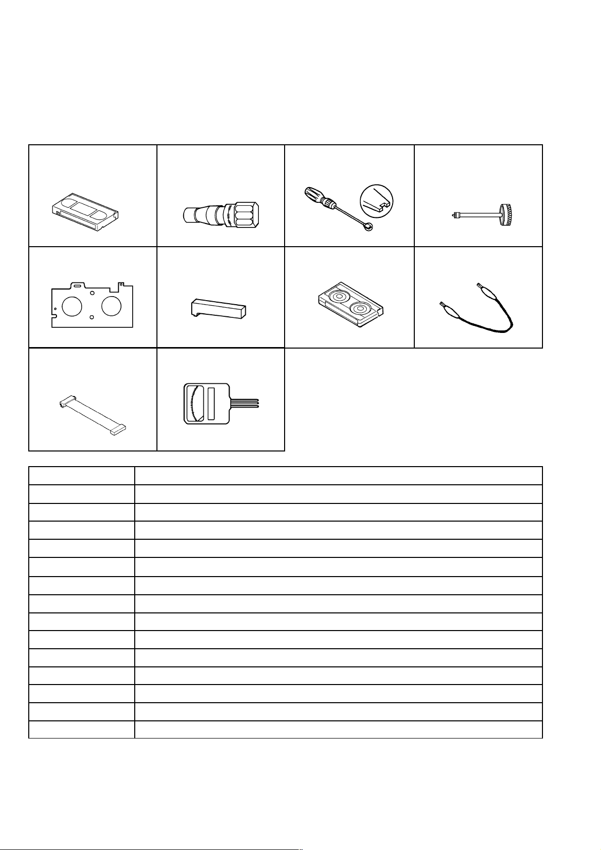
SERVICING FIXTURES AND TOOLS
(For 4 heads model)
VHS Alignment Tape
MHP
Master Plane Reel Disk Height
X-JG162A Cable (8 Pins)
X-JG162F Cable (13 Pins)
X-JG162Y Cable (5 Pins)
Torque Gauge PTU94002 Roller Driver X-JG153 X Value Adjustment
Adjustment Jig
Tentelometer
Screwdriver
Torque Tape Short Jumper
Part No.
MHP
MHP
PTU94002 Guide Roller Adjustment
X-JG153 X Value Adjustment
Short Jumper Used to connect the TP1001 and GROUND
X-JG162A/X-JG162F Used to connect the Syscon PCB and Main PCB
X-JG162Y Used to connect the Syscon PCB and CRT PCB
Monoscope (For 4 heads model)
Color Bar, 1KHz (For 4 heads model)
Hi-Fi Audio (For 4 heads Hi-Fi model)
X Value Adjustment
VSR Torque, Brake Torque (S Reel/T Reel Ass'y)
Brake Torque (T Reel Ass'y)
VSR Torque, Brake Torque (S Reel)
Reel Disk Height Adjustment
Playback Torque, Back Tension Torque During Playback
Remarks
18

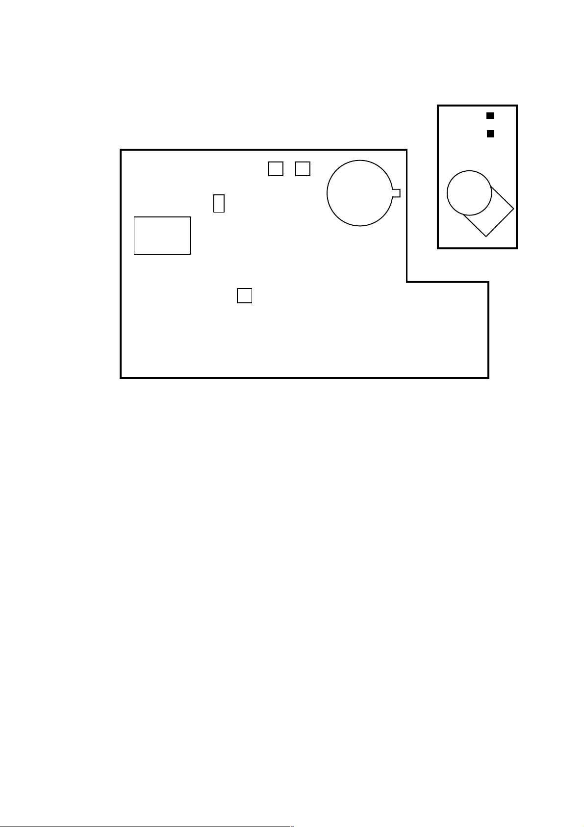
PREP ARATION FOR SERVICING
Basic Servicing Position (In case of needing to check on all blocks)
1.
2.
3.
4.
5.
6.
Unplug the connector CP502, CP4201 and CP4202, then remove the TV/VCR Block from the set.
Unplug the connector CP810, CP820 and CP805, then remove the Main PCB from the VCR Block.
Connect as shown in the below figure using the Service Fixture.
• Connect the Syscon PCB to the Main PCB with the cable X-JG162A and X-JG162F.
• Connect the Syscon PCB to the CRT PCB with the cable X-JG162Y.
Remove the Operation PCB from the set, then connect it with the Syscon PCB.
If necessary, connect CP4202 (Front A/V Jack Input Terminal)
Short circuit between TP1001 and Ground with the Short Jumper.
The EOT, BOT and Reel Sensor do not work at this moment.
At that time, the STOP/EJECT button is available to insert and eject the Cassette Tape.
CP805
CD810
Front Cabinet
CRT PCB
Syscon PCB
CP4201
CD757
CP820
Main PCB
CP810
X-JG162A
CD601
CD850
Operation PCB
Short Jumper
To Ground
X-JG162F
X-JG162Y
TP1001
19
MECHANICAL ADJUSTMENTS
1. CONFIRMATION AND ADJUSTMENT
Read the following NOTES before starting work.
••Place an object which weighs between 450g~500g on
the Cassette Tape to keep it steady when you want to
make the tape run without the Cassette Holder. (Do not
place an object which weighs over 500g.)
When you activate the deck without the Cassette
Holder, short circuit between TP1001 and GND. (Refer
to ELECTRICAL ADJUSTMENT PARTS LOCATION
GUIDE) In this condition the BOT/EOT/Reel Sensor will
not function.
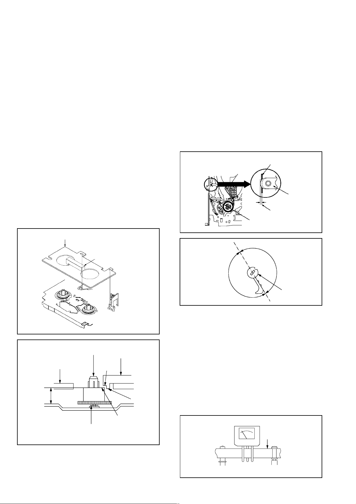
CONFIRMATION AND ADJUSTMENT OF REEL
1-1:
DISK HEIGHT
1.
Turn on the power and set to the STOP mode.
2.
Set the master plane and reel disk height adjustment jig
on the mechanism framework, taking care not to scratch
the drum, as shown in Fig. 1-1-A.
Confirm that "A" of the reel disk is lower than "B" of the
3.
reel disk height adjustment jig , and is higher than "C". If
it is not enough height, adjust to 10(+0.2, -0) mm with
the height adjustment washer.
4.
Adjust the other reel in the same way.
Master Plane
1-2: CONFIRMATION AND ADJUSTMENT OF TENSION
POST POSITION
1.
Set to the PLAY mode.
2.
Adjust the Tension Adjust until the edge of the Tension
Arm is positioning within 0.5mm range from the
standard line center of Main Chassis.
After this adjustment, confirm that the cut position is
located in "A" area as shown in Fig. 1-2-B. If it is
located in "B" area, adjust again.
3.
While turning the S Reel clockwise, confirm that the
edge of the Tension Arm is located in the position
described above.
Standard line of Main Chassis
Tension Arm
0.5mm (Adjusting range)
Standard line center of Main Chassis
Tension Adjust
Fig. 1-2-A
10(+0.2, -0)mm
Master Plane
Reel Disk Height Adjustment Jig
Reel Disk
Height Adjustment
Washer
2.6x4.7xT0.13
2.6X4.7xT0.25
Reel Disk Height
Adjustment Jig
(B)
(A)
Fig. 1-1-A
(C)
Fig. 1-1-B
(A)
Cut Position
(B)
Tension Adjust
Fig. 1-2-B
1-3: CONFIRMATION OF PLAYBACK TORQUE AND
BACK TENSION TORQUE DURING PLAYBACK
Load a video tape (T-120) recorded in standard speed
1.
mode. Set the unit to the PLAY mode.
Install the tentelometer as shown in Fig. 1-3. Confirm that
2.
the meter indicates 20 ± 2gf in the beginning of playback.
• USING A CASSETTE TYPE TORQUE TAPE
1.
After confirmation and adjustment of Tension Post
position (Refer to item 1-2), load the cassette type
torque tape and set to the PLAY mode.
2.
Confirm that the right meter of the torque tape indicates
60~110gf•cm during playback in SP mode.
3.
Confirm that the left meter of the torque tape indicates
25~40gf•cm during playback in SP mode.
Tentelometer
Video Tape
20
P1 Post
Guide Roller
Fig. 1-3

1-4: CONFIRMATION OF VSR TORQUE
Operate within 4~5 seconds after the reel disk begins to
turn.
Install the Torque Gauge on the S Reel. Set to the Rewind
mode. (Refer to Fig.1-4)
Then, confirm that it indicates 120~180gf•cm.
1.
2.
3.
NOTE
Install the Torque Gauge on the reel disk firmly. Press the
REW button to turn the reel disk.
1-5: CONFIRMATION OF REEL BRAKE TORQUE
(S Reel Brake) (Refer to Fig. 1-4)
Set to the STOP mode.
Move the Idler Ass'y from the S Reel.
Install the Torque Gauge on the S Reel. Turn the Torque
Gauge clockwise.
Then, confirm that it indicates 60~100gf•cm.
1.
2.
3.
4.
2. CONFIRMATION AND ADJUSTMENT
OF TAPE RUNNING MECHANISM
Tape Running Mechanism is adjusted precisely at the
factory. Adjustment is not necessary as usual. When you
replace the parts of the tape running mechanism because
of long term usage or failure, the confirmation and
adjustment are necessary.
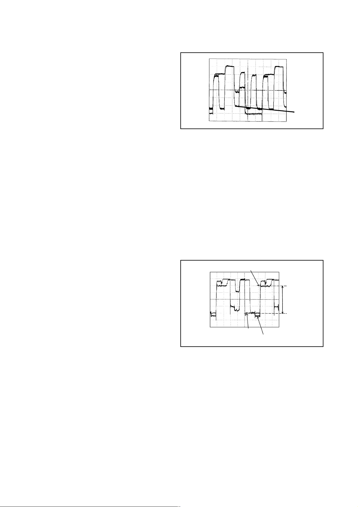
2-1: GUIDE ROLLER
Playback the Alignment Tape (MHP).
Connect CH-1 of the oscilloscope to TP4001 (Envelope)
and CH-2 to TP1002 (SW Pulse).
Press and hold the TRACKING-AUTO button on the
remote control more than 2 seconds to set tracking to
center.
Trigger with SW Pulse and observe the envelope. (Refer
to Fig. 2-1-A)
When observing the envelope, adjust the Roller Driver
(PTU94002) slightly until the envelope will be flat.
Even if you press the Tracking Button, adjust so that
flatness is not moved so much.
Adjust so that the A : B ratio is better than 3 : 2 as shown
in Fig. 2-1-B, even if you press the Tracking Button to
move the envelope (The envelope waveform will begin to
decrease when you press the Tracking Button).
Adjust the Switching Point during playback.
(Refer to the ELECTRICAL ADJUSTMENTS)
1.
2.
3.
4.
5.
6.
7.
NOTE
After adjustment, confirm and adjust A/C head.
(Refer to item 2-2)
CH-2
SW Pulse (TP1002)
CH-1
Track
CH-2
Track
CH-1
Envelope
(TP4001)
(T Reel Brake) (Refer to Fig. 1-4)
Set to the STOP mode.
Move the Idler Ass'y from the T Reel Ass'y.
Install the Torque Gauge on the T reel. Turn the Torque
Gauge counterclockwise.
Then, confirm that it indicates 45~70gf•cm.
1.
2.
3.
4.
NOTE
If the torque is out of the range, replace the following
parts.
Check item
1-4
1-5
Replacement Part
Idler Ass'y/Clutch Ass'y
T Brake Spring/Tension Spring
Fig. 1-4
T Reel
S Reel
Torque Gauge
Torque Gauge
Fig. 2-1-A
Max
A : B = 3 : 2
A
Entrance Exit
Max
B
Fig. 2-1-B
21

CONFIRMATION AND ADJUSTMENT OF AUDIO/
CONTROL HEAD
When the Tape Running Mechanism does not work well,
adjust the following items.
1.
Playback the Alignment Tape (MHP).
2.
Confirm that the reflected picture of stamp mark is
appeared on the tape prior to P4 Post as shown in Fig.
2-2-A.
When the reflected picture is distorted, turn the screw
a)
1 clockwise until the distortion is disappeared.
When the reflected picture is not distorted, turn the
b)
screw 1 counterclockwise until little distortion is
appeared, then adjust the a).
3.
Turn the screw 2 to set the audio level to maximum.
4.
Confirm that the bottom of the Audio/ Control Head and
the bottom of the tape is shown in Fig. 2-2-C.
When the height is not correct, turn the screw 3 to
c)
adjust the height. Then, adjust the 1~3 again.
Audio/Control Head
Reflected picture of
Stamp Mark
P4 Post
Stamp Mark
Audio/Control Head
Fig. 2-2-A
2-3:2-2:
TAPE RUNNING ADJUSTMENT
(X VALUE ADJUSTMENT)
Confirm and adjust the height of the Reel Disk.
1.
(Refer to item 1-1)
2.
Confirm and adjust the position of the Tension Post.
(Refer to item 1-2)
3.
Adjust the Guide Roller. (Refer to item 2-1)
4.
Confirm and adjust the Audio/Control Head.
(Refer to item 2-2)
5.
Connect CH-1 of the oscilloscope to TP4001, CH-2 to
TP1002 and CH-3 to HOT side of Audio Out Jack.
6.
Playback the Alignment Tape (MHP).
7.
Press and hold the TRACKING-AUTO button on the
remote control more than 2 seconds to set tracking to
center.
8.
Set the X Value adjustment driver (X-JG153) to the 4 of
Fig. 2-2-B. Adjust X value so that the envelope waveform
output becomes maximum.
2-4: CONFIRM HI-FI AUDIO
Connect CH-1 of the oscilloscope to TP4001, CH-2 to
1.
TP1002 and CH-3 to the Hi-Fi Audio Out Jack.
Playback the VHS Alignment Tape. (Refer to SERVICING
2.
FIXTURE AND TOOLS)
Press and hold the Tracking-Auto button on the remote
3.
control more than 2 seconds to set tracking to center.
Press the Tracking Up button and count number of steps
4.
which the audio output is changed from Hi-Fi to MONO.
Press the Tracking Down button and count number of
5.
steps which the audio output is changed from Hi-Fi to
MONO.
6.
Confirm that the difference between these counted steps
number in the above items are within 2 steps. If the
difference are more than 3 steps, do Tape Running
Adjustment again. (Refer to item 2-3)
3
2
Audio/Control Head
Tape
1
4
Fig. 2-2-B
0.25±0.05mm
Fig. 2-2-C
22
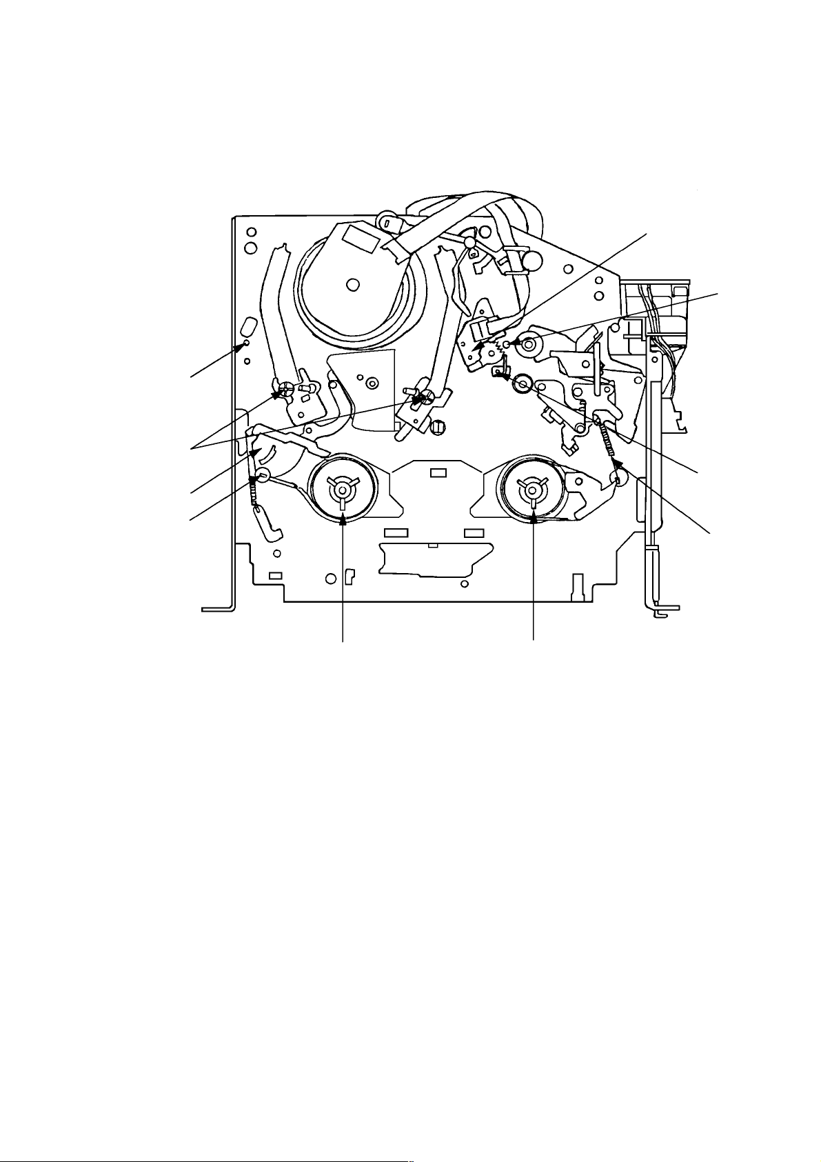
3. MECHANISM ADJUSTMENT PARTS LOCATION GUIDE
4
3
2
5
6
7
1
10
1. Tension Adjust
2. Tension Arm
3. Guide Roller
4. P1 Post
5. Audio/Control Head
6.
X value adjustment driver hole
7.
P4 Post
8.
T Brake Spring
9.
T Reel
10.
S Reel
9
8
23
1. ADJUSTMENT PROCEDURE
Read and perform these adjustments when repairing the
circuits or replacing electrical parts or PCB assemblies.
CAUTION
•
Use an isolation transformer when performing any
service on this chassis.
•
Before removing the anode cap, discharge electricity
because it contains high voltage.
•
When removing a PCB or related component, after
unfastening or changing a wire, be sure to put the wire
back in its original position.
Inferior silicon grease can damage IC's and transistors.
•
When replacing IC's and transistors, use only specified
silicon grease.
Remove all old silicon before applying new silicon.
On-Screen Display Adjustment
1.2.Unplug the AC plug for more than 5 seconds to set the
clock to the non-setting state. Then, set the volume
level to minimum.
Press the VOL. DOWN button on the set and the
channel button (9) on the remote control
simultaneously to display adjustment mode on the
screen as shown in Fig. 1-1.
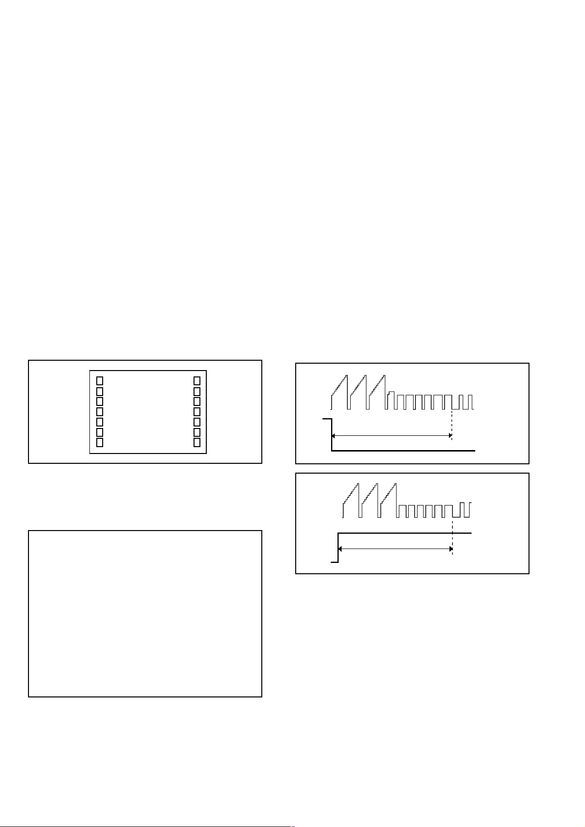
2. BASIC ADJUSTMENTS
(VCR SECTION)
2-1: PG SHIFTER
1.
Connect CH-1 on the oscilloscope to TP1002 and CH-2
to TP4201.
2.
Playback the alignment tape.
3.
Press and hold the Tracking-Auto button on the remote
control more than 2 seconds to set tracking to center.
4.
Press the VOL. DOWN button on the set and the
channel button (3) on the remote control simultaneously
until the indicator REC disappears. If the indicator REC
disappears, adjustment is completed.
(If the above adjustments doesn't work well:)
5.
Press the VOL. DOWN button on the set and the
channel button (3) on the remote control simultaneously
until the indicator REC disappears.
6.
When the REC indicator is blinking, press both VOL.
DOWN button on the set and the channel button (4) on
the remote control simultaneously and adjust the
Tracking +/- button until the arising to the down of Head
Switching Pulse becomes 6.5 ± 0.5H.
(Refer to Fig. 2-1-A, B)
7.
Press the Tracking Auto button.
TV
00 OSD 15
Use the Channel UP/DOWN button or Channel button
3.
(0-9) on the remote control to select the options shown
in Fig. 1-2.
Press the MENU button on the remote control to end
4.
the adjustments.
FUNCTION
NO.
OSD H
00
CUT OFF
01
RF DELAY
02
VIF VCO
03
H VCO
04
H PHASE
05
V SIZE
06
V SHIFT
07
R DRIVE
08
B DRIVE
09
R CUT OFF
10
G CUT OFF
11
B CUT OFF
12
FUNCTION
NO.
BRIGHTNESS
13
CONTRAST
14
COLOR
15
TINT
16
SHARPNESS
17
FM LEVEL
18
LEVEL
19
SEPARATION 1
20
SEPARATION 2
21
TEST MONO
22
TEST STEREO
23
X-RAY TEST
24
Fig. 1-1
Fig. 1-2
CH-2
6.5H
CH-1
Fig. 2-1-A
CH-2
CH-1
6.5H
Fig. 2-1-B
2-2: VCO FREERUN
1.
Place the set with Aging Test for more than 10 minutes.
2.
Connect the digital voltmeter between the pin 7 of
CP602 and the pin 1 (GND) of CP602.
3.
Activate the adjustment mode display of Fig. 1-1 and
press the channel button (03) on the remote control to
select "VIF VCO".
4.
Press the VOL. UP/DOWN button on the remote control
until the digital voltmeter is 2.5V.
24
2-3: RF AGC
1.
Receive the VHF HIGH (70dB).
2.
Connect the digital voltmeter between the pin 5 of
CP602 and the pin 1 (GND) of CP602.
3.
Activate the adjustment mode display of Fig. 1-1 and
press the channel button (02) on the remote control to
select "RF DELAY".
4.
Press the VOL. UP/DOWN button on the remote
control until the digital voltmeter is 2.6 ± 0.05V.
2-4: STEREO SEPARATION
1.
Receive the stereo signal. (L=2KHz, R=400Hz)
2.
Connect the AC voltmeter to AUDIO OUT L/R through
stereo filter (L=400Hz, R=2KHz).
3.
Press the AUDIO SELECT button on the remote control
to set to the stereo mode.
4.
Adjust by the VR6001 so that the difference between
with the stereo filter and without the stereo filter is more
than 23dB.
2-8: WHITE BALANCE
NOTE: Adjust after performing CUT OFF adjustment.
1.
Place the set with Aging Test for more than 15 minutes.
2.
Receive the color bar pattern.
3.
Using the remote control, set the brightness and contrast
to normal position.
4.
Activate the adjustment mode display of Fig. 1-1 and
press the channel button (10) on the remote control to
select "R CUT OFF".
5.
Using the VOL. UP/DOWN button on the remote control,
adjust the R CUT OFF.
6.
Press the CH. UP/DOWN button on the remote control to
select the "R DRIVE", "B DRIVE", "G CUT OFF" or "B
CUT OFF".
7.
Using the VOL. UP/DOWN button on the remote control,
adjust the R DRIVE, B DRIVE, G CUT OFF or B CUT
OFF.
8.
Perform the above adjustments 6 and 7 until the white
color is looked like a white.
(TV SECTION)
2-5: CONSTANT VOLTAGE
1.
Connect the digital voltmeter to the FUSE HOLDER of
FH503.
2.
Set condition is AV MODE without signal.
3.
Adjust the VR502 until the DC voltage is 111 ± 0.5V.
2-6: OSD HORIZONTAL
1.2.Activate the adjustment mode display of Fig. 1-1.
Press the VOL. UP/DOWN button on the remote
control until the difference of A and B becomes
minimum. (Refer to Fig. 2-3)
TV
00 OSD 15
BA
2-7: CUT OFF
1.
Adjust the unit to the following settings.
R CUT OFF=128, G CUT OFF=128, B CUT OFF=128,
R DRIVE=64, B DRIVE=64, BRIGHTNESS=128,
CONTRAST=100
2.
Place the set with Aging Test for more than 15 minutes.
3.
Set condition is AV MODE without signal.
4.
Activate the adjustment mode display of Fig. 1-1 and
press the channel button (01) on the remote control to
select "CUT OFF".
5.
Adjust the Screen Volume until a dim raster is obtained.
Fig. 2-3
2-9: FOCUS
1.
Receive the monoscope pattern.
2.
Turn the Focus Volume fully counterclockwise once.
3.
Adjust the Focus Volume until picture is distinct.
2-10: HORIZONTAL PHASE
1.
Receive the monoscope pattern.
2.
Using the remote control, set the brightness and
contrast to normal position.
Activate the adjustment mode display of Fig. 1-1 and
3.
press the channel button (05) on the remote control to
select "H PHASE".
4.
Press the VOL. UP/DOWN button on the remote
control until the SHIFT quantity of the OVER SCAN on
right and left becomes minimum.
2-11: HORIZONTAL SIZE
NOTE: Adjust after performing adjustments in section 2-10.
1.2.Receive the monoscope pattern.
Adjust the VR401 until the SHIFT quantity of the OVER
SCAN on right and left becomes 10 ± 2%.
2-12: VERTICAL SIZE
NOTE: Adjust after performing adjustments in section 2-11.
1.
Receive the cross hatch signal from the Pattern
Generator.
2.
Using the remote control, set the brightness and
contrast to normal position.
3.
Activate the adjustment mode display of Fig. 1-1 and
press the channel button (06) on the remote control to
select "V SIZE".
4.
Press the VOL. UP/DOWN button on the remote
control until the rectangle on the center of the screen
becomes square.
5.
Receive a broadcast and check if the picture is normal.
25
2-13: VERTICAL SHIFT
NOTE: Adjust after performing adjustments in section 2-12.
1.
Receive the center cross signal from the Pattern
Generator.
2.
Using the remote control, set the brightness and
contrast to normal position.
3.
Activate the adjustment mode display of Fig. 1-1 and
press the channel button (07) on the remote control to
select "V SHIFT".
4.
Press the VOL. UP/DOWN button on the remote
control until the horizontal line becomes fit to the notch
of the shadow mask.
2-14: SUB BRIGHTNESS
1.
Receive the black pattern*. (RF Input)
2.
Using the remote control, set the brightness and
contrast to normal position.
3.
Activate the adjustment mode display of Fig. 1-1 and
press the channel button (13) on the remote control to
select "BRIGHTNESS".
4.
Press the VOL. UP/DOWN button on the remote
control until the screen begin to shine.
5.
Receive the black pattern*. (Audio Video Input)
6.
Press the INPUT button on the remote control to set
to the AV mode. Then perform the above adjustments
2~4.
*The Black Pattern means the whole black raster signal.
Select the "RASTER" of the pattern generator, set to
the OFF position for each R, G and B.
2-15: SUB CONTRAST
1.
Activate the adjustment mode display of Fig. 1-1 and
press the channel button (14) on the remote control to
select "CONTRAST".
2.
Press the VOL. UP/DOWN button on the remote
control until the contrast step No. becomes "86"
3.
Press the INPUT button on the remote control to set
to the AV mode.
4.
Activate the adjustment mode display of Fig. 1-1 and
press the channel button (14) on the remote control to
select "CONTRAST".
5.
Press the VOL. UP/DOWN button on the remote
control until the contrast step No. becomes "89"
"A"
2-17: SUB COLOR
1.
Receive the color bar pattern. (RF Input)
2.
Using the remote control, set the brightness, contrast,
color and tint to normal position.
3.
Connect the synchro scope to TP804.
4.
Activate the adjustment mode display of Fig. 1-1 and
press the channel button (15) on the remote control to
select "COLOR".
5.
Adjust the VOLTS RANGE VARIABLE knob of the
oscilloscope until the range between white 100% and
0% is set to 4 scales on the screen of the oscilloscope.
6.
Press the VOL. UP/DOWN button on the remote
control until the red color level is adjusted to 125 ± 5%
of the white level. (Refer to Fig. 2-5)
7.
Receive the color bar pattern. (Audio Video Input)
8.
Press the INPUT button on the remote control to set
to the AV mode. Then perform the above adjustments
2~6.
White 0%
0%
100%
White 100%
Red Level
Fig. 2-4
Fig. 2-5
2-16: SUB TINT
1.
Receive the color bar pattern. (RF Input)
2.
Using the remote control, set the brightness, contrast,
color and tint to normal position.
3.
Connect the synchro scope to TP806.
4.
Activate the adjustment mode display of Fig. 1-1 and
press the channel button (16) on the remote control to
select "TINT".
5.
Press the VOL. UP/DOWN button on the remote
control until the section "A" becomes a straight line.
(Refer to Fig. 2-4)
6.
Increase the step numbers "3" steps with the VOL. UP
button on the remote control.
7.
Receive the color bar pattern. (Audio Video Input)
8.
Press the INPUT button on the remote control to set
to the AV mode. Then perform the above adjustments
2~6.
26
2-18: PIN CUSHION (PCC)
1.
Receive the color bar pattern.
2.
Using the remote control, set the brightness and
contrast to normal position.
3.
Adjust the VR402 until the right and left vertical line
becomes straight.

3. ELECTRICAL ADJUSTMENT PARTS LOCATION GUIDE
(VCR SECTION)
TP1002
TP1001
TP4001
CP602
TU601
TP4201
J4202
VR6001
J4201
SYSCON PCB
27
(TV SECTION)
FH503
VR402
VR401
FB401
TP806
TP804
J801
T501
FOCUS VOLUME
SCREEN VOLUME
CRT PCB
VR502
MAIN PCB
28
4.PURITY AND CONVERGENCE
ADJUSTMENTS
NOTE
1.
Turn the unit on and let it warm up for at least 30
minutes before performing the following adjustments.
2.
Place the CRT surface facing east or west to reduce the
terrestrial magnetism.
3.
Turn ON the unit and demagnetize with a Degauss Coil.
4-1: STATIC CONVERGENCE (ROUGH ADJUSTMENT)
1.
Tighten the screw for the magnet. Refer to the adjusted
CRT for the position. (Refer to Fig. 4-1)
If the deflection yoke and magnet are in one body,
untighten the screw for the body.
2.
Receive the green raster pattern from the color bar
generator.
3.
Slide the deflection yoke until it touches the funnel side
of the CRT.
4.
Adjust center of screen to green, with red and blue on
the sides, using the pair of purity magnets.
5.
Switch the color bar generator from the green raster
pattern to the crosshatch pattern.
6.
Combine red and blue of the 3 color crosshatch pattern
on the center of the screen by adjusting the pair of 4
pole magnets.
7.
Combine red/blue (magenta) and green by adjusting the
pair of 6 pole magnets.
8.
Adjust the crosshatch pattern to change to white by
repeating steps 6 and 7.
4-2: PURITY
NOTE
Adjust after performing adjustments in section 4-1.
1.
Receive the green raster pattern from color bar
generator.
2.
Adjust the pair of purity magnets to center the color on
the screen.
Adjust the pair of purity magnets so the color at the
ends are equally wide.
3.
Move the deflection yoke backward (to neck side)
slowly, and stop it at the position when the whole screen
is green.
4.
Confirm red and blue colors.
5.
Adjust the slant of the deflection yoke while watching
the screen, then tighten the fixing screw.
DEFLECTION YOKE
DEFLECTION YOKE SCREW
MAGNET SCREW
4-3: STATIC CONVERGENCE
NOTE
Adjust after performing adjustments in section 4-2.
1.
Receive the crosshatch pattern from the color bar
generator.
2.
Combine red and blue of the 3 color crosshatch pattern
on the center of the screen by adjusting the pair of 4
pole magnets.
3.
Combine red/blue (magenta) and green by adjusting the
pair of 6 pole magnets.
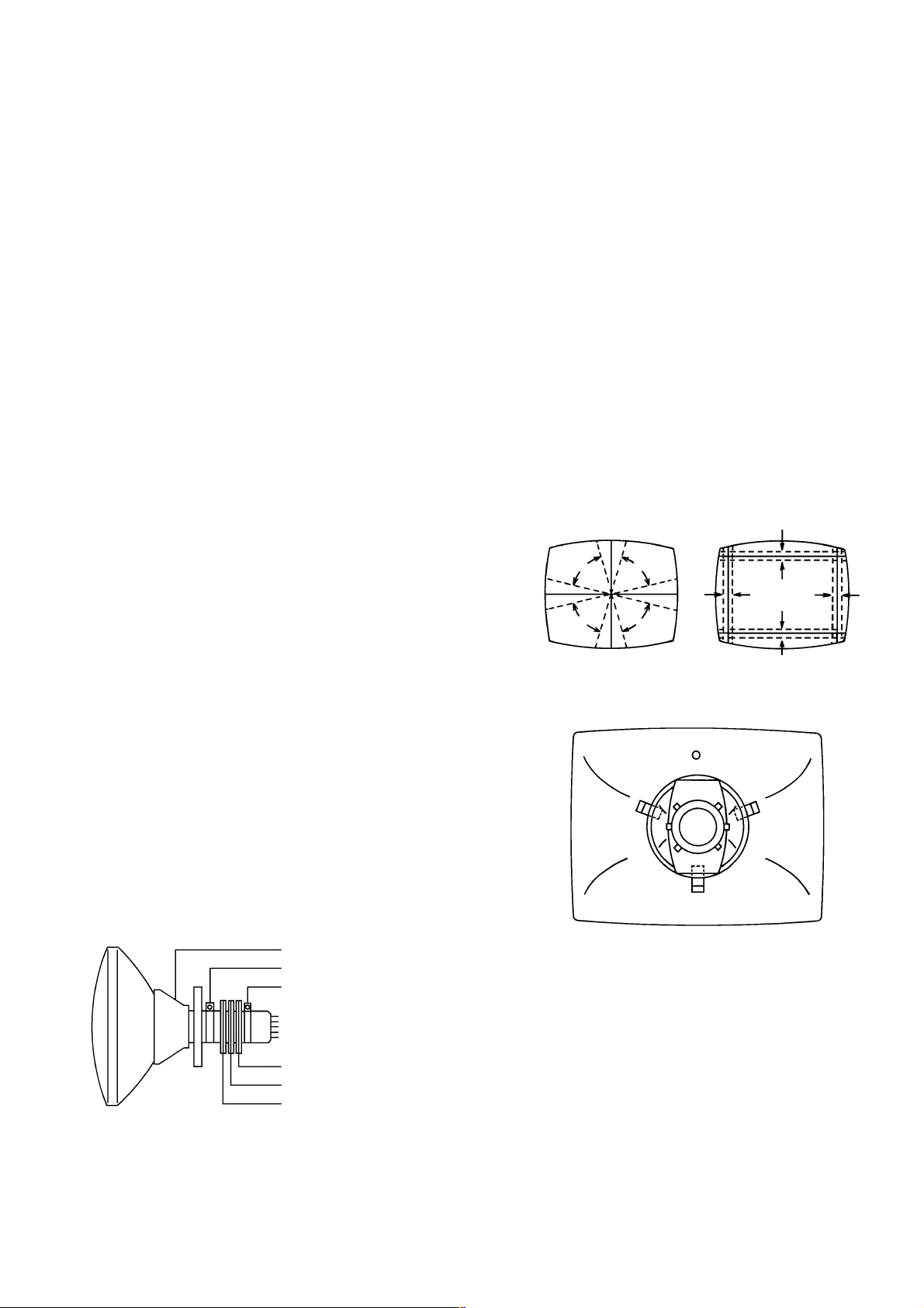
4-4: DYNAMIC CONVERGENCE
NOTE
Adjust after performing adjustments in section 4-3.
1.2.Adjust the differences around the screen by moving the
deflection yoke upward/downward and right/left.
(Refer to Fig. 4-2-a)
Insert three wedges between the deflection yoke and
CRT funnel to fix the deflection yoke.
(Refer to Fig. 4-2-b)
R G B
R
G
B
UPWARD/DOWNWARD SLANT RIGHT/LEFT SLANT
WEDGE
WEDGE POSITION
R
G
B
Fig. 4-2-a
WEDGE
WEDGE
Fig. 4-2-b
R G B
6 POLE MAGNETS
4 POLE MAGNETS
PURITY MAGNETS
Fig. 4-1
29
 Loading...