


 Loading...
SERVICE MANUAL
HD MEMORY CARD CAMERA RECORDER
GY-HM150U, GY-HM150E,
GY-HM150EC
* The illustration shows the GY-HM150U/GY-HM150E with the supplied microphone attached.
TABLE OF CONTENTS
1 |
PRECAUTION . . . . . . . . . . . . . . . . . . . . . . . . . . . . . . . . . . . . . . . . . . . . . . . . . . . . . . . . . . . . . . . . . . . . . . . . . . . . . . . . . . |
. 1-3 |
|
|
1.1 |
SAFETY PRECAUTIONS. . . . . . . . . . . . . . . . . . . . . . . . . . . . . . . . . . . . . . . . . . . . . . . . . . . . . . . . . . . . . . . . . . . . |
. 1-3 |
2 |
SPECIFIC SERVICE INSTRUCTIONS. . . . . . . . . . . . . . . . . . . . . . . . . . . . . . . . . . . . . . . . . . . . . . . . . . . . . . . . . . . . . . . . |
. 1-5 |
|
3 |
DISASSEMBLY . . . . . . . . . . . . . . . . . . . . . . . . . . . . . . . . . . . . . . . . . . . . . . . . . . . . . . . . . . . . . . . . . . . . . . . . . . . . . . . . . |
. 1-5 |
|
|
3.1 |
Removing the bottom cover assembly . . . . . . . . . . . . . . . . . . . . . . . . . . . . . . . . . . . . . . . . . . . . . . . . . . . . . . . . . . |
. 1-5 |
|
3.2 |
Removing the upper assembly . . . . . . . . . . . . . . . . . . . . . . . . . . . . . . . . . . . . . . . . . . . . . . . . . . . . . . . . . . . . . . . |
. 1-5 |
|
3.3 |
Removing the view finder assembly . . . . . . . . . . . . . . . . . . . . . . . . . . . . . . . . . . . . . . . . . . . . . . . . . . . . . . . . . . . |
. 1-6 |
|
3.4 |
Removing the boards and the OP block assembly . . . . . . . . . . . . . . . . . . . . . . . . . . . . . . . . . . . . . . . . . . . . . . . . |
. 1-7 |
|
3.5 |
Removing the upper assembly . . . . . . . . . . . . . . . . . . . . . . . . . . . . . . . . . . . . . . . . . . . . . . . . . . . . . . . . . . . . . . . |
. 1-8 |
|
3.6 |
Removing the monitor assembly . . . . . . . . . . . . . . . . . . . . . . . . . . . . . . . . . . . . . . . . . . . . . . . . . . . . . . . . . . . . . . |
. 1-9 |
|
3.7 |
Removing the view finder assembly . . . . . . . . . . . . . . . . . . . . . . . . . . . . . . . . . . . . . . . . . . . . . . . . . . . . . . . . . . . |
. 1-9 |
|
3.8 |
Removing the OP block assembly . . . . . . . . . . . . . . . . . . . . . . . . . . . . . . . . . . . . . . . . . . . . . . . . . . . . . . . . . . . . . |
1-11 |
|
3.9 |
Removing the audio unit . . . . . . . . . . . . . . . . . . . . . . . . . . . . . . . . . . . . . . . . . . . . . . . . . . . . . . . . . . . . . . . . . . . . |
1-11 |
4 |
ADJUSTMENT . . . . . . . . . . . . . . . . . . . . . . . . . . . . . . . . . . . . . . . . . . . . . . . . . . . . . . . . . . . . . . . . . . . . . . . . . . . . . . . . . . |
1-13 |
|
|
4.1 |
INSTRUMENTS REQUIRED FOR ADJUSTMENT AND THE SETUP . . . . . . . . . . . . . . . . . . . . . . . . . . . . . . . . . |
1-13 |
|
4.2 |
ADJUSTMENT . . . . . . . . . . . . . . . . . . . . . . . . . . . . . . . . . . . . . . . . . . . . . . . . . . . . . . . . . . . . . . . . . . . . . . . . . . . . |
1-14 |
5 |
TROUBLE SHOOTING. . . . . . . . . . . . . . . . . . . . . . . . . . . . . . . . . . . . . . . . . . . . . . . . . . . . . . . . . . . . . . . . . . . . . . . . . . . . |
1-20 |
|
|
5.1 |
SERVICE MENUS . . . . . . . . . . . . . . . . . . . . . . . . . . . . . . . . . . . . . . . . . . . . . . . . . . . . . . . . . . . . . . . . . . . . . . . . . |
1-20 |
|
5.2 |
HOW TO UPDATE THE FIRMWARE . . . . . . . . . . . . . . . . . . . . . . . . . . . . . . . . . . . . . . . . . . . . . . . . . . . . . . . . . . |
1-25 |
|
5.3 |
PRECAUTIONS WHEN CHANGING BOARDS . . . . . . . . . . . . . . . . . . . . . . . . . . . . . . . . . . . . . . . . . . . . . . . . . . . |
1-26 |
|
5.4 |
Checking emergency history with SSS. . . . . . . . . . . . . . . . . . . . . . . . . . . . . . . . . . . . . . . . . . . . . . . . . . . . . . . . . . |
1-27 |
|
5.5 |
EEPROM . . . . . . . . . . . . . . . . . . . . . . . . . . . . . . . . . . . . . . . . . . . . . . . . . . . . . . . . . . . . . . . . . . . . . . . . . . . . . . . . |
1-28 |
|
5.6 |
SSS (Service Support System) . . . . . . . . . . . . . . . . . . . . . . . . . . . . . . . . . . . . . . . . . . . . . . . . . . . . . . . . . . . . . . |
1-30 |
COPYRIGHT © 2012 JVC KENWOOD Corporation
No.HC044<Rev.001>
2012/4

SPECIFICATION
|
GY-HM150U |
GY-HM150E |
GY-HM150EC |
General
|
Power |
DC 11 V (using AC adapter) |
|
|
|
|
DC 7.2 V (using battery) |
|
|
Power consumption |
Approx. 8.3 W (when backlight is set to [STANDARD] while the LCD monitor or viewfinder is in use) |
|||
|
Dimensions |
366 mm (W) × 179 mm (H) × 138 mm (D)(14-4/8" x 7-1/8" x 5-4/8") |
|
|
|
Mass |
Approx. 1190 g (2.7 Ibs) |
|
|
|
|
Approx. 1320 g (2.9 Ibs) (incl. battery BN-VF823U, SD card, micorophone) |
|
|
Allowable operating temperature |
0 °C to 40 °C (32 °F to 104 °F) |
|
|
|
Allowable operating humidity |
35 % RH to 80 % RH |
|
|
|
Allowable storage temperature |
-20 °C to 50 °C (-4 °F to 122 °F) |
|
|
|
Image pickup device |
1/4", Progressive CCD × 3 |
|
|
|
|
Lens |
F1.8 to 2.8 |
|
|
|
|
f = 3.7 mm to 37 mm |
|
|
Filter diameter |
When the hood is |
46 mm (screw pitch: 0.75 mm) |
|
|
|
detached |
Compatible with filter (external diameter: 50 mm and below),tele-converter, and wide-converter |
||
|
When the hood is |
72 mm (screw pitch: 0.75 mm) |
|
|
|
attached |
Compatible with filter (external diameter: 75 mm and below) only |
|
|
|
|
* When removing the filter, do not press on the top and bottom of the hood. Doing so makes it difficult to remove the filter and may |
||
|
|
damage the inner surface of the hood. |
|
|
|
Zoom |
Up to 10x (optical zoom) |
|
|
|
LCD screen |
2.7", 16:9, 230,000 pixels |
|
|
|
Viewfinder |
0.24", 16:9, 260,000 pixels |
|
|
Video/Audio |
|
|
|
|
|
Recording time |
Approx. 25 minutes (8 GB SDHC/SDXC card, 35 Mbps, VBR mode) |
|
|
Video recording file |
QuickTime File |
Format(For Final Cut Pro) |
|
|
format |
MP4 File Format (HD only) |
|
|
|
|
AVI File Format (SD only) |
|
|
|
|
Video signal |
HD (HQ mode):MPEG-2 Long GOP |
|
|
|
|
VBR, 35 Mbps (Max) MPEG-2 |
|
|
|
|
HD (SP mode):MPEG-2 Long GOP |
|
|
|
|
CBR, 25 Mbps (1440x1080i) /19 Mbps(1280x720p) MPEG-2 |
|
|
|
SD |
DV |
DV |
|
|
|
CBR, 25 Mbps (720x480i) |
CBR, 25 Mbps (720x576i) |
|
|
Audio signal |
LPCM 2ch, 48 kHz/16 Bit |
|
|
Video format |
NTSC setting |
HD (HQ mode):1920x1080/59.94i, 29.97p, 23.98p, 1440x1080/59.94i, 1280x720/59.94p, 29.97p, 23.98p |
||
|
|
HD (SP mode):1440x1080/59.94i, 1280x720/59.94p, 29.97p, 23.98p |
|
|
|
|
SD:720x480/59.94i |
- |
|
|
PAL setting |
HD (HQ mode):1920x1080/50i, 25p, 1440x1080/50i, 1280x720/50p, 25p |
|
|
|
|
HD (SP mode):1440x1080/50i, 1280x720/50p, 25p |
|
|
|
|
- |
SD:720x576/50i |
|
Terminals |
|
|
|
|
|
AV terminal |
Video Analog output 1.0 V (p-p), 75 Ω Audio Analog output (stereo) |
|
|
|
|
-8 dBu, 1 k Ω (when reference level -12 dB is selected) |
|
|
|
|
-16 dBu, 1 k Ω (when reference level -20 dB is selected) |
|
|
Component terminal |
Y, PB, PR component output |
|
|
|
|
|
Y: 1.0 V (p-p), 75 Ω |
|
|
|
|
PB, PR: 700 mV (p-p), 75 Ω |
|
|
|
HDMI terminal |
HDMITM Connector |
|
|
|
USB terminal |
Mini USB-B type, USB 2.0 |
|
|
|
Headphone jack |
3.5 mm mini jack (stereo) |
|
|
|
Remote terminal |
3.5 mm mini jack (4-pin) |
|
|
Audio INPUT1/ |
MIC |
-60 dBu, 3 kΩ, XLR (balanced), +48 V output (phantom power supply) |
|
|
INPUT2 terminals |
|
|
|
|
LINE |
+4 dBu, 10 k Ω, XLR (balanced) |
|
|
|
Accessories |
|
|
|
|
|
|
AC adapter, Power cord×2, Battery, Battery |
AC adapter, Power cord×4, Battery, Battery |
AC adapter, Power cord, Remote control |
|
|
charger, Remote control unit, Audio unit,Mi- |
charger, Remote control unit, Audio unit,Mi- |
unit, Audio unit,Microphone,AV cord,Com- |
|
|
crophone,AV cord,Component cable,CD- |
crophone,AV cord,Component cable,CD- |
ponent cable,CD-ROM,Instruction manu- |
|
|
ROM,Instruction manual,Warranty card |
ROM,Instruction manual |
al,Warranty card |
AC Adapter |
|
|
|
|
|
Power |
AC 100 V to 240 V, 50 Hz/60 Hz |
|
|
|
Output |
DC 11 V =, 1 A |
|
|
Allowable operating temperature |
0 °C to 40 °C (32 °F to 104 °F) |
|
|
|
|
Dimensions |
49 mm (W) × 26 mm (H) × 64 mm (D)(1-15/16" × 1-1/ 8" × 2-7/8") |
47 mm (W) × 28 mm (H) × 72 mm (D) |
|
|
|
(excluding cord and AC plug) |
|
(excluding cord and AC plug) |
|
Mass |
Approx. 86 g (0.19 Ibs) |
|
|
Remote Control Unit |
|
|
|
|
|
Type |
DC 3 V (button battery CR2025) |
|
|
|
Battery life |
Approx. 1 year (varies according to frequency of use) |
|
|
Operating distance |
Approx. 5 m (16.4 ft) (along front axis) |
|
|
|
Allowable operating temperature |
0 °C to 40 °C (32 °F to 104 °F) |
|
|
|
|
Dimensions |
42 mm (W) × 14.5 mm (H) × 91 mm (D)(1-6/8" × 9/16" × 3-5/ 8") |
|
|
|
Mass |
Approx. 30 g (0.07 Ibs)(including button battery) |
|
|
1-2 (No.HC044<Rev.001>)
SECTION 1 PRECAUTION
1.1SAFETY PRECAUTIONS
Prior to shipment from the factory, JVC products are strictly inspected to conform with the recognized product safety and electrical codes of the countries in which they are to be sold.However,in order to maintain such compliance, it is equally important to implement the following precautions when a set is being serviced.
1.1.1 Precautions during Servicing
(1)Locations requiring special caution are denoted by labels and inscriptions on the cabinet, chassis and certain parts of the product.When performing service, be sure to read and comply with these and other cautionary notices appearing in the operation and service manuals.
(2)Parts identified by the  symbol and shaded (
  ) parts are critical for safety.
Replace only with specified part numbers.
NOTE :
Parts in this category also include those specified to comply with X-ray emission standards for products using cathode ray tubes and those specified for compliance with various regulations regarding spurious radiation emission.
(3)Fuse replacement caution notice.
Caution for continued protection against fire hazard. Replace only with same type and rated fuse(s) as specified.
(4)Use specified internal wiring. Note especially:
•Wires covered with PVC tubing
•Double insulated wires
•High voltage leads
(5)Use specified insulating materials for hazardous live parts. Note especially:
•Insulation Tape
•PVC tubing
•Spacers
•Insulation sheets for transistors
•Barrier
(6)When replacing AC primary side components (transformers, power cords, noise blocking capacitors, etc.) wrap ends of wires securely about the terminals before soldering.
Fig.1-1-1
(7)Observe that wires do not contact heat producing parts (heatsinks, oxide metal film resistors, fusible resistors, etc.)
(8)Check that replaced wires do not contact sharp edged or pointed parts.
(9)When a power cord has been replaced, check that 10-15 kg of force in any direction will not loosen it.
Power cord
Fig.1-1-2
(10)Also check areas surrounding repaired locations.
(11)Products using cathode ray tubes (CRTs) In regard to such products, the cathode ray tubes themselves, the high voltage circuits, and related circuits are specified for compliance with recognized codes pertaining to X-ray emission. Consequently, when servicing these products, replace the
cathode ray tubes and other parts with only the specified parts. Under no circumstances attempt to modify these circuits.Unauthorized modification can increase the high voltage value and cause X-ray emission from the cathode ray tube.
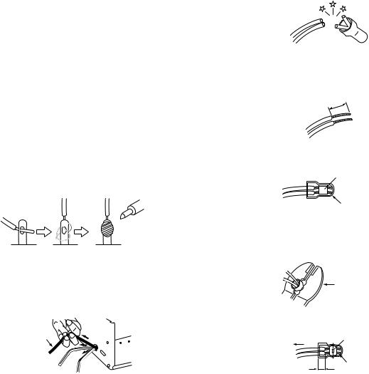
(12)Crimp type wire connector In such cases as when replacing the power transformer in sets where the connections between the power cord and power trans former primary lead wires are performed using crimp type connectors, if replacing the connectors is unavoidable, in order to prevent safety hazards, perform carefully and precisely according to the following steps.
•Connector part number :E03830-001
•Required tool : Connector crimping tool of the proper type which will not damage insulated parts.
•Replacement procedure
a)Remove the old connector by cutting the wires at a point close to the connector.Important : Do not reuse a connector (discard it).
cut close to connector
Fig.1-1-3
b)Strip about 15 mm of the insulation from the ends of the wires. If the wires are stranded, twist the strands to avoid frayed conductors.
15 mm
Fig.1-1-4
c)Align the lengths of the wires to be connected. Insert the wires fully into the connector.
Metal sleeve
Connector
Fig.1-1-5
d)As shown in Fig.1-1-6, use the crimping tool to crimp the metal sleeve at the center position. Be sure to crimp fully to the complete closure of the tool.
25 |
Crimping tool |
1. |
|
2. |
|
0 |
|
5. |
|
5 |
|
Fig.1-1-6
e) Check the four points noted in Fig.1-1-7.
Not easily pulled free |
Crimped at approx. center |
|
of metal sleeve |
||
|
||
|
Conductors extended |
Wire insulation recessed more than 4 mm
Fig.1-1-7
(13)Battery replacement caution notice.
CAUTION RISK OF EXPLOSION IF BATTERY IS REPLACED BY AN INCORRECT TYPE.
DISPOSE OF USED BATTERIES ACCORDING TO THE INSTRUCTIONS.
(No.HC044<Rev.001>)1-3

1.1.2 Safety Check after Servicing
Examine the area surrounding the repaired location for damage or deterioration. Observe that screws, parts and wires have been returned to original positions, Afterwards, perform the following tests and confirm the specified values in order to verify compliance with safety standards.
(1)Insulation resistance test
Confirm the specified insulation resistance or greater between power cord plug prongs and externally exposed parts of the set (RF terminals, antenna terminals, video and audio input and output terminals, microphone jacks, earphone jacks, etc.).See table 1 below.
(2)Dielectric strength test
Confirm specified dielectric strength or greater between power cord plug prongs and exposed accessible parts of the set (RF terminals, antenna terminals, video and audio input and output terminals, microphone jacks, earphone jacks, etc.). See Fig.1-1-11 below.
(3)Clearance distance
When replacing primary circuit components, confirm specified clearance distance (d), (d') between soldered terminals, and between terminals and surrounding metallic parts. See Fig.1-1-11 below.
d
d'
Chassis
Power cord primary wire
Fig.1-1-8
(4)Leakage current test
Confirm specified or lower leakage current between earth ground/power cord plug prongs and externally exposed accessible parts (RF terminals, antenna terminals, video and audio input and output terminals, microphone jacks, earphone jacks, etc.).
Measuring Method : (Power ON) Insert load Z between earth ground/power cord plug prongs and externally exposed accessible parts. Use an AC voltmeter to measure across both terminals of load Z. See Fig.1-1-9 and following Fig.1-1-12.
|
|
a |
b |
Externally |
Z |
A |
c |
|
|||
|
|
|
|
exposed |
V |
|
|
accessible part |
|
|
|
Fig.1-1-9
(5)Grounding (Class 1 model only)
Confirm specified or lower grounding impedance between earth pin in AC inlet and externally exposed accessible parts (Video in, Video out, Audio in, Audio out or Fixing screw etc.).Measuring Method:
Connect milli ohm meter between earth pin in AC inlet and exposed accessible parts. See Fig.1-1-10 and grounding specifications.
AC inlet |
Exposed accessible part |
Earth pin |
MIlli ohm meter |
|
|
|
Grounding Specifications |
|
|
|
Region |
Grounding Impedance (Z) |
||
|
|
|
|
USA & Canada |
Z |
|
0.1 ohm |
|
|
|
|
Europe & Australia |
Z |
|
0.5 ohm |
Fig.1-1-10
AC Line Voltage |
Region |
|
|
|
|
|
( ) |
Dielectric Strength |
|
Clearance Distance (d), (d') |
|||||||||||
Insulation Resistance R |
|
||||||||||||||||||||
100 V |
Japan |
R |
|
|
1 M /500 V DC |
AC 1 kV 1 minute |
|
|
d, d' |
3 mm |
|||||||||||
|
|
|
|
|
|
|
|
|
|
|
|
|
|||||||||
100 to 240 V |
|
|
AC 1.5 kV 1 minute |
|
|
d, d' |
4 mm |
||||||||||||||
|
|
|
|
|
|
|
|
|
|
|
|
|
|||||||||
|
|
|
|
|
|
|
|
|
|
|
|
|
|
|
|
|
|
|
|||
110 to 130 V |
USA & Canada |
1 M |
|
|
|
R |
|
12 M /500 V DC |
AC 1 kV 1 minute |
|
|
d, d' |
|
|
3.2 mm |
||||||
|
|
|
|
|
|
|
|
|
|
|
|
|
|
|
|
|
|
|
|||
110 to 130 V |
|
|
|
|
|
|
|
|
|
|
|
AC 3 kV 1 minute |
|
d |
|
4 mm |
|
||||
Europe & Australia |
R |
10 M /500 V DC |
|
|
(Class |
) |
d' |
|
8 mm |
(Power cord) |
|||||||||||
|
|
|
|
||||||||||||||||||
200 to 240 V |
AC 1.5 kV 1 minute |
|
|
||||||||||||||||||
|
|
|
|
|
|
|
|
|
|
|
|
d' |
|
6 mm (Primary wire) |
|||||||
|
|
|
|
|
|
|
|
|
|
|
|
|
|
(Class |
) |
|
|||||
|
|
|
|
|
|
|
|
|
|
|
|
|
|
||||||||
|
|
|
|
|
|
|
|
|
Fig.1-1-11 |
|
|
|
|
|
|
|
|
|
|
||
|
|
|
|
|
|
|
|
|
|
|
|
|
|
|
|
|
|
||||
AC Line Voltage |
Region |
|
|
|
|
|
|
Load Z |
Leakage Current (i) |
|
|
|
|
a, b, c |
|||||||
100 V |
Japan |
|
|
|
|
|
1 |
|
|
i |
|
1 mA rms |
|
Exposed accessible parts |
|||||||
|
|
|
|
|
|
|
|
|
|
|
|
|
|
|
|
|
|
|
|||
|
|
|
|
|
|
|
|
|
|
|
|
|
|
|
|
|
|
|
|||
110 to 130 V |
USA & Canada |
0.15 |
|
|
|
|
|
|
i |
|
0.5 mA rms |
|
Exposed accessible parts |
||||||||
|
|
|
|
|
1.5 |
|
|
||||||||||||||
|
|
|
|
|
|
|
|||||||||||||||
|
|
|
|
|
|
|
|
|
|
|
|
|
|
|
|
|
|||||
110 to 130 V |
|
|
|
|
|
|
2 |
|
|
i |
|
0.7 mA peak |
|
Antenna earth terminals |
|||||||
Europe & Australia |
|
|
|
|
|
|
|
i |
|
2 mA dc |
|
||||||||||
|
|
|
|
|
|
|
|
|
|
|
|
|
|
|
|||||||
220 to 240 V |
|
|
|
|
|
|
|
|
|
|
|
|
|
|
|
|
|
|
|
|
|
|
|
|
|
|
|
|
|
|
|
i |
|
0.7 mA peak |
|
Other terminals |
|||||||
|
|
|
|
|
|
|
|
|
|
|
|
|
|||||||||
|
|
|
|
|
|
|
50 |
|
i |
|
2 mA dc |
|
|||||||||
|
|
|
|
|
|
|
|
|
|
|
|
|
|
|
|
||||||
|
|
|
|
|
|
|
|
|
|
|
|
|
|
|
|
|
|
|
|
|
|
Fig.1-1-12
NOTE :
These tables are unofficial and for reference only. Be sure to confirm the precise values for your particular country and locality.
1-4 (No.HC044<Rev.001>)
SECTION 2
SPECIFIC SERVICE INSTRUCTIONS
This service manual does not describe SPECIFIC SERVICE INSTRUCTIONS.
SECTION 3
DISASSEMBLY
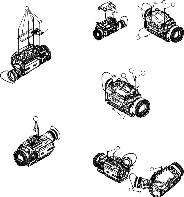
3.1Removing the bottom cover assembly (See Figure 1)
(1)Remove the seven screws A attaching the bottom cover assembly.
• The screws indicated with the marks need not be removed.
A
Bottom cover assembly
Fig.1
3.2Removing the upper assembly (See Figure 2, Figure 3, Figure 4, Figure 5, Figure 6, Figure 7, Figure 8)
(1)Remove the four screws A attaching the shoe assembly, then remove the shoe assembly.
A
Shoe assembly
(2)Remove the four screws B attaching the grip cover, then remove the grip cover.
•Before attaching the grip cover, attach the three tabs on the grip cover first.
Grip cover |
B |
B |
Tabs
B
Fig.3
(3)Remove the two screws C and the two screws D attaching the jack cover, then remove the jack cover.
Screw C: Short Screw D: Long
Open the
mic cover D
D
C
a
The Jack cover is done in
the slide while pushing arrow "a" part.
 Jack cover assembly
C
Fig.4
(4) Remove the three screws E and the one screw F attaching the upper cover assembly, then remove the upper cover assembly.
Screw E: Short Screw F: Long
E
Upper cover assembly
Fig.2 |
E |
F
Fig.5
(No.HC044<Rev.001>)1-5

(5) Remove the four screws G and the one screw H attaching the case (HDD), then remove the case (HDD).
Screw G: Short Screw H: Long
G
H
Case (HDD)
G
Fig.6
(6)Remove the one screw J and the one screw K attaching the OPE unit.
Screw J: Short |
Screw K: Long |
(7)Pull out the wire from the connector CN204 on the ANALOG board, then remove the OPE unit.
J


 OPE Unit


 CN204 K
ANALOG
Board
Fig.7
(8) Remove the six screws L and the one screw M attaching the upper assembly.
Screw L: Short Screw M: Long
(9)Pull out the wire from the connector CN107 on the MAIN board, then remove the upper assembly.
•When attaching the upper assembly, be sure to set the two tabs firmly.
Set the tabs firmly
Upper assembly
 L
L
 Set the tabs firmly
CN107
MAIN Board
L 


 M
M
L
L 
Fig.8
1-6 (No.HC044<Rev.001>)
3.3Removing the view finder assembly (See Figure 9, Figure 10, Figure 11)
(1)Remove the four screws A attaching the rear cover assembly, then remove the rear cover assembly.
A
Rear cover 

 A assembly
Fig.9
(2)Remove the one screw B attaching the REAR board.
(3)Pull out the wire from the connector CN6001 on the MAIN board, then remove the REAR board.
REAR Board
B
CN6001
MAIN Board
Fig.10
(4)Pull out the wire from the connector CN205 on the ANALOG board.
(5)Remove the five screws C attaching the view finder assembly, then remove the view finder assembly.
C
CN205
ANALOG Board


 View finder assembly
 C
C
Fig.11

3.4Removing the boards and the OP block assembly (See Figure 12, Figure 13, Figure14, Figure 15, Figure 16, Figure 17, Figure 18, Figure 19, Figure 20)
(1)Pull out the wire from the connector CN108 on the MAIN board.
(2)Remove the three screws A attaching the focus ring assembly, then remove the focus ring assembly.
A |
CN108 |
A |
|
||
MAIN Board |
|
|
|
|
A
Focus ring assembly
Fig.12
(3)Remove the two screws B attaching the MIC assembly.
(4)Pull out the wire from the connector CN206 on the ANALOG board, then remove the MIC assembly.
 B
B

 MIC Assembly

 CN206
CN206
Fig.13
(5)Remove the four screws C attaching the bracket (bottom) and the bracket (frame), then remove each bracket.
C |
Bracket (Bottom) |
|
C
C
Bracket (Frame)
Fig.14
(6)Pull out the wires from the connectors CN201, CN202, and CN203 on the ANALOG board.
(7)Remove the two screws D attaching the ANALOG board, then remove the ANALOG board.
D |
CN201 |
|
ANALOG |
||
D |
||
Board |
|
|
CN203 |
|
|
|
CN202 |
 CN6003
Fig.15
(8)Remove the three screws E attaching the bracket (MAIN).
(9)Pull out the wire from the connector CN901 on the SD board, then remove the bracket (MAIN) and the SD board.
(10)Pull out the wires from the connectors CN103, CN6003, and CN110 on the MAIN board, then remove the MAIN board.
 E
E
E
 CN901
CN901
SD Board

 CN103
CN103
CN110 
MAIN
Board
Fig.16
(11)Remove the three screws F attaching the heat sink (MAIN), then remove the heat sink (MAIN).
F 

 F
F
Heat sink (MAIN)
Fig.17
(No.HC044<Rev.001>)1-7

(12)Disconnect the B to B connector from the connector CN5001 on the CDS board.
(13)Remove the three screws G attaching the OP block assembly, then remove the OP block assembly.
G 
 G
G
OP Block assembly
CN5001
CDS Board
Fig.18
(14)Remove the two screws H attaching the JACK board, then remove the JACK board.
 H
H
JACK
Board
Fig.19
(15)Remove the two screws J attaching the CDS board and the bracket (CDS), then remove the CDS board and the bracket (CDS).


 J
J
CDS Board and bracket (CDS)
Fig.20
3.5Removing the upper assembly (See Figure 21, Figure 22, Figure 23, Figure 24, Figure 25)
•Remove the upper assembly from the main unit.
(1)Remove the two screws A attaching the CU sheet, then remove the CU sheet.
(2)Pull out the wire from the connector CN623 on the OPE4 board.
(3)Remove the one screw B attaching the speaker, then remove the speaker and the bracket (SPK).
Process wire to this notch. |
B |
Bracket (SPK) |
|
|
|
|
|
|
|
Speaker |
|
A |
CU Sheet |
|
CN623 |
|
|
|
|
Fig.21
(4)Pull out the wires from the connectors CN621, CN624, CN622 and CN626 on the OPE4 board.
(5)Remove the one screw C and the two screws D attaching the OPE4 board, then remove the OPE4 board.
Screw C: Silver |
Screw D: Black |
|
|
D |
C |
CN621
D
|
CN622 |
CN626 |
OPE4 Board |
|
CN624
Fig.22
(6)Remove the two screws E attaching the cover (upper), then remove the cover (upper).
(7)Remove the two screws F attaching the monitor assembly, then remove the monitor assembly.
E
F
Cover (upper)
Fig.23
(8)Remove the four screws G attaching the OPE2 board and the OPE3 board, then remove each board.
•When attaching the OPE2 board and OPE3 board, make sure that each pair of switches and knobs aligns at four positions.
G
G
OPE3 Board
OPE2 Board
 Fix the screws after confirming the position of switch and knob.
Fig.24
1-8 (No.HC044<Rev.001>)

(9)Remove the two screws H and the one screw J attaching the frame (upper).
(10)Remove the four tabs, then remove the frame (upper).
(11)Remove the one screw K attaching the OPE1 board assembly, then remove the OPE1 board assembly.
Tab |
Frame (upper) |
|
|
H |
|
Tabs |
J |
K |
|
OPE1 


 Board
Board 

 assembly
Fig.25
3.6Removing the monitor assembly (See Figure 26, Figure 27)
• Removing the monitor assembly from the upper assembly.
(1)Remove the two screws A and the two screws B attaching the monitor cover assembly, then remove the monitor cover assembly.
Screw A: Narrow |
Screw B: Thick |
(2)Pull out the wires from the connectors CN701, and CN703 on the MONI board, then remove the hinge unit assembly.
Monitor cover assembly
Hinge unit |
A |
|
assembly |
||
|
CN701
CN703 |
B |
Fig.26
(3)Removing the four screws C attaching the bracket (LCD) enables to release each part.
•When assembling the parts, be careful with the assembling order and direction of each part.
•Do not push the LCD surface as it may be damaged.
•Be careful in handling the surface of the LCD and the monitor, and do not damage, soil, or leave fingerprints. If the surfaces are soiled, gently wipe them off with soft cloth.
C
MONI Board
LCD Bracket
Sheet (M.REF)
Spacer (LCD)
|
Light guide |
LCD Module |
|
Support plate |
|
side |
Sheet (M.DIFF) |
|
LCD Case
Sheet BEF
Turn
Put it on slit of MONI case.
MONI Case assembly
Fig.27
3.7Removing the view finder assembly (See Figure 28, Figure 29, Figure 30, Figure 31, Figure 32, Figure 33)
•Remove the view finder assembly from the main unit.
(1)Remove the eye cap.
•When attaching the eye cap, align the positions as shown in the figure.
Match and attach this position.
 Eye cap
Fig.28
(No.HC044<Rev.001>)1-9

(2)Remove the two screws A attaching the upper cover (VF), then remove the upper cover (VF).
Upper cover (VF) 

A
Fig.29
(3)Remove the one screw B attaching the wire.
(4)Remove the two screws C and the two screws D attaching the holder (VF) assembly, then remove the holder (VF) as-
sembly. |
|
Screw C: Short |
Screw D: Long |
B |
|
|
D |
|
C |
|
Holder (VF) |
|
assembly |
Fig.30
(5)Remove the four screws E attaching the bottom case (VF), then remove the bottom case (VF).
(6)Remove the two screws F attaching the LCD module assembly, then remove the LCD module assembly.
F E 
F

 LCD Module assembly
Bottom case (VF)
Fig.31
(7)Remove the two tabs, then remove the front cover (VF).
•Removing the front cover (VF) enables to release the lens and other parts.
Front cover (VF)
Lens holder assembly
Tabs
Fig.32
(8)The parts on the LCD module assembly are fixed only with the tabs. When assembling the parts, be careful with the attaching order and direction of each part.
LCOS Bracket
Note the boss breaking.
LCOS Cover
Support plate side
LCD Module
LCOS Holder
Terminal side
Terminal side
VF Board
FPC
Fig.33
1-10 (No.HC044<Rev.001>)
3.8Removing the OP block assembly (See Figure 34, Figure 35, Figure 36, Figure 37)
•Remove the OP block from the main unit.
(1)Pull out the wire connected to the ROIS unit.
(2)Remove the two screws A attaching the ROIS unit, then remove the ROIS unit.
•Do not blow the lens inside the ROIS (on the OP block) with air. Never touch the lens.

 ROIS Unit
Connector
A
Fig.34
(3)Unsolder the soldered points on the CCD board, then remove the CCD board.
(4)Remove the one screw B attaching the heat sink (CCD) assembly, then remove the heat sink (CCD) assembly.
B
Heat sink (CCD) assembly
Fig.35
(5)Remove the three screws C attaching the prism assembly, then remove the prism assembly.
Prism assembly
C
Fig.36
(6)Unsolder the soldered points on the zoom motor unit and the focus motor unit.
•Be careful not to break or damage the wire by soldering (overheated).
(7)Remove the six screws D and the one screw E attaching the iris motor unit, zoom motor unit, and the focus motor unit, then remove each part.
•As the spring comes off when the zoom motor unit and the focus motor unit are removed, be careful not to loose the spring.
•See the figure when attaching the spring.
 E
E
D 


 D
D
Iris motor unit
D
Zoom motor unit 
Spring
|
Focus motor |
|
unit |
Slide part (Motor side) |
|
|
Spring |
|
Hook |
Slide part |
Spring |
Hook |
|
(OP Block side)
Fig.37
3.9Removing the audio unit (See Figure 38, Figure 39, Figure 40, Figure 41, Figure 42, Figure 43, Figure 44, Figure 45)
(1)Remove the four screws A attaching the cover (TOP), then remove the cover (TOP).
(2)Remove the two screws B attaching the shoe assembly, then remove the shoe assembly.
|
A |
A |
|
B |
Shoe assembly |
|
|
Cover (TOP) |
|
Fig.38
(3)Remove the one screw C attaching the AU cover (FR) assembly, then remove the AU cover (FR) assembly.
C
 AU Cover (FR) assembly
Fig.39
(No.HC044<Rev.001>)1-11
Loading...