


 Loading...
HA-RF100S (J)
SERVICE MANUAL
WIRELESS ENTERTAINMENT SYSTEM
HA-RF100S (J)
Specifications
|
Contents |
|
Specifications ............................... |
Front cover |
|
Safety precautions ..................................... |
2 |
|
1. |
Operation manual ................................ |
2 |
2. |
Disassembly ........................................ |
15 |
3. |
Schematic diagrams ............................ |
17 |
4. |
Measurement condition ....................... |
19 |
5. |
Wiring diagrams .................................. |
19 |
6. |
Block diagrams ................................... |
21 |
7. |
Electrical parts list................................ |
22 |
8. |
Explode view ....................................... |
23 |
9. |
Mechanical parts list ........................... |
25 |
10. Packing method ................................ |
26 |
|
11. Packing materials parts list ............... |
28 |
|
12. Accessoriers list ................................ |
29 |
|
General Specifications
Modulation system |
: Stereo frequency modulation system |
Carrier frequency |
: 911 MHz --- 914 MHz |
Usable area |
|
(distance to reach) |
: Approx. 150 ft (46 m) (using JVC |
|
measurements systems) |
Distortion |
: Less than 4 % (at 1 kHz) |
Transmitter (J21738-002) |
|
Power requirements |
: DC 12 V (with the exclusive AC adaptor |
|
J46598-001) |
Audio input terminal |
: RCA pin jack x 2 |
|
3.5 mm dia. stereo minijack |
Input impedance |
: 20 kOhms |
Reference input level |
: 350 mV |
Dimensions |
: 140(W) x 128(D) x 230(H) mm |
|
(5-9/16" x 5-1/16" x 9-1/16") |
Weight |
: 315 g (11.1 oz) (Without connection |
|
cord and AC adaptor) |
Headphones (HA-W100RF) |
|
Power requirements |
: Rechargeable Ni-Cd battery (1.2 V) x 2 |
Battery running time |
: 13 hours (When charged for 19 hours) |
Frequency response |
: 50 Hz --- 12,000 Hz |
Weight |
: 300 g (10.6 oz) (With provided |
|
rechargeable Ni-Cd battery x 2) |
Speakers (SP-A100RF)
Power requirements |
: DC 9 V (with the exclusive AC adaptor |
|
J46906-001) or D size battery (1.5 V) |
|
x 6 (each channel) |
Battery running time |
: 24 hours (when use Alkaline batteries) |
Frequency response |
: 65 Hz --- 16,000 Hz |
Dimensions |
: 150(W) x 175(D) x 280(H) mm |
|
(5-15/16" x 6-15/16" x 11-1/16") |
Weight |
: 3.0 kg (6.7 lbs) (without batteries and |
|
AC adaptor) (each channel) |
Provided Accessories |
|
Instructions x 1 |
|
AC adaptor x 3 |
|
Connection cord x 1 |
(3.5 mm dia. stereo miniplug --- RCA pin |
|
plug x 2 : 1.8 m (5.9 ft)) |
Charging cable x 1 |
(2.5 mm dia. mono plug --- 2.5 mm dia. |
|
mono plug) |
Plug adaptor x 1 |
(converts 3.5 mm dia. stereo miniplug to a |
|
6.3 mm dia. standard stereo phone plug) |
Exclusive |
|
rechargeable |
|
Ni-Cd battery |
x 2 (for headphones) |
* Design and specifications subject to change without notice.
COPYRIGHT 2000 VICTOR COMPANY OF JAPAN, LTD.
No.70248
Oct. 2000
HA-RF100S(J)
Safety precautions
1. This design of this product contains special hardware and many circuits and components specially for safety purposes. For continued protection, no changes should be made to the original design unless authorized in writing by the manufacturer. Replacement parts must be identical to those
used in the original circuits. |
Services |
should be performed by qualified personnel only. |
||
2. Alterations of the design or |
circuitry |
of |
the product should not be made. |
Any design alterations of |
the product should not be made. |
Any |
design alterations or additions will |
void the manufacturer`s |
|
warranty and will further relieve the manufacture of responsibility for personal injury or property
damage resulting therefrom. |
|
|
3. Many |
electrical and mechanical parts in the products |
have special safety-related characteristics. |
These |
characteristics are often not evident from visual |
inspection nor can the protection afforded |
by them necessarily be obtained by using replacement components rated for higher voltage, wattage, etc. Replacement parts which have these special safety characteristics are identified in the Parts List of Service Manual. Electrical components having such features are identified by shading on the schematics and by ( ) on the Parts List in the Service Manual. The use of a substitute replacement which does not have the same safety characteristics as the recommended replacement parts shown in the Parts List of Service Manual may create shock, fire, or other hazards.
4. The |
leads |
in the products are routed and dressed with ties, clamps, tubings, barriers and the |
like |
to be |
separated from live parts, high temperature parts, moving parts and/or sharp edges |
for the prevention |
of electric |
shock and fire hazard. When service is required, the original lead |
||||
routing and dress |
should be |
observed, |
and it should be confirmed |
that |
they |
have been returned |
to normal, after re-assembling. |
|
|
|
|
||
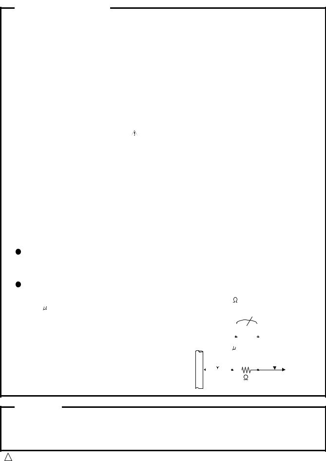
5. Leakage currnet check (Electrical shock hazard testing) |
|
|
|
|||
After re-assembling the product, always |
perform an isolation check |
on |
the |
exposed metal parts |
||
of the product (antenna terminals, knobs, metal cabinet, screw heads, headphone jack, control
shafts, etc.) to be sure the product is safe to operate without danger |
|
of |
electrical shock. |
||||||||||||||||||||
Do not use a line isolation transformer during this check. |
|
|
|
|
|
|
|
|
|
|
|
|
|
|
|||||||||
Plug |
the |
AC |
line |
cord directly into the AC outlet. |
Using |
a "Leakage |
Current |
Tester", measure |
|||||||||||||||
the |
leakage |
current from each exposed |
metal parts of |
the |
cabinet , particularly any exposed |
||||||||||||||||||
metal part having a return path to the chassis, to a known |
good |
earth ground. Any leakage |
|||||||||||||||||||||
current must not exceed 0.5mA AC (r.m.s.) |
|
|
|
|
|
|
|
|
|
|
|
|
|
|
|
||||||||
Alternate |
check method |
|
|
|
|
|
|
|
|
|
|
|
|
|
|
|
|
|
|||||
Plug |
the |
AC line |
cord directly into the AC outlet. |
Use |
an |
AC voltmeter having, 1,000 ohms |
|||||||||||||||||
per volt or more |
sensitivity in |
the following manner. Connect a |
1,500 |
|
10W resistor paralleled by |
||||||||||||||||||
a 0.15 |
F AC-type |
capacitor |
between an |
exposed |
|
|
|
|
|
|
|
|
|
|
|
|
|
AC VOLTMETER |
|||||
metal part and a known good earth ground. |
|
|
|
|
|
|
|
|
|
|
|
|
|
|
|||||||||
|
|
|
|
|
|
|
|
|
|
|
|
|
|
(Having 1000 |
|||||||||
Measure the |
AC |
voltage across the resistor |
with the |
|
|
|
|
|
|
|
|
|
|
|
|
|
|||||||
|
|
|
|
|
|
|
|
|
|
|
|
|
ohms/volts, |
||||||||||
|
|
|
|
|
|
|
|
|
|
|
|
|
|||||||||||
AC voltmeter. |
|
|
|
|
|
|
|
|
|
|
|
|
|
|
|
|
|
|
or more sensitivity) |
||||
Move the |
resistor |
connection |
to eachexposed metal |
|
|
|
|
|
|
|
|
|
|
|
|
|
|
|
|||||
|
|
|
|
|
|
|
|
|
|
|
|
|
|
|
|||||||||
part, |
particularly |
any exposed metal part having a |
|
|
|
|
|
|
|
|
|
|
|
|
|
|
|||||||
|
|
|
|
0.15 |
|
|
F |
AC TYPE |
|
||||||||||||||
return |
path |
to the |
chassis, and meausre the AC |
|
|
|
|
|
|
|
|
|
|
|
|
|
|
Place this |
|||||
|
|
|
|
|
|
|
|
|
|
|
|
|
|
||||||||||
voltage |
across the |
resistor. Now, reverse the plug in |
|
|
|
|
|
|
|
|
|
|
|
|
|
|
|||||||
|
|
|
|
|
|
|
|
|
|
|
|
|
|
||||||||||
|
|
|
|
|
|
|
|
|
|
|
|
|
|
probe on |
|||||||||
the AC outlet and repeat each measurement. voltage |
|
|
|
|
|
|
|
|
|
|
|
|
|
|
|||||||||
|
|
|
|
|
|
|
|
|
|
|
|
|
|
each exposed |
|||||||||
|
|
|
1500 |
|
10W |
|
|||||||||||||||||
measured Any must |
not exceed 0.75 V AC |
(r.m.s.). |
|
|
|
|
|
metal part. |
|||||||||||||||
This |
corresponds to 0.5 mA AC (r.m.s.). |
|
Good earth ground |
|
|
|
|
|
|
|
|
|
|||||||||||
|
|
|
|
|
|
|
|
|
|
|
|
|
|
|
|
|
|
||||||
Warning
1. This equipment has been designed and manufactured to meet international safety standards.
2. It |
is |
the |
legal responsibility of the repairer to ensure that these safety standards are maintained. |
|
3. Repairs |
must be made in accordance with the relevant safety standards. |
|||
4. It |
is |
essential that safety |
critical components are replaced by approved parts. |
|
5. If |
mains |
voltage selector |
is provided, check setting for local voltage. |
|
! CAUTION Burrs formed during molding may be left over on some parts of the chassis. Therefore, pay attention to such burrs in the case of preforming repair of this system.
2

EN
|
RF100S-HA |
|
|
(J) |
|
|
|
|
VICTOR COMPANY OF JAPAN, LIMITED |
ENTERTAINMENT WIRELESS |
|
SYSTEM |
||
|
© 2000 VICTOR COMPANY OF JAPAN, LTD. |
Printed in China |
J5500-103B |
3
WIRELESS ENTERTAINMENT SYSTEM
HA-RF100S (J)
For Customer Use:
INSTRUCTIONS Enter below the Model No. and Serial No. which is located on the rear of the cabinet. Retain this information for future reference.
Model No.
Serial No.
J5500-103B
manual Operation .1
RF100S(J)-HA
4
Hearing Comfort and Well-Being
●Do not play your headphones at a high volume. Hearing experts advise against continuous extended play.
●If you experience a ringing in your ears, reduce volume or discontinue use.
Traffic Safety
●Do not use while operating a motorized vehicle. It may create a traffic hazard and is illegal in many areas.
●You should use extreme caution or temporarily discontinue use in potentially hazardous situations.
●Even though your headphones are of the open-air type designed to let you hear outside sounds, don't turn up the volume so high that you can't hear what's around you.
FCC INFORMATION
This device complies with Part 15 of the FCC Rules. Operation is subject to the following two conditions:
(1)This device may not cause harmful interference.
(2)This device must accept any interference received, including interference that may cause undesired operation.
CAUTION Changes or modifications not approved by JVC could void user's authority to operate the equipment.
Contact
Address: JVC AMERICAS CORP.
JVC COMPANY OF AMERICA
1700 Valley Road, Wayne, NJ 07470
Telephone: (973) 315-5000
Note: This equipment has been tested and found to comply with the limits for a Class B digital device, pursuant to Part 15 of the FCC rules. These limits are designed to provide reasonable protection against harmful interference in a residential installation. This equipment generates, uses and can radiate radio frequency energy and, if not installed and used in accordance with the instructions, it may cause harmful interference to radio communications. However, there is no guarantee that interference will not occur in a particular installation. If this equipment does cause harmful interference to radio or television reception, which can be determined by turning the equipment off and on, the user is encouraged to try to correct the interference by one or more of the following measures:
●Reorient or relocate the receiving antenna.
●Increase the separation between the equipment and receiver.
●Connect the equipment into an outlet on a circuit different from that to which the receiver is connected.
●Consult the dealer or an experienced radio/TV technician for help.
WARNING:
TO REDUCE THE RISK OF FIRE OR ELECTRIC SHOCK, DO NOT EXPOSE THIS APPLIANCE TO RAIN OR MOISTURE.
CAUTION:
CHARGE ONLY WITH PROVIDED NICKEL-CADMIUM TYPE BATTERIES. OTHER TYPES OF BATTERIES MAY BURST CAUSING PERSONAL INJURY AND DAMAGE.
AVERTISSEMENT:
POUR RÉDUIRE LES RISQUES D’INCENDIE OU DE CHOC ÉLECTRIQUE, NE PAS EXPOSER CET APPAREIL À LA PLUIE NI À L’HUMIDITÉ.
ATTENTION:
NE RECHARGER QU’AVEC DES BATTERIES DE TYPE CADMIUMNICKEL FOURNI. D’AUTRES TYPES DE BATTERIES POURRAIENT ÉCLATER CAUSANT DES BLESSURES ET DES DOMMAGES.
IMPORTANT
CAUTION:
TO PREVENT ELECTRIC SHOCK DO NOT USE THIS PLUG WITH AN EXTENSION CORD, RECEPTACLE OR OTHER OUTLET UNLESS THE BLADES CAN BE FULLY INSERTED TO PREVENT BLADE EXPOSURE.
ATTENTION:
POUR PREVENIR LES CHOCS ELECTRIQUES NE PAS UTILISER CETTE FICHE AVEC UN PROLONGATEUR, UNE PRISE DE COURANT OU UNE AUTRE SORTIE DE COURANT, SAUF SI LES LAMES PEUVENT ETRE INSEREES A FOND SANS EN LAISSER AUCUNE PARTIE A DECOUVERT.
(1)This device may not cause interference.
(2)This device must accept any interference, including interference that may cause undesired operation of the device.
(1)Ce produit ne cause pas d'interférence.
(2)Ce produit doit accepte toute interférence, incluant interférence qui peut causé opération non désiré.
RF100S(J)-HA
2 |
3 |
“SOME DO'S AND DON'TS ON THE SAFE USE OF EQUIPMENT”
This equipment has been designed and manufactured to meet international safety standards but, like any electrical apparatus care must be taken if you are to obtain the best results and safety is to be assured.
Do read the operating instructions before you attempt to use the equipment.
Do ensure that all electrical connections (including the mains plug, extension leads and inter-connections between pieces of equipment) are properly made and in accordance with the manufacturer's instructions. Switch off and withdraw the main plug when making or changing connections.
Do consult your dealer if you are ever in doubt about the installation or operation or safety of your equipment.
Do be careful with glass panels or doors on equipment.
DON'T continue to operate the equipment if you are in any doubt about it working normally, or if it is damaged in any way—switch off—withdraw the main plug and consult your dealer.
DON'T remove any fixed cover as this may expose dangerous voltages.
DON'T leave equipment switched on when it is unattended unless it is specifically stated that it is designed for unattended operation or has a standby mode. Switch off using the switch on the equipment and make sure that your family know how to do this.
Special arrangements may need to be made for infirm or handicapped people.
DON'T use equipment such as personal stereos or radios so that you are distracted from the requirements of road safety. It is illegal to watch television when driving.
DON'T listen to headphones at high volume as such use can permanently damage our hearing.
DON'T obstruct the ventilation of the equipment, for example with curtains or on soft furnishings.
Overheating will cause damage and shorten the life of the equipment.
DON'T use makeshift stands and NEVER fix legs with wood screws. TO ensure complete safety always fit the manufacturer's approved stand or legs with the fixing screws supplied according to the instructions.
DON'T allow electrical equipment to be exposed to rain or moisture.
ABOVE ALL
NEVER let anyone especially children push anything into holes, slots or any other opening in the case. This could result in a fatal electrical shock.
NEVER guess or make changes with electrical equipment of any kind. It is better to be safe than sorry!
4
5
Thank you for purchasing this JVC product.
Before you begin operating this unit, please read the instructions carefully to be sure you get the best possible performance.
If you have any questions, consult your JVC dealer.
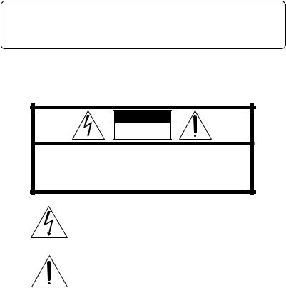
CAUTION
RISK OF ELECTRIC SHOCK
DO NOT OPEN
CAUTION: TO REDUCE THE RISK OF ELECTRIC SHOCK.
DO NOT REMOVE COVER (OR BACK).
NO USER-SERVICEABLE PARTS INSIDE.
REFER SERVICING TO QUALIFIED SERVICE PERSONNEL.
The lightning flash with arrowhead symbol, within an equilateral triangle, is intended to alert the user to the presence of uninsulated “dangerous voltage” within the product’s enclosure that may be of sufficient magnitude to constitute a risk of electric shock to persons.
The exclamation point within an equilateral triangle is intended to alert the user to the presence of important operating and maintenance (servicing) instructions in the literature accompanying the appliance.
|
-HA |
5 |
RF100S(J) |
|
6
CAUTION
To reduce the risk of electrical shocks, fire, etc.:
1.Do not remove screws, cover or cabinet.
2.Do not expose this appliance to rain or moisture.
IMPORTANT
1.Installation
●Select a place which is level, dry and neither too hot nor too cold (between 0°C and 35°C /32°F and 95°F).
●Keep away from direct sunlight.
●Do not put it too close to a heater.
2.Power cord
●Do not handle the power cord with wet hands!
●Do not bend the power cord sharply.
3.Malfunctions, etc.
●There are no serviceable parts inside. If anything goes wrong, unplug the power cord and consult your dealer.
●Do not insert any metallic object.
●Do not allow water to get inside.
4.Handling
●Be sure to use headphones and/or speakers together with the transmitter.
FEATURES
●Frequency modulation system which allows headphones/speakers to be used even in areas where the transmitter cannot be seen
●Extended Reception Range (up to 150 ft (46 m): using JVC measurements system)
●All-in-One package (transmitter, headphones and two speakers included)
●Volume controllable speaker with auto tuning function/bass boost control
●Auto-level control that automatically adjusts signals to the appropriate modulation level (for transmitter)
●Compact speaker design for indoor/outdoor use (not water resistant)
●Rechargeable System with Ni-Cd Batteries Provided (for headphones)
●Soft Comfort-Fit Headband that adjusts easily when put on
●Automatic Power On/Off transmitter
●Large 100 mm dia. woofer drivers and 50 mm dia. tweeter drivers for high quality sound (for speakers)
●Large 40 mm dia. drivers for high quality sound (for headphones)
●Single Volume Control adjusts the volume level of the left and right channels simultaneously (for headphones)
●Adaptable to Any Audio/Visual Equipment
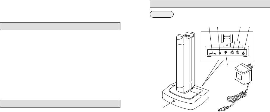
NAMES OF PARTS AND THEIR FUNCTIONS
Transmitter
|
3 |
|
|
|
|
|
|
1 2 |
|
[A] [B] |
|
|
|
||
4
 5
5
6
1TUNING (Tuning control)
Adjusts the transmission frequency.
2 CHG. (Charging output terminal)
3AUDIO (Audio input terminals)
[A]RCA pin jack (L/R)
[B]3.5 mm dia. stereo minijack
4 DC IN (DC 12 V jack)
5AC adaptor (J46598-001)
Connects to a household AC outlet (AC 120 V, 60 Hz).
6Indicator
When an audio signal is input : lights in green
When charging : lights in red
Notes:
●When an audio signal is input while charging, the indicator may light in orange.
●The provided AC adaptor is exclusively for use with this unit. Do not connect to any other equipment.
RF100S(J)-HA
6 |
7 |
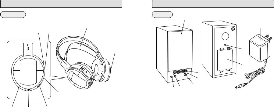
NAMES OF PARTS AND THEIR FUNCTIONS
Headphones
7
65
8
4
1 2 3
1ST. (Stereo signal indicator)
Lights in red when a signal is received from the transmitter.
2TUNING (Tuning control)
Adjusts the reception frequency.
3Volume control
Adjusts the volume level of the left and right channels simultaneously.
4CHARGE (Charging input terminal)
5 ON/OFF (Power switch)
6Power indicator
Lights in red when the power is turned on.
7 Soft Comfort-Fit Headband
8 Battery compartment cover
8
7
NAMES OF PARTS AND THEIR FUNCTIONS
Speakers
1
0

 9
9
7
8
|
2 |
|
3 |
6 5 |
4 |
|
1SPEAKER COVER
Can also be detached.
2POWER (Power indicator)
Lights in red when the power is turned on.
3STEREO (Stereo signal indicator)
Lights in green when receiving the signal from the transmitter.
Note:
The indicator also lights in green with signals not originating from the transmitter.
4VOLUME (Volume and power ON/OFF)
Turn the knob clockwise to turn the power on and to turn up the volume.
5AUTO TUNING
Adjusts the reception frequency. When the button is pressed, frequency tuning starts automatically and it stops when a signal is detected.
Note:
Signals not originating from the transmitter or unexpected signals can also cause the frequency tuning to stop. If this happens, press the button again to resume tuning.
6BASS BOOST CONTROL
Press this button to emphasize the bass.
7 DC IN (DC 9 V jack)
8 Battery compartment cover
9L/R (Channel marking)
Refer to this mark to set the speaker.
0AC adaptor (J46906-001)
Connects to a household AC outlet. (AC 120 V, 60 Hz)
9
RF100S(J)-HA

8
CONNECTION
How to connect to AV equipment
Connection to HEADPHONES jack
When connecting to a standard stereo phone jack (6.3 mm dia.)
—Use the provided plug adaptor (Converts a stereo minijack to
a standard stereo phone jack) |
Provided |
|
connection cord |
TV, audio amplifier, VCR, tape deck, video disc player, etc.
To HEADPHONES jack
When |
R-channel |
|
connecting to a |
||
(red plug) |
||
stereo minijack |
||
|
||
|
L-channel (white plug) |
When connecting to a monaural minijack
—Use an optional plug adaptor (Converts a stereo minijack to a monaural minijack)
To the audio input terminal [A]
Connection to LINE OUT or REC OUT terminals |
|
|
|
R-channel |
|
|
(red plug) |
|
TV, audio |
Provided connection cord |
|
amplifier, VCR, |
|
|
|
|
|
tape deck, video |
|
To the audio |
disc player, etc. |
|
|
|
input terminal [B] |
|
|
L-channel |
|
To LINE OUT or |
|
|
(white plug) |
|
|
REC OUT terminals |
|
|
10 |
|
|
CONNECTION
Connection to power supply
Caution:
The AC adaptors for the speakers are also provided in this unit. Be careful not to use them as the power supply for the transmitter. Misuse of the adaptor may result in fire, malfunction, etc., as the voltage and current value differ depending on the adaptor type.
To AC outlet (AC 120 V, 60 Hz)
Note:
Be sure to use the provided exclusive AC adaptor (J46598-001) for connection. Use of any other AC adaptor may cause a malfunction.
Provided exclusive AC adaptor (J46598-001)
Plug polarities
To DC IN 12 V jack
RANGE OF USE
150 ft
The usable area between the transmitter and the headphones is within a radius of approx. 150 ft (based on measurements taken when placed in direct view in a straight line).
Note:
The usable area may differ depending on building structure, etc. The range becomes shorter in the following cases:
In places such as inside an apartment with |
When items such as metal |
reinforced concrete walls, or when the |
furniture are situated nearby. |
transmitter and headphones are separated |
|
by obstacles such as steel-reinforced doors. |
|
●Be sure to keep this unit more than 50 cm away from concrete walls, metal furniture, etc.
11
RF100S(J)-HA
POWER REQUIREMENTS OF HEADPHONES
Use two exclusive rechargeable Ni-Cd batteries to power the headphones. When you purchase this unit, be sure to charge the provided rechargeable Ni-Cd batteries according to the following procedures before use.
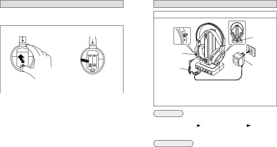
1. Insert the rechargeable Ni-Cd batteries
|
|
|
|
|
|
|
|
|
|
|
|
|
|
|
|
|
|
|
|
|
|
|
|
|
|
|
|
|
|
|
|
|
|
|
|
|
|
|
|
|
|
|
|
|
|
|
|
|
|
|
|
|
|
|
|
|
|
|
|
|
|
|
|
|
1 Remove the battery compartment cover |
2 Insert the two rechargeable Ni-Cd |
|||||||||||
on the right side of headphones. |
batteries with the polarities correctly |
|||||||||||
|
|
|
positioned. |
|||||||||
|
|
|
|
|
|
|
|
|
|
|
|
|
Cautions about the batteries
If the batteries are used incorrectly, they may leak, heat or explode, and may cause fire, injury or soiling. Make note of the following:
1.Be sure to use the provided exclusive Ni-Cd batteries. Do not use any other rechargeable Ni-Cd battery or dry cell battery.
2.Insert batteries with the (+) and (–) polarities correctly positioned, following the indications on the equipment.
3.Do not use a new battery with an old one, and do not use batteries holding different amounts of charge together.
4.Do not throw batteries in a fire or heat them.
5.Do not short-circuit the positive (+) and negative (–) terminals. Also, do not carry or store them with small metallic objects such as necklaces or coins.
6.Do not deform, take apart, modify or directly solder the batteries.
7.Do not remove or damage the covering tube.
8.If you notice phenomena that has never happened before, such as leakage, color change or deformity, stop using the batteries.
9.If any liquid from the batteries gets into your eyes, it may cause blindness. If battery liquid does get into your eyes, do not rub them, but instead immediately wash them thoroughly with clean water, then consult a doctor at once. Also, should any liquid from the
rechargeable batteries get onto your skin or clothes, it may burn your skin. In this case, wash with clean water immediately.
10.Do not immerse or wet the batteries in water.
11.Do not use or leave the batteries in an area where the temperature becomes significantly higher, such as in direct sunlight, inside a car on a hot day or near heat-generating equipment.
12.Do not subject the batteries to strong shocks or throw them.
13.Be sure to read the cautions on the batteries.
12
9
POWER REQUIREMENTS OF HEADPHONES
2. Charging rechargeable Ni-Cd batteries
F |
4 |
E |
|
F |
|
O |
|
N |
|
O |
|
G |
|
R |
|
A |
|
H |
|
C |
|
1
To charging input terminal
To AC outlet
2 |
3 |
|
|
||
To CHG. (charging |
To DC IN 12V jack |
|
output terminal) |
||
|
1 Set the ON/OFF (power) switch on the headphones to OFF.
The batteries cannot be charged when the switch is set to ON.
2 Connect the transmitter and the headphones with the provided cord for charging. 3 Connect the AC adaptor to the transmitter.
4 Plug the AC adaptor into an AC outlet. The charger starts charging the batteries automatically and the transmitter’s indicator lights in red.
Charging time
|
|
Quick charging |
Normal charging |
||||||
|
Charging starts |
(2 ~ 4 hours) |
|
Quick charging |
(Approx. 15 hours) |
Full charging |
|
||
|
|
|
|
|
|
|
|||
|
|
|
ends |
|
|
|
|
||
|
|
|
|
|
|
|
|
|
|
|
|
|
|
|
|
|
|
|
|
The transmitter's indicator |
The transmitter's indicator |
After full charging is complete, |
|||||||
lights in light red. |
changes to dark red. |
|
the transmitter's indicator |
||||||
|
|
|
|
|
|
continues to light in dark red. |
|||
Battery running time
After charging is complete, you can use them continuously for the following amounts of time:
Quick charging (2 ~ 4 hours) : 4 ~ 9 hours Full charging (19 hours) : 13 hours
Tips for better use
●Be sure to charge the batteries within the temperature range of 10° C ~ 35° C (50 °F ~ 95 °F ).
●Charging batteries that are not completely exhausted will cause efficiency to decline. Be sure to charge them after they have been completely exhausted.
13
RF100S(J)-HA
Loading...