


HD MEMORY CARD CAMERA RECORDER
GY-HM890U/GY-HM890E GY-HM890CHU/GY-HM890CHE GY-HM850U/GY-HM850E GY-HM850CHU/GY-HM850CHE
INSTRUCTIONS
In this illustration, the supplied viewfinder, microphone, and lens are attached to the GY-HM890U/GY-HM890E.
The lens is not supplied for GY-HM890CHU/GY-HM890CHE and GY-HM850CHU/GY-HM850CHE. The specifications and appearance of this product are subject to changes for further improvement without prior notice.
Please check the latest version of the INSTRUCTIONS from the following Mobile User Guide, or download the PDF from the URL below.
Mobile User Guide
When you are outside, you can refer to the instructions from your Android phone or iPhone. http://manual3.jvckenwood.com/pro/mobile/global/
You can view the Mobile User Guide using the browser on your Android phone or iPhone.
For Customer Use:
Enter below the Serial No. which is located on the body.
Retain this information for future reference.
Model No. GY-HM890U / GY-HM890CHU
GY-HM850U / GY-HM850CHU
Serial No.
Ver. 1.00
Please read the following before getting started:
Thank you for purchasing this JVC product. Before operating this unit, please read the
instructions carefully to ensure the best possible performance.
In this manual, each model number is described without the last letter (U/E) which
means the shipping destination.
(U: for USA and Canada, E: for Europe) Only “U” models (GY-HM890U/GY-HM890CHU/
GY-HM850U/GY-HM850CHU) have been evaluated by UL.
LST1584-001A
2

Safety Precautions
IMPORTANT SAFEGUARDS
1.Read all of these instructions.
2.Save these instructions for later use.
3.All warnings on the product and in the operating instructions should be adhered to.
4.Unplug this appliance system from the wall outlet before cleaning. Do not use liquid cleaners or aerosol cleaners.
Use a damp cloth for cleaning.
5.Do not use attachments not recommended by the appliance manufacturer as they may cause hazards.
6.Do not use this appliance near water - for example, near a bathtub, washbowl, kitchen sink, or laundry tub, in a wet basement, or near a swimming pool, etc.
7.Do not place this
appliance on an unstable cart, stand, or table. The appliance may fall, causing serious injury
to a child or adult, and serious damage to the appliance. Use only with a cart or stand recommended by the manufacturer, or sold with the appliance. Wall or shelf mounting should follow the manufacturer’s instructions, and should use a mounting kit approved by the manufacturer. An appliance and cart combination should be moved with care. Quick stops, excessive force, and uneven surfaces may cause the appliance and cart combination to overturn.
8.Slots and openings in the cabinet and the back or bottom are provided for ventilation, and to insure reliable operation of the appliance and to protect it from overheating, these openings must not be blocked or covered. The openings should never be blocked by placing the appliance on a bed, sofa, rug, or other similar surface. This appliance should never be placed near or over a radiator or heat register. This appliance should not be placed in a built-in installation such as a bookcase unless proper ventilation is provided.
9.This appliance should be operated only from the type of power source indicated on the marking label. If you are not sure of the type of power supplied to your home, consult your dealer or local power company. For appliance designed to operate from battery power, refer to the operating instructions.
10.For added protection for this product during a lightning storm, or when it is left unattended and unused for long periods of time, unplug it from the wall outlet and disconnect the antenna or cable system. This will prevent damage to the product due to lightning and power-line surges.
11.Do not allow anything to rest on the power cord. Do not locate this appliance where the cord will be abused by persons walking on it.
12.Follow all warnings and instructions marked on the appliance.
13.Do not overload wall outlets and extension cords as this can result in fire or electric shock.
14.Never push objects of any kind into this appliance through cabinet slots as they may touch dangerous voltage points or short out parts that could result in a fire or electric shock. Never spill liquid of any kind on the appliance.
Introduction
Safety Precautions |
3 |
Introduction
15.Do not attempt to service this appliance yourself as opening or removing covers may expose you to dangerous voltage or other hazards. Refer all servicing to qualified service personnel.
16.Unplug this appliance from the wall outlet and refer servicing to qualified service personnel under the following conditions:
a.When the power cord or plug is damaged or frayed.
b.If liquid has been spilled into the appliance.
c.If the appliance has been exposed to rain or water.
d.If the appliance does not operate normally by following the operating instructions. Adjust only those controls that are covered by the operating instructions as improper adjustment of other controls may result in damage and will often require extensive work by a qualified technician to restore the
appliance to normal operation.
e.If the appliance has been dropped or the cabinet has been damaged.
f.When the appliance exhibits a distinct change in performance - this indicates a need for service.
17.When replacement parts are required, be sure the service technician has used replacement parts specified by the manufacturer that have the same characteristics as the original part. Unauthorized substitutions may result in fire, electric shock or other hazards.
18.Upon completion of any service or repairs to this appliance, ask the service technician to perform routine safety checks to determine that the appliance is in safe operating condition.
FOR USA AND CANADA
CAUTION
RISK OF ELECTRIC
SHOCK
DO NOT OPEN
CAUTION:
TO REDUCE THE RISK OF ELECTRIC SHOCK.
DO NOT REMOVE COVER (OR BACK).
NO USER-SERVICEABLE PARTS INSIDE. REFER SERVICING TO QUALIFIED SERVICE PERSONNEL.
The lightning flash with arrowhead symbol, within an equilateral triangle is intended to alert the user to the presence of uninsulated “dangerous voltage” within the product’s enclosure that may be of sufficient magnitude to constitute a risk of electric shock to persons.
The exclamation point within an equilateral triangle is intended to alert the user to the presence of important operating and maintenance (servicing) instructions in the literature accompanying the appliance.
CAUTION:
CHANGES OR MODIFICATIONS NOT APPROVED BY JVC COULD VOID USER’S AUTHORITY TO OPERATE THE EQUIPMENT.
4 Safety Precautions

Information for USA
This device complies with part 15 of the FCC Rules. Changes or modifications not approved by JVC KENWOOD could void the user's authority to operate the equipment.
This equipment has been tested and found to comply with the limits for a Class A digital device, pursuant to Part 15 of the FCC Rules. These limits are designed to provide reasonable protection against harmful interference when the equipment is operated in a commercial environment. This equipment generates, uses, and can radiate radio frequency energy and, if not installed and used in accordance with the instruction manual, may cause harmful interference to radio communications. Operation of this equipment in a residential area is likely to cause harmful interference in which case the user will be required to correct the interference at his own expense.
This device complies with Part 15 of the FCC Rules.
Operation is subject to the following two conditions: (1)This device may not cause harmful interference, and (2) this device must accept any interference received, including interference that may cause undesired operation.
Due to design modifications, data given in this instruction book are subject to possible change without prior notice.
POUR CANADA
ATTENTION
RISQUE
D’ELECTROCUTION
NE PAS OUVRIR
ATTENTION:
POUR EVITER TOUT RISQUE D’ELECTROCUTION NE PAS OUVRIR LE BOITER. AUCUNE PIECE INTERIEURE N’EST A REGLER PAR L’UTILISATEUR. SE REFERER A UN AGENT QUALIFIE EN CAS DE PROBLEME.
Le symbole de l’éclair à l’intérieur d’un triangle équilatéral est destiné à alerter l’utilisateur sur la présence d’une “tension dangereuse” non isolée dans le boîtier du produit. Cette tension est suffisante pour provoquer l’électrocution de personnes.
Le point d’exclamation à l’intérieur d’un triangle équilatéral est destiné à alerter l’utilisateur sur la présence d’opérations d’entretien importantes au sujet desquelles des renseignements se trouvent dans le manuel d’instructions.
Ces symboles ne sont utilisés qu’aux Etats-Unis.
CAN ICES-3 A / NMB-3 A
The apparatus shall not be exposed to dripping or splashing and that no objects filled with liquids, such as vases, shall be placed on the apparatus.
Introduction
Safety Precautions |
5 |

|
|
WARNING: |
|
|
|
TO PREVENT FIRE OR SHOCK |
|
|
|
HAZARD, DO NOT EXPOSE THIS |
|
|
|
UNIT TO RAIN OR MOISTURE. |
|
|
|
CAUTION: |
|
Introduction |
|||
This unit should be used with 12V DC only. |
|||
|
|
To prevent electric shocks and fire hazards, |
|
|
|
do NOT use anyother power source. |
|
|
|
|
|
|
|
|
|
|
|
AVERTISSEMENT : |
|
|
|
POUR EVITER LES RISQUES |
|
|
|
D’INCENDIE OU D’ELECTROCUTION, |
|
|
|
NE PAS EXPOSER L’APPAREIL A LA |
|
|
|
PLUIE NI A L’HUMIDITE. |
|
|
|
ATTENTION: |
|
|
|
Ce magnétoscope ne doit être utilisé que |
|
|
|
sur du courant direct en 12V. |
|
|
|
Afin d’eviter tout resque d’incendie ou |
|
|
|
d’electrocution, ne pas utillser d’autres |
|
|
|
sources d’alimentation électrique. |
|
|
|
|
|
|
|
|
|
|
|
NOTE: |
|
|
|
The rating plate and safety caution are |
|
|
|
on the bottom and/or the back of the |
|
|
|
main unit. |
|
|
|
REMARQUE : |
|
|
|
La plaque d’identification et |
|
|
|
l’avertissement de sécurité se trouvent |
|
|
|
sous l’appareil et/ou au dos. |
|
|
|
|
|
|
|
|
|
|
|
CAUTION: |
|
|
|
To prevent electric shock, do not open |
|
|
|
the cabinet. |
|
|
|
No user serviceable parts inside. Refer |
|
|
|
servicing to qualified service personnel. |
|
|
|
|
|
|
|
FOR EUROPEAN |
|
|
|
|
|
|
|
WARNING |
|
|
|
This is a Class A product. In a domestic |
|
|
|
environment this product may cause radio |
|
|
|
interference in which case the user may |
|
|
|
be required to take adequate measures. |
|
|
|
|
|
|
|
|
|
|
|
The plastics packaging bags may cause |
|
|
|
suffocation when they are covered over the |
|
|
|
head. Tear them open, and keep them away |
|
|
|
from the reach of infants and children by |
|
|
|
ensuring that they are disposed of properly. |
|
|
|
|
|
Dear Customer
This apparatus is in conformance with the valid European directives and standards regarding electromagnetic compatibility and electrical safety. European representative of
JVC KENWOOD Corporation is:
JVC Technical Services Europe GmbH Konrad-Adenauer-Allee 1-11
61118 Bad Vilbel Germany
Sehr geehrter Kunde, sehr geehrte Kundin, dieses Gerät stimmt mit den gültigen europäischen Richtlinien und Normen bezüglich elektromagnetischer Verträglichkeit und elektrischer Sicherheit überein.
Die europäische Vertretung für die JVC KENWOOD Corporation ist:
JVC Technical Services Europe GmbH Konrad-Adenauer-Allee 1-11
61118 Bad Vilbel Deutschland
Manufacturer
3-12,Moriya-cyo,Kanagawa-ku, Yokohama-shi,
Kanagawa 221-0022,Japan
Importer (EU only)
JVC House
JVC Business Park
12 Priestley Way,London NW2 7BA,
United Kingdom
6 Safety Precautions

FOR EUROPE
0 This equipment is in conformity with the provisions and protection requirements of the corresponding European Directives. This equipment is designed for professional video appliances and can be used in the following environments:
Controlled EMC environment (for example, purpose-built broad-casting or recording studio), and rural outdoors environments.
In order to keep the best performance and furthermore for electromagnetic compatibility we recommend to use cables not exceeding the following lengths:
Terminal |
Cable |
Length |
[DC INPUT] |
Exclusive Cable |
5 m |
[VIDEO OUT] |
Coaxial Cable |
10 m |
[INPUT1/INPUT2] |
Shielded Cable |
3 m |
[AUDIO OUTPUT |
Shielded Cable |
10 m |
CH-1/3] |
|
|
[AUDIO OUTPUT |
Shielded Cable |
10 m |
CH-2/4] |
|
|
[AUX] |
Shielded Cable |
5 m |
[PHONES] |
Exclusive Cable |
3 m |
[HDMI] |
Shielded Cable |
3 m |
[HD/SD SDI |
Coaxial Cable |
10 m |
IN] AB |
|
|
[HD/SD SDI OUT] |
Coaxial Cable |
10 m |
[REMOTE1] |
Exclusive Cable |
5 m |
[REMOTE2] |
Exclusive Cable |
1 m |
[LENS] |
Unshielded |
0.1 m |
|
Cable |
|
[VF] |
Special cable |
0.3 m |
[DEVICE] |
Shielded Cable |
2 m |
[GENLOCK] |
Coaxial Cable |
10 m |
[TC IN] |
Coaxial Cable |
10 m |
[TC OUT] |
Coaxial Cable |
10 m |
[STUDIO] A |
Exclusive Cable |
0.3 m |
B |
|
|
o Para Brasil
Informação sobre eliminação de baterias
Este produto não deverá ser eliminado como lixo doméstico em geral. Devolva a bateria velha ao comerciante
ou para a rede autorizada, para que seja devolvida ao fabricante ou importador. A reciclagem e eliminação de lixo em uma maneira adequada, ajudarão para preservar recursos, prevenindo, ao
mesmo tempo, contra efeitos prejudiciais
sobre a nossa saúde e o meio ambiente.
.
Introduction
Caution:
Where there are strong electromagnetic waves or magnetism, for example near a radio or TV transmitter, transformer, motor, etc., the picture and the sound may be disturbed. In such case, please keep the apparatus away from the
. sources of the disturbance.
Safety Precautions |
7 |

Introduction
|
|
|
|
|
|
|
|
Qc |
Ih |
De |
Ds)WJ* |
)QCC* |
QCEF |
|
|
|
|
|
|
|
|
|
|
|
|
|
|
|
|
|
|
|
|
|
|
|
|
|
|
|
|
|
|
|
|
|
|
|
|
|
|
|
|
|
|
!HC0U37683.3122!
! |
! |
HC0U37683.3122!
8 Safety Precautions

Contents |
|
Introduction |
|
Safety Precautions ............................................ |
3 |
Contents ............................................................ |
9 |
Main Features ................................................. |
12 |
Precautions for Proper Use ............................. |
14 |
Operation Modes ............................................. |
18 |
Names of Parts ................................................ |
20 |
Side Control Panel ....................................... |
22 |
Viewfinder .................................................... |
23 |
LCD Monitor ................................................ |
24 |
Side Terminal Section .................................. |
24 |
SD Slot ......................................................... |
25 |
Rear Terminal .............................................. |
25 |
Lens Section AC................................ |
26 |
Basic System Diagram .................................... |
27 |
Preparations |
|
Settings and Adjustments Before Use ............. |
28 |
Attaching the Lens (Supplied) ...................... |
28 |
Adjusting the Grip Belt AC................. |
28 |
Attaching the Microphone (Supplied) ........... |
28 |
Attaching the Viewfinder (Supplied) ............. |
28 |
Opening/Closing the Lens Cover AC. 29 |
|
Attaching/Detaching the Hood AC..... 29 |
|
Attaching the Anti-reflective Film .................. |
30 |
Power Supply .................................................. |
30 |
Using AC Power (DC IN Power) ................... |
30 |
Using a Battery Pack .................................... |
31 |
Power Status Display ...................................... |
32 |
Turning On/Off the Power ................................ |
33 |
Initial Settings .................................................. |
34 |
Displays on the LCD Monitor and Viewfinder .. |
36 |
Display Screen ............................................. |
36 |
Status Screen .............................................. |
37 |
USB Mode Screen ....................................... |
38 |
Remote Edit Mode Screen ........................... |
38 |
Warning Display ........................................... |
38 |
Adjusting the LCD Monitor and Viewfinder ...... |
38 |
Adjusting the LCD Monitor ........................... |
39 |
Adjusting the Viewfinder .............................. |
40 |
Adjusting the Monitor Speaker ........................ |
40 |
Adjusting Back Focus ...................................... |
41 |
Assignment of Functions to User Buttons ........ |
42 |
Tally Lamp ....................................................... |
42 |
SD Card ........................................................... |
43 |
Usable Cards ............................................... |
43 |
Formatting (Initializing) SD Cards ................ |
45 |
Restoring and Updating the SD Card ........... |
46 |
Clips Recorded to SD Cards ........................ |
47 |
About the Operation Lock Feature ................... |
48 |
Shooting
Basic Shooting Procedures ............................. |
49 |
Introduction |
Selecting a Recording Format ......................... |
50 |
|
Adjusting the Brightness .................................. |
57 |
|
Zoom Operation .............................................. |
52 |
|
Focus Operation F.................................... |
53 |
|
Adjusting the Focus by Face Detection F. 56 |
|
|
Adjusting the Iris .............................................. |
58 |
|
Setting the Gain ............................................... |
59 |
|
Setting the Electronic Shutter .......................... |
60 |
|
Setting the ND Filter ........................................ |
62 |
|
Adjusting the White Balance ............................ |
63 |
|
Adjusting the Camera Image ........................... |
68 |
|
Using the Image Stabilizer F..................... |
68 |
|
Audio Recording .............................................. |
69 |
|
Audio Output during Recording ....................... |
72 |
|
Time Code and User’s Bit ................................ |
72 |
|
Setting Time Code Generator .......................... |
73 |
|
Setting the User’s Bit ....................................... |
76 |
|
Synchronizing the Time Code with an External |
78 |
|
Time Code Generator ...................................... |
|
|
Setting Zebra Pattern ...................................... |
79 |
|
Setting Spot Meter ........................................... |
80 |
|
Acquiring Positioning Information by GPS ....... |
82 |
|
Viewing Recorded Videos Immediately (Clip |
83 |
|
Review) ........................................................... |
|
|
Using the Histogram ........................................ |
84 |
|
Recording Simultaneously at Two Different |
84 |
|
Definitions ....................................................... |
|
|
Splitting the Clips Freely (Clip Cutter Trig) ....... |
85 |
|
Dual Rec .......................................................... |
85 |
|
Backup Rec ..................................................... |
87 |
|
Special Recording ........................................... |
89 |
|
Pre Rec ........................................................ |
89 |
|
Clip Continuous Rec .................................... |
89 |
|
Frame Rec ................................................... |
91 |
|
Interval Rec .................................................. |
92 |
|
Variable Frame Rec ..................................... |
93 |
|
Playback |
|
|
Playing Recorded Clips ................................... |
94 |
|
Thumbnail Screen ........................................ |
94 |
|
Actions ......................................................... |
96 |
|
Playing back ................................................ |
97 |
|
Deleting Clips .................................................. |
98 |
|
Appending/Deleting OK Mark .......................... |
99 |
|
Contents |
9 |
|

Introduction
Selecting and Performing Operations on Multiple |
|
Clips .............................................................. |
100 |
Selecting Multiple Clips Randomly ............. |
100 |
Selecting Multiple Clips Consecutively ...... |
101 |
Trimming Recorded Clips .............................. |
102 |
Menu Display and Detailed Settings |
|
Basic Operations in Menu Screen ................. |
103 |
Display...................................................................and Description of the Menu Screen104 |
|
Text Input with Software Keyboard ............ |
105 |
About the Menu Lock Feature ....................... |
106 |
Menu Screen Hierarchical Chart ................... |
107 |
Camera Function Menu ................................. |
108 |
User Switch Set Item .................................. |
111 |
FULL AUTO Item ....................................... |
113 |
Camera Process Menu .................................. |
114 |
Detail/Adjust Item ....................................... |
117 |
White Balance Item .................................... |
118 |
TC/UB Menu ................................................. |
119 |
LCD/VF Menu ................................................ |
120 |
Shooting Assist Item .................................. |
121 |
Marker Settings Item .................................. |
121 |
Display Settings Item ................................. |
122 |
A/V Set Menu ................................................ |
125 |
Video Set Item ........................................... |
125 |
Audio Set Item ........................................... |
127 |
System Menu ................................................ |
130 |
Record Set Item ......................................... |
132 |
Network/Settings Item ................................ |
137 |
Adding/Editing Frequently Used Menu Items |
142 |
Registration to Favorites Menu .................. |
142 |
Editing Favorites Menu .............................. |
143 |
Display/Status Screen |
|
Display Screen in Camera Mode ................... |
145 |
Display Screen in Media Mode ...................... |
151 |
Status Screen ................................................ |
153 |
Camera Features |
|
Marker and Safety Zone Displays .................. |
154 |
Smoothening the Skin Color (Skin Detail |
|
Function) ....................................................... |
155 |
Color Bar Output ........................................... |
155 |
Adjusting Color Matrix ................................... |
156 |
Configuring Setup Files ................................. |
157 |
Saving Setup Files ..................................... |
157 |
Loading a Setup File .................................. |
158 |
Deleting Setup Files ................................... |
159 |
Connecting External Devices |
|
Managing/Editing Clips on a PC .................... |
160 |
10 Contents |
|
Connecting External Monitor ......................... |
161 |
Connecting a Earphone ................................. |
163 |
Connecting Wired Remote Control ................ |
164 |
Connecting a Remote Control Unit ................ |
164 |
Functions Operable from the Remote Control Unit |
|
....................................................................... |
166 |
Inputting SDI Signals from an External Device A |
|
B............................................................ |
168 |
Inputting External Synchronizing Signals |
|
(Genlock) ....................................................... |
169 |
Displaying Return Videos from an External Device |
|
AB.................................................... |
172 |
Studio System AB............................ |
172 |
Connecting to the Network |
|
Functions of Network Connection .................. |
174 |
Preparing Network Connection ...................... |
174 |
Operating Environment .............................. |
174 |
Camera Setup for Network Connection ..... |
175 |
Connecting via Wireless LAN .................... |
175 |
Connecting via Wired LAN ......................... |
177 |
Connecting via Cellular Adapter ................ |
177 |
Importing Metadata ....................................... |
178 |
Preparing Metadata ................................... |
178 |
Configuring the Server for Downloading .... |
178 |
Importing Metadata .................................... |
179 |
Uploading a Recorded Video Clip ................. |
180 |
Configuring the FTP Server for Uploading . 180 |
|
Uploading Video Clip ................................. |
180 |
Connecting from a Web Browser ................... |
182 |
Editing Metadata ........................................... |
183 |
Planning Metadata ..................................... |
183 |
Clip Metadata ............................................ |
184 |
Uploading a Recording Clip via a Web Browser |
|
....................................................................... |
187 |
View Remote Feature .................................... |
190 |
Operating Procedure ................................. |
190 |
Registering/Deleting Preset Zoom ............. |
191 |
Camera Control Function .............................. |
193 |
Changing the Settings via a Web Browser .... |
194 |
Changing View Remote Function Settings . 195 |
|
Changing Connection Setup ...................... |
196 |
Changing Metadata Server Settings .......... |
197 |
Changing Clip Server Settings ................... |
197 |
Changing Streaming Settings .................... |
197 |
Managing the Network Connection Settings File |
|
....................................................................... |
197 |
Saving the Connection Settings File .......... |
197 |
Reading the Connection Settings File ........ |
198 |
Deleting Connection Settings .................... |
199 |
Performing Live Streaming ............................ |
199 |
Setting Distribution ..................................... |
200 |
Starting Distribution ................................... |
200 |
Others |
|
Error Messages and Actions ......................... |
202 |
List of FTP Transfer Errors ......................... |
203 |
List of Live Streaming Error Displays ......... |
205 |
Blinking of the Tally Lamp .......................... |
206 |
Warning Tone ............................................ |
206 |
Troubleshooting ............................................ |
206 |
Specifications ................................................ |
209 |
Index ............................................................. |
214 |
Software License Agreement ........................ |
216 |
Important Notice concerning the Software ..... |
217 |
Open Source License .................................... |
218 |
Introduction
Contents 11

Introduction
Main Features
Inheriting the compact shoulder-carry style
Inheriting the compact shoulder-carry style of the GY-HM700 series, this camera recorder enables more stable shooting while maintaining the same weight as handheld models.
F11 Sensitivity, 1/3-inch Full HD 3CMOS Sensors
This camera recorder is equipped with three 1/3- inch 2.07M pixels full HD CMOS sensors.
It delivers high image quality with a high color resolution through the processing of individual R, G, B color signals. 12-bit signal processing and the new 2D DNR removes dark current and optical shot noise without losing S/N and high resolution, thereby achieving high F11 sensitivity.
Equipped with the newly-developed Fujinon 20x interchangeable zoom lens with AF/OIS AC
It ensures high magnification of 29 mm at wide ends, and provides high sensitivity across all regions with F1.6-3.0.
This interchangeable lens comes with an autofocus (AF) and Optical Image Stabilizer (OIS) function, allowing for stable focusing when used as a shoulder-carry camera recorder.
In addition to the central area, it also comes with a face-detection autofocus feature, and supports switching to manual focusing.
The zoom ring with zoom ring pin enables zooming from the wide end to the tele end in 90 degrees. Focus and iris control are also possible using separate rings.
4-position ND Filter
This camera recorder incorporates three types of ND filters.
Adjust the amount of light according to the brightness during shooting by switching the 4- position ND filter (OFF, 1/4, 1/16, 1/64).
JVC’s Proprietary FALCONBRID HighQuality Imaging Engine
The FALCONBRID high-quality imaging engine omits unnecessary processing through incorporating camera processing and image compression on a single chip. Images from imaging devices are compressed and processed without any loss thereby achieving high-quality images.
MPEG2 and H.264 Codec
FALCONBRID allows users to select a recording format such as MPEG-2, H.264 and AVCHD Progressive, the most commonly used codec for professional videos.
50 Mbps high-resolution recording mode
This camera recorder comes with a 50 Mbps mode in the H.264 format (1920x1080: MOV) to support high-resolution video recording.
QuickTime (MPEG-2 HD/H.264 HD/ H.264 SD)/MP4 (MPEG-2 HD)/AVCHD File Formats
Inheriting the concept of ProHD memory camera recorders, this camera recorder also supports various file formats, such as AVCHD and QuickTime (H.264 SD) files, as well as QuickTime (MPEG-2 HD/H.264 HD) files that can be directly edited on Apple Final Cut Pro, in addition to MP4 files that are most suitable for XDCAM EX Nonlinear Editing Workflow.
Two SDHC/SDXC Card Slots for Dual, Backup and Series Recording
The most common SDHC/SDXC card recording system is used as the memory card.
This ensures reliability and operation at low running cost.
Various user friendly recording systems are also available. These include dual recording of the same file to two cards, and using REC/STBY to break up video clips in one card while performing backup recording to the other card.
Diverse simultaneous recording combinations (HD and SD, HD and Proxy Video, etc.)
This camera recorder is equipped with a proxy video (960x540: MOV, 480x270: MOV, 1440x1080: AVCHD) recording function that is convenient for network distribution.
Further enhancements were made to the dual recording feature, allowing for HD recording to one of the SDHC/SDXC cards, and SD or proxy video recording to the other card at the same time.
12 Main Features

Variable frame recording
Enables beautiful slow motion and quick motion image recording such as overcrank and undercrank.
Th ability to change the frame rate during recording enables quick to gradually slow motion effects.
Pre Rec function (up to 10 seconds) and Interval Rec function
SDI/HDMI Simultaneous Output
Equipped with both [HD/SD SDI] and [HDMI]
terminals as digital output.
Non-compressed full HD video signals and audio signals can be output to the [HD/SD SDI] and
[HDMI] terminals at the same time.
Comes with genlock input and time code input/output terminals
This camera recorder supports the use of multiple cameras as well as studio use.
Professional Switch Layout and Various Video Parameter Settings
Switches for Gain and White Balance are available on the side panel to enable quick switching according to the shooting scene.
Image parameters such as gamma and color matrixes are also available in the menu for adjusting preferred tones.
0.45-inch 1.22-megapixel color viewfinder, 4.3-inch 1.15-megapixel LCD display
(Equipped with Focus Assist function) 4-channel audio
Supports 4-channel audio in the MPEG-2/H.264 recording mode.
In addition to two mic inputs, you can also record audio input from the [AUX] input terminal to an
independent track.
2-channel XLR audio input (microphone/line switch, phantom power supply) and mini jack input terminal for wireless microphone receiver
Supports two types of wired remote control units
In addition to JVC’s original 6-pin remote terminal, this camera recorder is also equipped with a φ2.5mm stereo jack remote control terminal.
Built-in GPS
This camera recorder is built in with a GPS function, which enables the positional information obtained from the GPS satellite during a shoot to be recorded as metadata.
*Note that acquisition of the positional information may fail depending on the weather condition.
Diverse Network Functions
This camera recorder supports functions such as remote control from a mobile device, viewing, metadata transmission, and proxy file transfer as an FTP client.
Equipped with a USB host function, you can upload recorded files stored in this unit via a network by connecting it to network devices such as a wireless LAN adapter (optional). Video and audio streaming is also supported.
Professional-spec battery
This camera recorder supports the use of batteries used by broadcasting stations, such as Anton/ Bauer and IDX batteries.
(Gold Mount: For use with Anton/Bauer battery (U model), V Mount: For use with IDX battery (E model))
Application Software Provided
The [JVC ProHD Clip Manager] application
software is provided for you to copy recorded clips to Windows or Macintosh computers and for checking the video images. (For MP4 file format)
The disc provided with this camera recorder comes with [JVC ProHD Clip Manager] and other
application software as well as their user guides.
*For details, refer to the user guides for each application software.
Introduction
Main Features 13

Introduction
|
|
|
|
Precautions for Proper |
|||
|
|
|
Content of this manual |
||||
Symbols used |
Use |
||||||
Caution |
: |
Describes precautions concerning the |
|
|
|
||
|
|
|
operation of this product. |
|
Storage and Usage Locations |
||
|
|
|
|
||||
Memo |
: |
Describes reference information, such as |
|
||||
|
|
|
functions and usage restrictions of this |
o Allowable ambient temperature and humidity |
|||
A |
|
|
product. |
Be sure to use this unit within the allowable |
|||
|
: Indicates the reference page numbers and |
||||||
|
|
temperature range of 0 °C to 40 °C (32 °F to 104°F) |
|||||
A : |
reference items. |
||||||
Feature available on |
and a relative humidity of 35 % to 80 %. Using this |
||||||
B : |
GY-HM890U/GY-HM890E only. |
unit at a temperature or humidity outside the |
|||||
Feature available on |
allowable ranges could result not only in |
||||||
C : |
GY-HM890CHU/GY-HM890CHE only. |
malfunction but also serious impact on the CMOS |
|||||
Feature available on |
elements as small white spots may be generated. |
||||||
D : |
GY-HM850U/GY-HM850E only. |
Please exercise care during use. |
|||||
Feature available on |
o Strong electromagnetic waves or magnetism |
||||||
|
|
|
GY-HM850CHU/GY-HM850CHE only. |
Noise may appear in the picture or audio and/or the |
|||
F : Feature available only with the supplied |
|||||||
colors may be incorrect if this unit is used near a |
|||||||
|
|
|
lens. |
||||
Content of this manual |
radio or television transmitting antenna, in places |
||||||
where strong magnetic fields are generated by |
|||||||
0 |
All rights reserved by JVC KENWOOD Corporation. |
transformers, motors, etc., or near devices emitting |
|||||
|
Unauthorized duplication or reprinting of this |
radio waves, such as transceivers or cellular |
|||||
|
manual, in whole or in part, is strictly prohibited. |
phones. |
|||||
0 |
Illustrated designs, specifications and other |
o Use of wireless microphone near this unit |
|||||
|
contents of this manual are subject to change for |
When a wireless microphone or wireless |
|||||
0 |
improvement without prior notice. |
microphone tuner is used near this unit during |
|||||
AVCHD Progressive and the AVCHD Progressive |
recording, the tuner could pick up noise. |
||||||
|
|||||||
|
logo are trademarks of Panasonic Corporation and |
o Avoid using or placing this unit in the following |
|||||
|
Sony Corporation. |
places. |
|||||
0 |
XDCAM EX is a trademark of Sony Corporation. |
||||||
0 |
SDXC and SDHC logos are trademarks of SD-3C, |
0 |
Places subject to extreme heat or cold |
||||
|
LLC. |
|
|
|
0 Places with excessive dirt or dust |
||
0 |
HDMI (High-Definition Multimedia Interface) and |
0 |
Places with high humidity or moisture |
||||
|
1are trademarks of HDMI Licensing, |
|
0 Places subject to smoke or vapor such as near |
||||
|
|
|
a cooking stove |
||||
|
LLC. |
|
|
|
|
||
0 |
|
|
|
0 Places subject to strong vibrations or unstable |
|||
QuickTime, Final Cut Pro, iPhone, iPad, iPod touch, |
|
|
surfaces |
||||
|
iOS, Mac OS and Safari are trademarks of Apple |
|
0 In a parked car under direct sunlight or near a |
||||
|
Inc., registered in the U.S. and other countries. |
|
|
heater for long hours |
|||
0 |
Android and Google Chrome are trademarks |
|
|
||||
o Do not place this unit at places that are subject |
|||||||
|
and/or registered trademarks of Google Inc. |
||||||
|
to radiation or X-rays, or where corrosive gases |
||||||
0 |
QR Code is a registered trademark of Denso Wave |
||||||
|
Incorporated. |
occur. |
|||||
0 |
Dolby and the double-D symbol are trademarks of |
oProtect this unit from being splashed with water. |
|||||
|
Dolby Laboratories. |
(Especially when shooting in the rain) |
|||||
0 |
Microsoft, Windows, Windows XP, Windows Vista, |
o Protect this unit from getting wet when shooting |
|||||
|
Windows 7, Windows 8, and Internet Explorer are |
on a beach. In addition, salt and sand may adhere |
|||||
|
registered trademarks of Microsoft Corporation in |
to the body. Clean the unit after use. |
|||||
|
the United States and/or other countries. |
oProtect this unit against penetration of dust when |
|||||
0 |
Mozilla and Firefox are either trademarks or |
||||||
|
registered trademarks of Mozilla Foundation in the |
using it in a place subject to sandy dust. |
|||||
|
United States and/or other countries. |
|
|
|
|||
0 |
Intel Core 2 Duo is a trademark or registered |
|
|
|
|||
|
trademark of Intel Corporation or its subsidiaries in |
|
|
|
|||
|
the United States and other countries. |
|
|
|
|||
0 |
The company name of Fontworks, Fontworks, and |
|
|
|
|||
|
the name of the fonts are registered trademarks of |
|
|
|
|||
|
Fontworks Inc. |
|
|
|
|||
0 |
Other product and company names included in this |
|
|
|
|||
|
instruction manual are trademarks and/or |
|
|
|
|||
|
registered trademarks of their respective |
|
|
|
|||
|
companies. Marks such as ™ and ® have been |
|
|
|
|||
|
omitted in this manual. |
|
|
|
|||
14 Content of this manual

Transportation
Do not drop or hit this unit against a hard object when transporting.
Power Saving
When this unit is not in use, be sure to set the [POWER ON/OFF] switch to “OFF” in order to
reduce power consumption.
Maintenance
o Turn off the power before performing any maintenance.
o Wipe the external cabinet of the unit with a soft cloth. Do not wipe the body with benzene or thinner. Doing so may cause the surface to melt or turn cloudy. When it is extremely dirty, soak the cloth in a solution of neutral detergent, wipe the body with it, and then use a clean cloth to remove the detergent.
Batteries
o The batteries recommended for use with this camera recorder are as follows.
U model : Dionic90 (Anton/Bauer)
E model : Endura-HL9 (IDX)
o Please make use of one of the recommended batteries.
Heavy batteries may fall off if they are not used correctly.
Regular Inspection (Maintenance)
Under normal environment, dust will accumulate on the camera recorder when it is used over a long period. Dust may enter the camera recorder especially if it is used outdoors. This may affect the image and sound quality of the camera recorder. Check and replace the fan after every 9000 hours (suggested guideline).
You can check the usage time of the fan in [System] B [System Information] B [Fan Hour].
(A P132 [ Fan Hour ] )
If the fan is used for more than 9000 hours without replacement, “FAN MAINTENANCE REQUIRED”
will be displayed every time you turn on the power.
About GPS
o The GPS (Global Positioning System) satellites are managed by the Department of State of the U.S., and its precision may be altered intentionally. o Perform positioning at an unobstructed location with a clear view that is not indoors or blocked by trees.
o The time needed for obtaining the position information may be longer and variation may also be larger depending on the surrounding environment and time of day.
o This camera recorder uses the WGS 84 World Geodetic System.
oSignal from GPS satellites may be interrupted by communication signal from electronic devices such as mobile phones.
LCD Monitor and Viewfinder
o The LCD monitor and viewfinder screen are manufactured using high-precision technology. Black spots may appear on the LCD monitor and viewfinder screen, or red, blue, and/or white spots may not disappear. However, this is not a malfunction and these spots are not recorded on the SD card.
oIf you use this unit continuously for a long period of time, the characters displayed in the viewfinder may temporarily remain on the screen. This is not recorded on the SD card. They will not appear after you turn the power off and then on again.
o If you use this unit in a cold place, the images may appear to lag on the screen, but this is not a malfunction. Retained images are not recorded on the SD card.
o Do not press against the surface with force or subject it to strong impact. Doing so may damage or break the screens.
o Noise may appear in the viewfinder when switching between the live video and playback images.
oDue to the characteristic of the viewfinder display device, colors may appear on the images when you blink your eyes. It does not affect the recorded images, SDI output, or HDMI output.
Introduction
Precautions for Proper Use 15

Introduction
SDHC/SDXC Cards
o SDHC/SDXC card is referred to as “SD card” in this manual.
o This camera recorder saves the recorded images and audio sound on the SD card (sold separately) in the card slot.
o Use an SD card (4 GB to 128 GB) with Class 6 or higher performance, formatted using this camera recorder.
*Depending on the recording format, SD card with Class 4 or higher performance can also be used. Some recording formats supports only the use of cards with Class 10 or higher.
(A P50 [Selecting a Recording Format] )
*Using cards other than those from Panasonic, TOSHIBA or SanDisk may result in recording failure or data loss.
oIf the SD card contains files recorded by devices other than this camera recorder or files that are saved from a PC, the recordable time may be shorter or data may not be properly recorded. In addition, the remaining space on the card may not increase even when files are deleted using a PC.
Handling of SD Cards
o The status indicator lights up in red when data on the SD card is being accessed.
Do not remove the SD card during data access (such as recording, playback, or formatting). Do not turn off the power or remove the battery and AC adapter during access either.
oDo not use or store the SD card in a place that is subject to static electricity or electrical noise.
oDo not place the SD card near locations that are exposed to strong magnetic fields or radio waves. o Inserting the SD card incorrectly may result in damage of this unit or the SD card.
o We are not liable for any accidental loss of data stored on the SD card. Please back up any important data.
o Make use of the SD card within the prescribed conditions of use.
Do not use it at the following locations. Places that are subject to direct sunlight, high humidity or corrosion, places near thermal
equipment, sandy or dusty places, or in a car under the sun with the doors and windows closed.
oDo not bend or drop the SD card, or subject it to strong impact or vibration.
o Do not splash the SD card with water. o Do not dismantle or modify the SD card.
o Do not touch the terminals with your hands or with a metal object.
o Do not allow dust, dirt, water, or foreign objects to adhere to the terminals.
oDo not remove the labels or stick other labels or stickers on the SD cards.
o Do not use pencils or ballpoint pens to write on the SD cards. Always use oil-based pens.
o If you format (initialize) the SD card, all data recorded on the card, including video data and setup files, will be deleted.
o You are recommended to use cards that are formatted (initialized) on this camera recorder. 0 The SD card may be damaged if the camera recorder is not operated correctly. Formatting
(Initializing) the SD card may allow it to operate correctly.
0 SD cards that have been formatted (initialized) on other cameras, computers or peripheral equipment may not operate correctly. In this case, format (initialize) the SD card on this camera recorder.
o If you want to wipe out all information by completely erasing the data, we recommend either using commercially available software that is specially designed for that purpose, or by physically destroying the SD card with a hammer, etc. When formatting or erasing data using the camera recorder, only the file administration information is changed. The data is not completely erased from the SD card.
o Some commercially available SD cards may be harder to be removed from this unit. Remove them by hooking onto the groove on the cards.
0 It will be easier to remove the cards after several times.
0 Do not stick any stickers on the cards.
 Groove
o The SD card may pop out when it is being removed. Be careful not to lose the card.
16 Precautions for Proper Use

Copyright
Any recordings made on this camera recorder that are played back for profit or public preview may infringe on the rights of the owner of the recordings. Do not use the recordings for purpose other than personal enjoyment without prior consent from the owner.
License Notices
o MPEG LA AVC
THIS PRODUCT IS LICENSED UNDER THE AVC PATENT PORTFOLIO LICENSE FOR THE PERSONAL USE OF A CONSUMER OR OTHER USES IN WHICH IT DOES NOT RECEIVE REMUNERATION TO (i) ENCODE VIDEO IN COMPLIANCE WITH THE AVC STANDARD (“AVC VIDEO”) AND/OR (ii) DECODE AVC VIDEO THAT WAS ENCODED BY A CONSUMER ENGAGED IN A PERSONAL ACTIVITY AND/OR WAS OBTAINED FROM A VIDEO PROVIDER LICENSED TO PROVIDE AVC VIDEO. NO LICENSE IS GRANTED OR SHALL BE IMPLIED FOR ANY OTHER USE. ADDITIONAL INFORMATION MAY BE OBTAINED FROM MPEG LA, L.L.C. SEE
HTTP://WWW.MPEGLA.COM
o MPEG LA MPEG-2 Patent
ANY USE OF THIS UNIT IN ANY MANNER OTHER THAN PERSONAL USE THAT COMPLIES WITH THE MPEG-2 STANDARD FOR ENCODING VIDEO INFORMATION FOR PACKAGED MEDIA IS EXPRESSLY PROHIBITED WITHOUT A LICENSE UNDER APPLICABLE PATENTS IN THE MPEG-2 PATENT PORTFOLIO, WHICH LICENSE IS AVAILABLE FROM MPEG LA, LLC, 6312 S. Fiddlers Green circle, Suite 400E, Greenwood Village, Colorado 80111 U.S.A.
Encryption in Network Connection
Wireless LAN connections make use of an encryption function.
This encryption is designed for commercially-sold equipment, and it cannot be altered.
Others
oDo not insert objects other than the memory card into the card slot.
o Do not block the vent on the unit.
Blocking of the vent causes internal heating and may lead to burns and fires.
o Do not turn off the [POWER ON/OFF] switch or
remove the power cable during recording or playback.
o The camera recorder may not show stable pictures for a few seconds immediately after the power is turned on, but this is not a malfunction. o When the video signal output terminals are not in use, put on the covers to prevent damage to the terminals.
oDo not drop this unit or subject it to strong impact or vibration as it is a precision equipment.
o Optical performance of lens
Due to the optical performance of the lens, color divergence phenomena (magnification chromatic aberration) may occur at the periphery of the image. This is not a camera malfunction.
o Noise may appear in the image when switching modes.
o If placed on its side, heat release efficiency will deteriorate.
o When the connectors that come with connector covers are not in use, put on the covers to prevent damage to the connectors.
o This camera recorder makes use of fonts by Fontworks Inc.
oThis camera recorder makes use of M+FONTS.
Introduction
Precautions for Proper Use 17
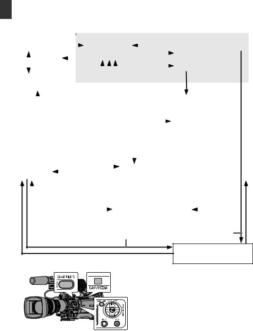
Operation Modes
This camera recorder has four operation modes - Camera mode, Media mode, USB mode and Remote Edit mode.
Introduction
|
Camera Mode |
|
|
|
|
|
|
|
|
|
|
|
|
|
|
|
Media Mode |
|
||||||||||||||||||
|
|
|
|
|
|
|
|
|
|
|
|
|
|
|
|
|
|
|
|
|
|
|
|
|
|
|
|
|
|
|
|
|
|
|
|
|
|
|
|
|
|
|
|
|
|
|
|
Press and hold [CAM/MEDIA] |
[CANCEL]/[MENU/THUMB] Button |
|
|||||||||||||||||||||||
|
Camera Input |
|
|
|
|
|
||||||||||||||||||||||||||||||
|
|
|
|
|
|
|
|
Thumbnail Display |
|
|
|
|
|
|
|
Playback |
|
|
||||||||||||||||||
|
|
|
|
|
|
|
|
|
|
|
|
|
|
|
|
|
|
|
|
|
|
|
||||||||||||||
|
|
|
|
|
|
|
|
|
|
|
|
|
|
|
|
|
|
|
|
Normal Playback |
|
|
|
|
|
|
||||||||||
|
|
|
|
|
|
|
|
|
|
|
|
|
|
|
|
|
|
|
|
|
|
|
|
|
|
|
|
|
|
|
|
|
|
|||
|
|
|
Switch from |
|
|
|
|
|
|
|
|
|
|
|
|
|
|
|
Playback |
|
|
|
|
|
|
|
|
|
||||||||
|
|
|
|
|
|
|
|
|
|
|
|
|
|
|
|
|
|
Button |
|
|
|
|
|
|
|
|
|
|
|
|
||||||
|
|
|
|
|
|
|
|
|
|
|
|
|
|
|
|
|
|
|
|
|
|
|
|
|
|
|
|
|||||||||
|
|
|
|
Menu |
|
[CAM/MEDIA] |
|
|
|
|
|
|
|
|
|
|
|
Trimming Playback |
|
|
|
|
|
|
||||||||||||
|
|
|
|
|
|
|
|
|
Execute [Trim This |
|
|
|
|
|
|
|
|
|
||||||||||||||||||
|
|
|
|
|
|
|
|
|
Button |
|
|
|
|
|
|
|
|
|
|
|
|
|
|
|
|
|||||||||||
|
|
|
|
|
|
|
|
|
|
|
|
|
|
|
|
|
|
|
|
|
|
|
||||||||||||||
|
|
SDI Input |
|
|
|
|
|
|
|
|
|
|
|
|
|
|
|
|
Clip] |
|
|
|
|
|
|
|
|
|
|
|
|
|||||
|
|
|
|
|
|
|
|
|
|
|
|
|
|
|
|
|
|
|
|
|
|
|
|
|
|
|
|
|
|
|
|
|||||
|
|
|
|
|
|
|
|
|
|
|
|
|
|
|
|
|
|
|
Exit Trimming Operation |
|
|
|
[LOAD FILE/3] |
|
|
|
||||||||||
|
|
|
|
|
|
|
|
|
|
|
|
|
|
|
|
|
|
|
(Successful/Failed/Stopped) |
|
Button |
|
|
|
||||||||||||
|
|
|
|
|
|
|
|
|
|
|
|
|
|
|
|
|
|
|
|
|
||||||||||||||||
|
|
|
|
|
|
|
|
|
|
|
|
|
|
|
|
|
|
|
|
|
|
|
|
|
|
|
|
Trimming in Progress |
|
|
|
|
||||
|
|
|
|
|
|
|
|
|
|
|
|
|
|
|
|
|
|
|
|
|
|
|
|
|
|
|
|
|
||||||||
|
|
|
|
|
|
|
|
|
|
|
|
|
|
|
|
|
|
|
|
|
|
|
|
|
|
|
||||||||||
|
|
|
|
|
|
|
|
|
|
|
|
|
|
|
|
|
Exit/Cancel File Delete Operation (Successful/Failed/Stopped) |
|
|
|
|
|||||||||||||||
|
|
|
|
|
|
|
|
|
|
|
|
|
|
|
|
|
|
|
|
|
|
|
|
|
|
|
|
|
|
|
|
|||||
|
|
|
|
Exit FTP |
|
|
|
|
|
|
|
|
|
|
|
|
|
|
|
|
|
|
|
File Deletion in Progress |
|
|
|
|
||||||||
|
|
|
|
|
|
|
|
|
|
|
Execute [Delete Clips] |
|
|
|
|
|||||||||||||||||||||
|
|
|
|
Operation |
|
|
|
|
|
|
|
|
|
|
|
|
|
|
|
|
|
|
|
|||||||||||||
|
|
|
|
|
|
|
|
|
|
|
(Actions) |
|
|
|
|
|
|
|
|
|
|
|
|
|||||||||||||
|
|
|
|
(Successful) |
|
|
|
|
|
|
|
|
|
|
|
|
|
|
|
|
|
|
|
|||||||||||||
|
|
|
|
|
|
|
|
|
|
|
Exit/Cancel FTP Operation (Successful/Failed/Stopped) |
|
|
|
|
|||||||||||||||||||||
|
|
|
|
|
|
|
|
|
|
|
|
|
|
|
|
|
|
|
||||||||||||||||||
|
|
|
|
|
|
|
|
|
|
|
|
|
|
|
|
|
|
|
|
|
|
|
Execute [FTP Upload] |
|
|
|
|
|||||||||
|
|
|
|
|
|
|
|
|
|
|
Press and hold |
|
|
|
|
|
|
|
|
|
|
|||||||||||||||
|
|
|
|
|
|
|
|
|
|
|
|
|
|
|
|
|
|
|
|
|
|
|
|
|
|
|
|
|
|
|
||||||
|
|
|
|
|
|
|
|
|
|
|
[CAM/MEDIA] |
|
|
|
|
|
|
|
|
|
|
|
|
|
|
|
|
|
|
|
|
|||||
|
|
|
|
|
|
|
|
|
|
|
|
|
|
|
|
|
|
|
|
|
|
|
|
|
|
|
|
|
|
|
||||||
|
FTP in Progress |
|
|
|
|
|
|
|
|
|
|
|
|
|
|
FTPFTP in Progress |
|
|
|
|
|
|
|
|
|
|
|
|
|
|||||||
|
|
|
|
|
|
|
|
|
|
|
|
|
|
|
|
|
|
|
|
|
|
|
|
|
|
|||||||||||
|
|
|
|
|
|
|
|
|
|
|
[CAM/MEDIA] Button |
|
|
|
|
|
|
|
|
|
|
|
|
|
|
|||||||||||
|
|
|
Connection disabled on PC |
|
|
|
|
USB Connection (When the confirmation to change to |
|
|
|
* |
||||||||||||||||||||||||
|
|
|
|
|
|
|
|
|
|
|||||||||||||||||||||||||||
|
|
|
|
|
|
|
|
|
|
|
|
|
|
|
|
|
|
|
|
|
|
|||||||||||||||
|
|
|
|
|
|
|
|
|
|
|
|
|
|
|
|
|
|
|
|
|
|
|
USB mode appears and [Change] is selected) |
|
|
|
||||||||||
|
|
|
|
|
|
|
|
|
|
|
|
|
|
|
|
|
|
|
|
|
|
|
|
|
|
|
|
|
|
|
|
|
|
|
|
|
|
|
|
Connection to PC with USB Cable |
|
|
|
|
|
|
|
USB Mode |
|
|
|
|
|
|
|
|
|
|
|
|
|||||||||||||
|
|
|
|
|
|
|
|
|
|
|
|
|
|
|
|
|
|
|
|
(USB Mass Storage Class) |
|
|
|
|
|
|
|
|
||||||||
|
|
|
|
|
|
|
|
|
|
|
|
|
|
|
|
|
|
|
|
|
|
|
|
|
|
|
|
|
|
|
|
|
|
|
|
|
Upon access via a web browser and selecting [Change] on the [Change to Remote Edit Mode?] screen on the camera or the web browser
Remote edit mode
* Selecting a mode other than the Metadata Edit mode via the web browser, or selecting [Exit] on the [Remote Edit Mode] screen
18 Operation Modes
Operation Mode |
|
|
Description |
|
|
Camera Mode |
|
0 This is the camera shooting mode. The camera recorder starts up in Camera mode when |
|
|
|
|
|
the power is turned on. |
|
|
|
|
|
0 Camera images are output on the viewfinder and LCD monitor. When a recordable SD card |
|
|
|
|
|
|
|
||
|
|
is inserted, the camera recorder enters the recording standby mode. “STBY” appears on |
|
|
|
|
|
the operation mode display area of the LCD monitor and viewfinder. |
|
|
|
|
|
0 Press the [REC] trigger button to start recording. |
|
|
|
|
|
0 When [System] B [Record Set] B [Record Format] B [System] is set to “HD(SDI In)” or |
|
Introduction |
|
|
|
“SD(SDI In)”, and the device is connected to the [SDI IN] terminal, the SDI input video is |
|
||
|
|
displayed on the LCD monitor or viewfinder. AB |
|
|
|
|
|
(A P168 [Inputting SDI Signals from an External Device AB] ) |
|
|
|
|
Memo : |
|
|
|
|
|
|
|
|
||
|
|
0 Playback of SD card is not possible in Camera mode. However, you can check the most |
|
|
|
|
|
recently recorded video clip. |
|
|
|
|
|
(A P83 [Viewing Recorded Videos Immediately (Clip Review)] ) |
|
|
|
|
|
|
|
|
|
Media Mode |
|
0 This mode allows you to play back or delete clips recorded on the SD card. |
|
|
|
|
|
0 When a playable SD card is inserted, the thumbnail or playback screen is displayed on the |
|
|
|
|
|
viewfinder and LCD monitor. |
|
|
|
|
|
0 Press and hold the [CAM/MEDIA] selection button to enter the Media mode when you are |
|
|
|
|
|
not shooting in the Camera mode. Once the camera recorder is in Media mode, thumbnails |
|
|
|
|
|
of the selected media slot are displayed. |
|
|
|
USB Mode |
|
0 This mode allows you to connect to a PC and transfer the files on an SD card to the PC. |
|
|
|
|
|
(Writing is not allowed) |
|
|
|
|
|
0 When the camera recorder is connected to a USB cable, the message “Change to USB |
|
|
|
|
|
Mode?” appears. |
|
|
|
|
|
Select [Change] and press the Set button to switch to USB mode. |
|
|
|
|
|
(A P160 [Managing/Editing Clips on a PC] ) |
|
|
|
|
|
0 In USB mode, the camera recorder is recognized by the connected PC as a peripheral drive. |
|
|
|
|
|
(USB mass storage class only) |
|
|
|
|
|
Disable the connection on the PC and remove the USB cable from the camera recorder to |
|
|
|
|
|
switch to Camera mode. |
|
|
|
|
|
(A P160 [Managing/Editing Clips on a PC] ) |
|
|
|
|
Memo : |
|
|
|
|
|
|
|
|
||
|
|
0 When a USB cable is connected during recording, the message appears after recording |
|
|
|
|
|
stops. |
|
|
|
|
|
0 If playback is in progress, the message appears once the files are closed automatically, |
|
|
|
|
|
such as when playback stops. |
|
|
|
|
|
0 Files on the PC cannot be written to the SD card. |
|
|
|
|
|
|
|
|
|
Remote Edit Mode |
|
0 This mode enables the list display and editing of the recorded clip data through access to |
|
|
|
|
|
the clip list display page via a web browser on a smartphone, tablet terminal, or PC. |
|
|
|
|
|
0 When you access via a web browser on a smartphone, tablet terminal, or PC, “It is necessary |
|
|
|
|
|
to change the camera mode to "Remote Edit Mode". Change the mode.” appears on the |
|
|
|
|
|
web browser. Also, “Change to Remote Edit Mode?” is displayed on the display screen of |
|
|
|
|
|
the camera unit. |
|
|
|
|
|
Selecting [Change] on the camera recorder and pressing the Set button switches to the |
|
|
|
|
|
Remote Edit mode, and enables display of the clip list and editing of the clip metadata. |
|
|
|
|
|
(A P184 [ Clip Metadata ] ) |
|
|
|
|
|
(A P187 [Uploading a Recording Clip via a Web Browser] ) |
|
|
|
|
Memo : |
|
|
|
|
|
|
|
|
||
|
|
0 If you access via a web browser on devices such as a smartphone, tablet terminal, or PC |
|
|
|
|
|
while recording is in progress, the message appears after recording stops. |
|
|
|
|
|
0 If playback is in progress, the message appears once the files are closed automatically, |
|
|
|
|
|
such as when playback stops. |
|
|
|
|
|
|
|
|
|
Operation Modes 19

Names of Parts
Introduction
O NM L K
A
B


 J
J
F G H I |
C DE
A Front Tally Lamp
(A P42 [Tally Lamp] )
(A P206 [Blinking of the Tally Lamp] )
B Viewfinder Cable Clamp
(A P28 [Attaching the Viewfinder (Supplied)] )
C Cross-Shaped Button (JKHI)/Set Button (R) |
|||
The function changes according to the |
|||
operation status of the camera recorder. |
|||
0 During menu operation (all modes) |
|||
(A P103 [Basic Operations in Menu Screen] ) |
|||
Center Set button (R) |
: |
Confirms menu |
|
|
|
items and setting |
|
Cross-Shaped Button |
: |
values |
|
Selects menu |
|||
(JKHI) |
|
items and setting |
|
0 During Camera mode |
|
values |
|
: |
You can also use |
||
[5/J][K/6][7/H/ |
|||
ZEBRA][8/I/SPOT |
|
it as a user button |
|
METER] |
|
by assigning a |
|
specific feature in the menu setting to this button.
(A P42 [Assignment of Functions to User Buttons] )
(A P79 [Setting Zebra Pattern] )
(A P80 [Setting Spot Meter] )
D [AWB/9] Auto White Balance/User 9 Button
0Auto White Balance starts up when the [WHT.BAL B/A/PRESET] switch J on the operation panel located at the right side of this unit is set to “A” or “B”.
0 It is used to switch the color temperature of the preset white balance when the [WHT.BAL B/A/PRESET] switch J on the operation panel located at the right side of this unit is set to “PRESET”.
0 You can also use it as a user button by assigning a specific feature in the menu setting to this button.
(A P63 [Adjusting the White Balance] ) (A P42 [Assignment of Functions to User Buttons] )
E Lens Lock Lever
(A P28 [Attaching the Lens (Supplied)] )
F [AUTO FOCUS/11] Autofocus/User 11 Switch For switching the Autofocus function ON or OFF. F
You can also use it as a user button by assigning a specific feature in the menu setting to this button.
This switch operates only with the supplied lens.
G [STATUS] Status Screen Display Button Press the [STATUS] button to display the status screen on the viewfinder and LCD monitor during normal screen display (when the menu screen is not displayed).
H [CAM/MEDIA] Camera/Media Mode Selection
Button
(A P18 [Operation Modes] )
I [FULL AUTO ON/OFF] Full Auto Switch (A P57 [Adjusting the Brightness Automatically] )
(A P65 [Automatic White Balance Mode (FAW: Fulltime Auto White balance)] )
20 Names of Parts
e d cb a
a |
REC |
T
W
HOLD |
|
VAR |
OFF |
FIX |
|
|
|
|
|
Z |
|
P |
Y |
|
X |
||
|
Q
R


W
S T U V
J [MONITOR SELECT] Audio Monitor Selection
Switch
(A P72 [Audio Output during Recording] )
K Monitor Speaker (Cheek Pad)
(A P97 [Audio Output during Playback] )
LShoe
For mounting separately sold lights and accessories.
M Microphone Holder Lock Knob (A P28 [Attaching the Microphone (Supplied)] )
N Microphone Holder
(A P28 [Attaching the Microphone (Supplied)] )
OMicrophone
(A P69 [Audio Recording] )
P Back Tally Lamp
(A P42 [Tally Lamp] )
Q [PHONES] Earphone Connection Terminal
(φ3.5)
(A P72 [Audio Output during Recording] )
R [HOST] USB Host Terminal
For connecting an USB adapter according to the intended purpose when you are connecting the unit to a network.
(A P175 [Camera Setup for Network Connection] )
S [LENS] Lens Connection Terminal (12-pin
Connector)
(A P28 [Attaching the Lens (Supplied)] )
T [INPUT1/INPUT2] Audio Input Terminal 1, 2
(XLR 3-pin x 2)
(A P69 [Audio Recording] )
U Lens Cable Clamp
(A P28 [Attaching the Lens (Supplied)] )
V [AUDIO INPUT] Audio Input Signal Selection
Switch 1/2
(A P69 [Audio Recording] )
W [AUDIO SELECT CH-1~CH-4] Audio Input Signal Selection Switch 1 to 4
(A P69 [Audio Recording] )
X Hood Release Button
(A P29 [Attaching/Detaching the Hood A C] )
Y Viewfinder Connection Terminal (20-pin) (A P28 [Attaching the Viewfinder (Supplied)] )
Z Accessory Cable Clamp
a Accessory Mounting Screw Hole (x2)
b [REC/HOLD] Record Trigger Button/Lock
Switch
Starts/stops recording.
Set the switch to [HOLD] to lock the [REC/ HOLD] Trigger button. However, note that the other record trigger buttons are not locked.
c Zoom lever at the Handle F
(A P52 [Using the Zoom Lever at the Handle F] )
d [FIX/VAR/OFF] Zoom Speed Switch F (A P52 [Zoom Operation] )
For switching the zoom speed of the zoom lever c at the handle.
e Handle
Introduction
Names of Parts 21
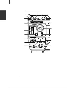
|
Side Control Panel |
|
|
|
A |
|
|
|
B |
|
|
Introduction |
C |
Q |
|
ED |
P |
||
F |
O |
||
|
|||
|
G |
||
|
|
||
|
H |
N |
|
|
I |
M |
|
|
J |
||
|
|
||
|
K |
L |
A [VF BRIGHT] Viewfinder Brightness
Adjustment Knob
(A P40 [Adjusting the Viewfinder] )
B [VF PEAKING] Outline Adjustment Knob
(A P40 [Adjusting the Viewfinder] )
Memo :
0 This knob is disabled when Focus Assist is in operation.
(A P55 [Focus Assist Function] )
C [F.ASSIST/4] Focus Assist/User 4 Button
For switching the focus assist function ON or OFF.
(A P55 [Focus Assist Function] )
You can also use it as a user button by assigning a specific feature in the menu setting to this button.
(A P42 [Assignment of Functions to User Buttons] )
D [OIS/1] Optical Image Stabilizer/User 1 Button
For switching the image stabilizer feature mode ON or OFF. F
You can also use it as a user button by assigning a specific feature in the menu setting to this button.
(A P42 [Assignment of Functions to User Buttons] )
E [MARKER/2] Marker/User 2 Button
This button toggles ON/OFF the marker, safety zone, and center mark displays.
You can also use it as a user button by assigning a specific feature in the menu setting to this button.
(A P154 [Marker and Safety Zone Displays] ) (A P42 [Assignment of Functions to User Buttons] )
F [MENU/THUMB] Menu/Thumbnail Button
0Displays the menu screen during Camera mode.
0Switches between [Main Menu] and [Favorites Menu] when the [MENU/ THUMB] button is pressed and held down
while the menu screen is displayed.
(A P103 [Basic Operations in Menu Screen] )
0Displays the menu screen when the button is pressed during thumbnail display in the Media mode.
0Stops playback and displays the thumbnail screen when the button is pressed during playback screen display in the Media mode.
G [ND FILTER] ND Filter Switch (A P62 [Setting the ND Filter] )
H [DISPLAY] Display Button
0 Press the [DISPLAY] button to switch to the
display screen during normal screen display (when the menu screen is not displayed).
(A P36 [Display Screen] )
0 Switches between [Main Menu] and [Favorites Menu] when the [DISPLAY]
button is pressed while the menu screen is displayed.
(A P103 [Basic Operations in Menu Screen] )
I [GAIN L/M/H] Gain Level Switch
(A P59 [Setting the Gain] )
J [WHT.BAL B/A/PRESET] White Balance
Switch
(A P63 [Adjusting the White Balance] )
K [POWER ON/OFF] Power ON/OFF Switch and
Indicator Lamp
Turns ON/OFF the power. The indicator lamp lights up in green when the power is on. When the power is OFF, “POFF” appears on the
LCD monitor and viewfinder.
Wait for 5 seconds or more to turn on the power again.
L [REC/10] Record Trigger/User 10 Button
Starts/stops recording.
You can also use it as a user button by assigning a specific feature in the menu setting to this button.
(A P42 [Assignment of Functions to User Buttons] )
M [AUDIO LEVEL CH-1/CH-2]/[AUTO]CH-1/
CH-2 Recording Level Adjustment Knob/Auto
Indicator Lamp
(A P69 [Audio Recording] )
N [CANCEL] Cancel Button
Cancels various settings and stops playback.
22 Names of Parts
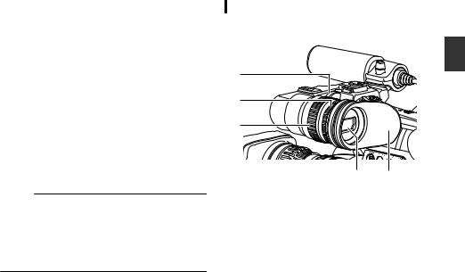
O Cross-Shaped Button (JKHI)/Set Button (R) |
|
The function changes according to the |
|
operation status of the camera recorder. |
|
o During menu operation (all modes) |
|
(A P103 [Basic Operations in Menu Screen] ) |
|
Center Set button (R) |
: Confirms menu items |
Cross-shaped button |
and setting values |
: Selects menu items |
|
(JK) |
and setting values |
o During Camera mode |
|
Shutter operation: |
: Shutter ON/OFF |
Center Set button (R) |
|
Cross-shaped button |
: Switches shutter |
(JK) |
speed when shutter |
is ON Cross-Shaped Button : AE level operation (HI)
Memo :
0 When [Camera Function] B [AE LEVEL SW] is set to “AE LEVEL/VFR”, the cross-shaped
button (HI) is used to set the number of frames during Variable Frame Rec.
(A P93 [Variable Frame Rec] ) (A P109 [ AE LEVEL SW ] )
P [LOAD FILE/3] Load File/User 3 Button
Displays the screen for retrieving a picture file. You can also use it as a user button by assigning a specific feature in the menu setting to this button.
(A P158 [Loading a Setup File] )
(A P42 [Assignment of Functions to User Buttons] )
Q [MONITOR] Audio Monitor Level Adjustment
Knob
For adjusting the volume of the monitor speaker and earphone.
Viewfinder
(A P40 [Adjusting the Viewfinder] )
A
B
C
D E
A Viewfinder Slide Lock Ring
For loosening the ring and adjusting the position of the viewfinder D to the left or right.
B Eyepiece Focus Ring
For adjusting the visibility.
C Viewfinder Eyepiece Lock Ring
For loosening the ring and adjusting the eyepiece position of the viewfinder to the front or back.
D Viewfinder
EEyepiece
Prevents external light from entering the viewfinder screen and cameraman’s vision.
Introduction
Names of Parts 23
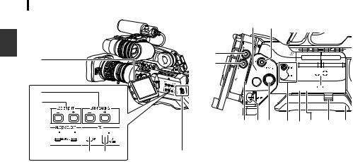
LCD Monitor |
|
Side Terminal Section |
|
B A
Introduction |
A |
|
B |
||
|
||
|
C |
D


E F G
A LCD Monitor
(A P38 [Adjusting the LCD Monitor and Viewfinder] )
B [LCD PEAKING +/-] LCD Outline Adjustment
Button
(A P39 [Adjusting the LCD Monitor] )
C [LCD BRIGHT +/-] LCD Display Brightness
Adjustment Button
(A P39 [Adjusting the LCD Monitor] )
D [AUDIO SELECT CH-1/CH-2 AUTO/MANUAL]
Selection Switch
(A P69 [Audio Recording] )
E [TC DISPLAY] TC/UB Display Switch
(A P72 [Time Code and User’s Bit] ) (A P73 [Setting Time Code Generator] )
F [TC GENE.] Time Code Generator Switch
(A P72 [Time Code and User’s Bit] ) (A P73 [Setting Time Code Generator] )
(A P78 [Synchronizing the Time Code with an External Time Code Generator] )
G LCD Cover Lock Release Knob
C D
E


 P F
P F


 O
O
G H I J K L M N
*GY-HM890U/GY-HM890E/GY-HM890CHU/GY- HM890CHE is used in the illustration here.
A [HD/SD SDI IN] HD/SD SDI Input Terminal
(BNC) AB
(A P168 [Inputting SDI Signals from an External Device AB] )
B [HD/SD SDI OUT] HD/SD SDI Output Terminal
(BNC)
(A P161 [Connecting External Monitor] )
C [GENLOCK] Genlock Terminal (BNC)
(A P169 [Inputting External Synchronizing Signals (Genlock)] )
D [TC IN] Time Code Input Terminal (BNC)
(A P78 [Synchronizing the Time Code with an External Time Code Generator] )
E [TC OUT] Time Code Output Terminal (BNC)
(A P78 [Synchronizing the Time Code with an External Time Code Generator] )
F [STUDIO] Studio Terminal (Mini DIN) AB
Connect to this terminal when you are combining the use of devices such as a transmission unit manufactured by a different company.
(A P172 [Displaying Return Videos from an External Device AB] )
G [VIDEO OUT] Video Output Terminal (BNC)
(A P78 [Synchronizing the Time Code with an External Time Code Generator] )
H [DC INPUT] DC Input Terminal
Input terminal for DC 12 V power supply. Connect it with an AC adapter.
(A P30 [Using AC Power (DC IN Power)] )
I [REMOTE1] Remote 1 Terminal
(A P164 [Connecting a Remote Control Unit] )
24 Names of Parts

J [AUDIO OUTPUT CH-1/3, CH-2/4] Audio |
Rear Terminal |
|
|
||
Output Terminal (RCA) |
|
|
|
|
|
Output terminal for audio signals. |
|
|
|
|
|
0 Input audio signals are output during |
|
A |
|
|
|
Camera mode. |
|
|
|
A |
|
0 Playback audio signals are output during |
|
|
|
||
Media mode. |
|
|
|
|
Introduction |
0 In the SDI signal input mode, audio signals |
|
|
|
||
superimposed with the SDI input are output. |
|
|
|
||
|
|
|
|
||
Memo : |
|
|
|
|
|
0 Alarm audio is not output. |
|
B |
|
|
|
K [AUX] AUX Input terminal (φ3.5 Stereo Mini |
|
|
|
|
|
Jack) |
|
|
|
|
|
(A P69 [Audio Recording] ) |
|
|
|
C |
|
L [REMOTE2] Remote 2 Terminal |
|
|
|
|
|
(A P164 [Connecting Wired Remote Control] ) |
A Shoulder Belt Mount (x2) |
|
|||
M Shoulder Pad Slide Button |
|
For mounting a shoulder belt (sold separately). |
|||
For adjusting the shoulder pad position. Press |
Caution : |
|
|
||
this button to adjust the shoulder pad Nposition |
0 Be sure to use a shoulder belt with the strength |
||||
to the front or back. |
|
|
to withstand the weight of this camera recorder. |
||
N Shoulder Pad |
|
0 If the shoulder belt is not properly attached, the |
|||
O [DEVICE] USB Mini Terminal |
|
camera recorder may fall and cause injuries. |
|||
(A P160 [Managing/Editing Clips on a PC] ) |
0 Check the instruction manual provided with the |
||||
|
shoulder belt before using. |
|
|||
P [HDMI] HDMI Output Terminal |
|
|
|||
|
Accessory Connection Terminal |
|
|||
(A P161 [Connecting External Monitor] ) |
B |
AB |
|||
|
|
|
Terminal for connecting a KA-M790G |
||
SD Slot |
|
|
(Multicore Remote Adapter: sold separately) or |
||
|
|
other units. |
|
|
|
(A P43 [SD Card] ) |
|
Memo : |
|
|
|
|
0 When using this terminal, make sure that the |
||||
E |
D |
|
Battery Adapter |
C is removed. |
|
|
|
C Battery Loading Folder |
|
||
|
|
|
The shape varies across the U and E models. |
||
|
|
|
(A P31 [Using a Battery Pack] ) |
|
|
|
|
* The E model is used in the illustration here. |
|||
C
A
B


A Card Slot A Status Indicator
B [SLOT SELECT] Card Slot Selection Button
For switching the active card slot during shooting and playback.
C SD Card Cover
D Card Slot B Status Indicator
E [OPEN] SD Card Cover Open/Close Knob
Names of Parts 25
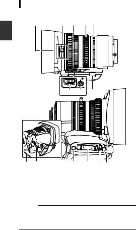
Lens Section AC
A B C D E
Introduction
H G F
REC
I J |
K L MN |
|
A Filter Built-In Screw |
||
0 |
Transparent or UV filter for lens protection, |
|
|
or filters for various effects can be installed. |
|
0 |
Installable filter types: φ72mmP0.75 |
|
Memo :
0 Remove the lens hood when installing the filter.
(A P29 [Attaching/Detaching the Hood A
C] )
B Lens Cover Open/Close Switch
(A P29 [Opening/Closing the Lens Cover
AC] )
C Focus Ring
(A P53 [Focus Operation F] )
D Zoom Ring
(A P52 [Zoom Operation] )
To operate zoom with this ring, set the [ZOOM SERVO/MANUAL] switch H to “MANUAL”.
E Iris Ring
(A P58 [Adjusting the Iris] )
To operate the auto iris, set the [IRIS A/M] mode switch M to “A”.
F Zoom Servo Connector
This is a connector for connecting a zoom servo unit (sold separately). When using a separately sold zoom servo unit, set the [ZOOM SERVO/
MANUAL] switch H to “SERVO”.
G [F.f] Back Focus Button and Indicator Lamp (A P41 [Adjusting Back Focus] )
H [ZOOM SERVO/MANUAL] Zoom Operation
Servo/Manual Switch
Set to “SERVO” in the following cases.
0When using the grip zoom lever L on the lens, or the handle zoom lever con this unit
0When using a zoom servo unit (sold separately)
0When operating remotely from a remote control unit connected to the [REMOTE1]/ [REMOTE2] terminal or from a web browser
(A P52 [Zoom Operation] )
I Lens Cable
For connecting to the camera’s [LENS] connection terminal.
J [REC] Record Trigger Button Starts/stops recording.
K [RET] Return Video Button
Functions as a push autofocus button. F
(A P54 [Setting to Auto Focus Temporarily (Push Auto Focus)] )
You can also use it as a user button by assigning a specific feature in the menu setting to this button.
(A P42 [Assignment of Functions to User Buttons] )
L Zoom Lever at the Grip
To operate zoom servo with the zoom lever at the grip, set the [ZOOM SERVO/MANUAL]
switch 8 to “SERVO”.
(A P52 [Using the Zoom Lever at the Grip] )
M [IRIS A/M] Iris Mode Switch
Switches the mode of the iris ring 5. Select “A” to set to auto iris, and “M” to set to manual iris.
N [IRIS] Iris Momentary Button
When the [IRIS A/M] mode switch M is set to “M”, Auto Iris mode is enabled while the button is pressed down.
26 Names of Parts

Basic System Diagram
Caution :
0 VF-HP840U does not function even when it is connected to this camera recorder.
Focus Manual Unit HZ-FM13 FUJINON HZ-FM15 CANON
PL Mount
Film Lens
|
Wireless Microphone |
|
Camera Recorder |
|
Shoulder Belt |
Receiver |
[SDI OUT] |
|
|
|
|
|
|
|
|
|
|
SDI Cable BNC |
|
Earphone |
|
Composite Cable |
|
|
|
BNC |
Monitor |
||
|
|
|
Audio Cable |
|
|
|
|
RCA pin |
|
|
[AUX] |
[SDI IN] |
HDMI Cable |
|
Microphone |
|
[HOST] |
|
|
|
|
|
Network Adapter |
Monitor |
|
|
|
U model |
|
16 mm PL Mount Film Lens adapter HZ-CA13U
Zoom Servo Unit
HZ-ZS13B
1/2 Zoom Lens
1/3 AF Zoom Lens
Standard Package
|
|
|
External Recording |
|
Anton/Bauer Anton/Bauer |
Device |
|
|
Battery |
Battery |
|
Battery Mount |
(Dionic90) |
Charger |
|
|
|
|
|
U model : Gold Mount |
|
E model |
|||
E model : V Mount |
|
|
|
IDX |
|
|
|
|
|
|
|
|
|
|
|
|
Battery Charger |
|
|
|
|
|
|
|
|
|
IDX Battery |
|
|
Mount |
|
(Endura-HL9) |
|
|
|
|
|
|
|
Converter |
|
|
AC |
(1/2 |
1/3) : ACM-12 |
Tripod Base |
XLR 4-pin |
|
|
|
KA-551U |
|
AC Adapter |
Carrying |
|
|
|
Remote Control Unit |
Case |
|
|
|
RM-LP25U/RM-LP55U/ |
|
|
|
|
|
|
|
|
|
RM-LP20G |
Mount Converter |
Tripod |
|
USB Cable |
|
2/3 Zoom Lens (2/3 1/3) : ACM-17 |
|
|||
|
|
SD Card |
SD Card Reader |
Non-linear Editing |
|
|
|
|
System |
|
|
|
Remote Fiber Adapter KA-F790 |
|
Studio Viewfinder |
|
|
Headset |
|
VF-HP790G |
|
|
|
|
|
|
|
|
Remote Control Unit |
|
|
|
|
RM-LP25U/RM-LP55U/ |
|
|
Multicore Remote |
Monitor |
RM-LP20G |
|
|
|
||
Studio Adapter |
|
Adapter |
|
|
KA-790G |
|
KA-M790G |
Camera Remote Control Unit |
|
|
|
|
||
RM-HP790DU/RM-HP790DE
Introduction
.
* Models with an E suffix are for the European market and the UL Listing mark is not applicable.
Basic System Diagram 27
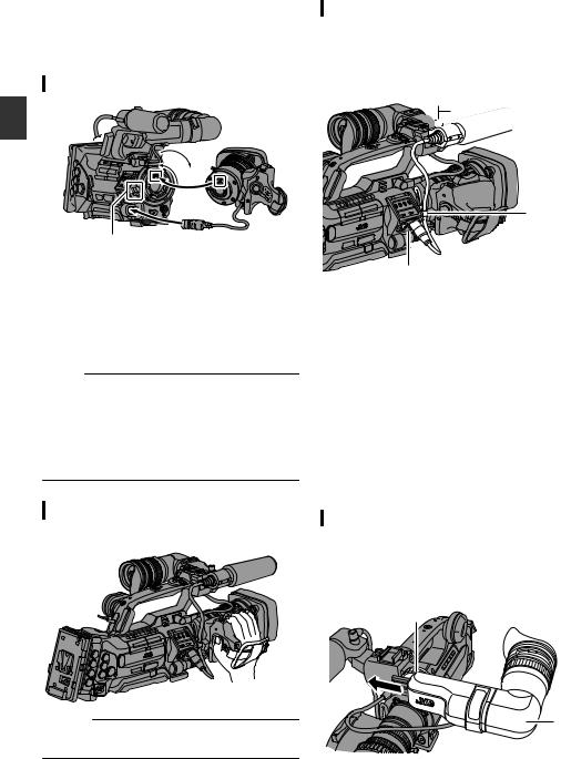
Settings and Adjustments
Before Use
Attaching the Lens (Supplied)
Preparations |
1 3 |
|
2 |
||
|
5 4
1 Loosen the mount ring.
2Attach the zoom lens such that the pin matches the hole of the mounting area.
3 Tighten the mount ring.
4 Connect the cable connector.
5 Attach the lens cable to the clamp.
Memo :
0To attach or detach the zoom lens, set the [POWER ON/OFF] switch on this unit to “OFF”.
0Tighten the mount ring completely. If it is not fully tightened, the lens may drop or the back focus may be out of alignment.
0Lens is supplied for GY-HM890U, GY-HM890E, GY-HM850U, and GY-HM850E.
Adjusting the Grip Belt AC
Adjust the grip belt.
Caution :
0If the grip is loose, the camera recorder may fall off resulting in injuries or malfunction.
Attaching the Microphone (Supplied)
You can attach the supplied microphone to the microphone holder.
The supplied microphone uses a phantom power supply.
1, 3


 2
2
5
4
1Turn the knob on the microphone holder anticlockwise to loosen and open the microphone holder.
2Place the microphone in the microphone holder.
3Turn the knob on the microphone holder clockwise to secure the microphone.
4Connect the microphone cable to the [INPUT1] or [INPUT2] terminal.
5 Pin the microphone cable to the clamp.
6Perform the settings for the phantom mic correctly.
(A P69 [Audio Recording] )
Attaching the Viewfinder (Supplied)
1Slide the viewfinder in the direction of the arrow to attach it.
2Turn the slide lock ring to secure the position of the viewfinder.
2
1
28 Settings and Adjustments Before Use

3Attach the viewfinder cable to the viewfinder terminal.
4 Pin the viewfinder cable to the clamp.
4


 3
3
Memo :
0To attach or detach the viewfinder, set the [POWER ON/OFF] switch on this unit to “OFF”.
Opening/Closing the Lens Cover A
C
Use the lens cover open/close switch to open or close the lens cover.
Before shooting, open the lens cover.
When this camera recorder is not in use, close the lens cover to protect the lens.
Caution :
0Do not press against the lens cover with force. Doing so may damage the lens or the cover.
Attaching/Detaching the Hood AC
Attaching the Hood
Align the markings on the camera recorder and hood; turn the hood in the direction of the arrow until it is locked.
Preparations
Detaching the Hood
0Remove the hood when attaching a filter, teleconverter or wide converter to the front of the lens.
0While pressing the hood release button, turn the hood in the anti-clockwise direction to remove it.
Settings and Adjustments Before Use 29
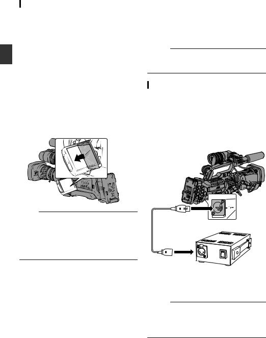
Preparations
Attaching the Anti-reflective Film
Attach the supplied anti-reflective film onto the LCD monitor if necessary, such as when you are recording in the day or outdoors.
Doing so helps to cut down reflection of outside light, thus improving the visibility.
1Wipe off any dirt, dust or stains on the surface of the LCD monitor.
2Peel off the backing of the anti-reflective film halfway.
Pay attention to prevent fingerprints from being left on the adhesive face.
3 Attaching the Anti-reflective Film
0 Attach the anti-reflective film by aligning it with the corners of the LCD monitor, while ensuring that there are no air bubbles.
0 Squeeze the air bubbles out.
0 In case if the anti-reflective film is not correctly attached, you can wash and reuse it.
Memo :
0Do not press the LCD monitor surface with excessive force when attaching the film.
0For additional orders of the anti-reflective film, please consult the authorized dealer from which this camera recorder was purchased, or our service center.
Anti-reflective film model: LS43131
Power Supply
To use this camera recorder, you can attach a battery pack or connect an AC adapter to it.
(A P31 [Using a Battery Pack] )
(A P30 [Using AC Power (DC IN Power)] ) Caution :
0Set the [POWER ON/OFF] switch to “OFF” before changing the power supply that operates this camera recorder.
Using AC Power (DC IN Power)
Use the AC adapter (sold separately) to operate the camera recorder with AC power.
1Connect the DC cable of the AC adapter to the [DC INPUT] terminal of the camera recorder.
Check that the power of this unit and that of the AC adapter are both set to “OFF”, followed by connecting according to the diagram.
2Turn on the power of the AC adapter, followed by setting the [POWER ON/OFF] switch of this unit to “ON”.
Power will be supplied to the camera recorder.
Caution :
0Do not insert or remove the DC cable during recording.
0Do not use power supply of high voltage fluctuation, containing noise such as ripple, or with insufficient capacity.
30 Settings and Adjustments Before Use
 Loading...