

Page 1

Service and Maintenance Manual
Models
800S
860SJ
P/N - 3121139
November 16, 2012
Page 2

Page 3

INTRODUCTION
SECTION A. INTRODUCTION - MAINTENANCE SAFETY PRECAUTIONS
A GENERAL
This section contains the general safety precautions
which must be observed during maintenance of the aerial
platform. It is of utmost importance that maintenance personnel pay strict attention to these warnings and precautions to avoid possible injury to themselves or others, or
damage to the equipment. A maintenance program must
be followed to ensure that the machine is safe to operate.
MODIFICATION OR ALTERATION OF AN AERIAL WORK PLATFORM
SHALL BE MADE ONLY WITH WRITTEN PERMISSION FROM THE
MANUFACTURER.
The specific precautions to be observed during maintenance are inserted at the appropriate point in the manual.
These precautions are, for the most part, those that apply
when servicing hydraulic and larger machine component
parts.
Your safety, and that of others, is the first consideration
when engaging in the maintenance of equipment. Always
be conscious of weight. Never attempt to move heavy
parts without the aid of a mechanical device. Do not allow
heavy objects to rest in an unstable position. When raising
a portion of the equipment, ensure that adequate support
is provided.
SINCE THE MACHINE MANUFACTURER HAS NO DIRECT CONTROL OVER THE FIELD INSPECTION AND MAINTENANCE, SAFETY
IN THIS AREA IS THE RESPONSIBILITY OF THE OWNER/OPERATOR.
B HYDRAULIC SYSTEM SAFETY
It should be noted that the machines hydraulic systems
operate at extremely high potentially dangerous pressures. Every effort should be made to relieve any system
pressure prior to disconnecting or removing any portion of
the system.
C MAINTENANCE
FAILURE TO COMPLY WITH SAFETY PRECAUTIONS LISTED IN
THIS SECTION COULD RESULT IN MACHINE DAMAGE, PERSONNEL INJURY OR DEATH AND IS A SAFETY VIOLATION.
• ENSURE REPLACEMENT PARTS OR COMPONENTS
ARE IDENTICAL OR EQUIVALENT TO ORIGINAL PARTS
OR COMPONENTS.
• NO SMOKING IS MANDATORY. NEVER REFUEL DURING ELECTRICAL STORMS. ENSURE THAT FUEL
CAP IS CLOSED AND SECURE AT ALL OTHER
TIMES.
• REMOVE ALL RINGS, WATCHES AND JEWELRY
WHEN PERFORMING ANY MAINTENANCE.
• DO NOT WEAR LONG HAIR UNRESTRAINED, OR
LOOSE-FITTING CLOTHING AND NECKTIES WHICH
ARE APT TO BECOME CAUGHT ON OR ENTANGLED
IN EQUIPMENT.
• OBSERVE AND OBEY ALL WARNINGS AND CAUTIONS ON MACHINE AND IN SERVICEMANUAL.
• KEEP OIL, GREASE, WATER, ETC. WIPED FROM
STANDING SURFACES AND HAND HOLDS.
• USE CAUTION WHEN CHECKING A HOT, PRESSURIZED COOLANT SYSTEM.
• NEVER WORK UNDER AN ELEVATED BOOM UNTIL
BOOM HAS BEEN SAFELY RESTRAINED FROM ANY
MOVEMENT BY BLOCKING OR OVERHEAD SLING,
OR BOOM SAFETY PROP HAS BEEN ENGAGED.
• BEFORE MAKING ADJUSTMENTS, LUBRICATING OR
PERFORMING ANY OTHER MAINTENANCE, SHUT
OFF ALL POWER CONTROLS.
• BATTERY SHOULD ALWAYS BE DISCONNECTEDDURING REPLACEMENT OF ELECTRICAL COMPONENTS.
• KEEP ALL SUPPORT EQUIPMENT AND ATTACHMENTS STOWED IN THEIR PROPER PLACE.
• USE ONLY APPROVED, NONFLAMMABLE CLEANING
SOLVENTS.
Relieve system pressure by cycling the applicable control
several times with the engine stopped and ignition on, to
direct any line pressure back into the reservoir. Pressure
feed lines to system components can then be disconnected with minimal fluid loss.
3121139 – JLG Lift – A-1
Page 4

INTRODUCTION
REVISON LOG
Original Issue - October 31, 2001
Revised - January 16, 2002
Revised - February 4, 2002
Revised - May 10, 2002
Revised - July 2, 2003
Revised - July 14, 2005
Revised - November 17, 2005
Revised - March 6, 2006
Revised - November 21, 2007
Revised - July 25, 2008
Revised - November 16, 2012
A-2 – JLG Lift – 3121139
Page 5

TABLE OF CONTENTS
SECTION NO. TITLE PAGE NO.
SECTION A - INTRODUCTION - MAINTENANCE SAFETY PRECAUTIONS
A General . . . . . . . . . . . . . . . . . . . . . . . . . . . . . . . . . . . . . . . . . . . . . . . . . . . . . . . . . . . . . . . . . . . . . .A-1
B Hydraulic System Safety . . . . . . . . . . . . . . . . . . . . . . . . . . . . . . . . . . . . . . . . . . . . . . . . . . . . . . . . . A-1
C Maintenance . . . . . . . . . . . . . . . . . . . . . . . . . . . . . . . . . . . . . . . . . . . . . . . . . . . . . . . . . . . . . . . . . . A-1
SECTION 1 - SPECIFICATIONS
1.1 Operating specifications . . . . . . . . . . . . . . . . . . . . . . . . . . . . . . . . . . . . . . . . . . . . . . . . . . . . . . . . .1-1
1.2 Specifications and Performance Data. . . . . . . . . . . . . . . . . . . . . . . . . . . . . . . . . . . . . . . . . . . . . . .1-1
1.3 Capacities . . . . . . . . . . . . . . . . . . . . . . . . . . . . . . . . . . . . . . . . . . . . . . . . . . . . . . . . . . . . . . . . . . . .1-2
1.4 Component Data . . . . . . . . . . . . . . . . . . . . . . . . . . . . . . . . . . . . . . . . . . . . . . . . . . . . . . . . . . . . . . .1-2
Engine Data . . . . . . . . . . . . . . . . . . . . . . . . . . . . . . . . . . . . . . . . . . . . . . . . . . . . . . . . . . . . . 1-2
Battery . . . . . . . . . . . . . . . . . . . . . . . . . . . . . . . . . . . . . . . . . . . . . . . . . . . . . . . . . . . . . . . . . . 1-3
1.5 Tires . . . . . . . . . . . . . . . . . . . . . . . . . . . . . . . . . . . . . . . . . . . . . . . . . . . . . . . . . . . . . . . . . . . . . . . . . 1-3
1.6 Function Speeds . . . . . . . . . . . . . . . . . . . . . . . . . . . . . . . . . . . . . . . . . . . . . . . . . . . . . . . . . . . . . . .1-3
Machine Orientation When Doing Speed Tests . . . . . . . . . . . . . . . . . . . . . . . . . . . . . . . . . . 1-3
Test Notes . . . . . . . . . . . . . . . . . . . . . . . . . . . . . . . . . . . . . . . . . . . . . . . . . . . . . . . . . . . . . . . 1-4
1.7 Torque Requirements . . . . . . . . . . . . . . . . . . . . . . . . . . . . . . . . . . . . . . . . . . . . . . . . . . . . . . . . . . . 1-4
1.8 Lubrication. . . . . . . . . . . . . . . . . . . . . . . . . . . . . . . . . . . . . . . . . . . . . . . . . . . . . . . . . . . . . . . . . . . .1-4
Hydraulic Oil . . . . . . . . . . . . . . . . . . . . . . . . . . . . . . . . . . . . . . . . . . . . . . . . . . . . . . . . . . . . . 1-4
1.9 Pressure Settings . . . . . . . . . . . . . . . . . . . . . . . . . . . . . . . . . . . . . . . . . . . . . . . . . . . . . . . . . . . . . .1-5
1.10 Major Component Weights . . . . . . . . . . . . . . . . . . . . . . . . . . . . . . . . . . . . . . . . . . . . . . . . . . . . . . .1-5
1.11 Operator Maintenance . . . . . . . . . . . . . . . . . . . . . . . . . . . . . . . . . . . . . . . . . . . . . . . . . . . . . . . . . .1-6
Draining Oil Build Up From The Propane Regulator. . . . . . . . . . . . . . . . . . . . . . . . . . . . . . . 1-10
Propane Fuel Filter Replacement . . . . . . . . . . . . . . . . . . . . . . . . . . . . . . . . . . . . . . . . . . . . . 1-11
Propane Fuel System Pressure Relief . . . . . . . . . . . . . . . . . . . . . . . . . . . . . . . . . . . . . . . . . . 1-12
1.12 Serial Number Location. . . . . . . . . . . . . . . . . . . . . . . . . . . . . . . . . . . . . . . . . . . . . . . . . . . . . . . . . . 1-12
SECTION 2 - GENERAL
2.1 Machine Preparation, Inspection, and Maintenance . . . . . . . . . . . . . . . . . . . . . . . . . . . . . . . . . . .2-1
General. . . . . . . . . . . . . . . . . . . . . . . . . . . . . . . . . . . . . . . . . . . . . . . . . . . . . . . . . . . . . . . . . . 2-1
Preparation, Inspection, and Maintenance . . . . . . . . . . . . . . . . . . . . . . . . . . . . . . . . . . . . . . 2-1
Pre-Start Inspection . . . . . . . . . . . . . . . . . . . . . . . . . . . . . . . . . . . . . . . . . . . . . . . . . . . . . . . . 2-1
Pre-Delivery Inspection and Frequent Inspection . . . . . . . . . . . . . . . . . . . . . . . . . . . . . . . . . 2-1
Annual Machine Inspection . . . . . . . . . . . . . . . . . . . . . . . . . . . . . . . . . . . . . . . . . . . . . . . . . . 2-1
Preventative Maintenance . . . . . . . . . . . . . . . . . . . . . . . . . . . . . . . . . . . . . . . . . . . . . . . . . . . 2-1
2.2 Service and Guidelines . . . . . . . . . . . . . . . . . . . . . . . . . . . . . . . . . . . . . . . . . . . . . . . . . . . . . . . . . .2-2
General. . . . . . . . . . . . . . . . . . . . . . . . . . . . . . . . . . . . . . . . . . . . . . . . . . . . . . . . . . . . . . . . . . 2-2
Safety and Workmanship . . . . . . . . . . . . . . . . . . . . . . . . . . . . . . . . . . . . . . . . . . . . . . . . . . . 2-2
Cleanliness. . . . . . . . . . . . . . . . . . . . . . . . . . . . . . . . . . . . . . . . . . . . . . . . . . . . . . . . . . . . . . . 2-2
Components Removal and Installation . . . . . . . . . . . . . . . . . . . . . . . . . . . . . . . . . . . . . . . . . 2-2
Component Disassembly and Reassembly . . . . . . . . . . . . . . . . . . . . . . . . . . . . . . . . . . . . . 2-3
Pressure-Fit Parts. . . . . . . . . . . . . . . . . . . . . . . . . . . . . . . . . . . . . . . . . . . . . . . . . . . . . . . . . . 2-3
Bearings . . . . . . . . . . . . . . . . . . . . . . . . . . . . . . . . . . . . . . . . . . . . . . . . . . . . . . . . . . . . . . . . . 2-3
Gaskets . . . . . . . . . . . . . . . . . . . . . . . . . . . . . . . . . . . . . . . . . . . . . . . . . . . . . . . . . . . . . . . . . 2-3
Bolt Usage and Torque Application . . . . . . . . . . . . . . . . . . . . . . . . . . . . . . . . . . . . . . . . . . . 2-3
Hydraulic Lines and Electrical Wiring . . . . . . . . . . . . . . . . . . . . . . . . . . . . . . . . . . . . . . . . . . 2-3
Hydraulic System. . . . . . . . . . . . . . . . . . . . . . . . . . . . . . . . . . . . . . . . . . . . . . . . . . . . . . . . . . 2-3
Lubrication . . . . . . . . . . . . . . . . . . . . . . . . . . . . . . . . . . . . . . . . . . . . . . . . . . . . . . . . . . . . . . . 2-3
Battery . . . . . . . . . . . . . . . . . . . . . . . . . . . . . . . . . . . . . . . . . . . . . . . . . . . . . . . . . . . . . . . . . . 2-3
Lubrication and Servicing . . . . . . . . . . . . . . . . . . . . . . . . . . . . . . . . . . . . . . . . . . . . . . . . . . . 2-3
3121139 – JLG Lift – i
Page 6

TABLE OF CONTENTS
SECTION NO. TITLE PAGE NO.
2.3 Lubrication and Information . . . . . . . . . . . . . . . . . . . . . . . . . . . . . . . . . . . . . . . . . . . . . . . . . . . . . . 2-4
Hydraulic System. . . . . . . . . . . . . . . . . . . . . . . . . . . . . . . . . . . . . . . . . . . . . . . . . . . . . . . . . . 2-4
Hydraulic Oil . . . . . . . . . . . . . . . . . . . . . . . . . . . . . . . . . . . . . . . . . . . . . . . . . . . . . . . . . . . . . 2-4
Changing Hydraulic Oil . . . . . . . . . . . . . . . . . . . . . . . . . . . . . . . . . . . . . . . . . . . . . . . . . . . . . 2-4
Lubrication Specifications . . . . . . . . . . . . . . . . . . . . . . . . . . . . . . . . . . . . . . . . . . . . . . . . . . . 2-4
2.4 Cylinder Drift Test . . . . . . . . . . . . . . . . . . . . . . . . . . . . . . . . . . . . . . . . . . . . . . . . . . . . . . . . . . . . . .2-4
Platform Drift . . . . . . . . . . . . . . . . . . . . . . . . . . . . . . . . . . . . . . . . . . . . . . . . . . . . . . . . . . . . . 2-4
Cylinder Drift . . . . . . . . . . . . . . . . . . . . . . . . . . . . . . . . . . . . . . . . . . . . . . . . . . . . . . . . . . . . . 2-5
2.5 Pins and Composite Bearing Repair Guidelines . . . . . . . . . . . . . . . . . . . . . . . . . . . . . . . . . . . . . .2-5
2.6 Welding on JLG Equipment . . . . . . . . . . . . . . . . . . . . . . . . . . . . . . . . . . . . . . . . . . . . . . . . . . . . . . 2-5
Do the Following When Welding on JLG Equipment . . . . . . . . . . . . . . . . . . . . . . . . . . . . . . 2-5
Do NOT Do the Following When Welding on JLG Equipment . . . . . . . . . . . . . . . . . . . . . . . 2-5
SECTION 3 - CHASSIS & TURNTABLE
3.1 Tires & Wheels. . . . . . . . . . . . . . . . . . . . . . . . . . . . . . . . . . . . . . . . . . . . . . . . . . . . . . . . . . . . . . . . . 3-1
Tire Inflation . . . . . . . . . . . . . . . . . . . . . . . . . . . . . . . . . . . . . . . . . . . . . . . . . . . . . . . . . . . . . . 3-1
Tire Damage . . . . . . . . . . . . . . . . . . . . . . . . . . . . . . . . . . . . . . . . . . . . . . . . . . . . . . . . . . . . . 3-1
Tire Replacement. . . . . . . . . . . . . . . . . . . . . . . . . . . . . . . . . . . . . . . . . . . . . . . . . . . . . . . . . . 3-1
Wheel Replacement. . . . . . . . . . . . . . . . . . . . . . . . . . . . . . . . . . . . . . . . . . . . . . . . . . . . . . . . 3-1
Wheel Installation. . . . . . . . . . . . . . . . . . . . . . . . . . . . . . . . . . . . . . . . . . . . . . . . . . . . . . . . . . 3-2
3.2 Wheel Drive Assembly, 2WD. . . . . . . . . . . . . . . . . . . . . . . . . . . . . . . . . . . . . . . . . . . . . . . . . . . . . . 3-2
Removal and Disassembly . . . . . . . . . . . . . . . . . . . . . . . . . . . . . . . . . . . . . . . . . . . . . . . . . . 3-2
Assembly and Installation . . . . . . . . . . . . . . . . . . . . . . . . . . . . . . . . . . . . . . . . . . . . . . . . . . . 3-3
3.3 Drive Motor - 2WD (Prior to S/N 83331) . . . . . . . . . . . . . . . . . . . . . . . . . . . . . . . . . . . . . . . . . . . . .3-4
Replacing the Drive Shaft Seal . . . . . . . . . . . . . . . . . . . . . . . . . . . . . . . . . . . . . . . . . . . . . . . 3-4
Disassembly. . . . . . . . . . . . . . . . . . . . . . . . . . . . . . . . . . . . . . . . . . . . . . . . . . . . . . . . . . . . . . 3-5
Assembly . . . . . . . . . . . . . . . . . . . . . . . . . . . . . . . . . . . . . . . . . . . . . . . . . . . . . . . . . . . . . . . . 3-9
3.4 Drive Motor (S/N 83331 to Present) . . . . . . . . . . . . . . . . . . . . . . . . . . . . . . . . . . . . . . . . . . . . . . . . 3-11
Description. . . . . . . . . . . . . . . . . . . . . . . . . . . . . . . . . . . . . . . . . . . . . . . . . . . . . . . . . . . . . . . 3-11
Shaft Seal Replacement . . . . . . . . . . . . . . . . . . . . . . . . . . . . . . . . . . . . . . . . . . . . . . . . . . . . 3-11
Loop Flushing Valve . . . . . . . . . . . . . . . . . . . . . . . . . . . . . . . . . . . . . . . . . . . . . . . . . . . . . . . 3-12
Troubleshooting. . . . . . . . . . . . . . . . . . . . . . . . . . . . . . . . . . . . . . . . . . . . . . . . . . . . . . . . . . . 3-13
Disassembly. . . . . . . . . . . . . . . . . . . . . . . . . . . . . . . . . . . . . . . . . . . . . . . . . . . . . . . . . . . . . . 3-14
Inspection . . . . . . . . . . . . . . . . . . . . . . . . . . . . . . . . . . . . . . . . . . . . . . . . . . . . . . . . . . . . . . . 3-18
Assembly . . . . . . . . . . . . . . . . . . . . . . . . . . . . . . . . . . . . . . . . . . . . . . . . . . . . . . . . . . . . . . . . 3-20
Initial Start-up Procedures . . . . . . . . . . . . . . . . . . . . . . . . . . . . . . . . . . . . . . . . . . . . . . . . . . . 3-25
3.5 Torque Hub . . . . . . . . . . . . . . . . . . . . . . . . . . . . . . . . . . . . . . . . . . . . . . . . . . . . . . . . . . . . . . . . . . .3-26
Disassembly. . . . . . . . . . . . . . . . . . . . . . . . . . . . . . . . . . . . . . . . . . . . . . . . . . . . . . . . . . . . . . 3-26
Cleaning and Inspection . . . . . . . . . . . . . . . . . . . . . . . . . . . . . . . . . . . . . . . . . . . . . . . . . . . . 3-26
Repair. . . . . . . . . . . . . . . . . . . . . . . . . . . . . . . . . . . . . . . . . . . . . . . . . . . . . . . . . . . . . . . . . . . 3-27
Assembly . . . . . . . . . . . . . . . . . . . . . . . . . . . . . . . . . . . . . . . . . . . . . . . . . . . . . . . . . . . . . . . . 3-29
3.6 Wheel Drive Assembly, 4WD. . . . . . . . . . . . . . . . . . . . . . . . . . . . . . . . . . . . . . . . . . . . . . . . . . . . . . 3-34
Removal and Disassembly . . . . . . . . . . . . . . . . . . . . . . . . . . . . . . . . . . . . . . . . . . . . . . . . . . 3-34
Assembly and Installation . . . . . . . . . . . . . . . . . . . . . . . . . . . . . . . . . . . . . . . . . . . . . . . . . . . 3-34
ii – JLG Lift – 3121139
Page 7

TABLE OF CONTENTS
SECTION NO. TITLE PAGE NO.
3.7 Torque Hub (4WD Machines W/ Integral Brake) . . . . . . . . . . . . . . . . . . . . . . . . . . . . . . . . . . . . . .3-35
Roll, Leak and Brake Testing. . . . . . . . . . . . . . . . . . . . . . . . . . . . . . . . . . . . . . . . . . . . . . . . . 3-35
Tightening and Torquing Bolts . . . . . . . . . . . . . . . . . . . . . . . . . . . . . . . . . . . . . . . . . . . . . . . 3-35
Main Disassembly . . . . . . . . . . . . . . . . . . . . . . . . . . . . . . . . . . . . . . . . . . . . . . . . . . . . . . . . . 3-36
Input Carrier Disassembly . . . . . . . . . . . . . . . . . . . . . . . . . . . . . . . . . . . . . . . . . . . . . . . . . . . 3-38
Output Carrier Disassembly . . . . . . . . . . . . . . . . . . . . . . . . . . . . . . . . . . . . . . . . . . . . . . . . . 3-39
Housing-Spindle Disassembly . . . . . . . . . . . . . . . . . . . . . . . . . . . . . . . . . . . . . . . . . . . . . . . 3-40
Spindle-Brake Disassembly. . . . . . . . . . . . . . . . . . . . . . . . . . . . . . . . . . . . . . . . . . . . . . . . . . 3-41
Input Carrier Sub-Assembly . . . . . . . . . . . . . . . . . . . . . . . . . . . . . . . . . . . . . . . . . . . . . . . . . 3-42
Output Carrier Sub-Assembly . . . . . . . . . . . . . . . . . . . . . . . . . . . . . . . . . . . . . . . . . . . . . . . . 3-44
Spindle-Brake Sub-Assembly . . . . . . . . . . . . . . . . . . . . . . . . . . . . . . . . . . . . . . . . . . . . . . . . 3-46
Housing-Spindle Sub-Assembly . . . . . . . . . . . . . . . . . . . . . . . . . . . . . . . . . . . . . . . . . . . . . . 3-48
DW2B Integral Brake Check . . . . . . . . . . . . . . . . . . . . . . . . . . . . . . . . . . . . . . . . . . . . . . . . . 3-48
Main Assembly. . . . . . . . . . . . . . . . . . . . . . . . . . . . . . . . . . . . . . . . . . . . . . . . . . . . . . . . . . . . 3-50
3.8 Drive Brake, 2WD - Mico (Prior to S/N 83331) . . . . . . . . . . . . . . . . . . . . . . . . . . . . . . . . . . . . . . . .3-62
Disassembly. . . . . . . . . . . . . . . . . . . . . . . . . . . . . . . . . . . . . . . . . . . . . . . . . . . . . . . . . . . . . . 3-62
Assembly . . . . . . . . . . . . . . . . . . . . . . . . . . . . . . . . . . . . . . . . . . . . . . . . . . . . . . . . . . . . . . . . 3-62
Bleeding . . . . . . . . . . . . . . . . . . . . . . . . . . . . . . . . . . . . . . . . . . . . . . . . . . . . . . . . . . . . . . . . . 3-64
3.9 Re-Aligning torque hub input coupling . . . . . . . . . . . . . . . . . . . . . . . . . . . . . . . . . . . . . . . . . . . . . .3-65
Equipment Required . . . . . . . . . . . . . . . . . . . . . . . . . . . . . . . . . . . . . . . . . . . . . . . . . . . . . . . 3-65
Procedure . . . . . . . . . . . . . . . . . . . . . . . . . . . . . . . . . . . . . . . . . . . . . . . . . . . . . . . . . . . . . . . 3-65
3.10 Oscillating Axle Bleeding Procedure and Lockout Test . . . . . . . . . . . . . . . . . . . . . . . . . . . . . . . . .3-65
Lockout Cylinder Bleeding . . . . . . . . . . . . . . . . . . . . . . . . . . . . . . . . . . . . . . . . . . . . . . . . . . 3-65
Oscillating Axle Lockout Test . . . . . . . . . . . . . . . . . . . . . . . . . . . . . . . . . . . . . . . . . . . . . . . . 3-66
3.11 Swing Drive Hub . . . . . . . . . . . . . . . . . . . . . . . . . . . . . . . . . . . . . . . . . . . . . . . . . . . . . . . . . . . . . . .3-67
Disassembly. . . . . . . . . . . . . . . . . . . . . . . . . . . . . . . . . . . . . . . . . . . . . . . . . . . . . . . . . . . . . . 3-67
Main Assembly Procedure. . . . . . . . . . . . . . . . . . . . . . . . . . . . . . . . . . . . . . . . . . . . . . . . . . . 3-67
Hub Shaft Sub-Assembly . . . . . . . . . . . . . . . . . . . . . . . . . . . . . . . . . . . . . . . . . . . . . . . . . . . 3-70
Carrier Sub-Assembly . . . . . . . . . . . . . . . . . . . . . . . . . . . . . . . . . . . . . . . . . . . . . . . . . . . . . . 3-72
3.12 Swing Brake - Mico (Prior to S/N 66417) . . . . . . . . . . . . . . . . . . . . . . . . . . . . . . . . . . . . . . . . . . . .3-75
Disassembly. . . . . . . . . . . . . . . . . . . . . . . . . . . . . . . . . . . . . . . . . . . . . . . . . . . . . . . . . . . . . . 3-75
Assembly . . . . . . . . . . . . . . . . . . . . . . . . . . . . . . . . . . . . . . . . . . . . . . . . . . . . . . . . . . . . . . . . 3-75
Bleeding . . . . . . . . . . . . . . . . . . . . . . . . . . . . . . . . . . . . . . . . . . . . . . . . . . . . . . . . . . . . . . . . . 3-77
3.13 Swing Motor (Prior to S/N 66417) . . . . . . . . . . . . . . . . . . . . . . . . . . . . . . . . . . . . . . . . . . . . . . . . . . 3-78
Disassembly. . . . . . . . . . . . . . . . . . . . . . . . . . . . . . . . . . . . . . . . . . . . . . . . . . . . . . . . . . . . . . 3-78
Inspection and Cleaning . . . . . . . . . . . . . . . . . . . . . . . . . . . . . . . . . . . . . . . . . . . . . . . . . . . . 3-80
Assembly . . . . . . . . . . . . . . . . . . . . . . . . . . . . . . . . . . . . . . . . . . . . . . . . . . . . . . . . . . . . . . . . 3-80
Timing Procedure . . . . . . . . . . . . . . . . . . . . . . . . . . . . . . . . . . . . . . . . . . . . . . . . . . . . . . . . . 3-82
3.14 Swing Motor (S/N 66417 to Present) . . . . . . . . . . . . . . . . . . . . . . . . . . . . . . . . . . . . . . . . . . . . . . .3-85
Disassembly and inspection . . . . . . . . . . . . . . . . . . . . . . . . . . . . . . . . . . . . . . . . . . . . . . . . . 3-85
Assembly . . . . . . . . . . . . . . . . . . . . . . . . . . . . . . . . . . . . . . . . . . . . . . . . . . . . . . . . . . . . . . . . 3-92
One Piece Stator Construction . . . . . . . . . . . . . . . . . . . . . . . . . . . . . . . . . . . . . . . . . . . . . . . 3-99
3.15 Procedure For Setting Gear Backlash . . . . . . . . . . . . . . . . . . . . . . . . . . . . . . . . . . . . . . . . . . . . . .3-100
3.16 Swing Bearing . . . . . . . . . . . . . . . . . . . . . . . . . . . . . . . . . . . . . . . . . . . . . . . . . . . . . . . . . . . . . . . . .3-104
Turntable Bearing Mounting Bolt Condition Check . . . . . . . . . . . . . . . . . . . . . . . . . . . . . . . 3-104
Wear Tolerance . . . . . . . . . . . . . . . . . . . . . . . . . . . . . . . . . . . . . . . . . . . . . . . . . . . . . . . . . . . 3-107
Swing Bearing Removal . . . . . . . . . . . . . . . . . . . . . . . . . . . . . . . . . . . . . . . . . . . . . . . . . . . . 3-107
Swing Bearing Installation . . . . . . . . . . . . . . . . . . . . . . . . . . . . . . . . . . . . . . . . . . . . . . . . . . . 3-110
Swing Bearing Torque Values . . . . . . . . . . . . . . . . . . . . . . . . . . . . . . . . . . . . . . . . . . . . . . . . 3-110
3121139 – JLG Lift – iii
Page 8

TABLE OF CONTENTS
SECTION NO. TITLE PAGE NO.
3.17 Rotary Coupling . . . . . . . . . . . . . . . . . . . . . . . . . . . . . . . . . . . . . . . . . . . . . . . . . . . . . . . . . . . . . . .3-111
3.18 Generator. . . . . . . . . . . . . . . . . . . . . . . . . . . . . . . . . . . . . . . . . . . . . . . . . . . . . . . . . . . . . . . . . . . . . 3-114
Every 250 hours. . . . . . . . . . . . . . . . . . . . . . . . . . . . . . . . . . . . . . . . . . . . . . . . . . . . . . . . . . . 3-114
Every 500 hours. . . . . . . . . . . . . . . . . . . . . . . . . . . . . . . . . . . . . . . . . . . . . . . . . . . . . . . . . . . 3-114
Overload Protection. . . . . . . . . . . . . . . . . . . . . . . . . . . . . . . . . . . . . . . . . . . . . . . . . . . . . . . . 3-115
Inspecting Brushes, Replacing Brushes, and Cleaning Slip Rings . . . . . . . . . . . . . . . . . . . 3-115
3.19 Ford EFI Engine . . . . . . . . . . . . . . . . . . . . . . . . . . . . . . . . . . . . . . . . . . . . . . . . . . . . . . . . . . . . . . .3-117
Performing Diagnostics . . . . . . . . . . . . . . . . . . . . . . . . . . . . . . . . . . . . . . . . . . . . . . . . . . . . . 3-117
EFI Diagnostics . . . . . . . . . . . . . . . . . . . . . . . . . . . . . . . . . . . . . . . . . . . . . . . . . . . . . . . . . . . 3-117
ECM and Sensors . . . . . . . . . . . . . . . . . . . . . . . . . . . . . . . . . . . . . . . . . . . . . . . . . . . . . . . . . 3-118
Fuel System . . . . . . . . . . . . . . . . . . . . . . . . . . . . . . . . . . . . . . . . . . . . . . . . . . . . . . . . . . . . . . 3-124
3.20 Deutz EMR 2 (S/N 85332 to Present) . . . . . . . . . . . . . . . . . . . . . . . . . . . . . . . . . . . . . . . . . . . . . . . 3-129
3.21 GM Engine General Maintenance. . . . . . . . . . . . . . . . . . . . . . . . . . . . . . . . . . . . . . . . . . . . . . . . . .3-142
Maintenance of the Drive Belt . . . . . . . . . . . . . . . . . . . . . . . . . . . . . . . . . . . . . . . . . . . . . . . . 3-142
Engine Electrical System Maintenance. . . . . . . . . . . . . . . . . . . . . . . . . . . . . . . . . . . . . . . . . 3-142
Checking/Filling Engine Oil Level . . . . . . . . . . . . . . . . . . . . . . . . . . . . . . . . . . . . . . . . . . . . . 3-142
Changing The Engine Oil . . . . . . . . . . . . . . . . . . . . . . . . . . . . . . . . . . . . . . . . . . . . . . . . . . . 3-143
Coolant Fill Procedure - Dual Fuel Engine . . . . . . . . . . . . . . . . . . . . . . . . . . . . . . . . . . . . . . 3-143
3.22 GM Engine Dual Fuel System . . . . . . . . . . . . . . . . . . . . . . . . . . . . . . . . . . . . . . . . . . . . . . . . . . . .3-144
Fuel Filter . . . . . . . . . . . . . . . . . . . . . . . . . . . . . . . . . . . . . . . . . . . . . . . . . . . . . . . . . . . . . . . . 3-145
Electric Lock Off. . . . . . . . . . . . . . . . . . . . . . . . . . . . . . . . . . . . . . . . . . . . . . . . . . . . . . . . . . . 3-145
EPR Assembly . . . . . . . . . . . . . . . . . . . . . . . . . . . . . . . . . . . . . . . . . . . . . . . . . . . . . . . . . . . . 3-145
Low Pressure Regulator (LPR) . . . . . . . . . . . . . . . . . . . . . . . . . . . . . . . . . . . . . . . . . . . . . . . 3-146
Air Fuel Mixer . . . . . . . . . . . . . . . . . . . . . . . . . . . . . . . . . . . . . . . . . . . . . . . . . . . . . . . . . . . . . 3-146
Electronic Throttle Control (ETC) . . . . . . . . . . . . . . . . . . . . . . . . . . . . . . . . . . . . . . . . . . . . . 3-147
Engine Control Module . . . . . . . . . . . . . . . . . . . . . . . . . . . . . . . . . . . . . . . . . . . . . . . . . . . . . 3-147
Heated Exhaust Gas Oxygen Sensor . . . . . . . . . . . . . . . . . . . . . . . . . . . . . . . . . . . . . . . . . . 3-148
Gasoline Multi Point Fuel Injection System (MPFI) . . . . . . . . . . . . . . . . . . . . . . . . . . . . . . . . 3-148
Gasoline Fuel Pump . . . . . . . . . . . . . . . . . . . . . . . . . . . . . . . . . . . . . . . . . . . . . . . . . . . . . . . 3-148
Gasoline Pressure And Temperature Sensor Manifold. . . . . . . . . . . . . . . . . . . . . . . . . . . . . 3-148
Fuel Filter . . . . . . . . . . . . . . . . . . . . . . . . . . . . . . . . . . . . . . . . . . . . . . . . . . . . . . . . . . . . . . . . 3-149
Fuel Injector Rail . . . . . . . . . . . . . . . . . . . . . . . . . . . . . . . . . . . . . . . . . . . . . . . . . . . . . . . . . . 3-149
Fuel Injector . . . . . . . . . . . . . . . . . . . . . . . . . . . . . . . . . . . . . . . . . . . . . . . . . . . . . . . . . . . . . . 3-149
3.23 GM Engine Fuel System Repair . . . . . . . . . . . . . . . . . . . . . . . . . . . . . . . . . . . . . . . . . . . . . . . . . . .3-149
Propane Fuel System Pressure Relief. . . . . . . . . . . . . . . . . . . . . . . . . . . . . . . . . . . . . . . . . . 3-149
Propane Fuel System Leak Test . . . . . . . . . . . . . . . . . . . . . . . . . . . . . . . . . . . . . . . . . . . . . . 3-149
Propane Fuel Filter Replacement . . . . . . . . . . . . . . . . . . . . . . . . . . . . . . . . . . . . . . . . . . . . . 3-150
Electronic Pressure Regulator (EPR) Assembly Replacement. . . . . . . . . . . . . . . . . . . . . . . 3-150
Temperature Manifold Absolute Pressure (TMAP) Sensor . . . . . . . . . . . . . . . . . . . . . . . . . . 3-152
Electronic Throttle Control Replacement . . . . . . . . . . . . . . . . . . . . . . . . . . . . . . . . . . . . . . . 3-152
Mixer Replacement . . . . . . . . . . . . . . . . . . . . . . . . . . . . . . . . . . . . . . . . . . . . . . . . . . . . . . . . 3-153
Coolant Hose Replacement . . . . . . . . . . . . . . . . . . . . . . . . . . . . . . . . . . . . . . . . . . . . . . . . . 3-154
Vapor Hose Replacement. . . . . . . . . . . . . . . . . . . . . . . . . . . . . . . . . . . . . . . . . . . . . . . . . . . 3-154
Engine Control Module Replacement . . . . . . . . . . . . . . . . . . . . . . . . . . . . . . . . . . . . . . . . . . 3-154
Heated Exhaust Gas Oxygen Sensor Replacement . . . . . . . . . . . . . . . . . . . . . . . . . . . . . . . 3-154
3.24 GM Engine LPG Fuel System Diagnosis . . . . . . . . . . . . . . . . . . . . . . . . . . . . . . . . . . . . . . . . . . . .3-155
Fuel System Description . . . . . . . . . . . . . . . . . . . . . . . . . . . . . . . . . . . . . . . . . . . . . . . . . . . . 3-155
Diagnostic Aids . . . . . . . . . . . . . . . . . . . . . . . . . . . . . . . . . . . . . . . . . . . . . . . . . . . . . . . . . . . 3-155
iv – JLG Lift – 3121139
Page 9

TABLE OF CONTENTS
SECTION NO. TITLE PAGE NO.
SECTION 4 - BOOM & PLATFORM
4.1 Boom Maintenance . . . . . . . . . . . . . . . . . . . . . . . . . . . . . . . . . . . . . . . . . . . . . . . . . . . . . . . . . . . . .4-1
Removal . . . . . . . . . . . . . . . . . . . . . . . . . . . . . . . . . . . . . . . . . . . . . . . . . . . . . . . . . . . . . . . . . 4-1
Boom Disassembly . . . . . . . . . . . . . . . . . . . . . . . . . . . . . . . . . . . . . . . . . . . . . . . . . . . . . . . . 4-2
Inspection . . . . . . . . . . . . . . . . . . . . . . . . . . . . . . . . . . . . . . . . . . . . . . . . . . . . . . . . . . . . . . . 4-9
Assembly . . . . . . . . . . . . . . . . . . . . . . . . . . . . . . . . . . . . . . . . . . . . . . . . . . . . . . . . . . . . . . . . 4-9
Installation . . . . . . . . . . . . . . . . . . . . . . . . . . . . . . . . . . . . . . . . . . . . . . . . . . . . . . . . . . . . . . . 4-14
Telescope Cylinder/Boom Cable Removal . . . . . . . . . . . . . . . . . . . . . . . . . . . . . . . . . . . . . . 4-14
Telescope Cylinder/Boom Cable Installation . . . . . . . . . . . . . . . . . . . . . . . . . . . . . . . . . . . . 4-16
Lift Cylinder Removal. . . . . . . . . . . . . . . . . . . . . . . . . . . . . . . . . . . . . . . . . . . . . . . . . . . . . . . 4-18
Lift Cylinder Installation . . . . . . . . . . . . . . . . . . . . . . . . . . . . . . . . . . . . . . . . . . . . . . . . . . . . . 4-18
4.2 Wire Rope . . . . . . . . . . . . . . . . . . . . . . . . . . . . . . . . . . . . . . . . . . . . . . . . . . . . . . . . . . . . . . . . . . . .4-19
Inspection . . . . . . . . . . . . . . . . . . . . . . . . . . . . . . . . . . . . . . . . . . . . . . . . . . . . . . . . . . . . . . . 4-19
Three Month Inspection. . . . . . . . . . . . . . . . . . . . . . . . . . . . . . . . . . . . . . . . . . . . . . . . . . . . . 4-19
Seven Year Inspection. . . . . . . . . . . . . . . . . . . . . . . . . . . . . . . . . . . . . . . . . . . . . . . . . . . . . . 4-19
Replacement Criteria . . . . . . . . . . . . . . . . . . . . . . . . . . . . . . . . . . . . . . . . . . . . . . . . . . . . . . . 4-19
4.3 Boom Rope Torquing Procedures . . . . . . . . . . . . . . . . . . . . . . . . . . . . . . . . . . . . . . . . . . . . . . . . .4-20
Torque Procedures . . . . . . . . . . . . . . . . . . . . . . . . . . . . . . . . . . . . . . . . . . . . . . . . . . . . . . . . 4-20
4.4 Elevation & Capacity Switches - 800S . . . . . . . . . . . . . . . . . . . . . . . . . . . . . . . . . . . . . . . . . . . . . . 4-21
4.5 Elevation, Dual Capacity, & Transport Switch - 860SJ . . . . . . . . . . . . . . . . . . . . . . . . . . . . . . . . . .4-23
4.6 Electronic Platform Leveling . . . . . . . . . . . . . . . . . . . . . . . . . . . . . . . . . . . . . . . . . . . . . . . . . . . . . . 4-25
Description. . . . . . . . . . . . . . . . . . . . . . . . . . . . . . . . . . . . . . . . . . . . . . . . . . . . . . . . . . . . . . . 4-25
Normal Operation . . . . . . . . . . . . . . . . . . . . . . . . . . . . . . . . . . . . . . . . . . . . . . . . . . . . . . . . . 4-28
Platform Leveling Fault . . . . . . . . . . . . . . . . . . . . . . . . . . . . . . . . . . . . . . . . . . . . . . . . . . . . . 4-29
CAN Errors . . . . . . . . . . . . . . . . . . . . . . . . . . . . . . . . . . . . . . . . . . . . . . . . . . . . . . . . . . . . . . . 4-31
Replacing the Level Sensors . . . . . . . . . . . . . . . . . . . . . . . . . . . . . . . . . . . . . . . . . . . . . . . . . 4-31
Additional Platform and Jib Valves . . . . . . . . . . . . . . . . . . . . . . . . . . . . . . . . . . . . . . . . . . . . 4-31
Platform Leveling Calibration Procedure. . . . . . . . . . . . . . . . . . . . . . . . . . . . . . . . . . . . . . . . 4-31
4.7 Powertrack Maintenance. . . . . . . . . . . . . . . . . . . . . . . . . . . . . . . . . . . . . . . . . . . . . . . . . . . . . . . . .4-33
One Piece Bracket Maintenance . . . . . . . . . . . . . . . . . . . . . . . . . . . . . . . . . . . . . . . . . . . . . . 4-33
Two Piece Bracket Maintenance . . . . . . . . . . . . . . . . . . . . . . . . . . . . . . . . . . . . . . . . . . . . . . 4-35
Snap Rings and Screws . . . . . . . . . . . . . . . . . . . . . . . . . . . . . . . . . . . . . . . . . . . . . . . . . . . . 4-37
4.8 Helac Rotary actuator . . . . . . . . . . . . . . . . . . . . . . . . . . . . . . . . . . . . . . . . . . . . . . . . . . . . . . . . . . .4-38
Theory of Operation. . . . . . . . . . . . . . . . . . . . . . . . . . . . . . . . . . . . . . . . . . . . . . . . . . . . . . . . 4-38
Tools Required for Assembly/Disassembly. . . . . . . . . . . . . . . . . . . . . . . . . . . . . . . . . . . . . . 4-41
Disassembly. . . . . . . . . . . . . . . . . . . . . . . . . . . . . . . . . . . . . . . . . . . . . . . . . . . . . . . . . . . . . . 4-41
Inspection . . . . . . . . . . . . . . . . . . . . . . . . . . . . . . . . . . . . . . . . . . . . . . . . . . . . . . . . . . . . . . . 4-45
Assembly . . . . . . . . . . . . . . . . . . . . . . . . . . . . . . . . . . . . . . . . . . . . . . . . . . . . . . . . . . . . . . . . 4-45
Installing Counterbalance Valve . . . . . . . . . . . . . . . . . . . . . . . . . . . . . . . . . . . . . . . . . . . . . . 4-49
Testing the Actuator. . . . . . . . . . . . . . . . . . . . . . . . . . . . . . . . . . . . . . . . . . . . . . . . . . . . . . . . 4-50
Installation and Bleeding . . . . . . . . . . . . . . . . . . . . . . . . . . . . . . . . . . . . . . . . . . . . . . . . . . . . 4-50
Troubleshooting. . . . . . . . . . . . . . . . . . . . . . . . . . . . . . . . . . . . . . . . . . . . . . . . . . . . . . . . . . . 4-51
4.9 Load Sensing device. . . . . . . . . . . . . . . . . . . . . . . . . . . . . . . . . . . . . . . . . . . . . . . . . . . . . . . . . . . .4-52
Calibrating the Load Sensor . . . . . . . . . . . . . . . . . . . . . . . . . . . . . . . . . . . . . . . . . . . . . . . . . 4-52
3121139 – JLG Lift – v
Page 10

TABLE OF CONTENTS
SECTION NO. TITLE PAGE NO.
SECTION 5 - HYDRAULICS
5.1 Lubricating O-Rings in the Hydraulic System. . . . . . . . . . . . . . . . . . . . . . . . . . . . . . . . . . . . . . . . .5-1
Cup and Brush. . . . . . . . . . . . . . . . . . . . . . . . . . . . . . . . . . . . . . . . . . . . . . . . . . . . . . . . . . . . 5-1
Dip Method . . . . . . . . . . . . . . . . . . . . . . . . . . . . . . . . . . . . . . . . . . . . . . . . . . . . . . . . . . . . . . 5-2
Spray Method . . . . . . . . . . . . . . . . . . . . . . . . . . . . . . . . . . . . . . . . . . . . . . . . . . . . . . . . . . . . 5-2
Brush-on Method . . . . . . . . . . . . . . . . . . . . . . . . . . . . . . . . . . . . . . . . . . . . . . . . . . . . . . . . . . 5-2
5.2 Cylinder Repair . . . . . . . . . . . . . . . . . . . . . . . . . . . . . . . . . . . . . . . . . . . . . . . . . . . . . . . . . . . . . . . .5-3
Disassembly. . . . . . . . . . . . . . . . . . . . . . . . . . . . . . . . . . . . . . . . . . . . . . . . . . . . . . . . . . . . . . 5-3
Cleaning and Inspection . . . . . . . . . . . . . . . . . . . . . . . . . . . . . . . . . . . . . . . . . . . . . . . . . . . . 5-4
Assembly . . . . . . . . . . . . . . . . . . . . . . . . . . . . . . . . . . . . . . . . . . . . . . . . . . . . . . . . . . . . . . . . 5-5
Steer Cylinder Seal Repair Instructions. . . . . . . . . . . . . . . . . . . . . . . . . . . . . . . . . . . . . . . . . 5-8
5.3 Pressure Setting Procedure . . . . . . . . . . . . . . . . . . . . . . . . . . . . . . . . . . . . . . . . . . . . . . . . . . . . . . 5-11
Set Up of the Function Pump . . . . . . . . . . . . . . . . . . . . . . . . . . . . . . . . . . . . . . . . . . . . . . . . 5-11
Adjustments Made at the Main Valve Block . . . . . . . . . . . . . . . . . . . . . . . . . . . . . . . . . . . . . 5-12
Adjustments Made at the Platform Valve Assembly . . . . . . . . . . . . . . . . . . . . . . . . . . . . . . . 5-13
5.4 Start Up Procedures . . . . . . . . . . . . . . . . . . . . . . . . . . . . . . . . . . . . . . . . . . . . . . . . . . . . . . . . . . . .5-18
Start Up After Overhaul or Replacement of Components. . . . . . . . . . . . . . . . . . . . . . . . . . . 5-18
SECTION 6 - JLG CONTROL SYSTEM
6.1 Introduction . . . . . . . . . . . . . . . . . . . . . . . . . . . . . . . . . . . . . . . . . . . . . . . . . . . . . . . . . . . . . . . . . . .6-1
To Connect the JLG Control System Analyzer . . . . . . . . . . . . . . . . . . . . . . . . . . . . . . . . . . . 6-3
Using the Analyzer. . . . . . . . . . . . . . . . . . . . . . . . . . . . . . . . . . . . . . . . . . . . . . . . . . . . . . . . . 6-3
Changing the Access Level of the Hand Held Analyzer . . . . . . . . . . . . . . . . . . . . . . . . . . . . 6-5
Adjusting Parameters Using the Hand Held Analyzer . . . . . . . . . . . . . . . . . . . . . . . . . . . . . 6-7
Machine Setup. . . . . . . . . . . . . . . . . . . . . . . . . . . . . . . . . . . . . . . . . . . . . . . . . . . . . . . . . . . . 6-8
Level Vehicle Description . . . . . . . . . . . . . . . . . . . . . . . . . . . . . . . . . . . . . . . . . . . . . . . . . . . 6-8
Machine Personality Settings . . . . . . . . . . . . . . . . . . . . . . . . . . . . . . . . . . . . . . . . . . . . . . . . 6-17
Analyzer Diagnostics Menu Structure . . . . . . . . . . . . . . . . . . . . . . . . . . . . . . . . . . . . . . . . . . 6-49
SECTION 7 - BASIC ELECTRICAL INFORMATION & SCHEMATICS
7.1 General . . . . . . . . . . . . . . . . . . . . . . . . . . . . . . . . . . . . . . . . . . . . . . . . . . . . . . . . . . . . . . . . . . . . . . 7-1
7.2 Multimeter Basics . . . . . . . . . . . . . . . . . . . . . . . . . . . . . . . . . . . . . . . . . . . . . . . . . . . . . . . . . . . . . . 7-1
Grounding . . . . . . . . . . . . . . . . . . . . . . . . . . . . . . . . . . . . . . . . . . . . . . . . . . . . . . . . . . . . . . . 7-1
Backprobing . . . . . . . . . . . . . . . . . . . . . . . . . . . . . . . . . . . . . . . . . . . . . . . . . . . . . . . . . . . . . 7-1
Min/Max . . . . . . . . . . . . . . . . . . . . . . . . . . . . . . . . . . . . . . . . . . . . . . . . . . . . . . . . . . . . . . . . . 7-1
Polarity . . . . . . . . . . . . . . . . . . . . . . . . . . . . . . . . . . . . . . . . . . . . . . . . . . . . . . . . . . . . . . . . . . 7-1
Scale . . . . . . . . . . . . . . . . . . . . . . . . . . . . . . . . . . . . . . . . . . . . . . . . . . . . . . . . . . . . . . . . . . . 7-1
Voltage Measurement . . . . . . . . . . . . . . . . . . . . . . . . . . . . . . . . . . . . . . . . . . . . . . . . . . . . . . 7-1
Resistance Measurement . . . . . . . . . . . . . . . . . . . . . . . . . . . . . . . . . . . . . . . . . . . . . . . . . . . 7-2
Continuity Measurement . . . . . . . . . . . . . . . . . . . . . . . . . . . . . . . . . . . . . . . . . . . . . . . . . . . . 7-2
Current Measurement . . . . . . . . . . . . . . . . . . . . . . . . . . . . . . . . . . . . . . . . . . . . . . . . . . . . . . 7-3
7.3 Applying Silicone Dielectric Compound to Electrical Connections . . . . . . . . . . . . . . . . . . . . . . . .7-3
7.4 AMP Connector . . . . . . . . . . . . . . . . . . . . . . . . . . . . . . . . . . . . . . . . . . . . . . . . . . . . . . . . . . . . . . . .7-4
Applying Silicone Dielectric Compound to AMP Connectors. . . . . . . . . . . . . . . . . . . . . . . . 7-4
Assembly . . . . . . . . . . . . . . . . . . . . . . . . . . . . . . . . . . . . . . . . . . . . . . . . . . . . . . . . . . . . . . . . 7-4
Disassembly. . . . . . . . . . . . . . . . . . . . . . . . . . . . . . . . . . . . . . . . . . . . . . . . . . . . . . . . . . . . . . 7-6
Wedge Lock. . . . . . . . . . . . . . . . . . . . . . . . . . . . . . . . . . . . . . . . . . . . . . . . . . . . . . . . . . . . . . 7-6
Service - Voltage Reading . . . . . . . . . . . . . . . . . . . . . . . . . . . . . . . . . . . . . . . . . . . . . . . . . . . 7-6
7.5 Deutsch Connectors . . . . . . . . . . . . . . . . . . . . . . . . . . . . . . . . . . . . . . . . . . . . . . . . . . . . . . . . . . . .7-8
DT/DTP Series Assembly. . . . . . . . . . . . . . . . . . . . . . . . . . . . . . . . . . . . . . . . . . . . . . . . . . . . 7-8
DT/DTP Series Disassembly . . . . . . . . . . . . . . . . . . . . . . . . . . . . . . . . . . . . . . . . . . . . . . . . . 7-8
HD30/HDP20 Series Assembly . . . . . . . . . . . . . . . . . . . . . . . . . . . . . . . . . . . . . . . . . . . . . . . 7-9
HD30/HDP20 Series Disassembly. . . . . . . . . . . . . . . . . . . . . . . . . . . . . . . . . . . . . . . . . . . . . 7-9
vi – JLG Lift – 3121139
Page 11

LIST OF FIGURES
FIGURE NO. TITLE PAGE NO.
1-1. Operator Maintenance and Lubrication Diagram . . . . . . . . . . . . . . . . . . . . . . . . . . . . . . . . . . . . . . 1-6
1-2. Filter Lock Assembly . . . . . . . . . . . . . . . . . . . . . . . . . . . . . . . . . . . . . . . . . . . . . . . . . . . . . . . . . . . .1-11
1-3. Serial Number Locations . . . . . . . . . . . . . . . . . . . . . . . . . . . . . . . . . . . . . . . . . . . . . . . . . . . . . . . . .1-12
1-4. Torque Chart (SAE Fasteners - Sheet 1 of 3) . . . . . . . . . . . . . . . . . . . . . . . . . . . . . . . . . . . . . . . . .1-13
1-5. Torque Chart (SAE Fasteners - Sheet 2 of 3)) . . . . . . . . . . . . . . . . . . . . . . . . . . . . . . . . . . . . . . . .1-14
1-6. Torque Chart (SAE Fasteners - Sheet 3 of 3) . . . . . . . . . . . . . . . . . . . . . . . . . . . . . . . . . . . . . . . . .1-15
1-7. Torque Chart (METRIC Fasteners - Sheet 1 of 3) . . . . . . . . . . . . . . . . . . . . . . . . . . . . . . . . . . . . . . 1-16
1-8. Torque Chart (METRIC Fasteners - Sheet 2 of 3)) . . . . . . . . . . . . . . . . . . . . . . . . . . . . . . . . . . . . .1-17
1-9. Torque Chart (METRIC Fasteners - Sheet 3 of 3) . . . . . . . . . . . . . . . . . . . . . . . . . . . . . . . . . . . . . . 1-18
2-1. Engine Operating Temperature Specifications - Deutz . . . . . . . . . . . . . . . . . . . . . . . . . . . . . . . . .2-9
2-2. Engine Operating Temperature Specifications - Ford . . . . . . . . . . . . . . . . . . . . . . . . . . . . . . . . . . 2-10
2-3. Engine Operating Temperature Specifications - Caterpillar. . . . . . . . . . . . . . . . . . . . . . . . . . . . . .2-11
2-4. Engine Operating Temperature Specifications - GM . . . . . . . . . . . . . . . . . . . . . . . . . . . . . . . . . . .2-12
3-1. Torque Hub Installation - 2WD . . . . . . . . . . . . . . . . . . . . . . . . . . . . . . . . . . . . . . . . . . . . . . . . . . . .3-3
3-2. Bearing Tension . . . . . . . . . . . . . . . . . . . . . . . . . . . . . . . . . . . . . . . . . . . . . . . . . . . . . . . . . . . . . . . 3-10
3-3. Drive Motor Cross Section . . . . . . . . . . . . . . . . . . . . . . . . . . . . . . . . . . . . . . . . . . . . . . . . . . . . . . . 3-11
3-4. Removing the Shaft Seal. . . . . . . . . . . . . . . . . . . . . . . . . . . . . . . . . . . . . . . . . . . . . . . . . . . . . . . . . 3-11
3-5. Loop Flushing Spool. . . . . . . . . . . . . . . . . . . . . . . . . . . . . . . . . . . . . . . . . . . . . . . . . . . . . . . . . . . .3-12
3-6. Loop Flushing Spool. . . . . . . . . . . . . . . . . . . . . . . . . . . . . . . . . . . . . . . . . . . . . . . . . . . . . . . . . . . .3-14
3-7. Plugs, Fittings, and Speed Sensor . . . . . . . . . . . . . . . . . . . . . . . . . . . . . . . . . . . . . . . . . . . . . . . . .3-14
3-8. End Cap. . . . . . . . . . . . . . . . . . . . . . . . . . . . . . . . . . . . . . . . . . . . . . . . . . . . . . . . . . . . . . . . . . . . . .3-15
3-9. Valve Plate & Rear Shaft Bearing . . . . . . . . . . . . . . . . . . . . . . . . . . . . . . . . . . . . . . . . . . . . . . . . . .3-15
3-10. Cylinder Kit . . . . . . . . . . . . . . . . . . . . . . . . . . . . . . . . . . . . . . . . . . . . . . . . . . . . . . . . . . . . . . . . . . .3-16
3-11. Shaft Seal . . . . . . . . . . . . . . . . . . . . . . . . . . . . . . . . . . . . . . . . . . . . . . . . . . . . . . . . . . . . . . . . . . . .3-16
3-12. Shaft & Front Bearing . . . . . . . . . . . . . . . . . . . . . . . . . . . . . . . . . . . . . . . . . . . . . . . . . . . . . . . . . . .3-16
3-13. Swash Plate & Servo Piston . . . . . . . . . . . . . . . . . . . . . . . . . . . . . . . . . . . . . . . . . . . . . . . . . . . . . .3-17
3-14. Cylinder Kit Disassembly. . . . . . . . . . . . . . . . . . . . . . . . . . . . . . . . . . . . . . . . . . . . . . . . . . . . . . . . .3-17
3-15. Servo Piston . . . . . . . . . . . . . . . . . . . . . . . . . . . . . . . . . . . . . . . . . . . . . . . . . . . . . . . . . . . . . . . . . .3-20
3-16. Cylinder Kit Assembly . . . . . . . . . . . . . . . . . . . . . . . . . . . . . . . . . . . . . . . . . . . . . . . . . . . . . . . . . . .3-21
3-17. Swash Plate and Journal Bearing . . . . . . . . . . . . . . . . . . . . . . . . . . . . . . . . . . . . . . . . . . . . . . . . . .3-21
3-18. Shaft and Front Bearing . . . . . . . . . . . . . . . . . . . . . . . . . . . . . . . . . . . . . . . . . . . . . . . . . . . . . . . . .3-22
3-19. Cylinder Kit Installation . . . . . . . . . . . . . . . . . . . . . . . . . . . . . . . . . . . . . . . . . . . . . . . . . . . . . . . . . .3-22
3-20. Servo Spring and Minimum Angle Stop . . . . . . . . . . . . . . . . . . . . . . . . . . . . . . . . . . . . . . . . . . . . .3-22
3-21. Valve Plate and Rear Bearing . . . . . . . . . . . . . . . . . . . . . . . . . . . . . . . . . . . . . . . . . . . . . . . . . . . . . 3-23
3-22. End Cap. . . . . . . . . . . . . . . . . . . . . . . . . . . . . . . . . . . . . . . . . . . . . . . . . . . . . . . . . . . . . . . . . . . . . . 3-23
3-23. Shaft Seal . . . . . . . . . . . . . . . . . . . . . . . . . . . . . . . . . . . . . . . . . . . . . . . . . . . . . . . . . . . . . . . . . . . .3-24
3-24. Plugs and Fittings Installation . . . . . . . . . . . . . . . . . . . . . . . . . . . . . . . . . . . . . . . . . . . . . . . . . . . . .3-24
3-25. Loop Flushing Spool . . . . . . . . . . . . . . . . . . . . . . . . . . . . . . . . . . . . . . . . . . . . . . . . . . . . . . . . . . . .3-25
3-26. Torque Hub Drive (Fairfield) . . . . . . . . . . . . . . . . . . . . . . . . . . . . . . . . . . . . . . . . . . . . . . . . . . . . . .3-33
3-27. Torque Hub Installation - 4WD . . . . . . . . . . . . . . . . . . . . . . . . . . . . . . . . . . . . . . . . . . . . . . . . . . . .3-34
3-28. Main Disassembly Drawing 1 . . . . . . . . . . . . . . . . . . . . . . . . . . . . . . . . . . . . . . . . . . . . . . . . . . . . .3-36
3-29. Main Disassembly Drawing 2 . . . . . . . . . . . . . . . . . . . . . . . . . . . . . . . . . . . . . . . . . . . . . . . . . . . . .3-37
3-30. Input Carrier Disassembly . . . . . . . . . . . . . . . . . . . . . . . . . . . . . . . . . . . . . . . . . . . . . . . . . . . . . . . .3-38
3-31. Output Carrier Disassembly . . . . . . . . . . . . . . . . . . . . . . . . . . . . . . . . . . . . . . . . . . . . . . . . . . . . . .3-39
3-32. Housing-Spindle Disassembly . . . . . . . . . . . . . . . . . . . . . . . . . . . . . . . . . . . . . . . . . . . . . . . . . . . .3-40
3121139 – JLG Lift – vii
Page 12

LIST OF FIGURES
FIGURE NO. TITLE PAGE NO.
3-33. Spindle Brake Disassembly . . . . . . . . . . . . . . . . . . . . . . . . . . . . . . . . . . . . . . . . . . . . . . . . . . . . . .3-41
3-34. Input Carrier Sub-Assembly . . . . . . . . . . . . . . . . . . . . . . . . . . . . . . . . . . . . . . . . . . . . . . . . . . . . . . 3-43
3-35. Input Carrier Sub-Assembly . . . . . . . . . . . . . . . . . . . . . . . . . . . . . . . . . . . . . . . . . . . . . . . . . . . . . . 3-45
3-36. Spindle Brake Sub-Assembly . . . . . . . . . . . . . . . . . . . . . . . . . . . . . . . . . . . . . . . . . . . . . . . . . . . . .3-47
3-37. Housing-Spindle Disassembly . . . . . . . . . . . . . . . . . . . . . . . . . . . . . . . . . . . . . . . . . . . . . . . . . . . .3-49
3-38. Main Assembly Drawing1 . . . . . . . . . . . . . . . . . . . . . . . . . . . . . . . . . . . . . . . . . . . . . . . . . . . . . . . . 3-50
3-39. Main Assembly Drawing 2. . . . . . . . . . . . . . . . . . . . . . . . . . . . . . . . . . . . . . . . . . . . . . . . . . . . . . . . 3-51
3-40. Assembly Drawing - Without Integral Input Brake - Sheet 1 of 2 . . . . . . . . . . . . . . . . . . . . . . . . . .3-52
3-41. Assembly Drawing - Without Integral Input Brake - Sheet 2 of 2 . . . . . . . . . . . . . . . . . . . . . . . . . .3-53
3-42. Assembly Drawing - With Integral Input Brake - Sheet 1 of 2 . . . . . . . . . . . . . . . . . . . . . . . . . . . .3-54
3-43. Assembly Drawing - With Integral Input Brake - Sheet 2 of 2 . . . . . . . . . . . . . . . . . . . . . . . . . . . .3-55
3-44. Assembly Tools - Bearing Cone Pressing - “B” Bearing . . . . . . . . . . . . . . . . . . . . . . . . . . . . . . . . 3-56
3-45. Assembly Tools - Bearing Cone Pressing - “A” Bearing . . . . . . . . . . . . . . . . . . . . . . . . . . . . . . . . 3-57
3-46. Assembly Tools - Bearing Cup Pressing - “A” & “B” Bearings . . . . . . . . . . . . . . . . . . . . . . . . . . .3-58
3-47. Assembly Tools - Seal Pressing . . . . . . . . . . . . . . . . . . . . . . . . . . . . . . . . . . . . . . . . . . . . . . . . . . . 3-59
3-48. Assembly Tools - Spacer - Brake Disc Installation . . . . . . . . . . . . . . . . . . . . . . . . . . . . . . . . . . . . .3-60
3-49. Assembly Tools - Brake Retaining Ring Installation . . . . . . . . . . . . . . . . . . . . . . . . . . . . . . . . . . . .3-61
3-50. Drive Brake, 2WD - Mico (Prior to S/N 83331) . . . . . . . . . . . . . . . . . . . . . . . . . . . . . . . . . . . . . . . .3-63
3-51. Swing Drive Hub (Fairfield) . . . . . . . . . . . . . . . . . . . . . . . . . . . . . . . . . . . . . . . . . . . . . . . . . . . . . . .3-74
3-52. Swing Brake - Mico (Prior to S/N 66417) . . . . . . . . . . . . . . . . . . . . . . . . . . . . . . . . . . . . . . . . . . . . 3-76
3-53. Swing Motor . . . . . . . . . . . . . . . . . . . . . . . . . . . . . . . . . . . . . . . . . . . . . . . . . . . . . . . . . . . . . . . . . .3-84
3-54. Swing Drive Motor . . . . . . . . . . . . . . . . . . . . . . . . . . . . . . . . . . . . . . . . . . . . . . . . . . . . . . . . . . . . . . 3-86
3-55. Swing Bearing Torque Sequence . . . . . . . . . . . . . . . . . . . . . . . . . . . . . . . . . . . . . . . . . . . . . . . . . . 3-102
3-56. Swing Drive and Turntable Bearing . . . . . . . . . . . . . . . . . . . . . . . . . . . . . . . . . . . . . . . . . . . . . . . .3-103
3-57. Swing Bearing Tolerance Boom Placement. (Sheet 1 of 2) . . . . . . . . . . . . . . . . . . . . . . . . . . . . . . 3-105
3-58. Swing Bearing Tolerance Boom Placement.(Sheet 2 of 2) . . . . . . . . . . . . . . . . . . . . . . . . . . . . . . 3-106
3-59. Swing Bolt Feeler Gauge Check. . . . . . . . . . . . . . . . . . . . . . . . . . . . . . . . . . . . . . . . . . . . . . . . . . .3-107
3-60. Swing Bearing Tolerance Measuring Point. . . . . . . . . . . . . . . . . . . . . . . . . . . . . . . . . . . . . . . . . . .3-107
3-61. Swing Bearing Removal - 800S . . . . . . . . . . . . . . . . . . . . . . . . . . . . . . . . . . . . . . . . . . . . . . . . . . .3-108
3-62. Swing Bearing Removal - 860SJ. . . . . . . . . . . . . . . . . . . . . . . . . . . . . . . . . . . . . . . . . . . . . . . . . . . 3-109
3-63. Rotary Coupling Seal Installation . . . . . . . . . . . . . . . . . . . . . . . . . . . . . . . . . . . . . . . . . . . . . . . . . .3-111
3-64. Rotary Coupling Cutaway . . . . . . . . . . . . . . . . . . . . . . . . . . . . . . . . . . . . . . . . . . . . . . . . . . . . . . . .3-112
3-65. Rotary Coupling Port Location . . . . . . . . . . . . . . . . . . . . . . . . . . . . . . . . . . . . . . . . . . . . . . . . . . . .3-113
3-66. Inspecting Generator Brushes, Replacing Brushes, and Cleaning Slip Rings . . . . . . . . . . . . . . .3-116
3-67. EFI Component Location . . . . . . . . . . . . . . . . . . . . . . . . . . . . . . . . . . . . . . . . . . . . . . . . . . . . . . . .3-121
3-68. Typical Fuel System . . . . . . . . . . . . . . . . . . . . . . . . . . . . . . . . . . . . . . . . . . . . . . . . . . . . . . . . . . . . 3-125
3-69. EMR 2 Engine Side Equipment. . . . . . . . . . . . . . . . . . . . . . . . . . . . . . . . . . . . . . . . . . . . . . . . . . . . 3-130
3-70. Deutz EMR 2 Troubleshooting Flow Chart . . . . . . . . . . . . . . . . . . . . . . . . . . . . . . . . . . . . . . . . . . .3-131
3-71. Deutz EMR 2 Vehicle Side Connection Diagram . . . . . . . . . . . . . . . . . . . . . . . . . . . . . . . . . . . . . .3-132
3-72. Deutz EMR 2 Engine Side Connection Diagram - Sheet 1 of 2 . . . . . . . . . . . . . . . . . . . . . . . . . . . 3-133
3-73. Deutz EMR 2 Engine Side Connection Diagram - Sheet 2 of 2 . . . . . . . . . . . . . . . . . . . . . . . . . . . 3-134
viii – JLG Lift – 3121139
Page 13

LIST OF FIGURES
FIGURE NO. TITLE PAGE NO.
3-74. EMR 2 Engine Plug Pin Identification . . . . . . . . . . . . . . . . . . . . . . . . . . . . . . . . . . . . . . . . . . . . . . .3-135
3-75. EMR 2 Vehicle Plug Pin Identification . . . . . . . . . . . . . . . . . . . . . . . . . . . . . . . . . . . . . . . . . . . . . . .3-136
3-76. EMR2 Fault Codes - Sheet 1 of 5 . . . . . . . . . . . . . . . . . . . . . . . . . . . . . . . . . . . . . . . . . . . . . . . . . .3-137
3-77. EMR2 Fault Codes - Sheet 2 of 5 . . . . . . . . . . . . . . . . . . . . . . . . . . . . . . . . . . . . . . . . . . . . . . . . . .3-138
3-78. EMR2 Fault Codes - Sheet 3 of 5 . . . . . . . . . . . . . . . . . . . . . . . . . . . . . . . . . . . . . . . . . . . . . . . . . .3-139
3-79. EMR2 Fault Codes - Sheet 4 of 5 . . . . . . . . . . . . . . . . . . . . . . . . . . . . . . . . . . . . . . . . . . . . . . . . . .3-140
3-80. EMR2 Fault Codes - Sheet 5 of 5 . . . . . . . . . . . . . . . . . . . . . . . . . . . . . . . . . . . . . . . . . . . . . . . . . .3-141
3-81. Engine Oil Dip Stick. . . . . . . . . . . . . . . . . . . . . . . . . . . . . . . . . . . . . . . . . . . . . . . . . . . . . . . . . . . . .3-142
3-82. Electric Fuel Lock Off . . . . . . . . . . . . . . . . . . . . . . . . . . . . . . . . . . . . . . . . . . . . . . . . . . . . . . . . . . .3-145
3-83. EPR Assembly . . . . . . . . . . . . . . . . . . . . . . . . . . . . . . . . . . . . . . . . . . . . . . . . . . . . . . . . . . . . . . . . .3-145
3-84. Low Pressure Regulators . . . . . . . . . . . . . . . . . . . . . . . . . . . . . . . . . . . . . . . . . . . . . . . . . . . . . . . .3-146
3-85. Air Fuel Mixer. . . . . . . . . . . . . . . . . . . . . . . . . . . . . . . . . . . . . . . . . . . . . . . . . . . . . . . . . . . . . . . . . .3-146
3-86. ETC throttle control device . . . . . . . . . . . . . . . . . . . . . . . . . . . . . . . . . . . . . . . . . . . . . . . . . . . . . . .3-147
3-87. LPG Engine Control Unit (ECM) . . . . . . . . . . . . . . . . . . . . . . . . . . . . . . . . . . . . . . . . . . . . . . . . . . .3-147
3-88. ECM Assembly . . . . . . . . . . . . . . . . . . . . . . . . . . . . . . . . . . . . . . . . . . . . . . . . . . . . . . . . . . . . . . . . 3-147
3-89. Heated Exhaust Gas Oxygen Sensor (HEGO) . . . . . . . . . . . . . . . . . . . . . . . . . . . . . . . . . . . . . . . .3-148
3-90. Gasoline Fuel Pressure and Temperature Manifold Assembly . . . . . . . . . . . . . . . . . . . . . . . . . . . 3-148
3-91. Filter Lock Assembly . . . . . . . . . . . . . . . . . . . . . . . . . . . . . . . . . . . . . . . . . . . . . . . . . . . . . . . . . . . .3-150
3-92. EPR Assembly . . . . . . . . . . . . . . . . . . . . . . . . . . . . . . . . . . . . . . . . . . . . . . . . . . . . . . . . . . . . . . . . .3-150
3-93. Pressure Regulator Section . . . . . . . . . . . . . . . . . . . . . . . . . . . . . . . . . . . . . . . . . . . . . . . . . . . . . .3-151
3-94. (TMAP) Sensor & Electronic Throttle Control (ETC). . . . . . . . . . . . . . . . . . . . . . . . . . . . . . . . . . . . 3-152
3-95. Mixer Assembly . . . . . . . . . . . . . . . . . . . . . . . . . . . . . . . . . . . . . . . . . . . . . . . . . . . . . . . . . . . . . . . .3-153
3-96. EPR Assembly . . . . . . . . . . . . . . . . . . . . . . . . . . . . . . . . . . . . . . . . . . . . . . . . . . . . . . . . . . . . . . . . .3-155
3-97. Exhaust Venturi Adjustment . . . . . . . . . . . . . . . . . . . . . . . . . . . . . . . . . . . . . . . . . . . . . . . . . . . . . .3-169
4-1. Location of Components - Platform Support . . . . . . . . . . . . . . . . . . . . . . . . . . . . . . . . . . . . . . . . .4-1
4-2. Location of Components - Rotator and Leveling Cylinder . . . . . . . . . . . . . . . . . . . . . . . . . . . . . . .4-1
4-3. Location of Components - Boom Powertrack. . . . . . . . . . . . . . . . . . . . . . . . . . . . . . . . . . . . . . . . .4-2
4-4. Boom Assembly Cutaway - Sheet 1 of 2 . . . . . . . . . . . . . . . . . . . . . . . . . . . . . . . . . . . . . . . . . . . .4-4
4-5. Boom Assembly Cutaway - Sheet 2 of 2 . . . . . . . . . . . . . . . . . . . . . . . . . . . . . . . . . . . . . . . . . . . .4-5
4-6. Boom Components - Sheet 1 of 2 . . . . . . . . . . . . . . . . . . . . . . . . . . . . . . . . . . . . . . . . . . . . . . . . . 4-6
4-6. Boom Components - Sheet 2 of 2 . . . . . . . . . . . . . . . . . . . . . . . . . . . . . . . . . . . . . . . . . . . . . . . . . 4-7
4-6. Disassembly of Sheave Assembly . . . . . . . . . . . . . . . . . . . . . . . . . . . . . . . . . . . . . . . . . . . . . . . . .4-8
4-7. Disassembly Wire Rope Routing Procedure . . . . . . . . . . . . . . . . . . . . . . . . . . . . . . . . . . . . . . . . .4-8
4-8. Dimension of Sheaves When New . . . . . . . . . . . . . . . . . . . . . . . . . . . . . . . . . . . . . . . . . . . . . . . . . 4-9
4-9. Proximity Switch Adjustment . . . . . . . . . . . . . . . . . . . . . . . . . . . . . . . . . . . . . . . . . . . . . . . . . . . . . .4-10
4-10. Routing Installation of Retract Wire Ropes . . . . . . . . . . . . . . . . . . . . . . . . . . . . . . . . . . . . . . . . . . .4-11
4-11. Boom Powertrack Installation . . . . . . . . . . . . . . . . . . . . . . . . . . . . . . . . . . . . . . . . . . . . . . . . . . . . .4-13
4-12. Clamping Wire Ropes . . . . . . . . . . . . . . . . . . . . . . . . . . . . . . . . . . . . . . . . . . . . . . . . . . . . . . . . . . .4-20
4-13. Elevation, Dual Capacity and Transport Switch Information - 800S. . . . . . . . . . . . . . . . . . . . . . . . 4-21
4-14. Elevation, Dual Capacity and Transport Switch Installation - 800S . . . . . . . . . . . . . . . . . . . . . . . .4-22
4-15. Elevation, Dual Capacity, and Transport Switch Information - 860S . . . . . . . . . . . . . . . . . . . . . . . 4-23
4-16. Elevation, Dual Capacity, and Transport Switch Installation - 860S . . . . . . . . . . . . . . . . . . . . . . .4-24
4-17. Level Switches - 800S . . . . . . . . . . . . . . . . . . . . . . . . . . . . . . . . . . . . . . . . . . . . . . . . . . . . . . . . . . .4-26
4-18. Level Switches - 860SJ . . . . . . . . . . . . . . . . . . . . . . . . . . . . . . . . . . . . . . . . . . . . . . . . . . . . . . . . . .4-27
4-19. Rotary Actuator (Exploded View) . . . . . . . . . . . . . . . . . . . . . . . . . . . . . . . . . . . . . . . . . . . . . . . . . . 4-39
3121139 – JLG Lift – ix
Page 14

LIST OF FIGURES
FIGURE NO. TITLE PAGE NO.
4-20. Rotary Actuator (Cutaway View) . . . . . . . . . . . . . . . . . . . . . . . . . . . . . . . . . . . . . . . . . . . . . . . . . . .4-40
4-21. Rotator Counterbalance Valve . . . . . . . . . . . . . . . . . . . . . . . . . . . . . . . . . . . . . . . . . . . . . . . . . . . .4-49
4-22. Platform Support Torque Values. . . . . . . . . . . . . . . . . . . . . . . . . . . . . . . . . . . . . . . . . . . . . . . . . . .4-52
4-23. Load Sensing Device . . . . . . . . . . . . . . . . . . . . . . . . . . . . . . . . . . . . . . . . . . . . . . . . . . . . . . . . . . .4-53
5-1. Cylinder Barrel Support. . . . . . . . . . . . . . . . . . . . . . . . . . . . . . . . . . . . . . . . . . . . . . . . . . . . . . . . . .5-3
5-2. Cap Screw Removal . . . . . . . . . . . . . . . . . . . . . . . . . . . . . . . . . . . . . . . . . . . . . . . . . . . . . . . . . . . . 5-3
5-3. Cylinder Rod Support . . . . . . . . . . . . . . . . . . . . . . . . . . . . . . . . . . . . . . . . . . . . . . . . . . . . . . . . . . .5-4
5-4. Tapered Bushing Removal . . . . . . . . . . . . . . . . . . . . . . . . . . . . . . . . . . . . . . . . . . . . . . . . . . . . . . .5-4
5-5. Gar-Max Bearing Installation . . . . . . . . . . . . . . . . . . . . . . . . . . . . . . . . . . . . . . . . . . . . . . . . . . . . . .5-5
5-6. Rod Seal Installation . . . . . . . . . . . . . . . . . . . . . . . . . . . . . . . . . . . . . . . . . . . . . . . . . . . . . . . . . . . .5-5
5-7. Poly-Pak Piston Seal Installation . . . . . . . . . . . . . . . . . . . . . . . . . . . . . . . . . . . . . . . . . . . . . . . . . . . 5-6
5-8. Wiper Seal Installation . . . . . . . . . . . . . . . . . . . . . . . . . . . . . . . . . . . . . . . . . . . . . . . . . . . . . . . . . . . 5-6
5-9. Installation of Head Seal Kit . . . . . . . . . . . . . . . . . . . . . . . . . . . . . . . . . . . . . . . . . . . . . . . . . . . . . . 5-6
5-10. Piston Seal Kit Installation . . . . . . . . . . . . . . . . . . . . . . . . . . . . . . . . . . . . . . . . . . . . . . . . . . . . . . . . 5-6
5-11. Tapered Bushing Installation . . . . . . . . . . . . . . . . . . . . . . . . . . . . . . . . . . . . . . . . . . . . . . . . . . . . .5-6
5-12. Rod Assembly Installation. . . . . . . . . . . . . . . . . . . . . . . . . . . . . . . . . . . . . . . . . . . . . . . . . . . . . . . .5-7
5-13. Lift Cylinder Valve Cartridge Torque Values . . . . . . . . . . . . . . . . . . . . . . . . . . . . . . . . . . . . . . . . . . 5-9
5-14. Control Valve Installation. . . . . . . . . . . . . . . . . . . . . . . . . . . . . . . . . . . . . . . . . . . . . . . . . . . . . . . . .5-10
5-15. Main Valve Identification . . . . . . . . . . . . . . . . . . . . . . . . . . . . . . . . . . . . . . . . . . . . . . . . . . . . . . . . . 5-14
5-16. Platform Valve Identification . . . . . . . . . . . . . . . . . . . . . . . . . . . . . . . . . . . . . . . . . . . . . . . . . . . . . .5-15
5-17. Main Valve Cartridge Torque Values . . . . . . . . . . . . . . . . . . . . . . . . . . . . . . . . . . . . . . . . . . . . . . . 5-16
5-17. Platform Valve Cartridge Torque Values. . . . . . . . . . . . . . . . . . . . . . . . . . . . . . . . . . . . . . . . . . . . .5-17
6-1. Hand Held Analyzer . . . . . . . . . . . . . . . . . . . . . . . . . . . . . . . . . . . . . . . . . . . . . . . . . . . . . . . . . . . .6-1
6-2. EPBCS Block Diagram . . . . . . . . . . . . . . . . . . . . . . . . . . . . . . . . . . . . . . . . . . . . . . . . . . . . . . . . . .6-2
6-3. Analyzer Connecting Points . . . . . . . . . . . . . . . . . . . . . . . . . . . . . . . . . . . . . . . . . . . . . . . . . . . . . .6-4
6-4. Control Module Location . . . . . . . . . . . . . . . . . . . . . . . . . . . . . . . . . . . . . . . . . . . . . . . . . . . . . . . . . 6-6
6-5. Analyzer Flow Chart, Prior to Version 5.X Software - Sheet 1 of 4. . . . . . . . . . . . . . . . . . . . . . . . .6-9
6-6. Analyzer Flow Chart, Prior to Version 5.X Software - Sheet 2 of 4. . . . . . . . . . . . . . . . . . . . . . . . .6-10
6-7. Analyzer Flow Chart, Prior to Version 5.X Software - Sheet 3 of 4. . . . . . . . . . . . . . . . . . . . . . . . .6-11
6-8. Analyzer Flow Chart, Prior to Version 5.X Software - Sheet 4 of 4. . . . . . . . . . . . . . . . . . . . . . . . .6-12
6-9. Analyzer Flow Chart, Version 5.X Software - Sheet 1 of 4 . . . . . . . . . . . . . . . . . . . . . . . . . . . . . . . 6-13
6-10. Analyzer Flow Chart, Version 5.X Software - Sheet 2 of 4 . . . . . . . . . . . . . . . . . . . . . . . . . . . . . . .6-14
6-11. Analyzer Flow Chart, Version 5.X Software - Sheet 3 of 4 . . . . . . . . . . . . . . . . . . . . . . . . . . . . . . .6-15
6-12. Analyzer Flow Chart, Version 5.X Software - Sheet 4 of 4 . . . . . . . . . . . . . . . . . . . . . . . . . . . . . . .6-16
7-1. Voltage Measurement (DC). . . . . . . . . . . . . . . . . . . . . . . . . . . . . . . . . . . . . . . . . . . . . . . . . . . . . . .7-1
7-2. Resistance Measurement . . . . . . . . . . . . . . . . . . . . . . . . . . . . . . . . . . . . . . . . . . . . . . . . . . . . . . . . 7-2
7-3. Continuity Measurement . . . . . . . . . . . . . . . . . . . . . . . . . . . . . . . . . . . . . . . . . . . . . . . . . . . . . . . . .7-2
7-4. Current Measurement (DC). . . . . . . . . . . . . . . . . . . . . . . . . . . . . . . . . . . . . . . . . . . . . . . . . . . . . . . 7-3
7-5. Connector Assembly Figure 1 . . . . . . . . . . . . . . . . . . . . . . . . . . . . . . . . . . . . . . . . . . . . . . . . . . . .7-4
7-6. AMP Connector . . . . . . . . . . . . . . . . . . . . . . . . . . . . . . . . . . . . . . . . . . . . . . . . . . . . . . . . . . . . . . . .7-4
7-7. Connector Assembly Figure 2 . . . . . . . . . . . . . . . . . . . . . . . . . . . . . . . . . . . . . . . . . . . . . . . . . . . .7-5
7-8. Connector Assembly Figure 3 . . . . . . . . . . . . . . . . . . . . . . . . . . . . . . . . . . . . . . . . . . . . . . . . . . . .7-5
7-9. Connector Assembly Figure 4 . . . . . . . . . . . . . . . . . . . . . . . . . . . . . . . . . . . . . . . . . . . . . . . . . . . .7-5
7-10. Connector Disassembly . . . . . . . . . . . . . . . . . . . . . . . . . . . . . . . . . . . . . . . . . . . . . . . . . . . . . . . . . 7-6
7-11. Connector Installation . . . . . . . . . . . . . . . . . . . . . . . . . . . . . . . . . . . . . . . . . . . . . . . . . . . . . . . . . . .7-7
x – JLG Lift – 3121139
Page 15

LIST OF FIGURES
FIGURE NO. TITLE PAGE NO.
7-12. DT/DTP Contact Installation . . . . . . . . . . . . . . . . . . . . . . . . . . . . . . . . . . . . . . . . . . . . . . . . . . . . . . 7-8
7-13. DT/DTP Contact Removal . . . . . . . . . . . . . . . . . . . . . . . . . . . . . . . . . . . . . . . . . . . . . . . . . . . . . . . .7-8
7-14. HD/HDP Contact Installation . . . . . . . . . . . . . . . . . . . . . . . . . . . . . . . . . . . . . . . . . . . . . . . . . . . . . .7-9
7-15. HD/HDP Locking Contacts Into Position . . . . . . . . . . . . . . . . . . . . . . . . . . . . . . . . . . . . . . . . . . . .7-9
7-16. HD/HDP Contact Removal . . . . . . . . . . . . . . . . . . . . . . . . . . . . . . . . . . . . . . . . . . . . . . . . . . . . . . .7-9
7-17. HD/HDP Unlocking Contacts . . . . . . . . . . . . . . . . . . . . . . . . . . . . . . . . . . . . . . . . . . . . . . . . . . . . .7-9
7-18. Electrical Components Installation (Prior to S/N 0300085332) - Sheet 1. . . . . . . . . . . . . . . . . . . 7-10
7-19. Electrical Components Installation (Prior to S/N 0300085332) - Sheet 2 . . . . . . . . . . . . . . . . . . . 7-11
7-20. Electrical Components Installation (S/N 0300085332 to Present) - Sheet 1. . . . . . . . . . . . . . . . .7-12
7-21. Electrical Components Installation (S/N 0300085332 to Present) - Sheet 2 . . . . . . . . . . . . . . . . .7-13
7-22. Electrical Schematic - Deutz EMR2, GM & Cat - Sheet 1 of 6 . . . . . . . . . . . . . . . . . . . . . . . . . . . .7-14
7-23. Electrical Schematic - Deutz EMR2, GM & Cat - Sheet 2 of 6 . . . . . . . . . . . . . . . . . . . . . . . . . . . .7-15
7-24. Electrical Schematic - Deutz EMR2, GM & Cat - Sheet 3 of 6 . . . . . . . . . . . . . . . . . . . . . . . . . . . .7-16
7-25. Electrical Schematic - Deutz EMR2, GM & Cat - Sheet 4 of 6 . . . . . . . . . . . . . . . . . . . . . . . . . . . .7-17
7-26. Electrical Schematic - Deutz EMR2, GM & Cat - Sheet 5 of 6 . . . . . . . . . . . . . . . . . . . . . . . . . . . .7-18
7-27. Electrical Schematic - Deutz EMR2, GM & Cat - Sheet 6 of 6 . . . . . . . . . . . . . . . . . . . . . . . . . . . .7-19
7-28. Hydraulic Schematic - Sheet 1 of 8. . . . . . . . . . . . . . . . . . . . . . . . . . . . . . . . . . . . . . . . . . . . . . . . . 7-20
7-29. Hydraulic Schematic - Sheet 2 of 8. . . . . . . . . . . . . . . . . . . . . . . . . . . . . . . . . . . . . . . . . . . . . . . . . 7-21
7-30. Hydraulic Schematic - Sheet 3 of 8. . . . . . . . . . . . . . . . . . . . . . . . . . . . . . . . . . . . . . . . . . . . . . . . . 7-22
7-31. Hydraulic Schematic - Sheet 4 of 8. . . . . . . . . . . . . . . . . . . . . . . . . . . . . . . . . . . . . . . . . . . . . . . . . 7-23
7-32. Hydraulic Schematic - Sheet 5 of 8. . . . . . . . . . . . . . . . . . . . . . . . . . . . . . . . . . . . . . . . . . . . . . . . . 7-24
7-33. Hydraulic Schematic - Sheet 6 of 8. . . . . . . . . . . . . . . . . . . . . . . . . . . . . . . . . . . . . . . . . . . . . . . . . 7-25
7-34. Hydraulic Schematic - Sheet 7 of 8. . . . . . . . . . . . . . . . . . . . . . . . . . . . . . . . . . . . . . . . . . . . . . . . . 7-26
7-35. Hydraulic Schematic - Sheet 8 of 8. . . . . . . . . . . . . . . . . . . . . . . . . . . . . . . . . . . . . . . . . . . . . . . . . 7-27
3121139 – JLG Lift – xi
Page 16

LIST OF TABLES
TABLE NO. TITLE PAGE NO.
1-1 Operating Specifications. . . . . . . . . . . . . . . . . . . . . . . . . . . . . . . . . . . . . . . . . . . . . . . . . . . . . . . . .1-1
1-2 Specifications and Performance Data . . . . . . . . . . . . . . . . . . . . . . . . . . . . . . . . . . . . . . . . . . . . . .1-1
1-3 Capacities . . . . . . . . . . . . . . . . . . . . . . . . . . . . . . . . . . . . . . . . . . . . . . . . . . . . . . . . . . . . . . . . . . . .1-2
1-4 Ford LRG-425 Specifications . . . . . . . . . . . . . . . . . . . . . . . . . . . . . . . . . . . . . . . . . . . . . . . . . . . . . 1-2
1-5 Deutz F4M2011 Specifications . . . . . . . . . . . . . . . . . . . . . . . . . . . . . . . . . . . . . . . . . . . . . . . . . . . .1-2
1-6 Deutz D2011L04 Specifications . . . . . . . . . . . . . . . . . . . . . . . . . . . . . . . . . . . . . . . . . . . . . . . . . . . 1-2
1-7 Caterpillar 3044C/ Caterpillar 3.4 . . . . . . . . . . . . . . . . . . . . . . . . . . . . . . . . . . . . . . . . . . . . . . . . . .1-3
1-8 GM 3.0L . . . . . . . . . . . . . . . . . . . . . . . . . . . . . . . . . . . . . . . . . . . . . . . . . . . . . . . . . . . . . . . . . . . . . . 1-3
1-9 Battery Specifications . . . . . . . . . . . . . . . . . . . . . . . . . . . . . . . . . . . . . . . . . . . . . . . . . . . . . . . . . . . 1-3
1-10 Tire Specifications. . . . . . . . . . . . . . . . . . . . . . . . . . . . . . . . . . . . . . . . . . . . . . . . . . . . . . . . . . . . . .1-3
1-11 Function Speeds (In Seconds) . . . . . . . . . . . . . . . . . . . . . . . . . . . . . . . . . . . . . . . . . . . . . . . . . . . . 1-3
1-12 Torque Requirements . . . . . . . . . . . . . . . . . . . . . . . . . . . . . . . . . . . . . . . . . . . . . . . . . . . . . . . . . . .1-4
1-13 Hydraulic Oil . . . . . . . . . . . . . . . . . . . . . . . . . . . . . . . . . . . . . . . . . . . . . . . . . . . . . . . . . . . . . . . . . .1-4
1-14 Mobilfluid 424 Specs. . . . . . . . . . . . . . . . . . . . . . . . . . . . . . . . . . . . . . . . . . . . . . . . . . . . . . . . . . . .1-4
1-15 Mobil DTE 13M Specs. . . . . . . . . . . . . . . . . . . . . . . . . . . . . . . . . . . . . . . . . . . . . . . . . . . . . . . . . . . 1-5
1-16 Mobil EAL 224H Specs . . . . . . . . . . . . . . . . . . . . . . . . . . . . . . . . . . . . . . . . . . . . . . . . . . . . . . . . . .1-5
1-17 UCon Hydrolube HP-5046 . . . . . . . . . . . . . . . . . . . . . . . . . . . . . . . . . . . . . . . . . . . . . . . . . . . . . . .1-5
1-18 Pressure Settings . . . . . . . . . . . . . . . . . . . . . . . . . . . . . . . . . . . . . . . . . . . . . . . . . . . . . . . . . . . . . .1-5
1-19 Component Weights . . . . . . . . . . . . . . . . . . . . . . . . . . . . . . . . . . . . . . . . . . . . . . . . . . . . . . . . . . . .1-5
1-20 Lubrication Specifications. . . . . . . . . . . . . . . . . . . . . . . . . . . . . . . . . . . . . . . . . . . . . . . . . . . . . . . .1-6
2-1 Inspection and Maintenance. . . . . . . . . . . . . . . . . . . . . . . . . . . . . . . . . . . . . . . . . . . . . . . . . . . . . .2-2
2-2 Cylinder Drift . . . . . . . . . . . . . . . . . . . . . . . . . . . . . . . . . . . . . . . . . . . . . . . . . . . . . . . . . . . . . . . . . . 2-5
2-3 Inspection and Preventive Maintenance Schedule . . . . . . . . . . . . . . . . . . . . . . . . . . . . . . . . . . . .2-6
3-1 Wheel Torque Chart . . . . . . . . . . . . . . . . . . . . . . . . . . . . . . . . . . . . . . . . . . . . . . . . . . . . . . . . . . . . 3-2
3-2 Excessive Noise and/or Vibration . . . . . . . . . . . . . . . . . . . . . . . . . . . . . . . . . . . . . . . . . . . . . . . . . .3-13
3-3 System Operating Hot. . . . . . . . . . . . . . . . . . . . . . . . . . . . . . . . . . . . . . . . . . . . . . . . . . . . . . . . . . . 3-13
3-4 Won’t Shift or Slow to Start . . . . . . . . . . . . . . . . . . . . . . . . . . . . . . . . . . . . . . . . . . . . . . . . . . . . . . . 3-13
3-5 Displacement Identifiers . . . . . . . . . . . . . . . . . . . . . . . . . . . . . . . . . . . . . . . . . . . . . . . . . . . . . . . . .3-16
3-6 Slipper Foot Thickness & End Play . . . . . . . . . . . . . . . . . . . . . . . . . . . . . . . . . . . . . . . . . . . . . . . .3-18
3-7 Cylinder Block Measurements . . . . . . . . . . . . . . . . . . . . . . . . . . . . . . . . . . . . . . . . . . . . . . . . . . . .3-18
3-8 Troubleshooting . . . . . . . . . . . . . . . . . . . . . . . . . . . . . . . . . . . . . . . . . . . . . . . . . . . . . . . . . . . . . . . 3-64
3-9 Troubleshooting . . . . . . . . . . . . . . . . . . . . . . . . . . . . . . . . . . . . . . . . . . . . . . . . . . . . . . . . . . . . . . . 3-77
3-10 Coupling Port Information Table. . . . . . . . . . . . . . . . . . . . . . . . . . . . . . . . . . . . . . . . . . . . . . . . . . .3-114
3-11 ECM Diagnostic Trouble Codes . . . . . . . . . . . . . . . . . . . . . . . . . . . . . . . . . . . . . . . . . . . . . . . . . . .3-119
3-12 LPF Fuel System Diagnosis . . . . . . . . . . . . . . . . . . . . . . . . . . . . . . . . . . . . . . . . . . . . . . . . . . . . . . 3-156
3-13 Symptom Diagnosis . . . . . . . . . . . . . . . . . . . . . . . . . . . . . . . . . . . . . . . . . . . . . . . . . . . . . . . . . . . .3-159
3-14 DTC to SPN/FMI Cross Reference Chart . . . . . . . . . . . . . . . . . . . . . . . . . . . . . . . . . . . . . . . . . . . .3-167
4-1 Troubleshooting . . . . . . . . . . . . . . . . . . . . . . . . . . . . . . . . . . . . . . . . . . . . . . . . . . . . . . . . . . . . . . . 4-51
5-1 Cylinder Head and Tapered Bushing Torque Specifications. . . . . . . . . . . . . . . . . . . . . . . . . . . . .5-7
5-2 Holding Valve Torque Specifications . . . . . . . . . . . . . . . . . . . . . . . . . . . . . . . . . . . . . . . . . . . . . . .5-7
5-3 Cartridge Torque Values . . . . . . . . . . . . . . . . . . . . . . . . . . . . . . . . . . . . . . . . . . . . . . . . . . . . . . . . . 5-16
5-4 Coil Torque Values . . . . . . . . . . . . . . . . . . . . . . . . . . . . . . . . . . . . . . . . . . . . . . . . . . . . . . . . . . . . .5-16
5-5 Cartridge Torque Values . . . . . . . . . . . . . . . . . . . . . . . . . . . . . . . . . . . . . . . . . . . . . . . . . . . . . . . . . 5-17
5-6 Coil Torque Values . . . . . . . . . . . . . . . . . . . . . . . . . . . . . . . . . . . . . . . . . . . . . . . . . . . . . . . . . . . . .5-17
6-1 Personality Ranges/Defaults . . . . . . . . . . . . . . . . . . . . . . . . . . . . . . . . . . . . . . . . . . . . . . . . . . . . . . 6-17
6-2 Analyzer Fault Code Listing . . . . . . . . . . . . . . . . . . . . . . . . . . . . . . . . . . . . . . . . . . . . . . . . . . . . . .6-20
6-3 Machine Configuration Programming Information Prior to Software Version P5.3 . . . . . . . . . . . .6-28
6-4 Machine Configuration Programming Information Software Version P5.3 to P6.1 . . . . . . . . . . . .6-32
6-5 Machine Configuration Programming Information Software Version P6.1 to Present. . . . . . . . . .6-37
6-6 Machine Configuration Parameters . . . . . . . . . . . . . . . . . . . . . . . . . . . . . . . . . . . . . . . . . . . . . . . .6-45
6-7 ADJUSTMENTS - Personality Descriptions . . . . . . . . . . . . . . . . . . . . . . . . . . . . . . . . . . . . . . . . . . 6-49
6-8 Diagnostic Menu Descriptions . . . . . . . . . . . . . . . . . . . . . . . . . . . . . . . . . . . . . . . . . . . . . . . . . . . . 6-52
xii – JLG Lift – 3121139
Page 17

SECTION 1 - SPECIFICATIONS
SECTION 1. SPECIFICATIONS
1.1 OPERATING SPECIFICATIONS 1.2 SPECIFICATIONS AND PERFORMANCE
Table 1-1. Operating Specifications
Maximum Work Load (Capacity)
U n re s tr i ct e d:
R es t r ic t ed
Refer to Capacity Decals on
500 lb (230 kg)
machine for restricted platform
capacities
Maximum Capacity - Dual Rating
8 0 0S
8 6 0S J
1000 lb. (450 kg)
750 lb. (340 kg)
Maximum Travel Grade (Gradeability)*
2 W D
4 W D
30%
45%
Maximum Travel Grade (Side Slope)* 5°
Maximum Vertical Platform Height: 800S - 80 ft. (24.3 m)
860SJ - 86 ft. (26.2 m)
Maximum Horizontal Platform Reach
8 00 S
8 60 S J
71 ft. (21. 6 m)
75 ft. (22. 9 m)
Turning Radius (outside) 22 ft. 6 in. (6.8 m)
Turning Radius (inside) 12 ft. (3.6 m)
Maximum Drive Speed: 3.5 mph (1.5 m/s)
Max. Hydraulic System Pressure 4500 psi (310 Bar)
Maximum Wind Speed 28 mph (12.5 m/s)
Maximum Manual Force 400 N
Electrical System Voltage 12 Volts
Gross Machine Weight
8 0 0S
8 6 0S J
(Platform Empty)
34,700 lbs. (15,740 kg)
37,900 lbs. (17,191 kg)
* With boom in stowed position
DATA
Table 1-2. Specifications and Performance Data
Swing 360°
Tail Swing 4’8" (1.42 m)
Platforms 36" x 72" (0.91m x 1.83m)
36" x 96" (0.91m x 2.44m)
Overall Width 8’ 2" (2.5 m)
Stowed Height
800S
860SJ
Stowed Length
800S
860SJ
Wheel base 10’ (3.04 m)
Ground Clearance 15.625" (0.4 m)
Drive Speed
S t ow e d 2 W D
S t ow e d 4 W D
E le v a te d
Ground Bearing Pressure - 800S
15-625
15-625FF
41/18LLx22.5
Ground Bearing Pressure - 860SJ
15-625
15-625FF
41/18LLx22.5
Max. Tire Load - 800S
15-625
15-625FF
41/18LLx22.5
Max. Tire Load - 860SJ
15-625
15-625FF
41/18LLx22.5
9’ 10.6" (3.01 m)
10’ (3.04 m)
37’ 3.25" (11.4 m)
40’ (12.2 m)
3.0 mph (5.5 kph)
3.5 mph (5.6 kph)
0.75 mph (1.2 kph)
72 psi (5.0 kgm/cm2)
79 psi (5.5 kgm/cm
68 psi (4.8 kgm/cm
81 psi (5.7 kgm/cm
92 psi (6.5 kgm/cm
79 psi (5.5 kgm/cm
16,900 lbs. (7665 kg)
17,200 lbs. (7802 kg)
17,300 lbs. (7850 kg)
19,800 lbs. (8981 kg)
20,100 lbs. (9117 kg)
20,200 lbs. (9163 kg)
2
)
2
)
2
)
2
)
2
)
3121139 – JLG Lift – 1-1
Page 18

SECTION 1 - SPECIFICATIONS
1.3 CAPACITIES
Table 1-3. Capacities
Fuel Tank Approx. 31 gallons (117 liters)
Hydraulic Tank Approx. 47.8 gallons (181 liters)
Engine Oil Capacity
F or d
D eu t z
C o ol i ng S ys t e m
C r an k ca s e
To t al C ap a c it y
C at e r pi l la r
G M
4.5 Quar ts (4.25 L) w/Filter
5 Quarts (4.5 L)
11 Quarts (10.5 L) w/Filter
16 Quarts (15 L)
10.6 quar ts (10 L)
4.5 Quar ts (4.25 L) w/Filter
1.4 COMPONENT DATA
Engine Data
Table 1-4. Ford LRG-425 Specifications
Ty pe Wa t er -c oo led
Fuel Gasoline
Oil Capacity 4.5 Quar ts (4.25 L) w/Filter
Idle RPM 1000
Low RPM 1800
High RPM 2800
Alternator 95 Amp, Belt Drive
Fuel Co nsumption
L ow R P M
H ig h R PM
Horsepower 74 @ 3000 RPM, full load
Cooling System 16 Quar ts (15.14 L)
Spark Plug AWSF-52-C
Spark Plug Gap 0.044 in. (1.117 mm)
3.45 GPH (13.06 lph)
4.60 GPH (17.41 lph)
Type Liquid Cooled (Oil)
Fuel Diesel
Oil Capacity
C oo l i ng S ys t em
Crankcase
Total Capacity
Idle RPM 1000
Low RPM 1800
High RPM 2800
Alternator 55 Amp, belt drive
Fuel Consumption
L ow R P M
H ig h R PM
Horsepower 66 @ 3000 RPM, full load
Type Liquid Cooled (Oil)
Fuel Diesel
Oil Capacity
C oo l i ng S ys t em
Crankcase
Total Capacity
Idle RPM 1000
Low RPM 1800
High RPM 2600
Alternator 55 Amp, belt drive
Fuel Consumption
L ow R P M
H ig h R PM
Battery 1000 Cold Cranking Amps, 210
Horsepower 64 @ 2600 RPM, full load
Table 1-5. Deutz F4M2011 Specifications
5 Quar ts (4.5 L)
11 Quar ts (10.5 L) w/Filter
16 Quarts (15 L)
1.90 GPH (7.19 lph)
2.50 GPH (9.46 lph)
Table 1-6. Deutz D2011L04 Specifications
5 Quar ts (4.5 L)
11 Quar ts (10.5 L) w/Filter
16 Quarts (15 L)
1.90 GPH (7.19 lph)
2.50 GPH (9.46 lph)
minutes Reserve Capacity, 12 VDC
1-2 – JLG Lift – 3121139
Page 19

SECTION 1 - SPECIFICATIONS
Table 1-7. Caterpillar 3044C/ Caterpillar 3.4
Type Four Stroke Cycle
Cylinders 4 in-line
Bore 3.70 inch (94 mm)
Stroke 4.72 inch (120 mm)
Aspiration turbocharged
Compression ratio 19:1
Displacement
Firing Order 1-3-4-2
Rotation (viewed from flywheel) Counterclockwise
Oil Capacity (w/filter) 10.6 quarts (10 L)
Cooling System (Engine Only) 5.8 quar ts (5.5 L)
Idle RPM 1000
Low RPM 1800
High RPM - 3044C 2600
High RPM - 3.4 2500
Alternator 60 Amp, belt drive
Table 1-8. GM 3.0L
Fuel Gasoline or Gasoline/LP Gas
No. of Cylinders 4
BHP
G as o l in e
L P
Bore 4.0 in. (101.6 mm)
Stroke 3.6 in. (91.44 mm)
Displacement 181 cu.in. (3.0 L, 2966 cc)
Oil Capacity w/filter 4.5 qts. (4.25 L)
Minimum Oil Pressure
a t i d l e
H ot
Compression Ratio 9.2:1
Firing Order 1-3-4-2
Max. RPM 2800
6 psi (0.4 Bar) @ 1000 rpm
18 psi (1.2 Bar) @ 2000 rpm
3
(3.33 L)
203 in
83 hp @ 3000 rpm
75 hp @ 3000 rpm
1.5 TIRES
Table 1-10. Tire Specifications
Ply
Size Typ e
15 - 625 Pneumatic
9 5 p s i ( 6 . 5 B a r)
15 - 625 Foam-Filled 16 H 544 lbs.
18 - 625 Pneumatic
85 psi (6.5 Bar)
18 - 625 Foam-Filled 16 H 601 lbs.
41/ 18LL x 22.5 Foam-Filled 16 H 724 lbs.
Rating
Load
Range
16 H 269 lbs.
16 H 288 lbs.
Weight
(Tire & Wheel)
(122 kg)
(247 kg)
(131 kg)
(273 kg)
(329 kg)
1.6 FUNCTION SPEEDS
Table 1-11. Function Speeds (In Seconds)
Function 800S 860SJ
Lift Up 59-75 56-73
Lift Down 57-75 56-75
Swing Right & Left* 110-135 110-135
Telescope Out 59-65 56-65
Telescope In 45-57 44-60
Platform Rotate Right & Left** 18-30 18-30
Jib Up N/A 33-47
Jib Down N/A 29-39
Drive (Forward) 33-45 33-45
Drive (Reverse) 33-45 33-45
Drive (Elevated) 46-75 46-75
*Max 10% Difference Between Left & Right
**Max 15% Difference Between Left & Right
Machine Orientation When Doing Speed Tests
Battery
Table 1-9. Battery Specifications
Volt age 12 Vol t
Ty pe 31-5
Cold Cranking Amps 1000 CCA @ 0° F (-18° C)
Reserve Capacity 210 Minutes @ 80° F (27° C)
Lift: Telescope Retracted. Lift Up, Record Time, Lift Down,
Record Time.
Swing: Boom at Full Elevation. Telescope Retracted.
Swing the Turntable 360 degrees, Record Time. Swing the
Opposite Direction, Record Time.
Te l es c o pe: Boom at Full Elevation; Telescope Retracted;
Telescope Out, Record Time. Telescope In, Record Time.
Drive (Forward/Reverse): Test should be done on a
smooth level surface. Drive Select Switch should be set to
High Engine. Results should be recorded for a 200 ft.
course. Drive Forward, Record Time. Drive Reverse,
Record Time.
3121139 – JLG Lift – 1-3
Page 20

SECTION 1 - SPECIFICATIONS
Table 1-14. Mobilfluid 424 Specs
SAE Grade 10W30
Gravity, API 29.0
Density, Lb/Gal. 60°F 7.35
Pour Point, Max -46°F (-43°C)
Flash Point, Min. 442°F (228°C)
Viscosity
Brookfield, cP at -18°C 2700
at 40° C 55 cSt
at 100° C 9.3 cSt
Viscosity Index 152
Drive (Elevated): Test should be done on a smooth level
surface. Drive Select Switch should be set to High Engine.
Results should be recorded for a 50 ft. course. Drive Forward, Record Time. Drive Reverse, Record Time.
Platform Rotate: Platform level and completely rotated
one direction. Rotate the opposite direction, Record Time.
Rotate the other direction, Record Time.
Articulating Jib: Platform level and centered with the
boom. Start with the Jib down. Jib Up, Record Time. Jib
Down, Record Time.
Test No tes
1. Stop watch should be started with the function, not
with the controller or switch.
2. All speed tests are run from the platform. These
speeds do not reflect the ground control operation.
3. The platform speed knob control must be at full
speed (turned clockwise completely).
4. Function speeds may vary due to cold, thick hydraulic oil. Test should be run with the oil temperature
above 100° F (38° C).
5. Some flow control functions may not work with the
speed knob clicked into the creep position.
1.8 LUBRICATION
Hydraulic Oil
Table 1-13. Hydraulic Oil
Hydraulic System
Operating
Temperature Range
+0° to + 180° F
(-18° to +83° C)
+0° to + 210° F
(-18° to +99° C)
+50° to + 210° F
(+10° to +99° C
NOTE: Hydraulic oils must have anti-wear qualities at least
to API Service Classification GL-3, and sufficient
chemical stability for mobile hydraulic system service. JLG Industries recommends Mobilfluid 424
hydraulic oil, which has an SAE viscosity index of
152.
NOTE: When temperatures remain consistently below 20
degrees F. (-7 degrees C.), JLG Industries recommends the use of Mobil DTE13.
S.A.E. Viscosity
Grade
10W
10W-20, 10W30
20W-20
1.7 TORQUE REQUIREMENTS
Table 1-12. Torque Requirements
Description
Wheel Lugs 300 ft. lbs.
Swing Bearing Bolts 190 ft. lbs.
Starter Solenoid
C on t a ct s
C oi l
*Check swing bearing bolts for security after first 50 hours
of operation and every 600 hours thereafter. (See Swing
Bearing in Section 3.)
NOTE: When maintenance becomes necessary or a fas-
1-4 – JLG Lift – 3121139
tener has loosened, refer to the Torque Chart to
determine proper torque value.
Torque Va l u e
(Dry)
(407 Nm)
(258 Nm)
95 in. lbs. (9.5 Nm)
40 in. lbs. (4 Nm)
Interval Hours
150
50/600*
As required
Aside from JLG recommendations, it is not advisable to
mix oils of different brands or types, as they may not contain the same required additives or be of comparable viscosities. If use of hydraulic oil other than Mobilfluid 424 is
desired, contact JLG Industries for proper recommendations.
Page 21

SECTION 1 - SPECIFICATIONS
Table 1-15. Mobil DTE 13M Specs
ISO Viscosity Grade
#32
Specific Gravity
0.877
Pour Point, Max
-40°F (-40°C)
Flash Point, Min.
330°F (166°C)
Viscosity
at 40° C 33cSt
at 100° C 6.6 cSt
at 100° F 169 SUS
at 210° F 48 SUS
cp at -20° F 6,200
Viscosity Index 140
Table 1-16. Mobil EAL 224H Specs
Ty pe Synthetic Biodegradable
ISO Viscosity Grade 32/46
Specific Gravity .922
Pour Point, Max -25°F (-32°C)
Flash Point, Min. 428°F (220°C)
Operating Temp. 0 to 180°F (-17 to 162°C)
Weight
7.64 lb. per gal.
(0.9 kg per liter)
Viscosity
at 40° C 37 cSt
at 100° C 8.4 cSt
Viscosity Index 213
NOTE: Must be stored above 32°F (14°C)
Table 1-17. UCon Hydrolube HP-5046
Ty pe Synthetic Biodegradable
Specific Gravity 1.082
Pour Point, Max -58°F (-50°C)
pH 9.1
Viscosity
at 0° C (32° F) 340 cSt (1600SUS)
at 40° C (104° F) 46 cSt (215SUS)
at 65° C (150° F) 22 cSt (106SUS)
Viscosity Index 170
Table 1-18. Pressure Settings
Telescope Out 2500 psi (172 Bar)
Swing, Left & Right 1700 psi (117 Bar)
Steer 2500 psi (172 Bar)
Platform Level Up 2600 psi (179 Bar)
Platform Level Down 1800 psi (124 Bar)
Jib, Up & Down 1700 psi (117 Bar)
1.9 PRESSURE SETTINGS
1.10 MAJOR COMPONENT WEIGHTS
Table 1-19. Component Weights
Component Pounds Kilograms
Tu rn ta bl e ( no o th er
components included)
Counterweight (800S) 7000 3175
Counterweight (860SJ) 8750 3969
Upright 1050 476
To we r 685 311
Fly Boom (SJ) 472 214
Fly Boom (S) 490 222
Mid Boom (SJ) 750 340
Mid Boom (S) 740 336
Base Boom (SJ) 1400 635
Base Boom (S) 1410 640
Boom Assembly 3337 1514
Telescope Cylinder (800S) 590 268
Telescope Cylinder
(860SJ)
Slave Cylinder 73 33
Torque Hub (2WD) 218 99
Tire & Wheel (pneu) 269 122
Tire & Wheel (FF) 544 247
3700 1678
570 259
3121139 – JLG Lift – 1-5
Page 22

SECTION 1 - SPECIFICATIONS
Figure 1-1. Operator Maintenance and Lubrication Diagram
1.11 OPERATOR MAINTENANCE
NOTE: The following numbers correspond to those in Fig-
ure 1-1., Operator Maintenance and Lubrication
Diagram.
Table 1-20. Lubrication Specifications
KEY SPECIFICATIONS
MPG Multipurpose Grease having a minimum dripping point of
350° F (177° C). Excellent water resistance and adhesive
qualities, and being of extreme pressure type.
(Timken OK 40 pounds minimum.)
EPGL Extreme Pressure Gear Lube (oil) meeting API service classi-
f ic at io n G L- 5 o r M IL- S pe c M IL- L- 21 05
HO Hydraulic Oil. API service classification GL-3, e.g. Mobilfluid
424.
EO Engine (crankcase) Oil. Gas - API SF, SH, SG class, MIL-L-
2104. Diesel - API CC/CD class, MIL-L-2104B/MIL-L2104C.
LUBRICATION INTERVALS ARE BASED ON MACHINE OPERATION
UNDER NORMAL CONDITIONS. FOR MACHINES USED IN MULTISHIFT OPERATIONS AND/OR EXPOSED TO HOSTILE ENVIRONMENTS OR CONDITIONS, LUBRICATION FREQUENCIES MUST BE
INCREASED ACCORDINGLY.
NOTE: It is recommended as a good practice to replace all
filters at the same time.
1.Swing Bearing - Internal Ball Bearing
Lube Point(s) - 1 Grease Fittings
Capacity - A/R
Lube - MPG
Interval - Every 3 months or 150 hrs of operation
Comments - Remote Access
1-6 – JLG Lift – 3121139
Page 23

SECTION 1 - SPECIFICATIONS
2. Wheel Bearings
Lube Point(s) - Repack
Capacity - A/R
Lube - MPG
Interval - Every 2 years or 1200 hours of operation
3. Wheel Drive Hub
4. Hydraulic Return Filter
Interval - Change after first 50 hrs. and every 6
months or 300 hrs. thereafter or as indicated by
Condition Indicator.
5. Hydraulic Charge Filter
Lube Point(s) - Level/Fill Plug
Capacity - 17 oz. (0.5 L) - 1/2 Full
Lube - EPGL
Interval - Check level every 3 months or 150 hrs of
operation; change every 2 years or 1200 hours of
operation
Comments - Place Fill port at 12 o’clock position
and Check port at 3 o’clock position. Pour lubricant
into fill port until it just starts to flow out of check
port.
Interval - Change after first 50 hrs. and every 6
months or 300 hrs. thereafter or as indicated by
Condition Indicator.
6. Hydraulic Tank
Lube Point(s) - Fill Cap
Capacity - 116 liters Tank 124 liters System
Lube - HO
Interval - Check Level daily; Change every 2 years or
1200 hours of operation.
3121139 – JLG Lift – 1-7
Page 24

SECTION 1 - SPECIFICATIONS
7. Platform Filter
Interval - Change as necessary
8. Suction Strainers
9. Oil Change w/Filter - Ford
Lube Point(s) - Fill Cap/Spin-on Element
Capacity - 4.5 Quarts
Lube - EO
Interval - 3 Months or 150 hours of operation
Comments - Check level daily/Change in accordance with engine manual.
10. Oil Change w/Filter - Deutz
Lube Point(s) - Fill Cap/Spin-on Element
Lube Point(s) - 2
Interval - Every 2 years or 1200 hours of operation,
remove and clean at time of hydraulic oil change.
Capacity - 11 Quarts(10.5 L) Crankcase;
Lube - EO
Interval - Every Year or 1200 hours of operation
Comments - Check level daily/Change in accor-
dance with engine manual.
11. Oil Change w/Filter - Caterpillar
Lube Point(s) - Fill Cap/Spin-on Element
Capacity - 10.6 Quarts
Lube - EO
Interval - 3 Months or 150 hours of operation
Comments - Check level daily/Change in accor-
dance with engine manual.
1-8 – JLG Lift – 3121139
Page 25

SECTION 1 - SPECIFICATIONS
12. Oil Change w/Filter - GM
Lube Point(s) - Fill Cap/Spin-on Element
(JLG P/N 7027965)
Capacity - 4.5 qt. (4.25 L) w/filter
Lube - EO
Interval - 3 Months or 150 hours of operation
Comments - Check level daily/Change in accordance with engine manual.
13. Fuel Filter - Ford
14. Fuel Filter - Deutz
Lube Point(s) - Replaceable Element
Interval - Every Year or 600 hours of operation
15. Fuel Filter - Caterpillar
Lube Point(s) - Replaceable Element
Interval - Every Year or 600 hours of operation
16. Fuel Filter (Gasoline) - GM
Lube Point(s) - Replaceable Element
Interval - Every 6 months or 300 hours of operation
17. Air Filter
Lube Point(s) - Replaceable Element
Interval - Every Year or 1200 hours of operation
Lube Point(s) - Replaceable Element
Interval - Every 6 months or 300 hours of operation
or as indicated by the condition indicator
3121139 – JLG Lift – 1-9
Page 26
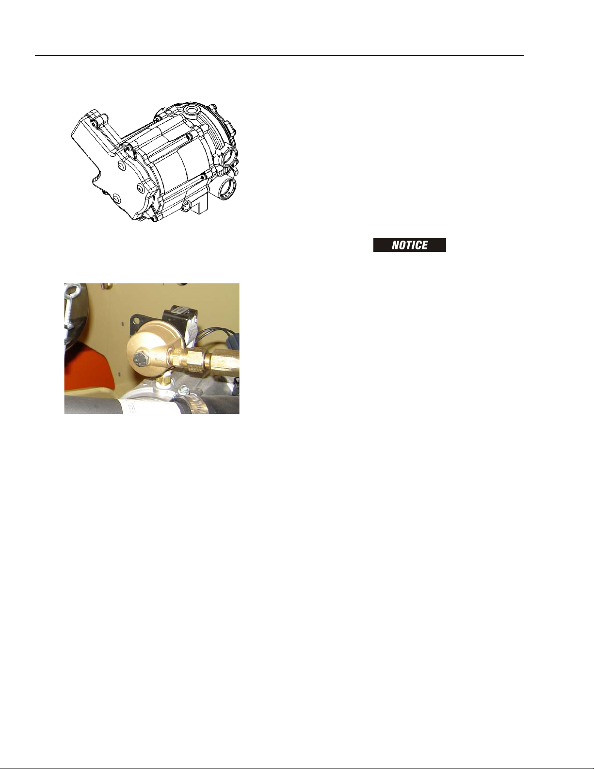
SECTION 1 - SPECIFICATIONS
18. Electronic Pressure Regulator (LP only)
Interval - 3 Months or 150 hours of operation
Comments - Drain oil build up. Refer to Draining
Oil Build Up From The Propane Regulator
19. Fuel Filter (Propane) - GM Engine
Draining Oil Build Up From The Propane Regulator
During the course of normal operation oils may build
inside the primary and secondary chambers of the propane pressure regulator. These oils may be a result of
poor fuel quality, contamination of the fuel supply
chain, or regional variation in the make up of the fuel. If
the build up of the oil is significant this can effect the
operation of the fuel control system. Refer to Section
1.11, Operator Maintenance for maintenance intervals.
More frequent draining may be required if the fuel supply has been contaminated.
FOR BEST RESULTS WARM THE ENGINE TO OPERATING TEMPERATURE BEFORE DRAINING. THIS WILL ALLOW THE OILS TO
BE LIQUID AND FLOW FREELY FROM THE REGULATOR.
1. Move the equipment to a well ventilated area.
Ensure there are no external ignition sources.
2. Start the engine and bring to operating temperature.
3. With the engine running, close the manual tank
valve and run the engine out of fuel.
4. Push in the Emergency Switch once the engine
stops.
Interval - 3 Months or 150 hours of operation
Comments - Replace filter. Refer to Propane Fuel
Filter Replacement
1-10 – JLG Lift – 3121139
Page 27

SECTION 1 - SPECIFICATIONS
1. Electric Lock Off Solenoid
2. Mounting Plate
3. Housing Seal
4. Filter Magnet
5. Filter Housing
6. Seal
7. Electrical Connector
8. Fuel Outlet
9. O-ring
10. Filter
11. Fuel Inlet
12. Retaining Bolt
Figure 1-2. Filter Lock Assembly
5. Disconnect the electrical connection to the LPG fuel
temperature sensor in the auxiliary fuel port of the
EPR.
6. Remove the retainer clip for the LPG fuel temperature sensor and remove the sensor from the regulator body.
Propane Fuel Filter Replacement
NOTE: Have a small container ready to collect oil that will
drain freely from the regulator at this point.
7. Once all of the oil has been drained, reinstall the
LPG fuel temperature sensor and reconnect the
electrical connector.
8. Open the fuel tank manual valve.
9. Start the engine and verify all connections are
secure.
10. Dispose of any drained oil in a safe and proper fashion.
REMOVAL
1. Relieve the propane fuel system pressure. Refer to
Propane Fuel System Pressure Relief.
2. Disconnect the negative battery cable.
3. Slowly loosen the Filter housing retaining bolt and
remove it.
4. Pull the filter housing from the Electric lock off
assembly.
5. Locate Filter magnet and remove it.
6. Remove the filter from the housing.
7. Remove and discard the housing seal.
8. Remove and discard the retaining bolt seal.
9. Remove and discard mounting plate to lock off O-
ring seal.
3121139 – JLG Lift – 1-11
Page 28

SECTION 1 - SPECIFICATIONS
Figure 1-3. Serial Number Locations
INSTALLATION
BE SURE TO REINSTALL THE FILTER MAGNET INTO THE HOUSING BEFORE INSTALLING NEW SEAL
1. Install the mounting plate to lock off O-ring seal.
2. Install the retaining bolt seal.
3. Install the housing seal.
4. Drop the magnet into the bottom of the filter hous-
ing.
5. Install the filter into the housing.
6. Install the retaining bolt into the filter housing.
7. Install the filter up to the bottom of the electric lock
off.
8. Tighten the filter retaining bolt to 106 in lbs (12 Nm).
9. Open manual shut-off valve. Start the vehicle and
leak check the propane fuel system at each serviced
fitting. Refer to Propane Fuel System Leak Test.
Propane Fuel System Pressure Relief
THE PROPANE FUEL SYSTEM OPERATES AT PRESSURES UP TO
312 PSI (21.5 BAR). TO MINIMIZE THE RISK OF FIRE AND PERSONAL INJURY, RELIEVE THE PROPANE FUEL SYSTEM PRESSURE (WHERE APPLICABLE) BEFORE SERVICING THE
PROPANE FUEL SYSTEM COMPONENTS.
To relieve propane fuel system pressure:
1.Close the manual shut-off valve on the propane fuel
tank.
2. Start and run the vehicle until the engine stalls.
3. Turn the ignition switch OFF.
RESIDUAL VAPOR PRESSURE WILL BE PRESENT IN THE FUEL
SYSTEM. ENSURE THE WORK AREA IS WELL VENTILATED
BEFORE DISCONNECTING ANY FUEL LINE.
1.12 SERIAL NUMBER LOCATION
A serial number plate is affixed to the left rear side of the
frame. If the serial number plate is damaged or missing,
the machine serial number is stamped on the left side of
the frame.
1-12 – JLG Lift – 3121139
Page 29

SECTION 1 - SPECIFICATIONS
Figure 1-4. Torque Chart (SAE Fasteners - Sheet 1 of 3)
3121139 – JLG Lift – 1-13
Page 30

SECTION 1 - SPECIFICATIONS
Figure 1-5. Torque Chart (SAE Fasteners - Sheet 2 of 3)
1-14 – JLG Lift – 3121139
Page 31

SECTION 1 - SPECIFICATIONS
Figure 1-6. Torque Chart (SAE Fasteners - Sheet 3 of 3)
3121139 – JLG Lift – 1-15
Page 32

SECTION 1 - SPECIFICATIONS
Figure 1-7. Torque Chart (METRIC Fasteners - Sheet 1 of 3)
1-16 – JLG Lift – 3121139
Page 33

SECTION 1 - SPECIFICATIONS
Figure 1-8. Torque Chart (METRIC Fasteners - Sheet 2 of 3))
3121139 – JLG Lift – 1-17
Page 34

SECTION 1 - SPECIFICATIONS
Figure 1-9. Torque Chart (METRIC Fasteners - Sheet 3 of 3)
1-18 – JLG Lift – 3121139
Page 35

SECTION 2. GENERAL
SECTION 2 - GENERAL
2.1 MACHINE PREPARATION, INSPECTION, AND MAINTENANCE
General
This section provides the necessary information needed
by those personnel that are responsible to place the
machine in operation readiness and maintain its safe
operating condition. For maximum service life and safe
operation, ensure that all the necessary inspections and
maintenance have been completed before placing the
machine into service.
Preparation, Inspection, and Maintenance
It is important to establish and conform to a comprehensive inspection and preventive maintenance program. The
following table outlines the periodic machine inspections
and maintenance recommended by JLG Industries, Inc.
Consult your national, regional, or local regulations for further requirements for aerial work platforms. The frequency
of inspections and maintenance must be increased as
environment, severity and frequency of usage requires.
Pre-Start Inspection
It is the User’s or Operator’s primary responsibility to perform a Pre-Start Inspection of the machine prior to use
daily or at each change of operator. Reference the Operator’s and Safety Manual for completion procedures for the
Pre-Start Inspection. The Operator and Safety Manual
must be read in its entirety and understood prior to performing the Pre-Start Inspection.
Pre-Delivery Inspection and Frequent Inspection
The Pre-Delivery Inspection and Frequent Inspection shall
be performed by a qualified JLG equipment mechanic.
JLG Industries, Inc. recognizes a qualified JLG equipment
mechanic as a person who, by possession of a recognized degree, certificate, extensive knowledge, training, or
experience, has successfully demonstrated the ability and
proficiency to service, repair, and maintain the subject
JLG product model.
The Pre-Delivery Inspection and Frequent Inspection procedures are performed in the same manner, but at different times. The Pre-Delivery Inspection shall be performed
prior to each sale, lease, or rental delivery. The Frequent
Inspection shall be accomplished for each machine in service for 3 months or 150 hours (whichever comes first);
out of service for a period of more than 3 months; or when
purchased used. The frequency of this inspection must be
increased as environment, severity and frequency of
usage requires.
Reference the JLG Pre-Delivery and Frequent Inspection
Form and the Inspection and Preventative Maintenance
Schedule for items requiring inspection during the performance of these inspections. Reference the appropriate
areas of this manual for servicing and maintenance procedures.
Annual Machine Inspection
The Annual Machine Inspection must be performed by a
Factory-Certified Service Technician on an annual basis,
no later than thirteen (13) months from the date of the
prior Annual Machine Inspection. JLG Industries, Inc. recognizes a Factory-Certified Service Technician as a person who has successfully completed the JLG Service
Training School for the subject JLG product model. Reference the machine Service and Maintenance Manual and
appropriate JLG inspection form for performance of this
inspection.
Reference the JLG Annual Machine Inspection Form and
the Inspection and Preventative Maintenance Schedule for
items requiring inspection during the performance of this
inspection. Reference the appropriate areas of this manual for servicing and maintenance procedures.
For the purpose of receiving safety-related bulletins, it is
important that JLG Industries, Inc. has updated ownership
information for each machine. When performing each
Annual Machine Inspection, notify JLG Industries, Inc. of
the current machine ownership.
Preventative Maintenance
In conjunction with the specified inspections, maintenance shall be performed by a qualified JLG equipment
mechanic. JLG Industries, Inc. recognizes a qualified JLG
equipment mechanic as a person who, by possession of a
recognized degree, certificate, extensive knowledge, training, or experience, has successfully demonstrated the
ability and proficiency to service, repair, and maintain the
subject JLG product model.
Reference the Preventative Maintenance Schedule and
the appropriate areas of this manual for servicing and
maintenance procedures. The frequency of service and
maintenance must be increased as environment, severity
and frequency of usage requires.
3121139 – JLG Lift – 2-1
Page 36

SECTION 2 - GENERAL
Table 2-1. Inspection and Maintenance
Ty pe Frequency
Pre-Start Inspection Prior to use each day; or
At each Operator change.
Pre-Delivery Inspec-
tion
Frequent Inspection In service for 3 months or 150 hours,
Annual Machine
Inspection
Preventative
Maintenance
Prior to each sale, lease, or
rental delivery.
whichever comes first; or
Out of service for a period of more than 3
months; or
purchased used.
Annually, no later than 13 months from
the date of the prior inspection.
At intervals as specified in the Ser vice
and Maintenance Manual.
2.2 SERVICE AND GUIDELINES
General
The following information is provided to assist you in the
use and application of servicing and maintenance procedures contained in this book.
Safety and Workmanship
Your safety, and that of others, is the first consideration
when engaging in the maintenance of equipment. Always
be conscious of weight. Never attempt to move heavy
parts without the aid of a mechanical device. Do not allow
heavy objects to rest in an unstable position. When raising
a portion of the equipment, ensure that adequate support
is provided.
Cleanliness
1. The most important single item in preserving the
long service life of a machine is to keep dirt and foreign materials out of the vital components. Precautions have been taken to safeguard against this.
Shields, covers, seals, and filters are provided to
keep air, fuel, and oil supplies clean; however, these
items must be maintained on a scheduled basis in
order to function properly.
Primary
Responsibility
User or Operator User or Operator Operation and Safety Manual
Owner, Dealer, or User Qualified JLG
Owner, Dealer, or User Qualified JLG
Owner, Dealer, or User Factory-Trained
Owner, Dealer, or User Qualified JLG
2. At any time when air, fuel, or oil lines are disconnected, clear adjacent areas as well as the openings
and fittings themselves. As soon as a line or component is disconnected, cap or cover all openings to
prevent entry of foreign matter.
3. Clean and inspect all parts during servicing or maintenance, and assure that all passages and openings
are unobstructed. Cover all parts to keep them
clean. Be sure all parts are clean before they are
installed. New parts should remain in their containers until they are ready to be used.
Service
Qualification
Mechanic
Mechanic
Service Technician
(Recommended)
Mechanic
Reference
Service and Maintenance
Manual and applicable JLG
inspection form.
Service and Maintenance
Manual and applicable JLG
inspection form.
Service and Maintenance
Manual and applicable JLG
inspection form.
Service and Maintenance
Manual
Components Removal and Installation
1. Use adjustable lifting devices, whenever possible, if
mechanical assistance is required. All slings (chains,
cables, etc.) should be parallel to each other and as
near perpendicular as possible to top of part being
lifted.
2. Should it be necessary to remove a component on
an angle, keep in mind that the capacity of an eyebolt or similar bracket lessens, as the angle between
the supporting structure and the component
becomes less than 90 degrees.
3. If a part resists removal, check to see whether all
nuts, bolts, cables, brackets, wiring, etc., have been
removed and that no adjacent parts are interfering.
2-2 – JLG Lift – 3121139
Page 37

SECTION 2 - GENERAL
Component Disassembly and Reassembly
When disassembling or reassembling a component, complete the procedural steps in sequence. Do not partially
disassemble or assemble one part, then start on another.
Always recheck your work to assure that nothing has been
overlooked. Do not make any adjustments, other than
those recommended, without obtaining proper approval.
Pressure-Fit Parts
When assembling pressure-fit parts, use an anti-seize or
molybdenum disulfide base compound to lubricate the
mating surface.
Bearings
1. When a bearing is removed, cover it to keep out dirt
and abrasives. Clean bearings in nonflammable
cleaning solvent and allow to drip dry. Compressed
air can be used but do not spin the bearing.
2. Discard bearings if the races and balls (or rollers)
are pitted, scored, or burned.
3. If bearing is found to be serviceable, apply a light
coat of oil and wrap it in clean (waxed) paper. Do not
unwrap reusable or new bearings until they are
ready to install.
4. Lubricate new or used serviceable bearings before
installation. When pressing a bearing into a retainer
or bore, apply pressure to the outer race. If the bearing is to be installed on a shaft, apply pressure to the
inner race.
Gaskets
Check that holes in gaskets align with openings in the
mating parts. If it becomes necessary to hand-fabricate a
gasket, use gasket material or stock of equivalent material
and thickness. Be sure to cut holes in the right location, as
blank gaskets can cause serious system damage.
2. Unless specific torque requirements are given within
the text, standard torque values should be used on
heat-treated bolts, studs, and steel nuts, in accordance with recommended shop practices. (See
Torque Chart Section 1.)
Hydraulic Lines and Electrical Wiring
Clearly mark or tag hydraulic lines and electrical wiring, as
well as their receptacles, when disconnecting or removing
them from the unit. This will assure that they are correctly
reinstalled.
Hydraulic System
1. Keep the system clean. If evidence of metal or rubber particles are found in the hydraulic system, drain
and flush the entire system.
2. Disassemble and reassemble parts on clean work
surface. Clean all metal parts with non-flammable
cleaning solvent. Lubricate components, as
required, to aid assembly.
Lubrication
Service applicable components with the amount, type,
and grade of lubricant recommended in this manual, at
the specified intervals. When recommended lubricants are
not available, consult your local supplier for an equivalent
that meets or exceeds the specifications listed.
Battery
Clean battery, using a non-metallic brush and a solution of
baking soda and water. Rinse with clean water. After
cleaning, thoroughly dry battery and coat terminals with
an anti corrosion compound.
Lubrication and Servicing
Components and assemblies requiring lubrication and
servicing are shown in the Lubrication Chart in Section 1.
Bolt Usage and Torque Application
SELF LOCKING FASTENERS, SUCH AS NYLON INSERT AND
THREAD DEFORMING LOCKNUTS, ARE NOT INTENDED TO BE
REINSTALLED AFTER REMOVAL.
1. Always use new replacement hardware when installing locking fasteners. Use bolts of proper length. A
bolt which is too long will bottom before the head is
tight against its related part. If a bolt is too short,
there will not be enough thread area to engage and
hold the part properly. When replacing bolts, use
only those having the same specifications of the
original, or one which is equivalent.
3121139 – JLG Lift – 2-3
Page 38

SECTION 2 - GENERAL
2.3 LUBRICATION AND INFORMATION
Hydraulic System
1. The primary enemy of a hydraulic system is contamination. Contaminants enter the system by various
means, e.g., using inadequate hydraulic oil, allowing
moisture, grease, filings, sealing components, sand,
etc., to enter when performing maintenance, or by
permitting the pump to cavitate due to insufficient
system warm-up or leaks in the pump supply (suction) lines.
2. The design and manufacturing tolerances of the
component working parts are very close, therefore,
even the smallest amount of dirt or foreign matter
entering a system can cause wear or damage to the
components and generally results in faulty operation. Every precaution must be taken to keep
hydraulic oil clean, including reserve oil in storage.
Hydraulic system filters should be checked,
cleaned, and/or replaced as necessary, at the specified intervals required in the Lubrication Chart in
Section 1. Always examine filters for evidence of
metal particles.
3. Cloudy oils indicate a high moisture content which
permits organic growth, resulting in oxidation or corrosion. If this condition occurs, the system must be
drained, flushed, and refilled with clean oil.
4. It is not advisable to mix oils of different brands or
types, as they may not contain the same required
additives or be of comparable viscosities. Good
grade mineral oils, with viscosities suited to the
ambient temperatures in which the machine is operating, are recommended for use.
Changing Hydraulic Oil
1. Filter elements must be changed after the first 50
hours of operation and every 300 hours (unless
specified otherwise) thereafter. If it is necessary to
change the oil, use only those oils meeting or
exceeding the specifications appearing in this manual. If unable to obtain the same type of oil supplied
with the machine, consult local supplier for assistance in selecting the proper equivalent. Avoid mixing petroleum and synthetic base oils. JLG
Industries recommends changing the hydraulic oil
annually.
2. Use every precaution to keep the hydraulic oil clean.
If the oil must be poured from the original container
into another, be sure to clean all possible contaminants from the service container. Always clean the
mesh element of the filter and replace the cartridge
any time the system oil is changed.
3. While the unit is shut down, a good preventive maintenance measure is to make a thorough inspection
of all hydraulic components, lines, fittings, etc., as
well as a functional check of each system, before
placing the machine back in service.
Lubrication Specifications
Specified lubricants, as recommended by the component
manufacturers, are always the best choice, however,
multi-purpose greases usually have the qualities which
meet a variety of single purpose grease requirements.
Should any question arise, regarding the use of greases in
maintenance stock, consult your local supplier for evaluation. Refer to Section 1 for an explanation of the lubricant
key designations appearing in the Lubrication Chart.
NOTE: Metal particles may appear in the oil or filters of new
machines due to the wear-in of meshing components.
Hydraulic Oil
Refer to Section 1 for recommendations for viscosity
ranges.
2.4 CYLINDER DRIFT TEST
Maximum acceptable cylinder drift is to be measured
using the following methods.
Platform Drift
Measure the drift of the platform to the ground. Lower
booms (if equipped) slightly elevated, upper boom fully
extended with the rated load in the platform and power off.
Maximum allowable drift is 2 inches (5 cm) in 10 minutes.
If the machine does not pass this test, proceed with the
following.
2-4 – JLG Lift – 3121139
Page 39

SECTION 2 - GENERAL
Cylinder Drift
Table 2-2. Cylinder Drift
Cylinder Bore Diameter
inches mm inches mm
3 76.2 0.026 0.66
3.5 89 0.019 0.48
4 101.6 0.015 0.38
5 127 0.009 0.22
6 152.4 0.006 0.15
7 177.8 0.005 0.13
8 203.2 0.0038 0.10
9 228.6 0.0030 0.08
Drift is to be measured at the cylinder rod with a calibrated
dial indicator. The cylinder oil must be at ambient temperature and temperature stabilized.
The cylinder must have the normal load, which is the normal platform load applied.
If the cylinder passes this test, it is acceptable.
NOTE: This information is based on 6 drops per minute cyl-
inder leakage.
Max. Acceptable Drift
in 10 Minutes
c. Rusting of the pin in the bearing area.
4. Re-assembly of pinned joints using filament wound
bearings.
a. Housing should be blown out to remove all dirt
and debris...bearings and bearing housings
must be free of all contamination.
b. Bearing / pins should be cleaned with a solvent
to remove all grease and oil...filament wound
bearing are a dry joint and should not be lubricated.
c. Pins should be inspected to ensure it is free of
burrs, nicks, and scratches which would damage the bearing during installation and operation.
2.6 WELDING ON JLG EQUIPMENT
NOTE: This instruction applies to repairs, or modifications to
the machine and to welding performed from the
machine on an external structure, or component,
Do the Following When Welding on JLG Equipment
• Disconnect the battery.
• Disconnect the moment pin connection (where fitted)
• Ground only to structure being welded.
2.5 PINS AND COMPOSITE BEARING REPAIR GUIDELINES
Filament wound bearings.
1. Pinned joints should be disassembled and
inspected if the following occurs:
a. Excessive sloppiness in joints.
b. Noise originating from the joint during operation.
2. Filament wound bearings should be replaced if any
of the following is observed:
a. Frayed or separated fibers on the liner surface.
b. Cracked or damaged liner backing.
c. Bearings that have moved or spun in their hous-
ing.
d. Debris embedded in liner surface.
3. Pins should be replaced if any of the following is
observed (pin should be properly cleaned prior to
inspection):
a. Detectable wear in the bearing area.
b. Flaking, pealing, scoring, or scratches on the pin
surface.
Do NOT Do the Following When Welding on JLG Equipment
• Ground on frame and weld on any other area than the
chassis.
• Ground on turntable and weld on any other area than
the turntable.
• Ground on the platform/support and weld on any other
area than the platform/support.
• Ground on a specific boom section and weld on any
other area than that specific boom section.
• Allow pins, wear pads, wire ropes, bearings, gearing,
seals, valves, electrical wiring, or hoses to be between
the grounding position and the welded area.
FAILURE TO COMPLY WITH THE ABOVE REQUIREMENTS MAY
RESULT IN COMPONENT DAMAGE (I.E. ELECTRONIC MODULES,
SWING BEARING, COLLECTOR RING, BOOM WIRE ROPES ETC.)
3121139 – JLG Lift – 2-5
Page 40

SECTION 2 - GENERAL
Table 2-3. Inspection and Preventive Maintenance Schedule
INTERVAL
AREA
Boom Assembly
Boom Weldments 1,2,4 1,2,4
Hose/Cable Carrier Installations 1,2,9,12 1,2,9,12
Pivot Pins and Pin Retainers 1,2 1,2
Sheaves, Sheave Pins 1,2 1,2
Bearings 1,2 1,2
Wear Pads 1,2 1,2
Covers or Shields 1,2 1,2
Extend/Retract Chain or Cable Systems 1,2,3 1,2,3
Platform Assembly
Platform 1,2 1,2
Railing 1,2 1 1,2
Gate 511,5
Floor 1,2 1 1,2
Rotator 9,5 15
Lanyard Anchorage Point 2 1,2,10 1,2,10
Turntable Assembly
Swing Bearing or Worm Gear 1,2,14 1,2,3,13,14
Oil Coupling 9
Swing Drive System 11 11
Turntable Lock 1,2,5 1,2,5
Hood, Hood Props, Hood Latches 51,2,5
Chassis Assembly
Tires 1 16,17 16,17,18 16,17,18
Wheel Nuts/Bolts 115 1515
Wheel Bearings 14,24
Oscillating Axle/Lockout Cylinder Systems 5,8
Outrigger or Extendable Axle Systems 5,8 5,8
Steer Components
Drive Motors
Torque Hubs 11 11
Functions/Controls
Platform Controls 55 66
Pre-Start
Inspection
9
9
9
9
9
1
Preventive
Maintenance
Weekly
Monthly
Preventive
Maintenance
Pre-Delivery
or Frequent
Inspection
2
3
Annual
(Yearly)
Inspection
4
Every 2
Years
2-6 – JLG Lift – 3121139
Page 41

SECTION 2 - GENERAL
Table 2-3. Inspection and Preventive Maintenance Schedule
INTERVAL
AREA
Pre-Start
Inspection
1
Preventive
Maintenance
Weekly
Monthly
Preventive
Maintenance
Pre-Delivery
or Frequent
Inspection
2
3
Ground Controls 55 66
Function Control Locks, Guards, or Detents 1,5 1,5 5 5
Footswitch 1,5 5 5
Emergency Stop Switches (Ground & Platform) 555
Function Limit or Cutout Switch Systems 55
Capacity Indicator 5
Drive Brakes 5
Swing Brakes 5
Boom Synchronization/Sequencing Systems 5
Manual Descent or Auxiliary Power 55
Power System
9
Engine Idle, Throttle, and RPM 33
Engine Fluids (Oil, Coolant, Fuel) 11 9,11 11 11
Air/Fuel Filter 1,7 7 7
Exhaust System 1,9 9 9
Batteries 51,9 19
Battery Fluid 11 11 11
Battery Charger 55
Fuel Reservoir, Cap, and Breather 11,9 2 1,5 1,5
Hydraulic/Electric System
9
Hydraulic Pumps 1,9 1,2,9
Hydraulic Cylinders 1,9,7 2 1,2,9 1,2,9
Cylinder Attachment Pins and Pin Retainers 1,9 1,2 1,2
Hydraulic Hoses, Lines, and Fittings 1,9 12 1,2,9,12 1,2,9,12
Hydraulic Reservoir, Cap, and Breather 11 1,9 2 1,5 1,5 24
Hydraulic Filter 1,9 7 7
Hydraulic Fluid 11 7,11 7,11
Electrical Connections 12020
Instruments, Gauges, Switches, Lights, Horn 15,23
General
Operators and Safety Manuals in Storage Box 21 21 21
ANSI and EMI Manuals/Handbooks Installed 21
Capacity Decals Installed, Secure, Legible 21 21 21
All Decals/Placards Installed, Secure, Legible 21 21 21
Annual
(Yearly)
Inspection
4
Every 2
Years
3121139 – JLG Lift – 2-7
Page 42

SECTION 2 - GENERAL
Table 2-3. Inspection and Preventive Maintenance Schedule
INTERVAL
AREA
Pre-Start
Inspection
1
Preventive
Maintenance
Weekly
Monthly
Preventive
Maintenance
Pre-Delivery
or Frequent
Inspection
2
3
Walk-Around Inspection Performed 21
Annual Machine Inspection Due 21
No Unauthorized Modifications or Additions 21 21
All Relevant Safety Publications Incorporated 21 21
General Structural Condition and Welds 2,4 2,4
All Fasteners, Pins, Shields, and Covers 1,2 1,2
Grease and Lubricate to Specifications 22 22
Function Test of All Systems 21 21 21, 22
Paint and Appearance 77
Stamp Inspection Date on Frame 22
Notify JLG of Machine Ownership 22
Footnotes:
1
Prior to use each day; or at each Operator change
2
Prior to each sale, lease, or delivery
3
In service for 3 months or 150 Hours; or Out of service for 3 months or more; or Purchased use d
4
Annually, no later than 13 months from the date of the prior inspection
Performance Codes:
1 - Check for proper and secure installation
2 - Visual inspection for damage, cracks, distortion or exc essive wear
3 - Check for proper adjustment
4 - Check for cracked or broken welds
5 - Operates Properly
6 - Returns to neutral or "off" position when released
7 - Clean and free of debris
8 - Interlocks function properly
9 - Check for signs of leakage
10 - Decals installed and legible
11 - Check for proper fluid level
12 - Check for chafing and proper routing
13 - Check for proper tolerances
14 - Properly lubricated
15 - Torqued to proper specification
16 - No gouges, excessive wear, or cords showing
17 - Properly inflated and seated around rim
18 - Proper and authorized components
19 - Fully charged
20 - No loose connections, corrosion, or abrasions
21 - Verify
22 - Perform
23 - Sealed Properly
24 - Drain, Clean, Refill
Annual
(Yearly)
Inspection
4
Every 2
Years
2-8 – JLG Lift – 3121139
Page 43

SECTION 2 - GENERAL
Figure 2-1. Engine Operating Temperature Specifications - Deutz
4150548 D
3121139 – JLG Lift – 2-9
Page 44

SECTION 2 - GENERAL
Figure 2-2. Engine Operating Temperature Specifications - Ford
4150548 D
2-10 – JLG Lift – 3121139
Page 45

SECTION 2 - GENERAL
Figure 2-3. Engine Operating Temperature Specifications - Caterpillar
4150548 D
3121139 – JLG Lift – 2-11
Page 46

SECTION 2 - GENERAL
Figure 2-4. Engine Operating Temperature Specifications - GM
4150548 D
2-12 – JLG Lift – 3121139
Page 47

SECTION 3 - CHASSIS & TURNTABLE
SECTION 3. CHASSIS & TURNTABLE
3.1 TIRES & WHEELS
Tire Inflation
The air pressure for pneumatic tires must be equal to
the air pressure that is stenciled on the side of the JLG
product or rim decal for safe and proper operational
characteristics.
Tire Damage
For pneumatic tires, JLG Industries, Inc. recommends that
when any cut, rip, or tear is discovered that exposes sidewall or tread area cords in the tire, measures must be
taken to remove the JLG product from service immediately. Arrangements must be made for replacement of the
tire or tire assembly.
For polyurethane foam filled tires, JLG Industries, Inc. recommends that when any of the following are discovered,
measures must be taken to remove the JLG product from
service immediately and arrangements must be made for
replacement of the tire or tire assembly.
• a smooth, even cut through the cord plies which
exceeds 3 inches (7.5 cm) in total length
• any tears or rips (ragged edges) in the cord plies which
exceeds 1 inch (2.5 cm) in any direction
• any punctures which exceed 1 inch in diameter
• any damage to the bead area cords of the tire
Tire Replacement
JLG recommends a replacement tire be the same size, ply
and brand as originally installed on the machine. Please
refer to the JLG Parts Manual for the part number of the
approved tires for a particular machine model. If not using
a JLG approved replacement tire, we recommend that
replacement tires have the following characteristics:
• Equal or greater ply/load rating and size of original
• Tire tread contact width equal or greater than original
• Wheel diameter, width, and offset dimensions equal to
the original
Unless specifically approved by JLG Industries Inc. do not
replace a foam filled or ballast filled tire assembly with a
pneumatic tire. When selecting and installing a replacement tire, ensure that all tires are inflated to the pressure
recommended by JLG. Due to size variations between
tire brands, both tires on the same axle should be the
same.
Wheel Replacement
The rims installed on each product model have been
designed for stability requirements which consist of track
width, tire pressure, and load capacity. Size changes such
as rim width, center piece location, larger or smaller diameter, etc., without written factory recommendations, may
result in an unsafe condition regarding stability.
If a tire is damaged but is within the above noted criteria,
the tire must be inspected on a daily basis to insure the
damage has not propagated beyond the allowable criteria.
3121139 – JLG Lift – 3-1
Page 48

SECTION 3 - CHASSIS & TURNTABLE
Table 3-1. Wheel Torque Chart
TORQUE SEQUENCE
1st Stage 2nd Stage 3rd Stage
70 ft. lbs.
(95 Nm)
170 ft. lbs.
(225 Nm)
300 ft. lbs.
(405 Nm)
Wheel Installation
It is extremely important to apply and maintain proper
wheel mounting torque.
WHEEL NUTS MUST BE INSTALLED AND MAINTAINED AT THE
PROPER TORQUE TO PREVENT LOOSE WHEELS, BROKEN STUDS,
AND POSSIBLE DANGEROUS SEPARATION OF WHEEL FROM THE
AXLE. BE SURE TO USE ONLY THE NUTS MATCHED TO THE CONE
ANGLE OF THE WHEEL.
Tighten the lug nuts to the proper torque to prevent
wheels from coming loose. Use a torque wrench to tighten
the fasteners. If you do not have a torque wrench, tighten
the fasteners with a lug wrench, then immediately have a
service garage or dealer tighten the lug nuts to the proper
torque. Over-tightening will result in breaking the studs or
permanently deforming the mounting stud holes in the
wheels. The proper procedure for attaching wheels is as
follows:
1. Start all nuts by hand to prevent cross threading. DO
NOT use a lubricant on threads or nuts.
2. Tighten nuts in the following sequence:
3.2 WHEEL DRIVE ASSEMBLY, 2WD
Removal and Disassembly
NOTE: The drive motor and/or drive brake can be removed
through the axle flange as part of the wheel drive
assembly or they can be removed separately
through the bottom of the frame while leaving the
torque hub bolted to the axle.
1. Use a jack to lift the frame enough so the tire and
wheel assembly is off of the ground. Place blocking
strong enough to support the weight of the machine
under the frame and remove the jack.
NOTE: The pneumatic tire & wheel assembly weighs
approximately 269 lbs. (122 kg). The foam-filled tire
& wheel assembly weighs approximately 544 lbs.
(247.25 kg).
2. Remove the tire and wheel assembly.
3. Through the access holes in the axle, tag and dis-
connect the hydraulic lines running to the drive
motor and drive brake. Cap or plug all openings to
ensure no dirt enters the hydraulic system.
3. The tightening of the nuts should be done in stages.
Following the recommended sequence, tighten nuts
per wheel torque chart.
NOTE: The torque hub, drive brake, and drive motor assem-
bly weighs approximately 275 lbs. (125 kg).
4. Use a supporting device capable of handling the
weight of the torque hub, drive brake, and drive
motor and unbolt the torque hub from the frame.
Remove the entire assembly from the machine.
5. Remove the nuts and washers that secure the drive
motor to the torque hub and drive brake and remove
the drive motor. Remove and discard the o-ring
between the drive motor and drive brake.
6. Remove the drive brake from the torque hub.
Remove and discard the o-ring between the drive
brake and torque hub.
7. If necessary, remove the studs from the torque hub.
4. Wheel nuts should be torqued after first 50 hours of
operation and after each wheel removal. Check
torque every 3 months or 150 hours of operation.
3-2 – JLG Lift – 3121139
Page 49

SECTION 3 - CHASSIS & TURNTABLE
Figure 3-1. Torque Hub Installation - 2WD
Assembly and Installation
1. If re-installing the old studs or installing new ones,
coat the threads of the studs with Loctite #242
before screwing them into the torque hub.
2. Install a new o-ring between the drive brake and
torque hub and slide the drive brake over the studs
with the brake port positioned as shown.
3. Install a new o-ring between the drive brake and
drive motor and slide the drive motor over the studs.
Install the washers and nuts to secure the assembly
together and torque the nuts to 75 ft. lbs. (102 Nm).
4. Place the torque hub flange against the mounting
flange on the axle and fasten it in place with the bolts
and washers. Torque the bolts to 220 ft. lbs. (298
Nm).
5. Install the tire and wheel assembly.
3121139 – JLG Lift – 3-3
Page 50

SECTION 3 - CHASSIS & TURNTABLE
3.3 DRIVE MOTOR - 2WD (PRIOR TO S/N
83331)
Replacing the Drive Shaft Seal
1. Remove snap ring.
5. Assemble the snap ring.
2. Change the shaft seal and check its sliding surface
(drive shaft) and housing, grease the sealing ring.
3. Be careful while you seal the drive shaft, use an
adhesive tape.
6. Assemble the snap ring in the correct position.
NOTE: This description shows how to change the drive shaft
sealing ring but isn’t the way of serial assembly. the
sealing ring is assembled together with the taper
roller bearing from inside the pump housing normally
to get a secure condition. If you decide to repair the
pump in the shown way be very careful while handling so that the drive shaft will not be damaged during disassembly of the shaft sealing ring.
4. Assemble the sealing ring, fitting tool holds the correct position of the sealing ring in the pump housing.
3-4 – JLG Lift – 3121139
Page 51

SECTION 3 - CHASSIS & TURNTABLE
Disassembly
1. Disassemble the pilot valve.
2. Mark the position of the port plate and remove the
socket screw of the port plate.
4. Remove the O-ring.
5. Disassemble the taper roller bearing (near by port
plate).
3. Remove the port plate together with the valve plate
(hold the valve plate so that the plate can’t fall
down).
6. Remove the adjustment shim.
3121139 – JLG Lift – 3-5
Page 52

SECTION 3 - CHASSIS & TURNTABLE
7. Unscrew the cap nut and remove it.
8. Loosen the fixing nut of the stopper max flow and
disassemble it.
10. Disassemble the rotary group in horizontal position.
11. Disassemble the stopper - max flow.
9. Turn in the stopper max flow to get swivel angle
zero.
12. Remove the threaded pin (stopper - max flow).
13. Disassemble the plug.
3-6 – JLG Lift – 3121139
Page 53

SECTION 3 - CHASSIS & TURNTABLE
14. Disassemble the control plate while moving the
swash plate.
15. The swash plate must be lifted a little bit to disassemble the piston rod.
17. Remove the spring.
18. Remove both bearing shells.
16. Disassemble the swash plate.
19. Remove the drive shaft.
20. Disassemble the snap ring.
3121139 – JLG Lift – 3-7
Page 54

SECTION 3 - CHASSIS & TURNTABLE
21. Disassemble the sealing ring.
22. The external front bearing ring is pulled out of the
pump housing.
bearing inside the port plate. Take care of the surface of the port plate.
25. The spring has additional pretension while you disassemble the three pressure pins inside the cylinder.
23. Remove the O-ring. Lifting of the valve plate isn’t
shown.
24. A usual commercial bearing puller is used to disassemble the external bearing ring of the taper roller
3-8 – JLG Lift – 3121139
Page 55

SECTION 3 - CHASSIS & TURNTABLE
Assembly
1. Assemble the variable displacement pump in
reverse order.
2. Measurement of the taper roller bearing pretension
(see adjustment figure).
NOTE: There is a correct connection of the piston rod and
swash plate.
4. Pumps anti-clockwise driven must have a position of
the valve plate 4° decentered in counter-clockwise
position.
5. Assembly of the port plate and pump housing:
NOTE: The correct position of the drilling that connects high
pressure to the control valve. Check control valve
drilling position at the pump housing and fit together.
3. Pumps clockwise driven must have a position of the
valve plate 4° out of center in the same direction
decentered like drive direction.
NOTE: Spare parts exist as clockwise and counter-clock-
wise valve plates.
3121139 – JLG Lift – 3-9
Page 56

SECTION 3 - CHASSIS & TURNTABLE
Figure 3-2. Bearing Tension
3-10 – JLG Lift – 3121139
Page 57

SECTION 3 - CHASSIS & TURNTABLE
Bias spring
Servo piston
Swashplate
Output
Shaft
Piston
Slipper
Cylinder
Block
Endcap
Shaft
Seal
Bearing
Minimum
Angle
Stop
Valv
e plate
Figure 3-3. Drive Motor Cross Section
1
2
3
1. Snap Ring
2. Support Washer
3. Shaft Seal
Figure 3-4. Removing the Shaft Seal
3.4 DRIVE MOTOR (S/N 83331 TO PRESENT)
Description
The drive motors are low to medium power, two-position
axial piston motors incorporating an integral servo piston.
They are designed for operation in both open and closed
circuit applications. The standard control is a direct acting
single line hydraulic control. The integral servo piston controls motor displacement.
The motors are spring biased to maximum displacement
and hydraulically shifted to minimum displacement. Minimum and maximum displacement can be set with fixed
internal stops. The large diameter servo piston allows
smooth acceleration and deceleration with relatively large
circuit orificing.
Shaft Seal Replacement
REMOVAL
1. Remove the snap ring (1) retaining the shaft seal
and support washer.
2. Remove the support washer (2).
3. Carefully pry out the shaft seal (3).
To avoid damaging the shaft during removal, install
a large sheet metal screw into the chuck of a slide
hammer. Drive the screw into the seal surface and
use the slide hammer to pull the seal.
4. Discard the seal.
INSPECT THE COMPONENTS
Inspect the new seal, the motor housing seal bore, and
the sealing area on the shaft for rust, wear, and contamination. Polish the shaft and clean the housing if necessary.
INSTALLATION
1. Cover the shaft splines with an installation sleeve to
protect the shaft seal during installation.
2. Install a new shaft seal with the cupped side facing
the motor. Press seal into housing until it bottoms
out. Press evenly to avoid binding and damaging
the seal.
3. Install seal support washer.
4. Install snap ring.
5. Remove the installation sleeve.
3121139 – JLG Lift – 3-11
Page 58

SECTION 3 - CHASSIS & TURNTABLE
2
6
9
11
1
4
8
10
12
5
3
7
13
(37 Nm)
27 ft.lbs.
11/16 in
(37 Nm)
27 ft.lbs.
11/16 in
(27 Nm)
20 ft.lbs.
5/8 in
1. Plug
2. Plug
3. Plug
4. O-ring
5. O-ring
6. O-ring
7. Spring
8. Spring
9. Spring
10. Washer
11. Washer
12. Shift Spool
13. Orifice Poppet
Figure 3-5. Loop Flushing Spool
Loop Flushing Valve
REMOVAL
1. Using a 11/16 in internal hex wrench remove plug
(1) and (2).
INSPECT THE COMPONENTS
Inspect new O-rings and the sealing area for rust, wear, or
contamination. Also check springs and poppet for wear.
INSTALLATION
1. Install orifice poppet (13).
2. Install shift spool (12).
3. Install spring retaining washers onto springs (10 and
11).
4. Carefully install centering springs (7, 8, and 9).
5. Install new O-rings (6, 4, and 5).
6. Using a 1/4 in hex wrench torque plug (3) to 20 ft.
lbs. (27 Nm).
7. Using a 11/16 in internal hex, torque plugs (2 and 1)
to 27 ft.lbs. (37 Nm).
2. Using a 1/4 in hex wrench remove plug (3).
3. Remove O-rings (4, 5, and 6).
4. Using pliers, remove centering springs (7, 8, and 9).
5. Remove spring retaining washers (10 and 11).
6. Remove shift spool (12).
7. Remove orifice poppet (13).
3-12 – JLG Lift – 3121139
Page 59

Troubleshooting
Item Description Action
Check oil level in reservoir
and oil supply to the motor.
Table 3-2. Excessive Noise and/or Vibration
Insufficient hydraulic fluid could lead to cavitation that woul d
cause system noise.
SECTION 3 - CHASSIS & TURNTABLE
Fill the reservoir to the proper le vel and ensure that oil supply to
the motor is adequate and the lines are unobstructed.
Check for air in the system. Air trapped within the system lines, or the motor itself, could
result in cavitation that would cause system noise.
Inspect the output shaft couplings.
Inspect the output shaft
alignment.
Hydraulic oil viscosity above
limits.
Item Description Action
Check oil level in reservoir
and oil supply to the pump.
Inspect the heat exchanger,
(if so equipped).
Check the system relief
valves.
A loose or incorrect shaft coupling will produce vib rations that
could result in system noise.
Misaligned shafts create excessive frictional vibration that
could result in system noise.
Viscosity above acceptable limits will result in cavitation that
would lead to system noise.
Table 3-3. System Operating Hot
Insufficient amount of hydraulic fluid will not meet the cooling
demands of the system.
If the heat exchanger fails, or becomes obstructed, it may not
meet the cooling demands of the system.
If a system relief valve becomes unseated for an extended
period of time or fails for any other reason, the system could
become overheated.
Ensure that all of the system lines and components are purged
of air.
Ensure that the correct coupling is used and that it fits properly
onto the shaft.
Ensure that the shafts are prop erly aligned.
Replace hydraulic oil with appropri ate fluid for operating conditions.
Fill the reservoir to the proper level.
Ensure that heat exchanger is receiving adequate ai r flow and
that the heat exchanger is in good operating con dition. Repair
or replace as necessary.
Repair or replace any malfunctionin g relief valves as applicable and verify that the loads on the machine are not excessive.
Table 3-4. Won’t Shift or Slow to Start
Item Description Action
Check the signal line to the
servo control port.
Check that the correct supply
and drain orifices are properly installed, and are not
obstructed.
Obstructed or restricted flow through the servo control sign al
lines could result in slow shift or no shift conditions within the
motor.
Supply and drain orifices determine the shift rate of the motor.
The smaller the orifice, the lo nger the time it takes to shift the
motor. Obstruction will also increase shift times.
Ensure that the signal lines are not obstructed or restricted and
that signal pressure is adequate to shift the motor.
Ensure that the proper control ori fices are installed in the motor
and verify that they are not obstructed. Clean or rep lace as
necessary.
3121139 – JLG Lift – 3-13
Page 60

SECTION 3 - CHASSIS & TURNTABLE
5
3
7
13
2
6
9
11
1
4
8
10
12
1. Plug
2. Plug
3. Plug
4. O-ring
5. O-ring
6. O-ring
7. Spring
8. Spring
9. Spring
10. Washer
11. Washer
12. Shift Spool
13. Orifice Poppet
Figure 3-6. Loop Flushing Spool
15
20
16
16
19
17
182114
14. Lock Nut
15. O-ring Plug
16. Control Line Plug
17. Control Line Plug
18. Cavity Plug
19. Drain Plug
20. Drain Plug
21. Work Port Plug
Figure 3-7. Plugs, Fittings, and Speed Sensor
Disassembly
NOTE: Removal of the endcap voids warranty.
During assembly, coat all moving parts with a film of
clean hydraulic oil. This assures that these parts will
be lubricated during start-up.
Replace all O-Rings and gaskets.
It is recommended that all O-rings be replaced.
Lightly lubricate all O-rings with clean petroleum jelly
prior to assembly.
1. Using a 11/16 in wrench remove plug (1) and (2).
2. Using a 5/8 in hex wrench remove plug (3).
3. Remove O-rings (4, 5, and 6).
4. Using pliers, remove centering springs (7, 8, and 9).
5. Remove spring retaining washers (10 and 11).
6. Remove shift spool (12).
7. Remove orifice poppet (13).
3-14 – JLG Lift – 3121139
8. Remove all fittings from the unit. Discard any O-rings
on the fittings.
9. Using an 11/16 inch hex wrench, loosen the speed
sensor lock nut (14) if equipped. Then remove the
speed sensor using a Vi inch hex wrench. Units without speed sensor have an O-ring plug (15) installed
in that location; remove it with a Va inch internal hex
wrench.
10. Using a 1/4 inch internal hex wrench, remove control
line plugs (16, 17). Discard O-rings. Using a 3 mm
hex wrench, remove cavity plug (18, if equipped with
two-line control) from X2 cavity.
11. Using a 5/16 inch internal hex wrench, remove drain
plugs (19, 20). Discard O-rings.
12. Using a 9/16 inch internal hex wrench, remove work
port plugs (21, if equipped with axial ports). Discard
O-rings.
Page 61

SECTION 3 - CHASSIS & TURNTABLE
24
22
23
22. Screw
23. End Cap
24. O-ring
Figure 3-8. End Cap
26
28
29
30
292725
25. Valve Plate
26. End Cap
27. O-ring
28. O-ring
29. Angle Stop
30. Servo Spring
Figure 3-9. Valve Plate & Rear Shaft Bearing
13. Using an 8 mm internal hex wrench, remove the
endcap screws (22).
14. Remove the endcap (23). Remove O-ring (24) from
the housing or endcap.
When the endcap screws are removed, pressure
from the servo spring will cause the endcap to bind
TAKE CARE NOT TO SCRATCH THE SURFACE OF THE VALVE
PLATE.
on the shaft. Press down on the portion of the endcap covering the servo piston and hold the endcap
level while removing.
15. Remove the valve plate (25) and timing pin (26) from
the endcap.
Each displacement has a unique valve plate. For
identification, the last two digits of the valve plate
part number are stamped on its surface.
16. Remove and discard the O-rings (27, 28).
17. Remove the rear shaft bearing (29) from the endcap
with a bearing puller.
The bearing may be difficult to remove with a puller.
Try this as an alternative: Pack the bearing cavity
with heavy grease. After the shaft is removed, insert
it into the bearing cavity and tap lightly with a soft
mallet on the splined end. The grease will force the
bearing out. Use caution not to drive the bearing
past the rear shaft journal as the bearing may
become trapped on the shaft and damaged.
3121139 – JLG Lift – 3-15
Page 62

SECTION 3 - CHASSIS & TURNTABLE
31
31. Cylinder Kit Assembly
Figure 3-10. Cylinder Kit
32
33
34
32. Snap Ring
33. Support Washer
34. Shaft Seal
Figure 3-11. Shaft Seal
38
37
36
35
35. Inner Snap Ring
36. Snap Ring
37. Bearing
38. Shaft
Figure 3-12. Shaft & Front Bearing
18. Remove minimum angle stop (29) and servo spring
(30) from the housing.
19. Turn the housing on its side and remove the cylinder
kit assembly (31). Set the assembly aside, being
careful not to scratch the running surface.
NOTE: Grooves on the surface of the cylinder kit identify its
displacement:
Table 3-5. Displacement Identifiers
# of Grooves Frame L Frame K
1 25 38
2 30 45
3 35 - -
shaft seal (34). Discard the seal.
To avoid damaging the shaft during seal removal,
install a large sheet metal screw into the chuck of a
slide hammer. Drive the screw into the seal surface
and use the slide hammer to pull the seal.
21. Remove the inner snap ring (35) and the shaft /
bearing assembly.
22. Remove the snap-ring (36) retaining the shaft front
bearing. Pull the bearing (37) off of the shaft (38).
20. Turn the housing over and remove the snap ring (32)
retaining the shaft seal and support washer. Remove
the support washer (33) and carefully pry out the
3-16 – JLG Lift – 3121139
Page 63

SECTION 3 - CHASSIS & TURNTABLE
41
42
40
Lift here
39
43
39. Swashplate
40. Servo Piston
41. Piston Seal
42. O-ring
43. Journal Bearings
Figure 3-13. Swash Plate & Servo Piston
51505253464948
474544
44. Piston
45. Slipper Retainer
46. Cylinder Block
47. Ball Guide
48. Holddown Pins
49. Retaining Ring
50. Block Spring Washer
51. Spiral Retaining Ring
52. Block Spring
53. Inner Block Spring Washer
Figure 3-14. Cylinder Kit Disassembly
23. Turn housing over and remove the swashplate (39)
by lifting on the end opposite the servo lever.
24. Remove the servo piston (40). Remove the piston
seal (41) and O-ring (42) from the servo piston. Discard the seal and O-ring.
25. Remove the journal bearings (43) from the housing.
If the bearings are to be reused, note the location
and orientation of each bearing for reassembly.
3121139 – JLG Lift – 3-17
26. Remove pistons (44) and slipper retainer (45) from
the cylinder block (46).
The pistons are not selectively fitted, however units
with high hourly usage may develop wear patterns.
Number the pistons and bores for reassembly if they
are to be reused.
27. Remove the ball guide (47), hold-down pins (48),
and retaining ring (49) from the cylinder block.
NOTE: Most repairs do not require block spring removal.
Perform this procedure only if you suspect problems
with the block spring.
RISK OF PERSONAL INJURY: COMPRESSING THE BLOCK SPRING
REQUIRES FORCE OF ABOUT 80 TO 90 LBF (350 TO 400 N). USE
A PRESS SUFFICIENT TO MAINTAIN THIS FORCE WITH REASONABLE EFFORT. ENSURE THE SPRING IS SECURE BEFORE
ATTEMPTING TO REMOVE THE SPIRAL RETAINING RING.
RELEASE THE PRESSURE SLOWLY AFTER THE RETAINING RING
IS REMOVED.
Page 64

SECTION 3 - CHASSIS & TURNTABLE
Slipper
Maximum end play
M inimum
slipper fo ot
thick ness
A
Table 3-7. Cylinder Block Measurements
Measurement L25 L30 L35 K38 K45
Minimum Cylinder Block Height (A) 50.8 (2.00) 50.8 (2.00) 50.8 (2 .00) 54.4 (2.14) 54.4 (2.14)
Cylinder Block Surface Flatness 0.002
(0.0000079)
0.002
(0.0000079)
0.002
(0.0000079)
0.002
(0.0000079)
0.002
(0.0000079)
28. Turn the block over. Using a press, apply pressure
on the block spring washer (50) to compress the
block spring. Compress the spring enough to safely
remove the spiral retaining ring (51). While maintaining pressure, unwind the spiral retaining ring (51).
Carefully release the pressure and remove the outer
block spring washer (50), block spring (52), and
inner block spring washer (53) from the cylinder
block.
Inspection
After disassembly, wash all parts (including the end-cap
and housing) thoroughly with clean solvent and allow to
air dry. Blow out oil passages in the housing and endcap
with compressed air. Conduct inspection in a clean area
and keep all parts free from contamination. Clean and dry
parts again after any rework or resurfacing.
PISTON
Inspect the pistons for damage and discoloration. Discolored pistons may indicate excessive heat; do not reuse.
SLIPPERS
Inspect the running surface of the slippers. Replace any
piston assemblies with scored or excessively rounded
slipper edges. Measure the slipper foot thickness.
Replace any piston assemblies with excessively worn slippers. Check the slipper axial end-play. Replace any piston
assemblies with excessive end-play.
Minimum slipper foot thickness and maximum axial endplay are given in the table below.
Table 3-6. Slipper Foot Thickness & End Play
Measurement L Frame K Frame
Slipper Foot Thickness mm
(in.)
Piston/Slipper End Play 0.15
2.71
(0.11)
4.07
(0.16)
(0.006)
CYLINDER BLOCK
Measure the cylinder block height. Replace blocks worn
beyond the minimum height specification. Inspect the running surface of the cylinder block. Replace or resurface
worn or scratched blocks. Blocks may be resurfaced to
the specifications shown in the drawing, provided resurfacing will not reduce the block height below the minimum
specification. Table 3-7, Cylinder Block Measurements.
3-18 – JLG Lift – 3121139
Page 65

SECTION 3 - CHASSIS & TURNTABLE
Slipper retainer
Ball guide
3.83 mm [0.151 in] min.
0.025 mm
[0.001 in]
0.0076 mm
[0.00030 in]
convex max
LV
25.8 mm
[1.015 in]
24.6 mm
[0.969 in]
KV
Thickness equality
side to side:
0.05 mm [0.002 in]
0.0025 mm
[0.0001 in]
BALL GUIDE AND SLIPPER RETAINER
Inspect the ball guide and slipper retainer for damage,
discoloration, or excessive wear. A discolored ball guide
or slipper retainer indicates excessive heat. Do not reuse.
VALVE PLA TE
The condition of the valve plate is critical to the efficiency
of the motor. Inspect the valve plate surfaces carefully for
excessive wear, grooves, or scratches. Replace or resurface grooved or scratched valve plates. Measure the valve
plate thickness and replace if worn beyond the minimum
specification. Valve plates may be resurfaced to the specifications shown in the drawing, provided resurfacing will
not reduce the thickness below the minimum specification.
Replace swashplate if the difference in thickness from one
side to the other exceeds specification.
Inspect the journal bearings for damage or excessive
wear. Replace journal bearings if scratched, warped, or
excessively worn. The polymer wear layer must be
smooth and intact.
SHAFT BEARINGS
Inspect bearings for excessive wear or contamination.
Rotate the bearings while feeling for uneven movement.
Bearings should spin smoothly and freely. Replace bearings that appear worn or do not rotate smoothly.
SWASHPLATE AND JOURNAL BEARINGS
Inspect the running face, servo ball-joint, and swashplate
journal surfaces for damage or excessive wear. Some
material transfer may appear on these surfaces and is
acceptable providing the surface condition meets specifications shown. Measure the swashplate thickness from
the journals to the running face. Replace swashplate if
SHAFT
Inspect the motor shaft. Look for damage or excessive
wear on the output and block splines. Inspect the bearing
surfaces and sealing surface. Replace shafts with damaged or excessively worn splines, bearing surfaces, or
sealing surfaces.
damaged or worn beyond minimum specification.
3121139 – JLG Lift – 3-19
Page 66

SECTION 3 - CHASSIS & TURNTABLE
3
2
1
3
1. O-ring
2. Piston Seal
3. Servo Piston
Figure 3-15. Servo Piston
SERVO PISTON AND MINIMUM ANGLE STOP
Inspect the minimum angle stop, servo piston head, and
servo piston ball-socket for damage or excessive wear.
Replace if necessary.
LOOP FLUSHING SPOOL
Inspect the loop flushing spool. Check for cracks or damage. Replace if necessary.
Assembly
1. Install new O-ring (1) and piston seal (2) to the servo
piston (3). Install the piston seal over the O-ring.
Installing the piston seal stretches it, making it difficult to install the servo piston in its bore. Allow 30
minutes for the seal to relax after installation. To
speed up seal relaxation, compress the seal by
installing the piston head into the servo cavity in the
end-cap and let it stand for at least five minutes.
2. After piston seal has relaxed, lubricate and install
servo piston into the housing bore. Align the piston
with the ball socket facing the inside of the housing.
3-20 – JLG Lift – 3121139
Page 67

RISK OF PERSONAL INJURY: COMPRESSING THE BLOCK SPRING
7
6
5
4
8
9
10
12
11
4. Block Spring Washer
5. Block Spring
6. Outer Washer
7. Spiral Retaining Ring
8. Retaining Ring
9. Holddown Pins
10. Ball Guide
11. Piston
12. Slipper Retainer
Figure 3-16. Cylinder Kit Assembly
14
13
13
13. Journal Bearings
14. Swash Plate
Figure 3-17. Swash Plate and Journal Bearing
REQUIRES ABOUT 80 TO 90 LBF (350 TO 400 N) OF FORCE. USE
A PRESS SUFFICIENT TO MAINTAIN THIS FORCE WITH REASONABLE EFFORT. ENSURE THE SPRING IS SECURE BEFORE
ATTEMPTING TO INSTALL THE SPIRAL RETAINING RING.
RELEASE THE PRESSURE SLOWLY AFTER THE RETAINING RING
IS INSTALLED.
3. Install the inner block spring washer (4), block
spring (5), and outer washer (6) into the cylinder
block. Using a press, compress the block spring
enough to expose the retaining ring groove. Wind
the spiral retaining ring (7) into the groove in the cylinder block.
SECTION 3 - CHASSIS & TURNTABLE
5. Install the pistons (11) to the slipper retainer (12).
Install the piston/retainer assembly into the cylinder
block. Ensure the concave surface of the retainer
seats on the ball guide. If you're reusing the pistons,
install them to the original block bores. Lubricate the
pistons, slippers, retainer, and ball guide before
assembly. Set the cylinder kit aside on a clean surface until needed.
6. Install the journal bearings (13) into the housing
seats. Use assembly grease to keep the bearings
seated during assembly. Ensure the locating nubs
drop into the cavities in the seats. If you're reusing
the bearings, install them in the original location and
orientation. Lubricate the journal bearings.
4. Turn the block over and install the retaining ring (8),
hold-down pins (9), and ball guide (10) to the cylinder block.
3121139 – JLG Lift – 3-21
7. Install the swashplate (14) into the housing. Tilt the
swashplate and guide the servo lever ball into its
socket in the servo piston rod. Ensure the swashplate seats into the journal bearings and moves
freely. Lubricate the running surface of the swashplate.
Page 68

SECTION 3 - CHASSIS & TURNTABLE
16
15
17
18
15. Front Shaft Bearing
16. Shaft
17. Snap Ring
18. Snap Ring
Figure 3-18. Shaft and Front Bearing
19
19. Cylinder Kit
Figure 3-19. Cylinder Kit Installation
20
21
20. Servo Spring
21. Minimum Angle Stop
Figure 3-20. Servo Spring and Minimum
Angle Stop
8. Press front shaft bearing (15) onto shaft (16). Press
bearing onto shaft with lettering facing out. Lubricate
bearing rollers. Install snap-ring (17) onto shaft.
10. Verify swashplate and bearings are properly seated.
Install the cylinder kit (19) onto the shaft. Install with
the slippers facing the swashplate. Rock the shaft to
align the block splines and slide the cylinder kit into
place. Orient the motor with the shaft pointing downward and verify the cylinder kit, swashplate, journal
bearings, and servo piston are all secure and properly installed.
11. Lubricate and install the servo spring (20), and minimum angle stop (21) into the housing bore.
9. While holding the swashplate in place, turn the
housing on its side. Install the install shaft/bearing
assembly into housing from the flange end. Install
the snap-ring (18).
3-22 – JLG Lift – 3121139
Page 69

SECTION 3 - CHASSIS & TURNTABLE
23
23
22
24
3 mm
[0.12 in]
2 mm
[0.08 in]
23
22
22. Rear Shaft Bearing
23. Timing Pin
24. Valve Plate
Figure 3-21. Valve Plate and Rear Bearing
26
25
8 mm
(47-61 Nm)
35-45 ft.lbs.
25. End Cap
26. Screw
Figure 3-22. End Cap
12. Press the rear shaft bearing (22) into the endcap.
Install the bearing with letters facing out. Press until
bearing surface is 0.08 ±0.01 in (2 ±0.25 mm)
above endcap surface.
15. Install the endcap (25) onto the housing with the
endcap screws (26). Check to ensure the endcap
will properly seat onto the housing without interference. Improper assembly of the internal components may prevent the endcap from seating
properly. Ensure the O-rings seat properly when
installing the endcap.
13. Install timing pin (23) into its bore in the endcap.
Install the pin with its groove facing toward or away
from the shaft. Press the pin until the end protrudes
0.12 ±0.01 in (3 ±0.25 mm) above endcap surface.
14. Install the valve plate (24) onto the endcap. Install
the valve plate with the yellow surface toward the
cylinder block. Align the slot in the valve plate with
the timing pin. Apply a liberal coat of assembly
grease to the endcap side of the valve plate to keep
3121139 – JLG Lift – 3-23
it in place during installation.
16. Using an 8 mm internal hex wrench, tighten the endcap screws. Tighten the screws in opposite corners
slowly and evenly to compress the servo spring and
properly seat the endcap. Torque endcap screws
35-45 ft.lbs. (47-61 Nm).
17. Before installing the shaft seal, ensure the shaft
turns smoothly with less than 120 in.lbs. (13.5 Nm)
of force. If the shaft does not turn smoothly within
the specified maximum force, disassemble and
check the unit.
Page 70

SECTION 3 - CHASSIS & TURNTABLE
29
28
27
27. Shaft Seal
28. Seal Support Washer
29. Snap Ring
Figure 3-23. Shaft Seal
1/4 in
(45 Nm)
33 ft.lbs.
5/16 in
(85 Nm)
63 ft.lbs.
5/16in
(85 Nm)
63 ft.lbs.
1/4 in
(45 Nm)
33 ft.lbs.
9/16 in
(170 Nm)
125 ft.lbs.
3 mm
(2.03 to 3.39 Nm)
1.5 to 2.5 ft.lbs.
Figure 3-24. Plugs and Fittings Installation
18. Cover shaft splines with an installation sleeve. Install
a new shaft seal (27) with the cup side facing the
motor. Press seal into housing until it bottoms out.
Press evenly to avoid binding and damaging the
seal. Install seal support washer (28) and snap ring
(29).
19. Install remaining plugs and fittings to the housing.
Refer to the drawing below for wrench sizes and
installation torques.
3-24 – JLG Lift – 3121139
Page 71

SECTION 3 - CHASSIS & TURNTABLE
39
40
34
30
41
37
36
33
42
38
35
32
31
(27 Nm)
20 ft.lbs.
5/8 in
(37 Nm)
(37 Nm)
27 ft.lbs.
27 ft.lbs.
11/16 in
11/16 in
30. Orifice Poppet
31. Shift Spool
32. Spring
33. Spring
34. Spring
35. Spring
36. Spring
37. O-ring
38. O-ring
39. O-ring
40. Plug
41. Plug
42. Plug
Figure 3-25. Loop Flushing Spool
20. Install orifice poppet (30).
21. Install shift spool (31).
22. Install spring retaining washers onto springs (32 and
33).
23. Carefully install centering springs (34, 35, and 36).
24. Install new O-rings (37, 38, and 39).
25. Using a 5/8 in wrench torque plug (40) to 20 ft.lbs.
(27 Nm).
26. Using a 11/16 in wrench, torque plugs (41 and 42) to
27 ft.lbs. (37 Nm).
Initial Start-up Procedures
Follow this procedure when starting-up a new motor or
when installing a motor that has been removed.
Prior to installing the motor, inspect for damage incurred
during shipping. Make certain all system components
(reservoir, hoses, valves, fittings, heat exchanger, etc.) are
clean prior to filling with fluid.
1. Fill the reservoir with recommended hydraulic fluid.
Always filter fluid through a 10 micron filter when
pouring into the reservoir. Never reuse hydraulic
fluid.
2. Fill the inlet line leading from the pump to the reservoir. Check the inlet line for properly tightened fittings and be certain it is free of restrictions and air
leaks.
3. Fill the pump and motor housing with clean hydraulic fluid. Pour filtered oil directly into the upper most
case drain port.
4. To ensure the pump and motor stay filled with oil,
install case drain lines into the upper most case
drain ports.
5. Install a 0 to 500 psi (0 to 35 bar) gauge in the
charge pressure gauge port of the pump to monitor
system pressure during start up.
6. While watching the pressure gauge, run the engine
at the lowest possible speed until system pressure
builds to normal levels (minimum 160 psi [11 bar]).
Once system pressure is established, increase to full
operating speed. If system pressure is not maintained, shut down the prime mover, determine
cause, and take corrective action.
7. Operate the hydraulic system for at least fifteen minutes under light load conditions.
8. Check and adjust control settings as necessary after
installation.
9. Shut down the prime mover and remove the pressure gauge. Replace plug at the charge pressure
gauge port.
10. Check the fluid level in the reservoir; add clean fil-
3121139 – JLG Lift – 3-25
tered fluid if necessary. The motor is now ready for
operation.
Page 72

SECTION 3 - CHASSIS & TURNTABLE
3.5 TORQUE HUB
Disassembly
1. Position hub over suitable container and remove
drain plugs (10) from unit. Allow oil to completely
drain, then replace drain plugs.
2. Remove eight bolts (41) and four shoulder bolts (42)
securing cover assembly to hub (7). Remove cover
assembly (23) and discard o-ring seal (22).
3. Lift carrier assembly and top thrust washer and
thrust bearing(39, 40) from hub. Thrust washer may
stick inside cover.
4. Pry ring gear (21) loose from hub and remove it.
Remove o-ring seal (22) from hub counter bore and
discard it.
5. Remove input gear (37) and thrust spacer (36) from
input shaft assembly and remove input shaft assembly from hub.
6. Lift internal gear (12) and thrust washer and thrust
bearing (39, 40) from hub. Thrust washer may stick
to bottom of carrier.
7. Remove retaining ring (9) from spindle (1) and discard; lift hub from spindle.
EYE PROTECTION SHOULD BE WORN DURING RETAINING RING
REMOVAL.
Cleaning and Inspection
1. Thoroughly clean all parts in an approved cleaning
solvent.
2. Inspect bearing cups and cones for damage, pitting,
corrosion, or excessive wear. If necessary, replace
bearings as a complete set ensuring that they
remain covered until use.
3. Inspect bearing mounting surfaces on spindle, hub,
input shaft and carrier. Replace components as necessary.
4. Inspect all geared components for chipped or broken teeth and for excessive or uneven wear patterns.
5. Inspect carrier for damage, especially in anti-roll pin
and planet shaft hole areas.
6. Inspect all planet shafts for scoring or other damage.
7. Inspect all threaded components for damage including stretching, thread deformation, or twisting.
8. Inspect seal mounting area in hub for burrs or sharp
edges. Dress applicable surfaces or replace components as necessary.
9. Inspect cover for cracks or other damage, and oring sealing area for burrs or sharp edges. Dress
applicable surfaces or replace cover as necessary.
8. Remove inside bearing cone (6) and bearing shim
(8).
9. If necessary, pry seal (2) out of hub using screwdriver or pry bar. With seal removed, outside bearing
cone (4) can be removed.
10. If necessary, remove inner and outer bearing cones
(3, 5) using a suitable slide hammer puller.
WHEN REBUILDING TORQUE HUB, REMOVE AND REPLACE ALL
O-RINGS AND RETAINING RINGS.
3-26 – JLG Lift – 3121139
Page 73

Repair
1. Cover Assembly.
a. Remove two bolts (25) securing disconnect cap
(26) to cover (23) and remove cap.
b. Remove two bolts (25) securing cover cap (24)
to cover and remove cap.
c. Remove disconnect rod (27) from cap and
remove o-rings (28, 29) from cover cap. Discard
o-rings.
d. If necessary, remove pipe plug (30) from cover.
e. Clean and inspect parts in accordance with
Cleaning and Inspection procedures. Replace
parts as necessary.
f. If removed, screw pipe plug into cover.
g. Slip o-ring (29) over cover cap and against face.
h. Place o-ring (28) into cover cap internal groove.
Disconnect rod may be used to push o-ring into
groove.
i. Place cover cap into cover with large hole
located over pipe plug. Secure cover cap to
cover with two bolts. Torque bolts to 70-80 in.
lbs. (7.9-9.0 Nm).
j. Place disconnect cap over cover cap with nipple
facing out and secure with two bolts. Torque
bolts to 70-80 in. lbs. (7.9-9.0 Nm).
k. Turn cover over and push disconnect rod into
cover cap. Rod will be held in place by friction
from o-ring.
2. Carrier Assembly.
SECTION 3 - CHASSIS & TURNTABLE
i. Place sixteen needle rollers into cluster gear
bore.
j. Place spacer into opposite side of cluster gear
and against needle rollers.
a. Drive anti-roll pin (19) into planet shaft (17) using
a suitable punch.
b. Using a suitable press, press planet shaft from
carrier (13). After planet shaft is removed, drive
anti-roll pin from shaft.
c. Remove cluster gear (18) and thrust washers
(14) from carriers.
d. Remove sixteen needle rollers (15) from cluster
gear bore.
e. Remove spacer (16) from cluster gear bore and
remove second set of sixteen needle rollers (15).
f. Repeat steps (a) through (e) for remaining two
cluster gears.
g. Clean and inspect all parts in accordance with
Cleaning and Inspection procedures. Replace
parts as necessary.
h. Apply a coat of grease or petroleum jelly to clus-
ter gear bore.
k. Place second set of sixteen needle rollers into
cluster gear.
l. Apply grease or petroleum jelly to tang side of
two thrust washers. Place thrust washers against
bosses in carrier with washer tang fitting into slot
in carrier outside diameter.
3121139 – JLG Lift – 3-27
Page 74

SECTION 3 - CHASSIS & TURNTABLE
m. While keeping thrust washers in place, slide
cluster gear into carrier with larger gear on side
with small pin hole.
n. Line up cluster gear and thrust washers with
hole in carrier and slide planet shaft through.
Ensure chamfered side of hole in planet shaft is
lined up with pin hole in carrier.
p. repeat steps (h) through (o) for remaining two
cluster gears.
3. Input Shaft Assembly.
EYE PROTECTION SHOULD BE WORN DURING RETAINING RING
REMOVAL AND INSTALLATION
a. Carefully remove retaining ring (33) from coun-
terbore in the spindle (1) and discard retaining
ring.
b. Remove two spacers (31) and spring (32) from
input shaft.
c. Clean and inspect all parts in accordance with
Cleaning and Inspection procedures. Replace
parts as necessary.
d. Place washer (31), spring (32), and washer (31),
in that order, onto input shaft.
o. Drive anti-roll pin flush into carrier hole, locking
planet shaft into place.
Install retaining ring into input shaft groove to secure
spacers and spring to shaft.
3-28 – JLG Lift – 3121139
Page 75

SECTION 3 - CHASSIS & TURNTABLE
Assembly
.
1. Using a suitable press, press new bearing cups (3,
5), with large inside diameters facing out, into hub
(7) counter bores.
2. Place bearing cone (4) into bearing cup (3) in small
end of hub.
4. Lower hub onto spindle (1) with large open end up.
5. Place bearing cone (6) over end of spindle and into
bearing cup.
6. Place bearing shim (8) over end of spindle and
against bearing cone.
3. Press new seal (2) into hub counter bore with flat
metal side facing in. Use a flat object to ensure that
seal is pressed evenly and is flush with hub face.
3121139 – JLG Lift – 3-29
Page 76

SECTION 3 - CHASSIS & TURNTABLE
EYE PROTECTION SHOULD BE WORN DURING RETAINING RING
INSTALLATION.
7. Install new retaining ring (9) completely into spindle
groove and against bearing shim. Ensure retaining
ring is entirely in groove.
8. Place internal gear (12) onto end of spindle.
11. Place input shaft assembly (35) into spindle bore
with unsplined end facing out.
9. Install thrust washers and thrust bearing (39, 40) on
the portion of the spindle which extends into the
internal gear.
10. Install retaining ring (34) into input shaft retaining
ring groove.
12. Place thrust spacer (36) over input shaft (35) with
counter bore side facing spindle.
13. Locate the four counter reamed holes in the face of
the hub, mark them for later identification.
3-30 – JLG Lift – 3121139
Page 77

14. Place o-ring (22) into hub counter bore. Use petroleum or grease to hold o-ring in place. Slight stretching of o-ring may be necessary to insure proper
seating.
SECTION 3 - CHASSIS & TURNTABLE
NOTE: If gears do not mesh easily or carrier assembly does
not rotate freely, then remove carrier and ring gear
and check cluster gear timing.
15. Place carrier assembly on a flat surface with large
gears up and positioned as shown. Find punch
marked tooth on each large gear and locate at 12
o’clock (straight up) from each planet pin. Marked
tooth will be located just under carrier on upper two
gears.
16. With shoulder side of ring gear (21) facing down,
place ring gear over (into mesh with) large gears.
Ensure punch marks remain in correct location during ring gear installation.
18. Install input gear (37) into carrier, meshing with large
diameter cluster gears (18). Counter bore in bore of
input gear must be to outside of carrier assembly.
19. After inserting at least one shoulder bolt in the
proper location, rotate the carrier. Check freedom of
rotation and timing.
20. Install thrust washers and thrust bearing (39, 40) into
carrier counter bore.
17. While holding ring gear, input gear, and cluster
gears in mesh, place small side of cluster gears into
mesh with internal gear. On ring gear, locate hole
marked ‘X’ over one of counter bored holes in hub.
3121139 – JLG Lift – 3-31
Page 78

SECTION 3 - CHASSIS & TURNTABLE
21. Place o-ring (22) into cover assembly counter bore.
Use petroleum jelly or grease to hold o-ring in place.
22. Place cover assembly over ring gear with oil level
check plug in cover located approximately 90
degrees from oil fill plug in hub.
23. Locate four shoulder bolts (42), 90 degrees apart
into counter bored holes in hub marked in step (13).
Torque shoulder bolts to 47 ft. lbs. (64 Nm).
25. Place coupling (1) into spindle and onto input shaft.
26. Fill hub one-half full of EPGL 90 lubricant before
operation.
24. Install bolts (41) in remaining holes. Torque bolts to
47 ft. lbs. (64 Nm).
3-32 – JLG Lift – 3121139
Page 79

Figure 3-26. Torque Hub Drive (Fairfield)
1. Spindle
2. Seal
3. Bearing Cup
4. Bearing Cone
5. Bearing Cup
6. Bearing Cone
7. Hub
8. Spacer
9. Retaining Ring
10. Plug
11. Wheel Bolt
12. Internal Gear
13. Carrier
14. Thrust Washer
15. Needle Roller
16. Spacer
17. Piston Shaft
18. Cluster Gear
19. Roll Pin
20. Not Used
21. Cluster Gear
22. O-ring
23. Cover
24. Cover Cap
25. Bolt
26. Disconnect Cap
27. Disconnect Rod
28. O-ring
29. O-ring
30. Pipe Plug
31. Washer
32. Spring
33. Retaining Ring
34. Retaining Ring
35. Input Shaft
36. Thrust Spa cer
37. Input Gear
38. Not Used
39. Thrust Washer
40. Thrust Bearing
41. Bolt
42. Shoulder Bolt
43. Coupling
SECTION 3 - CHASSIS & TURNTABLE
3121139 – JLG Lift – 3-33
Page 80

SECTION 3 - CHASSIS & TURNTABLE
Figure 3-27. Torque Hub Installation - 4WD
3.6 WHEEL DRIVE ASSEMBLY, 4WD
Removal and Disassembly
NOTE: The drive motor can be removed through the axle
flange as part of the wheel drive assembly or they
can be removed separately through the bottom of
the frame while leaving the torque hub bolted to the
axle.
1. Use a jack to lift the frame enough so the tire and
wheel assembly is off of the ground. Place blocking
strong enough to support the weight of the machine
under the frame and remove the jack.
NOTE: The pneumatic tire & wheel assembly weighs
approximately 269 lbs. (122 kg). The foam-filled tire
& wheel assembly weighs approximately 544 lbs.
(247.25 kg).
2. Remove the tire and wheel assembly.
3. Through the access holes in the axle, tag and dis-
connect the hydraulic lines running to the drive
motor. Cap or plug all openings to ensure no dirt
enters the hydraulic system.
NOTE: The torque hub and drive motor assembly weighs
approximately 270 lbs. (122 kg).
4. Use a supporting device capable of handling the
weight of the torque hub and drive motor and unbolt
the torque hub from the frame. Remove the entire
assembly from the machine.
5. Remove the bolts and washers that secure the drive
motor to the torque hub and remove the drive motor.
Remove and discard the o-ring between the drive
motor and torque hub.
Assembly and Installation
1. Install a new o-ring between the drive motor and
torque hub. Install the bolts and washers to secure
them together and torque to 110 ft. lbs. (149 Nm).
2. Place the torque hub flange against the mounting
flange on the axle and fasten it in place with the bolts
and washers. Torque the bolts to 220 ft. lbs. (298
Nm).
3. Install the tire and wheel assembly.
3-34 – JLG Lift – 3121139
Page 81

SECTION 3 - CHASSIS & TURNTABLE
3.7 TORQUE HUB (4WD MACHINES W/ INTEGRAL BRAKE)
Roll, Leak and Brake Testing
Torque-Hub units should always be roll and leak tested
before disassembly and after assembly to make sure that
the unit's gears, bearings and seals are working properly.
The following information briefly outlines what to look for
when performing these tests.
NOTE: The brake must be released before performing the
roll test. This can be accomplished by either pressurizing the brake using the Brake Leak Test procedure below or by tightening the bolts into the piston
through the end plate (See Brake Disassembly Procedure)
NOTE: Bolts must be removed while performing brake
release test
THE ROLL TEST
The purpose of the roll test is to determine if the unit's
gears are rotating freely and properly. You should be able
to rotate the gears in your unit by applying constant
to the roll checker. If you feel more drag in the gears only
at certain points, then the gears are not rolling freely and
should be examined for improper installation or defects.
Some gear packages roll with more difficulty than others.
Do not be concerned if the gears in your unit seem to roll
hard as long as they roll with consistency
THE LEAK TEST (MAIN UNIT)
The purpose of a leak test is to make sure the unit is air
tight. You can tell if your unit has a leak if the pressure
gauge reading on your leak checking fitting starts to fall
after the unit has been pressurized and allowed to equalize. Leaks will most likely occur at the pipe plugs, the main
seal or wherever o-rings or gaskets are located. The exact
location of a leak can usually be detected by brushing a
soap and water solution around the main seal and where
the o-rings or gaskets meet on the exterior of the unit, then
checking for air bubbles. If a leak is detected in a seal, oring or gasket, the part must be replaced, and the unit
rechecked. Leak test at 10 psi for 20 minutes.
.
force
Tightening and Torquing Bolts
If an air impact wrench is used to tighten bolts, extreme
care should be taken to ensure that the bolts are not tightened beyond their specified torque.
The following steps describe how to tighten and torque
bolts or socket head cap screws in a bolt circle.
1. Tighten (but do not torque) bolt “A" until snug.
2. Go to the opposite side of the bolt circle and tighten
bolt "B" until equally snug.
3. Crisscross around the bolt circle and tighten remaining bolts.
4. Now use a torque wrench to apply the specified
torque to bolt "A".
5. Using the same sequence, crisscross around the
bolt circle and apply an equal torque to the remaining bolts.
THE BRAKE TEST
Input Brake - 1,850 in-lb (208 Nm) Static,
225 psi (15.5 bar) Full Release
3000 psi (207 bar) maximum o-ring check.
If brake does not release at these pressure values, brake
has to be inspected, repaired or replaced.
NOTE: Failure to perform this test may result in damaged or
ineffective brake parts.
3121139 – JLG Lift – 3-35
Page 82

SECTION 3 - CHASSIS & TURNTABLE
Figure 3-28. Main Disassembly Drawing 1
6. Cover
9. Input Coupling
10. Thrust Spacer
14. Cover Bolts
19. O-ring
Main Disassembly
1. Perform Roll Check, Leak Check and Brake Check if
applicable prior to disassembling the unit.
2. Drain oil from unit. Note the condition and volume of
the oil.
3. Remove Input Coupling (9) from Spindle (1A) end of
unit.
4. Remove Cover Bolts (14) and remove Cover (6).
5. Remove O-ring (19) and Thrust Spacer (10) from the
Cover (6).
6. Remove Input Sun Gear (17) from Input Carrier SubAssembly (3A).
7. Remove Input Carrier Sub-Assembly (3A) from
Housing (1E).
8. Remove Output Sun Gear (8) from Output Carrier
Sub-Assembly (4A).
9. Remove Input Shaft (7) from Output Carrier SubAssembly (4A).
10. Remove Output Carrier Sub-Assembly (4A) from
Housing (1E).
3-36 – JLG Lift – 3121139
Page 83

SECTION 3 - CHASSIS & TURNTABLE
Figure 3-29. Main Disassembly Drawing 2
7. Input Shaft
8. Output Sun Gear
17. Input Sun Gear
3121139 – JLG Lift – 3-37
Page 84

SECTION 3 - CHASSIS & TURNTABLE
Figure 3-30. Input Carrier Disassembly
3A. Carrier
3B. Thrust Washers
3C. Needle Bearings
3E. Planet Shaft
3F. Planet Gear
Input Carrier Disassembly
1. Place the Carrier (3A) on a press with the spline end
up and drive the Planet Shaft (3E) out of the Carrier
(3A).
2. Slide the Planet Gear (3F) and the two Thrust Washers (3B) out of the Carrier (3A).
3. Remove the 14 needle Bearings (3C) from the bore
of the Planet Gear (3F).
4. Repeat steps 1 through 3 for each of the two remaining planet gears.
3-38 – JLG Lift – 3121139
Page 85

SECTION 3 - CHASSIS & TURNTABLE
Figure 3-31. Output Carrier Disassembly
4A. Carrier
4B. Thrust Washers
4C. Needle Bearings
4E. Planet Shaft
4F. Planet Gear
4G. Roll Pin
4H. Thrust Washer
4I. Spring
4J. Thrust Washer
4K. Retaining Ring
Output Carrier Disassembly
1. Using a small diameter punch, Drive the Roll Pin
(4G) which holds the Planet Shaft (4E) in the Carrier
(4A) down into the Planet Shaft (4E) until it bottoms.
NOTE: Make sure that the Roll Pin has bottomed. Other-
wise, damage to the carrier could occur when the
Planet Shaft is removed.
2. Remove the Planet Shaft (4E) from the Carrier (4A).
Use a small punch to remove the Roll Pin (4G) from
the Planet Shaft (4E).
3. Slide the Planet Gear (4F) and the two Thrust Washers (4B) out of the Carrier (4A).
4. Remove the 15 needle Bearings (4C) from the bore
of the Planet Gear (4F).
5. Repeat steps 1 through 4 for each of the two remaining planet gears.
6. Remove the Thrust Washer (4H) from the Carrier
(4A).
7. Using retaining ring pliers, remove the Retaining
Ring (4K) from the Carrier (4A) and pull the Thrust
Washer (4J) and Spring (4I) out of the Carrier (4A).
3121139 – JLG Lift – 3-39
Page 86

SECTION 3 - CHASSIS & TURNTABLE
Figure 3-32. Housing-Spindle Disassembly
1B. Seal
1C. Bearing Cups
1D. Bearing Cone
1E. Housing
1F. Bearing Spacer
1G. Retaining Ring
1H. Wheel Stud
Housing-Spindle Disassembly
1. Place unit on bench with Spindle (1A) end down.
EYE PROTECTION MUST BE WORN WHILE PERFORMING THE
NEXT STEP IN THIS PROCEDURE.
2. Using retaining ring pliers, remove Retaining Ring
(1G) from the groove in Spindle (1A).
3. Remove Bearing Spacer (1F) from top of Bearing
Cone (1D).
4. While supporting the unit on Housing (1E) flange,
press Spindle (1A) out of Housing (1E). The Seal
(1B) and “B” position Bearing Cone (1D) should
come out of Housing (1E) with Spindle (1A).
5. Remove “A” position Bearing Cone (1D) from Bearing Cup (1D) in Housing (1E).
6. Lift Housing (1E) off of Spindle (1A).
7. If necessary, press Studs (1N) out of Housing (1E).
Locate Housing (1E) on Seal (1B) end.
8. Remove “B” position Bearing Cone (1D) from Spindle (1A).
9. Remove Seal (1B) from the Spindle (1A).
10. Using a soft steel rod, knock both Bearing Cups
(1C) out of Housing (1E)
3-40 – JLG Lift – 3121139
Page 87

SECTION 3 - CHASSIS & TURNTABLE
Figure 3-33. Spindle Brake Disassembly
1-A. Spindle
12. Pressure Plug
2-1. Internal Circlip
2-2. O-ring
2-3. Back-up Ring
2-4. O-ring
2-5. Back-up Ring
2-6. Internal Circlip
2-7. End Plate
2-8. Piston
2-9. Stator
2-10. Spacer
2-11. Capscrew
2-12. Rotor
2-13. Compression Spring
Spindle-Brake Disassembly
NOTE: This procedure applies only to units with integral
input brake (2).
NOTE: For this procedure, use the Brake Assembly Draw-
ing, which will show the proper balloon numbers for
the individual brake components. In the following
instructions, if the number has a “-” between two
numbers, it refers to the Brake Assembly Drawing
only and NOT the Torque Hub Assembly Drawing.
NOTE: The Pressure Plug (12) requires a special tool for
installation. It is not recommended to remove this
plug unless it is leaking. The plug is called a Koenig
Expander. The installation tool is not supplied by
Fairfield manufacturing, but can be supplied by the
manufacturer of the Koenig Expander, Sherex Industries, or one of their distributors.
EYE PROTECTION MUST BE WORN WHILE PERFORMING STEPS
1-3 IN THIS PROCEDURE.
3121139 – JLG Lift – 3-41
Page 88

SECTION 3 - CHASSIS & TURNTABLE
1. Compress the Compression Springs (2-13) by
installing a minimum of three M4 x 16mm Socket
Head Cap Screws (2-11) equally spaced through
End Plate (2-7) and into Piston (2-8) and tightening
incrementally until spring force has been taken off of
the Retaining Ring (2-6).
2. Using a small pry bar or screwdriver, pry one end of
the Retaining Ring (2-6) out of the groove in Spindle
(1A), then, using pliers, pull Retaining Ring (2-6) the
rest of the way out of the groove.
3. Back Socket Head Cap Screws (2-11) incrementally
out of Piston (2-8) until spring force is relieved from
the End Plate (2-7).
4. Remove Socket Head Cap Screws (2-11) and End
Plate (2-7) from brake cavity in Spindle.
5. Remove Compression Springs (2-13) from Piston (2-
8).
EYE PROTECTION MUST BE WORN WHILE PERFORMING THE
NEXT STEP IN THIS PROCEDURE.
6. Using an air hose, slowly and carefully pressurize
the brake port in the Spindle (1A) until the Piston (2-
8) comes out of piston bore of Spindle (1A), Then
pull the Piston (2-8) the rest of the way out of the
Spindle (1A) by hand.
7. Remove Backup Rings (2-3) & (2-5) and O-rings (2-
2) & (2-4) from Piston (2-8).
8. Remove Rotors (2-12) and Stators (2-9) from Spindle (1A).
EYE PROTECTION MUST BE WORN WHILE PERFORMING THE
NEXT STEP IN THIS PROCEDURE.
3. Set Carrier (3A) in an upright position.
4. Insert a Planet Shaft (3E) into the planet shaft hole in
the end of the Carrier (3A) opposite the splined end.
5. Place one Thrust Washer (3B) onto the end of Planet
Shaft (3E). Make sure the flat faces towards the
inside of the carrier and make sure the button fits in
the pocket inside the Carrier (3A).
6. Place one more Thrust Washer (3B) into the Carrier
(3A). Align the Thrust Washer (3B) in the same manner described in Step 5.
NOTE: Some grease may need to be applied to the Thrust
Washers (3B) to hold them in place while installing
the planet gear. Instead of using grease, the washers
could be inserted from the ID of the carrier for the
buttons to fit into pockets of the carrier.
7. Following the thrust washers, place Planet Gear (3F)
with needle rollers, into the Carrier (3A) between the
Thrust Washers (3B).
8. Push the Planet Shaft (3E) through the Planet Gear
(3F) and the other Thrust Washer (3B) until it
touches the other side of the Carrier (3A).
SAFETY GLASSES MUST BE WORN DURING THE NEXT STEP.
9. Press the Planet Shaft (3E) until it is pressed to the
appropriate depth.
NOTE: If planet shaft locating tooling is not available, press
lightly on Planet Shaft (3E) and make sure not to
press Planet Shaft (3E) through the small shoulder in
Carrier (3A). This shoulder is intended to keep the
planet pin from working loose in that direction during
proper operation of the unit. It is NOT intended to
keep the planet pin from being pressed through the
carrier.
9. Invert Spindle (1A) and, using retaining ring pliers,
remove Retaining Ring (2-1).
10. Remove Spacer (2-10) from Spindle.
Input Carrier Sub-Assembly
1. Apply a liberal coat of grease to the bore of one
Input Planet Gear (3F).
2. Line the inside of the Planet Gear (3F) with 14 Needle Rollers (3C).
NOTE: The last roller installed must be installed end wise.
That is, the end of the last roller must be placed in
between the ends of the two rollers that form the
space, and then slid, parallel to the other rollers, into
place.
10. On the side of the Carrier (3A) where the Planet
Shaft (3E) was inserted, stake the Carrier (3A) in 3
places using a punch and a hammer around the
Planet Shaft (3E) to assure the shaft stays in place
during operation of the unit.
11. Repeat Steps 1 through 10 for the installation of the
two remaining Planet Gears (3F).
3-42 – JLG Lift – 3121139
Page 89

SECTION 3 - CHASSIS & TURNTABLE
Figure 3-34. Input Carrier Sub-Assembly
3A. Carrier
3B. Thrust Washers
3C. Needle Bearings
3E. Planet Shaft
3F. Planet Gear
3121139 – JLG Lift – 3-43
Page 90

SECTION 3 - CHASSIS & TURNTABLE
Output Carrier Sub-Assembly
1. Place Spring (4I) into the deep counterbore of the
Output Carrier (4A).
2. Place Washer (4J) on top of Spring (4I).
SAFETY GLASSES MUST BE WORN DURING THE NEXT STEP.
3. With Retaining Ring (4K) installed on snap ring pliers, place on top of Washer (4J) and compress
Spring (4I) until Retaining Ring (4K) is seated completely in groove.
4. Apply a liberal coat of grease to the bore of one Output Planet Gear (4F).
5. Line the inside of the Planet Gear (4F) with 15 Needle Rollers (4C).
NOTE: The last roller installed must be installed end wise.
That is, the end of the last roller must be placed in
between the ends of the two rollers that form the
space, and then slid, parallel to the other rollers, into
place.
6. Place Thrust Washer (4H) into the shallow counterbore of the Output Carrier (4A).
7. Set Carrier (4A) in an upright position.
8. Insert a Planet Shaft (4E) into one of the planet shaft
holes on the Carrier (4A). The end of the planet shaft
that does NOT have the roll pin hole should be
inserted in the carrier FIRST.
9. Place one Thrust Washer (4B) onto the end of Planet
Shaft (4E). Make sure the flat faces towards the
inside of the carrier and make sure the button fits in
the pocket inside the Carrier (4A).
10. Following the thrust washer, place Planet Gear (4F)
with needle rollers, onto Planet Shaft (4E).
11. Following the planet gear, place one more Thrust
Washer (4B) onto Planet Shaft (4E). Align the Thrust
Washer (4B) in the same manner described in Step
6.
12. Now insert Planet Shaft (4E) through the opposite
planet shaft hole on Carrier (4A). Use an alignment
punch or similar tool to align the roll pin holes on
Carrier (4A) and Planet Shaft (4E).
SAFETY GLASSES MUST BE WORN DURING THE NEXT STEP.
13. Drive Roll Pin (4G) down into the aligned roll pin
holes. Pin should be flush with OD of carrier.
14. Repeat Steps 4,5, & 8-13 for the installation of the
two remaining Planet Gears (4F).
3-44 – JLG Lift – 3121139
Page 91

SECTION 3 - CHASSIS & TURNTABLE
4A. Output Carrier
4B. Thrust Washer
4C. Needle Rollers
4E. Planet Shaft
4F. Planet Gear
4 G. R ol l Pi n
4H. Thrust Washer
4 I. Sp r in g
4J. Washer
4K. Retaining Ring
Figure 3-35. Input Carrier Sub-Assembly
3121139 – JLG Lift – 3-45
Page 92

SECTION 3 - CHASSIS & TURNTABLE
Spindle-Brake Sub-Assembly
NOTE: This procedure applies only to units with integral
input brake (2).
NOTE: For this procedure, use the Brake Assembly Drawing
(Figure 3-36.), which will show the proper balloon
numbers for the individual brake components. In the
following instructions, if the number has a “-”
between two numbers, it refers to the Brake Assembly Drawing only and NOT the Torque Hub Assembly
Drawing.
NOTE: The Pressure Plug (12) requires a special tool for
installation. It is not recommended to remove this
plug unless it is leaking. The plug is called a Koenig
Expander. The installation tool is not supplied by
Fairfield manufacturing, but can be supplied by the
manufacturer of the Koenig Expander, Sherex Industries, or one of their distributors.
1. Install Pressure Plug (12) into Spindle (1A) using following procedure:
• Clean hole in spindle using appropriate Loctite spray
• Dip collar of plug in Loctite 290 or 680 (keep
unplugged portion of hole free of Loctite)
• Using appropriate tool, install plug flush with surface of
spindle
SAFETY GLASSES MUST BE WORN DURING THE NEXT STEP.
2. Place Spindle (1A) such that the splined end is facing down. Using appropriate tool (See back of manual), install Retaining Ring (2-1) into the spindle
groove within the splines.
3. Place Washer (2-10) on top of Retaining Ring (2-1).
4. Place Stator (2-9) on top of Washer (2-10).
5. Place Rotor (2-12) on top of Stator (2-9).
6. Repeat steps 3 & 4 until there are a total of 8 Stators
(2-9) and 7 Rotors (2-12) installed.
7. Place Piston (2-8) such that the smaller O.D. end is
facing upward.
8. Grease the large Backup Ring (2-3) and install in the
large-diameter groove at the bottom of the Piston (2-
8).
9. Grease the large O-Ring (2-2) and install in the
large-diameter groove at the bottom of the Piston (2-
8), on top of the large Backup Ring (2-3).
10. Grease the small O-Ring (2-5) and install in the
small-diameter groove near the top of the Piston (2-
8). Make sure the O-Ring is seated on the bottom of
the groove.
11. Grease the small Backup Ring (2-4) and install in the
small-diameter groove near the top of the Piston (2-
8), on top of the small O-Ring (2-5).
NOTE: If piston comes pre-assembled with shipping bolts
(2-11), skip to Step 15.
12. Insert Piston (2-8) into Spindle (1A) until it contacts
the Stator (2-9).
13. Insert the appropriate number of Springs (2-13) into
Piston (2-8) counterbore. Use the brake spring chart
below and a bill of materials for your particular
model number to determine the number of springs.
BRAKE
CODE
A 902337 12
B 902341 10
C 902342 8
D 902343 6
E 902345 9
14. Place Pressure Plate (2-7) on top of Springs (2-13).
SAFETY GLASSES MUST BE WORN DURING THE NEXT TWO
STEPS.
15. Using snap ring pliers, install Retaining Ring (2-6)
into groove in Spindle (1A) and on top of Pressure
Plate (2-7). Make sure that Retaining Ring (2-6) is
seated properly in the groove.
16. Remove Shipping Bolts (2-11) in brake pressure
plate to release springs in brake. Before removing
bolts, use the Coupling (9) (See Assembly Drawing
at back of manual) to center and align the Brake
Rotors (2-12) with the Spindle (1A).
BRAKE P/N
NUMBER
OF SPRINGS
3-46 – JLG Lift – 3121139
Page 93

SECTION 3 - CHASSIS & TURNTABLE
Figure 3-36. Spindle Brake Sub-Assembly
1-A. Spindle
1 2. Pr e ss u re Pl u g
2-1. Internal Circlip
2-2. O-ring
2-3. Back-up Ring
2-4. O-ring
2-5. Back-up Ring
2-6. Internal Circlip
2-7. End Plate
2-8. Piston
2-9. Stator
2-10. Spacer
2-11. Capscrew
2-12. Rotor
2-13. Compression Spring
3121139 – JLG Lift – 3-47
Page 94

SECTION 3 - CHASSIS & TURNTABLE
Housing-Spindle Sub-Assembly
NOTE: Spray a light film of oil on all component parts during
assembly.
SAFETY GLASSES MUST BE WORN DURING THE ENTIRE HOUSING-SPINDLE SUBASSEMBLY.
1. Press Bearing Cup (1C), position A, into Housing
(1E) using appropriate pressing tool (See back of
manual).
2. Turn Housing (1E) over and place into pressing
base. Press nine Studs (1H) into Housing (1E).
NOTE: Use enough pressure to press in studs. Don t use
excessively high pressure to press in studs or Housing may crack. Make sure head of stud contacts face
of flange on Housing.
NOTE: Spray a generous amount of oil on bearings during
installation.
3. Press Bearing Cup (1C), position "B", into Housing
(1E) using “B” Bearing Cone pressing tool (see back
of manual).
4. Place Bearing Cone (1D), into Bearing Cup (1C),
position "B".
5. Grease Seal (1B) lip and press seal into Housing
(1E) using seal pressing tool (see back of manual)
until seal is flush with end of Housing.
6. Turn Housing (1E) over and lower onto Spindle (1A).
7. Install Bearing Cone (1D) into Bearing Cup (1C),
position "A". and lightly press on Bearing Cup using
the “A” Bearing Cone pressing tool (see back of
manual) while rotating Housing (1E) in both directions to seat bearings.
8. Place Bearing Spacer (1F) on top of Bearing Cone
(1D).
9. Using retaining ring pliers, install Retaining Ring
(1G) into Spindle (1A) groove. Make sure ring is
completely seated in groove.
NOTE: Extra bearing pre-load caused by pressing “A” Bear-
ing Cone (1D) must be removed. This should be
done by placing a flat piece of steel or a pressing
tool on the end of the spindle, and then lightly striking the tool with a piece of barstock. This should be
adequate to remove any additional bearing pre-load.
DW2B Integral Brake Check
1. Using appropriate fittings, connect hydraulic line
from hand pump to brake port.
2. Check to see that brake is set by trying to rotate
Input Shaft (7). This can be accomplished by installing an appropriate tool (any tool that can locate on
the splines of the Input Coupling (9), such as a mating splined shaft) into Input Coupling (9)
3. Bleed brake. Increase hydraulic pressure gradually
while trying to rotate the input until brake just starts
to release. Note this pressure. Make sure the pressure falls into the appropriate range below.
BRAKE
CODE
A 902337 185-230
B 902341 155-192
C 902342 125-155
D 902343 93-115
E 902345 132-172
4. Increase pressure to 3,000 psi and hold for 30 sec-
BRAKE P/N
onds to check for leaks. Repair leaks if necessary.
JUST RELEASE
PRESSURE RANGE (psi)
NOTE: Make sure that brake re-engages when pressure is
released.
NOTE: When done, make sure Input Coupling (9) is cen-
tered in Spindle (1A) to make installation of motor
possible without release of brake.
3-48 – JLG Lift – 3121139
Page 95

SECTION 3 - CHASSIS & TURNTABLE
Figure 3-37. Housing-Spindle Disassembly
1B. Seal
1C. Bearing Cups
1D. Bearing Cone
1E. Housing
1F. Bearing Spacer
1G. Retaining Ring
1H. Wheel Stud
3121139 – JLG Lift – 3-49
Page 96

SECTION 3 - CHASSIS & TURNTABLE
Figure 3-38. Main Assembly Drawing1
7. Input Shaft
8. Output Sun Gear
17. Input Sun Gear
Main Assembly
NOTE: All components should receive a generous amount
of lubricant oil as they are being assembled.
1. Place Housing-Spindle Sub-Assembly on the bench
with Spindle (1A) side down.
2. Place Output Carrier Sub-Assembly into Housing
(1E) and onto Spindle (1A).
3. Insert the larger diameter splined end of Input Shaft
(7) through bore of Output Carrier Sub Assembly
(4A) until shoulder of Input Shaft (7) contacts Thrust
Washer (4J) (See assembly drawing at back of manual).
4. With the modified spline end facing up, place the
Output Sun Gear (8) into mesh with the planet gears
from the Output Carrier Sub-Assembly (4A).
5. Place Input Carrier Sub-Assembly (3A) onto Output
Sun Gear (8) splines.
6. Grease O-Ring (19) and insert into groove in Cover
Sub-Assembly (6).
7. Install Cover Sub-Assembly (6) onto Housing (1E)
and install twelve Bolts (14) into Cover (6). Torque
bolts to 70-80 in-lbs.
8. Attach ID Tag (15) onto unit. If Cover has knobs as
part of the cover, peen the top of each knob to form
a head to hold on the Tag. If the cover has no such
knobs, use drive screws.
9. Check disconnect, roll and leak check unit, leak
check brake, check brake release pressure.
3-50 – JLG Lift – 3121139
Page 97

SECTION 3 - CHASSIS & TURNTABLE
Figure 3-39. Main Assembly Drawing 2
6. Cover
9. Input Coupling
10. Thrust Spacer
14. Cover Bolts
19. O-ring
3121139 – JLG Lift – 3-51
Page 98

SECTION 3 - CHASSIS & TURNTABLE
Figure 3-40. Assembly Drawing - Without Integral Input Brake - Sheet 1 of 2
3-52 – JLG Lift – 3121139
Page 99

SECTION 3 - CHASSIS & TURNTABLE
1A Spindle
1G Retaining Ring - Ext
12 Pressure Plug
16 O-ring Pipe Plug
1F Thrust Washer
1E Housing/Ring Gear
1N Stud
1C Tapered Bearing - Cup
1D Tapered Bearing - Cone
1B Lip Seal
3A Carrier
3F Planet Gear
3E Planet Shaft
3C Needle Bearing
3B Thrust Washer
4A Carrier
4F Planet Gear
4E Planet Shaft
4C Needle Bearing
4I Spring
4K Retaining Ring - Int
4G Roll Pin
4B Thrust Washer
4H Thrust Washer
4J Thrust Washer
17 Sun Gear
8 Sun Gear
7 Input Shaft
9 Coupling
6 Cover Subassembly
10 Thrust Spacer
15 Id Plate
14 12 Pt Flange Bolt
19 O-ring
Figure 3-41. Assembly Drawing - Without Integral Input Brake - Sheet 2 of 2
3121139 – JLG Lift – 3-53
Page 100

SECTION 3 - CHASSIS & TURNTABLE
Figure 3-42. Assembly Drawing - With Integral Input Brake - Sheet 1 of 2
3-54 – JLG Lift – 3121139
 Loading...