Jaguar XJ8 1998 User Manual

|
|
Sedan Range |
|
DATE 11/98 |
|
13-39 |
|
|
|
|
|
|
|
|
|
|
||||
SERVICE |
|
TECHNICAL BULLETIN |
||||
|
|
|
|
|
|
|
Sliding Roof – Diagnosis & Repair
MODEL 1995-97 MY Sedan Range
VIN
720001-812255
Issue:
This Bulletin is issued to clarify the correct procedures for the elimination of problems concerning the Sliding Roof Assembly.
Action:
The operations covered in this bulletin are as follows:
•Diagnosis, page 2.
•Tilt and Slide Mechanism removal, page 3.
•Tilt and Slide Mechanism installation, page 5.
•Water ingress around Furflex seal, page 7.
•Water ingress through sliding roof mechanism frame, page 8.
•Reporting procedure, page 8.
Date of issue 11/98 |
Bulletin Number 13-39 Page 1 of 9 |

DIAGNOSIS
The sliding roof assembly electrical system must be tested before the mechanism is investigated.
1.Lower the roof console to provide access to the sliding roof motor and its harness connector.
2.Connect the PDU to the vehicle and select ‘Sliding Roof Motor’.
3.Ensure that the sliding roof is fully closed, either electrically or mechanically.
4.Follow the instructions on the PDU screen. Use the current probe to check the measurement at the motor harness connector.
CURRENT PROBE AND PDU
ILLUSTRATION 1
5.Press and hold the sliding roof switch in the open position and read the current.
6.Press and hold the sliding roof switch in the close position and read the current.
Note:The operating current should be 3.5 Amp when sliding and 6.0 Amp maximum, with an average, recorded on the PDU, of the two figures, i.e. around 4.75 Amp.
TYPICAL CURRENT DISPLAY
ILLUSTRATION 2
Page 2 of 9 |
Bulletin Number 13-39 |
Date of issue 11/98 |

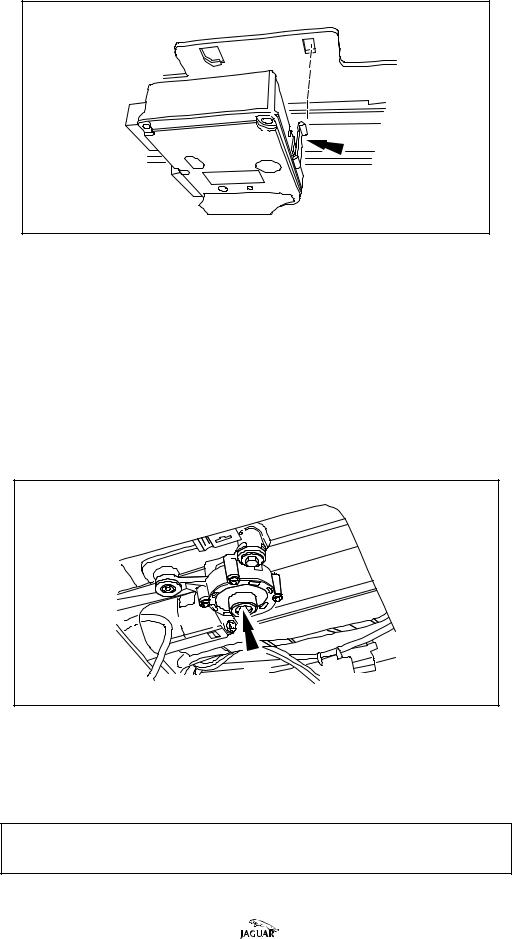
SRCM LOCATION
JSI-3477
ILLUSTRATION 3
•Intermittent operation can be caused by the Sliding Roof Control Module,
(SRCM), not being correctly located against the cables.
•The SRCM retaining tang (arrow) should be firmly engaged in the base plate, as indicated in Illustration 3, and secured by a tie-strap between the cables.
TILT AND SLIDE MECHANISM REMOVAL
•If the sliding roof has not fully closed, use a drive key or screwdriver in the slot in the gearbox shaft (indicated in Illustration 4) to rotate the shaft to manually close the sliding roof.
GEARBOX SHAFT
T.501.1170
ILLUSTRATION 4
•If the electrical drive and controls are verified as fault free, remove the sliding roof assembly, as detailed in JTIS 5, Section 501-17, SRO 76.82.01, to inspect the mechanical components.
Note: A replacement tilt and slide mechanism is available as a left or right side component.
Date of issue 11/98 |
Bulletin Number 13-39 Page 3 of 9 |
 Loading...