


 Loading...
O P E R A T I N G M A N U A L
Transpector® CPM
Compact Process Monitor
IPN 074-430-P1F

O P E R A T I N G M A N U A L
Transpector®CPM
Compact Process Monitor
IPN 074-430-P1F
®
www.inficon.com reachus@inficon.com
Due to our continuing program of product improvements, specifications are subject to change without notice.
©2007 INFICON
Trademarks
The trademarks of the products mentioned in this manual are held by the companies that produce them.
INFICON®, Transpector®, and FabGuard® are registered trademarks and FabGuard Explorer™ is a trademark of INFICON.
Windows®, Windows NT® and Microsoft® are registered trademarks of Microsoft Corporation.
Teflon® is a registered trademark of DuPont Co.
Swagelok® is a registered trademark of Swagelok Co.
All other brand and product names are trademarks or registered trademarks of their respective companies.
The information contained in this manual is believed to be accurate and reliable. However, INFICON assumes no responsibility for its use and shall not be liable for any special, incidental, or consequential damages related to the use of this product.
©2007 All rights reserved.
Reproduction or adaptation of any part of this document without permission is unlawful.

DECLARATION
OF
CONFORMITY
This is to certify that this equipment, designed and manufactured by:
INFICON Inc.
Two Technology Place
East Syracuse, NY 13057
USA
meets the essential safety requirements of the European Union and is placed on the market accordingly. It has been constructed in accordance with good engineeringpractice in safety matters in force in the Community and does not endanger the safety of persons, domestic animals or property when properly installed and maintained and used in applications for which it was made.
Equipment Description: |
CPM Pumping Packages including vacuum pumps and controllers. |
|
|
Transpector and sensor not included. |
|
|
This DOC only covers systems that include a Pfeiffer Vacuum turbopump. |
|
Applicable Directives: |
73/23/EEC as amended by 93/68/EEC |
|
|
89/336/EEC as amended by 93/68/EEC |
|
Applicable Standards: |
EN 61010-1:2001 |
|
|
EN 61326-1:A1:1998/A2:2001, Class A, Emissions per Table 3; |
|
|
Immunity per Table A.1 |
|
CE Implementation Date: |
September 2, 2005 |
|
Authorized Representative: |
Duane H. Wright |
|
|
Quality Assurance Manager, ISS |
|
|
INFICON |
Inc. |
ANY QUESTIONS RELATIVE TO THIS DECLARATION OR TO THE SAFETY OF INFICON'S PRODUCTS SHOULD BE DIRECTED, IN WRITING, TO THE QUALITY ASSURANCE DEPARTMENT AT THE ABOVE ADDRESS.
09/02/05

Warranty
WARRANTY AND LIABILITY - LIMITATION: Seller warrants the products manufactured by it, or by an affiliated company and sold by it, and described on the reverse hereof, to be, for the period of warranty coverage specified below, free from defects of materials or workmanship under normal proper use and service. The period of warranty coverage is specified for the respective products in the respective Seller instruction manuals for those products but shall not be less than one (1) year from the date of shipment thereof by Seller. Seller's liability under this warranty is limited to such of the above products or parts thereof as are returned, transportation prepaid, to Seller's plant, not later than thirty (30) days after the expiration of the period of warranty coverage in respect thereof and are found by Seller's examination to have failed to function properly because of defective workmanship or materials and not because of improper installation or misuse and is limited to, at Seller's election, either (a) repairing and returning the product or part thereof, or (b) furnishing a replacement product or part thereof, transportation prepaid by Seller in either case. In the event Buyer discovers or learns that a product does not conform to warranty, Buyer shall immediately notify Seller in writing of such non-conformity, specifying in reasonable detail the nature of such non-conformity. If Seller is not provided with such written notification, Seller shall not be liable for any further damages which could have been avoided if Seller had been provided with immediate written notification.
THIS WARRANTY IS MADE AND ACCEPTED IN LIEU OF ALL OTHER WARRANTIES, EXPRESS OR IMPLIED, WHETHER OF MERCHANTABILITY OR OF FITNESS FOR A PARTICULAR PURPOSE OR OTHERWISE, AS BUYER'S EXCLUSIVE REMEDY FOR ANY DEFECTS IN THE PRODUCTS TO BE SOLD HEREUNDER. All other obligations and liabilities of Seller, whether in contract or tort (including negligence) or otherwise, are expressly EXCLUDED. In no event shall Seller be liable for any costs, expenses or damages, whether direct or indirect, special, incidental, consequential, or other, on any claim of any defective product, in excess of the price paid by Buyer for the product plus return transportation charges prepaid.
No warranty is made by Seller of any Seller product which has been installed, used or operated contrary to Seller's written instruction manual or which has been subjected to misuse, negligence or accident or has been repaired or altered by anyone other than Seller or which has been used in a manner or for a purpose for which the Seller product was not designed nor against any defects due to plans or instructions supplied to Seller by or for Buyer.
This manual is intended for private use by INFICON® Inc. and its customers. Contact INFICON before reproducing its contents.
NOTE: These instructions do not provide for every contingency that may arise in connection with the installation, operation or maintenance of this equipment. Should you require further assistance, please contact INFICON.
www.inficon.com reachus@inficon.com

IPN 074-430-P1F
Transpector CPM Operating Manual
Table Of Contents
Chapter 1
Getting Started
1.1 General Safety Information. . . . . . . . . . . . . . . . . . . . . . . . . . . . . . . . . . . . . . 1-1 1.2 Introduction. . . . . . . . . . . . . . . . . . . . . . . . . . . . . . . . . . . . . . . . . . . . . . . . . . 1-2 1.2.1 Purpose of the CPM System . . . . . . . . . . . . . . . . . . . . . . . . . . . . . . . . . . . . 1-2 1.2.2 Description of the CPM System . . . . . . . . . . . . . . . . . . . . . . . . . . . . . . . . . . 1-2 1.3 Using this Manual . . . . . . . . . . . . . . . . . . . . . . . . . . . . . . . . . . . . . . . . . . . . . 1-3 1.3.1 Usage of the Modern Metric System . . . . . . . . . . . . . . . . . . . . . . . . . . . . . . 1-4 1.4 How To Contact Customer Support . . . . . . . . . . . . . . . . . . . . . . . . . . . . . . . 1-5 1.4.1 Returning Your Instrument to INFICON . . . . . . . . . . . . . . . . . . . . . . . . . . . . 1-5 1.5 CPM Performance Specifications. . . . . . . . . . . . . . . . . . . . . . . . . . . . . . . . . 1-6 1.5.1 General Specifications . . . . . . . . . . . . . . . . . . . . . . . . . . . . . . . . . . . . . . . . . 1-6 1.5.2 Hex Block Orifice Sampling Inlets . . . . . . . . . . . . . . . . . . . . . . . . . . . . . . . . 1-7 1.5.3 Atmospheric Pressure (Capillary) Sampling. . . . . . . . . . . . . . . . . . . . . . . . . 1-8 1.6 Physical Requirements. . . . . . . . . . . . . . . . . . . . . . . . . . . . . . . . . . . . . . . . . 1-9 1.6.1 Physical Dimensions . . . . . . . . . . . . . . . . . . . . . . . . . . . . . . . . . . . . . . . . . . 1-9 1.6.2 Weight . . . . . . . . . . . . . . . . . . . . . . . . . . . . . . . . . . . . . . . . . . . . . . . . . . . . 1-10 1.6.3 Ventilation Requirements . . . . . . . . . . . . . . . . . . . . . . . . . . . . . . . . . . . . . . 1-10 1.7 Electrical Power Requirements . . . . . . . . . . . . . . . . . . . . . . . . . . . . . . . . . 1-10 1.7.1 Required Supply Voltage . . . . . . . . . . . . . . . . . . . . . . . . . . . . . . . . . . . . . . 1-10 1.7.2 Acceptable Supply Voltage Range . . . . . . . . . . . . . . . . . . . . . . . . . . . . . . . 1-10 1.7.3 Required Frequency . . . . . . . . . . . . . . . . . . . . . . . . . . . . . . . . . . . . . . . . . . 1-10 1.7.4 Power Rating . . . . . . . . . . . . . . . . . . . . . . . . . . . . . . . . . . . . . . . . . . . . . . . 1-10 1.7.5 Fuse Rating . . . . . . . . . . . . . . . . . . . . . . . . . . . . . . . . . . . . . . . . . . . . . . . . 1-11 1.7.6 Overvoltage Category. . . . . . . . . . . . . . . . . . . . . . . . . . . . . . . . . . . . . . . . . 1-11 1.7.7 Electrical Connections . . . . . . . . . . . . . . . . . . . . . . . . . . . . . . . . . . . . . . . . 1-11 1.8 Nitrogen Purge Gas (Corrosive System Only) . . . . . . . . . . . . . . . . . . . . . . 1-11 1.9 Vent Gas Requirements for Two-Stage Foreline Pump . . . . . . . . . . . . . . . 1-12 1.10 Exhaust Gas . . . . . . . . . . . . . . . . . . . . . . . . . . . . . . . . . . . . . . . . . . . . . . . . 1-13 1.11 Air Pressure Requirements . . . . . . . . . . . . . . . . . . . . . . . . . . . . . . . . . . . . 1-13 1.11.1 Required Air Pressure . . . . . . . . . . . . . . . . . . . . . . . . . . . . . . . . . . . . . . . . 1-13 1.11.2 Acceptable Range of Air Pressure . . . . . . . . . . . . . . . . . . . . . . . . . . . . . . . 1-13 1.11.3 Moisture Content of Compressed Air Supply . . . . . . . . . . . . . . . . . . . . . . . 1-13 1.11.4 Air Pressure Connections. . . . . . . . . . . . . . . . . . . . . . . . . . . . . . . . . . . . . . 1-14 1.12 Vacuum Requirements . . . . . . . . . . . . . . . . . . . . . . . . . . . . . . . . . . . . . . . . 1-14 1.12.1 Required Vacuum. . . . . . . . . . . . . . . . . . . . . . . . . . . . . . . . . . . . . . . . . . . . 1-14 1.12.2 Acceptable Range Of Vacuum . . . . . . . . . . . . . . . . . . . . . . . . . . . . . . . . . . 1-14
TOC - 1

Transpector CPM Operating Manual
1.13 Environmental Requirements . . . . . . . . . . . . . . . . . . . . . . . . . . . . . . . . . . . 1-14
1.13.1 Use . . . . . . . . . . . . . . . . . . . . . . . . . . . . . . . . . . . . . . . . . . . . . . . . . . . . . . . 1-14
1.13.2 Altitude Range . . . . . . . . . . . . . . . . . . . . . . . . . . . . . . . . . . . . . . . . . . . . . . 1-14
1.13.3 Maximum Humidity. . . . . . . . . . . . . . . . . . . . . . . . . . . . . . . . . . . . . . . . . . . 1-14
1.13.4 Pollution Degree. . . . . . . . . . . . . . . . . . . . . . . . . . . . . . . . . . . . . . . . . . . . . 1-15
1.13.5 Maximum Operating Temperature . . . . . . . . . . . . . . . . . . . . . . . . . . . . . . . 1-15
1.13.6 Minimum Operating Temperatures. . . . . . . . . . . . . . . . . . . . . . . . . . . . . . . 1-15
1.13.7 Clean Room Requirements . . . . . . . . . . . . . . . . . . . . . . . . . . . . . . . . . . . . 1-15
1.13.8 Anti-Static Conditions . . . . . . . . . . . . . . . . . . . . . . . . . . . . . . . . . . . . . . . . . 1-15
1.14 Computer System Requirements . . . . . . . . . . . . . . . . . . . . . . . . . . . . . . . . 1-15
1.14.1 Operating System. . . . . . . . . . . . . . . . . . . . . . . . . . . . . . . . . . . . . . . . . . . . 1-16
1.15 Installation Overview . . . . . . . . . . . . . . . . . . . . . . . . . . . . . . . . . . . . . . . . . 1-16
1.16 Installing the CPM Sensor . . . . . . . . . . . . . . . . . . . . . . . . . . . . . . . . . . . . . 1-16
1.16.1 Sensor Installation . . . . . . . . . . . . . . . . . . . . . . . . . . . . . . . . . . . . . . . . . . . 1-17
1.16.1.1 ConFlat® Flanges . . . . . . . . . . . . . . . . . . . . . . . . . . . . . . . . . . . . . . . . . . . 1-17
1.16.1.1.1 Assembling ConFlat Flanges . . . . . . . . . . . . . . . . . . . . . . . . . . . . . . . . . . . 1-17
1.16.1.2 Attaching the sensor to the UHV Manifold Tee . . . . . . . . . . . . . . . . . . . . . 1-19
1.17 Sniffer Installation. . . . . . . . . . . . . . . . . . . . . . . . . . . . . . . . . . . . . . . . . . . . 1-20
1.18 Transpector2 Electronics Module Installation. . . . . . . . . . . . . . . . . . . . . . . 1-20
1.19How to Set the DIP Switches
on the Transpector2 . . . . . . . . . . . . . . . . . . . . . . . . . . . . . . . . . . . . . . . . . . 1-21 1.19.1 RS-232C Communications on the Transpector2 . . . . . . . . . . . . . . . . . . . . 1-22 1.19.2 RS-232C link . . . . . . . . . . . . . . . . . . . . . . . . . . . . . . . . . . . . . . . . . . . . . . . 1-22 1.19.2.1 Diagnostic link (SW8 - OFF). . . . . . . . . . . . . . . . . . . . . . . . . . . . . . . . . . . . 1-22 1.19.2.2 Primary link (SW8 - ON). . . . . . . . . . . . . . . . . . . . . . . . . . . . . . . . . . . . . . . 1-23 1.19.3 RS-485 Communications . . . . . . . . . . . . . . . . . . . . . . . . . . . . . . . . . . . . . . 1-23 1.19.3.1 RS-485 link (SW8 - OFF) . . . . . . . . . . . . . . . . . . . . . . . . . . . . . . . . . . . . . . 1-24 1.20 Mounting the Pumping System . . . . . . . . . . . . . . . . . . . . . . . . . . . . . . . . . 1-27 1.20.1 Installing the Support Kit . . . . . . . . . . . . . . . . . . . . . . . . . . . . . . . . . . . . . . 1-28 1.21 Installing the CPM Controller . . . . . . . . . . . . . . . . . . . . . . . . . . . . . . . . . . . 1-29 1.22 CPM Foreline Pump Installation. . . . . . . . . . . . . . . . . . . . . . . . . . . . . . . . . 1-31 1.23 Software Installation . . . . . . . . . . . . . . . . . . . . . . . . . . . . . . . . . . . . . . . . . . 1-33
Chapter 2
How the CPM System Works
2.1 CPM Components . . . . . . . . . . . . . . . . . . . . . . . . . . . . . . . . . . . . . . . . . . . . 2-1
2.2 Theory of Operation . . . . . . . . . . . . . . . . . . . . . . . . . . . . . . . . . . . . . . . . . . . 2-2
2.3 Instrument Overview . . . . . . . . . . . . . . . . . . . . . . . . . . . . . . . . . . . . . . . . . . 2-2
2.3.1 System Block Diagram . . . . . . . . . . . . . . . . . . . . . . . . . . . . . . . . . . . . . . . . . 2-2
2.3.2 CPM Aux I/O Connector. . . . . . . . . . . . . . . . . . . . . . . . . . . . . . . . . . . . . . . . 2-4
TOC - 2
IPN 074-430-P1F
IPN 074-430-P1F
Transpector CPM Operating Manual
2.3.2.1 Remote Control Functions . . . . . . . . . . . . . . . . . . . . . . . . . . . . . . . . . . . . . . 2-5
2.3.3 Ultra-High Vacuum System . . . . . . . . . . . . . . . . . . . . . . . . . . . . . . . . . . . . . 2-6
2.3.3.1 Foreline Subsystem . . . . . . . . . . . . . . . . . . . . . . . . . . . . . . . . . . . . . . . . . . . 2-6
2.3.4 Heater(s) Subsystem . . . . . . . . . . . . . . . . . . . . . . . . . . . . . . . . . . . . . . . . . . 2-7
2.3.5 CPM Controller Subsystem . . . . . . . . . . . . . . . . . . . . . . . . . . . . . . . . . . . . . 2-8
2.3.6 Solenoid Valves . . . . . . . . . . . . . . . . . . . . . . . . . . . . . . . . . . . . . . . . . . . . . . 2-9
2.3.7 Transpector Subsystem . . . . . . . . . . . . . . . . . . . . . . . . . . . . . . . . . . . . . . . 2-10
2.4 Application . . . . . . . . . . . . . . . . . . . . . . . . . . . . . . . . . . . . . . . . . . . . . . . . . 2-11
2.5 Sample Inlet Systems and Examples of Use . . . . . . . . . . . . . . . . . . . . . . . 2-12
2.5.1 Inlet System . . . . . . . . . . . . . . . . . . . . . . . . . . . . . . . . . . . . . . . . . . . . . . . . 2-12
2.5.2 High Pressure Sampling: Orifice Bypass (V4) . . . . . . . . . . . . . . . . . . . . . . 2-14
2.5.3 Dual-Capillary Sampling Option . . . . . . . . . . . . . . . . . . . . . . . . . . . . . . . . . 2-15
2.6 Advice and Tips . . . . . . . . . . . . . . . . . . . . . . . . . . . . . . . . . . . . . . . . . . . . . 2-16
2.6.1 Achieving Good Base Pressure in the CPM. . . . . . . . . . . . . . . . . . . . . . . . 2-16
2.6.2Avoiding Trapped Gas when
Sampling Valves are Closed . . . . . . . . . . . . . . . . . . . . . . . . . . . . . . . . . . . 2-16
Chapter 3
Theory and Application Guide
3.1 Theory of Operation . . . . . . . . . . . . . . . . . . . . . . . . . . . . . . . . . . . . . . . . . . . 3-1
3.2 Sensors . . . . . . . . . . . . . . . . . . . . . . . . . . . . . . . . . . . . . . . . . . . . . . . . . . . . 3-1
3.2.1 The Ion Source . . . . . . . . . . . . . . . . . . . . . . . . . . . . . . . . . . . . . . . . . . . . . . . 3-2
3.2.2 The Quadrupole Mass Filter . . . . . . . . . . . . . . . . . . . . . . . . . . . . . . . . . . . . . 3-4
3.2.2.1 Scanning Characteristics . . . . . . . . . . . . . . . . . . . . . . . . . . . . . . . . . . . . . . . 3-6
3.2.2.2 The Zero Blast . . . . . . . . . . . . . . . . . . . . . . . . . . . . . . . . . . . . . . . . . . . . . . . 3-7
3.2.3 The Ion Detector. . . . . . . . . . . . . . . . . . . . . . . . . . . . . . . . . . . . . . . . . . . . . . 3-8
3.2.3.1 The Electron Multiplier (EM) Detector . . . . . . . . . . . . . . . . . . . . . . . . . . . . . 3-8
3.3 How to Interpret The Result . . . . . . . . . . . . . . . . . . . . . . . . . . . . . . . . . . . . . 3-9
3.3.1 Qualitative Interpretation Of Mass Spectra. . . . . . . . . . . . . . . . . . . . . . . . . . 3-9
3.3.1.1 Ionization Process . . . . . . . . . . . . . . . . . . . . . . . . . . . . . . . . . . . . . . . . . . . 3-11
3.3.1.2 Isotope Ratios. . . . . . . . . . . . . . . . . . . . . . . . . . . . . . . . . . . . . . . . . . . . . . . 3-13
3.3.1.3 Electron Energy Effects . . . . . . . . . . . . . . . . . . . . . . . . . . . . . . . . . . . . . . . 3-15
3.3.1.4 A Qualitative Interpretation Guide . . . . . . . . . . . . . . . . . . . . . . . . . . . . . . . 3-17
3.3.1.5 Dry Etching Chemistries . . . . . . . . . . . . . . . . . . . . . . . . . . . . . . . . . . . . . . . 3-20
3.3.1.6 Tungsten CVD . . . . . . . . . . . . . . . . . . . . . . . . . . . . . . . . . . . . . . . . . . . . . . 3-23
3.3.1.7 Copper MOCVD . . . . . . . . . . . . . . . . . . . . . . . . . . . . . . . . . . . . . . . . . . . . . 3-23
3.3.2Quantitative Interpretation of Mass Spectra
(Calculating Partial Pressures) . . . . . . . . . . . . . . . . . . . . . . . . . . . . . . . . . . 3-24
3.3.3Additional Information For
Interpreting Mass Spectra . . . . . . . . . . . . . . . . . . . . . . . . . . . . . . . . . . . . . 3-30
TOC - 3

Transpector CPM Operating Manual
3.3.3.1 Ion Source Characteristics . . . . . . . . . . . . . . . . . . . . . . . . . . . . . . . . . . . . . 3-30
3.3.3.2 Scanning Characteristics . . . . . . . . . . . . . . . . . . . . . . . . . . . . . . . . . . . . . . 3-32
3.3.3.3 Fragmentation Factors . . . . . . . . . . . . . . . . . . . . . . . . . . . . . . . . . . . . . . . . 3-32
Chapter 4
Operation
4.1 CPM Controller Front Panel . . . . . . . . . . . . . . . . . . . . . . . . . . . . . . . . . . . . . 4-1
4.1.1 LED Indicators . . . . . . . . . . . . . . . . . . . . . . . . . . . . . . . . . . . . . . . . . . . . . . . 4-1
4.2 HexBlock . . . . . . . . . . . . . . . . . . . . . . . . . . . . . . . . . . . . . . . . . . . . . . . . . . . 4-3
4.2.1 HexBlock Inlet . . . . . . . . . . . . . . . . . . . . . . . . . . . . . . . . . . . . . . . . . . . . . . . 4-3
4.2.1.1 Hex Block Process Connections . . . . . . . . . . . . . . . . . . . . . . . . . . . . . . . . . 4-5
4.2.2 Calibration Option. . . . . . . . . . . . . . . . . . . . . . . . . . . . . . . . . . . . . . . . . . . . . 4-5
4.2.3 Process Gauge (CDG) . . . . . . . . . . . . . . . . . . . . . . . . . . . . . . . . . . . . . . . . . 4-6
4.3 Heaters. . . . . . . . . . . . . . . . . . . . . . . . . . . . . . . . . . . . . . . . . . . . . . . . . . . . . 4-7
4.4 Pumping System . . . . . . . . . . . . . . . . . . . . . . . . . . . . . . . . . . . . . . . . . . . . . 4-7
4.4.1 Foreline Pump . . . . . . . . . . . . . . . . . . . . . . . . . . . . . . . . . . . . . . . . . . . . . . . 4-7
4.4.2 Turbo Molecular Pump . . . . . . . . . . . . . . . . . . . . . . . . . . . . . . . . . . . . . . . . . 4-8
4.4.2.1 Turbo Molecular Pump Status . . . . . . . . . . . . . . . . . . . . . . . . . . . . . . . . . . . 4-9
4.5Nitrogen Purge Valve for the Turbo Molecular Pump
on Corrosive Pumping Systems . . . . . . . . . . . . . . . . . . . . . . . . . . . . . . . . . . 4-9 4.6 Foreline Vent Valve . . . . . . . . . . . . . . . . . . . . . . . . . . . . . . . . . . . . . . . . . . . 4-9 4.7 Filament Control . . . . . . . . . . . . . . . . . . . . . . . . . . . . . . . . . . . . . . . . . . . . . 4-10 4.7.1 Interlock . . . . . . . . . . . . . . . . . . . . . . . . . . . . . . . . . . . . . . . . . . . . . . . . . . . 4-10 4.7.2 Total Pressure Calibration . . . . . . . . . . . . . . . . . . . . . . . . . . . . . . . . . . . . . 4-10 4.7.3 Filament Lifetime . . . . . . . . . . . . . . . . . . . . . . . . . . . . . . . . . . . . . . . . . . . . 4-11 4.8 Pneumatic Digital Pressure Switch and Pressure Gauge . . . . . . . . . . . . . 4-14 4.8.1 Setup Procedure . . . . . . . . . . . . . . . . . . . . . . . . . . . . . . . . . . . . . . . . . . . . 4-14 4.8.2 How to Test for Proper Settings . . . . . . . . . . . . . . . . . . . . . . . . . . . . . . . . . 4-16 4.8.3 How to Lock and Unlock the Settings. . . . . . . . . . . . . . . . . . . . . . . . . . . . . 4-16
Chapter 5
Maintenance
5.1 Introduction. . . . . . . . . . . . . . . . . . . . . . . . . . . . . . . . . . . . . . . . . . . . . . . . . . 5-1
5.2 Safety Considerations . . . . . . . . . . . . . . . . . . . . . . . . . . . . . . . . . . . . . . . . . 5-1
5.2.1 Toxic Material . . . . . . . . . . . . . . . . . . . . . . . . . . . . . . . . . . . . . . . . . . . . . . . . 5-2
5.2.2 Radiation . . . . . . . . . . . . . . . . . . . . . . . . . . . . . . . . . . . . . . . . . . . . . . . . . . . 5-2
5.2.3 Electrical Voltages . . . . . . . . . . . . . . . . . . . . . . . . . . . . . . . . . . . . . . . . . . . . 5-2
5.3Required Environment, Tools,
Materials, or Parts . . . . . . . . . . . . . . . . . . . . . . . . . . . . . . . . . . . . . . . . . . . . 5-3 5.3.1 Environment . . . . . . . . . . . . . . . . . . . . . . . . . . . . . . . . . . . . . . . . . . . . . . . . . 5-3 5.3.2 Tools Required for Maintenance . . . . . . . . . . . . . . . . . . . . . . . . . . . . . . . . . 5-3
TOC - 4
IPN 074-430-P1F

IPN 074-430-P1F
Transpector CPM Operating Manual
5.3.3 Parts Required For Maintenance . . . . . . . . . . . . . . . . . . . . . . . . . . . . . . . . . 5-3 5.4 Changing Diaphragms in the Foreline Pump . . . . . . . . . . . . . . . . . . . . . . . . 5-4 5.5 Transpector Sensor Maintenance . . . . . . . . . . . . . . . . . . . . . . . . . . . . . . . 5-11
5.5.1How to Determine if a Filament
Replacement is Required . . . . . . . . . . . . . . . . . . . . . . . . . . . . . . . . . . . . . . 5-11 5.5.2 Transpector Filament Replacement . . . . . . . . . . . . . . . . . . . . . . . . . . . . . . 5-12 5.5.3 Transpector Sensor Ion Source Replacement . . . . . . . . . . . . . . . . . . . . . . 5-14 5.5.4 Transpector Sensor Electron Multiplier Replacement . . . . . . . . . . . . . . . . 5-17 5.6 HexBlock Inlet Maintenance . . . . . . . . . . . . . . . . . . . . . . . . . . . . . . . . . . . . 5-18 5.6.1 Valve and Orifice Replacement . . . . . . . . . . . . . . . . . . . . . . . . . . . . . . . . . 5-18
Chapter 6
Diagnosing Problems
6.1 Introduction. . . . . . . . . . . . . . . . . . . . . . . . . . . . . . . . . . . . . . . . . . . . . . . . . . 6-1
6.2 CPM Symptom - Cause - Remedy Chart . . . . . . . . . . . . . . . . . . . . . . . . . . . 6-1
6.3 If You Cannot Resolve Your Problem. . . . . . . . . . . . . . . . . . . . . . . . . . . . . . 6-2
6.4 Event Log Files. . . . . . . . . . . . . . . . . . . . . . . . . . . . . . . . . . . . . . . . . . . . . . . 6-2
Chapter 7
Recommended Parts List
7.1 CPM Consumable Parts . . . . . . . . . . . . . . . . . . . . . . . . . . . . . . . . . . . . . . . . 7-1
7.2 Preventative Maintenance Parts. . . . . . . . . . . . . . . . . . . . . . . . . . . . . . . . . . 7-2
7.3 Replacement Spare Parts . . . . . . . . . . . . . . . . . . . . . . . . . . . . . . . . . . . . . . 7-2
Chapter 8
FabGuard Explorer Operation
8.1 Operation (FabGuard Explorer) . . . . . . . . . . . . . . . . . . . . . . . . . . . . . . . . . . 8-1
8.2 Introduction. . . . . . . . . . . . . . . . . . . . . . . . . . . . . . . . . . . . . . . . . . . . . . . . . . 8-1
8.3 Hardware Configuration . . . . . . . . . . . . . . . . . . . . . . . . . . . . . . . . . . . . . . . . 8-2
8.4 RGA Configuration - CPM Tab . . . . . . . . . . . . . . . . . . . . . . . . . . . . . . . . . . . 8-4
8.4.1 Valves and Orifices. . . . . . . . . . . . . . . . . . . . . . . . . . . . . . . . . . . . . . . . . . . . 8-5
8.4.2 Gauges . . . . . . . . . . . . . . . . . . . . . . . . . . . . . . . . . . . . . . . . . . . . . . . . . . . . . 8-7
8.4.3 Pumping Timers . . . . . . . . . . . . . . . . . . . . . . . . . . . . . . . . . . . . . . . . . . . . . . 8-8
8.5 CPM Configuration Monitor . . . . . . . . . . . . . . . . . . . . . . . . . . . . . . . . . . . . . 8-9
8.6 CPM Acquisition Control. . . . . . . . . . . . . . . . . . . . . . . . . . . . . . . . . . . . . . . 8-13
8.6.1 Acquisition Modes . . . . . . . . . . . . . . . . . . . . . . . . . . . . . . . . . . . . . . . . . . . 8-13
8.6.2 Scan Settings . . . . . . . . . . . . . . . . . . . . . . . . . . . . . . . . . . . . . . . . . . . . . . . 8-14
8.6.3 Function . . . . . . . . . . . . . . . . . . . . . . . . . . . . . . . . . . . . . . . . . . . . . . . . . . . 8-14
8.6.4 Ionizer Presets . . . . . . . . . . . . . . . . . . . . . . . . . . . . . . . . . . . . . . . . . . . . . . 8-15
8.6.5 Start Mode . . . . . . . . . . . . . . . . . . . . . . . . . . . . . . . . . . . . . . . . . . . . . . . . . 8-15
8.6.5.1 Start Mode Type . . . . . . . . . . . . . . . . . . . . . . . . . . . . . . . . . . . . . . . . . . . . . 8-15
TOC - 5

Transpector CPM Operating Manual
8.6.5.2 Data Threshold. . . . . . . . . . . . . . . . . . . . . . . . . . . . . . . . . . . . . . . . . . . . . . 8-16
8.6.5.3 Emission and Multiplier . . . . . . . . . . . . . . . . . . . . . . . . . . . . . . . . . . . . . . . 8-16
8.6.6 Stop Mode . . . . . . . . . . . . . . . . . . . . . . . . . . . . . . . . . . . . . . . . . . . . . . . . . 8-17
8.6.6.1 Stop Mode Type . . . . . . . . . . . . . . . . . . . . . . . . . . . . . . . . . . . . . . . . . . . . . 8-17
8.6.6.2 Data Threshold. . . . . . . . . . . . . . . . . . . . . . . . . . . . . . . . . . . . . . . . . . . . . . 8-17
8.6.6.3 Maximum Step Duration. . . . . . . . . . . . . . . . . . . . . . . . . . . . . . . . . . . . . . . 8-18
8.6.6.4 Emission and Multiplier . . . . . . . . . . . . . . . . . . . . . . . . . . . . . . . . . . . . . . . 8-18
8.6.7 Stabilization Time . . . . . . . . . . . . . . . . . . . . . . . . . . . . . . . . . . . . . . . . . . . . 8-18
8.6.8 Dwell. . . . . . . . . . . . . . . . . . . . . . . . . . . . . . . . . . . . . . . . . . . . . . . . . . . . . . 8-19
8.6.9 Delay Time . . . . . . . . . . . . . . . . . . . . . . . . . . . . . . . . . . . . . . . . . . . . . . . . . 8-19
8.6.10 Baseline and Peak Lock. . . . . . . . . . . . . . . . . . . . . . . . . . . . . . . . . . . . . . . 8-20
8.6.10.1 Baseline . . . . . . . . . . . . . . . . . . . . . . . . . . . . . . . . . . . . . . . . . . . . . . . . . . . 8-20
8.6.10.2 Peak Lock. . . . . . . . . . . . . . . . . . . . . . . . . . . . . . . . . . . . . . . . . . . . . . . . . . 8-20
8.6.11 Inlet. . . . . . . . . . . . . . . . . . . . . . . . . . . . . . . . . . . . . . . . . . . . . . . . . . . . . . . 8-21
8.6.11.1 Inlet Type . . . . . . . . . . . . . . . . . . . . . . . . . . . . . . . . . . . . . . . . . . . . . . . . . . 8-21
Chapter 9
Glossary
Chapter 10
Bibliography
Index
IPN 074-430-P1F
TOC - 6

Transpector CPM Operating Manual
Chapter 1
Getting Started
1.1 General Safety Information
WARNING
This product is not for use in a manner not specified by the manufacturer.
WARNING - Risk Of Electric Shock
There are no user serviceable components within the instrument case.
WARNING - Risk Of Electric Shock
Potentially lethal voltages are present when the line cord is connected.
WARNING - Risk Of Electric Shock
Refer all maintenance to qualified personnel.
IPN 074-430-P1F
1 - 1

Transpector CPM Operating Manual
1.2 Introduction
This manual provides information regarding the operation of the INFICON® CPM Gas Analysis System. This chapter provides an overview of the CPM system.
1.2.1 Purpose of the CPM System
The CPM system is designed to sample a representative fraction of a process environment and direct the gas sample to the ionization region of a Residual Gas Analyzer (RGA). The CPM has a dry pumping package that is small, light weight, and portable. The CPM can detect levels of impurities in process gases at sub-ppm levels for many components.
1.2.2 Description of the CPM System
The CPM system is comprised of:
FabGuard® or FabGuard Explorer™ software, works with the CPM system to provide automatic or manual control as well as status information. The software provides automatic valve control through recipes and manual control of all components. It includes a full array of basic residual gas analyzer (RGA) features, including Spectrum or Selected Peaks scanning, Leak Detection and Recipe Generation.
Quadrupole Sensor, analyzes gases by: (1) ionizing the gas molecules, (2) separating the ions by their mass-to-charge ratio, and (3) measuring the quantity of ions at each mass. The sensor can indicate the partial pressures of gases characteristic of processes occurring within a vacuum or other vessel, and therefore can be used to investigate the nature of a process or to monitor process conditions.
Electronics Module (Transpector® 2), controls the sensor. The electronics module and sensor are a matched set. The electronics module attaches to and is supported by the sensor.
CPM Controller, consolidates control functions into a single device that is self standing or rack mountable. The CPM controller works in conjunction with the Transpector2 to control valve activation, heaters, pumps, and power to all elements of the system.
Pumping System, is small, light weight, and efficient and can handle lighter gases allowing process sampling from two atmospheres to high vacuum.
Inlet Valves, a HexBlock™ inlet that can provide several sampling ranges, a calibration reference, and a process pressure gauge.
IPN 074-430-P1F
1 - 2
Transpector CPM Operating Manual
1.3 Using this Manual
NOTE: Notes provide additional information about the current topic.
HINT: Hints provide insight into product usage.
CAUTION
CAUTION paragraphs caution against actions which may bring about a malfunction or the loss of data.
WARNING
WARNING paragraphs warn against actions that may result in personal injury.
WARNING - Risk Of Electric Shock
ELECTRICAL WARNING paragraphs warn of the presence of potentially lethal voltages.
IPN 074-430-P1F
1 - 3

Transpector CPM Operating Manual
1.3.1 Usage of the Modern Metric System
In many places throughout this manual, American measurement units are given along with their International System of Units eqivalences. However, providing all measurement units in all discussions becomes cumbersome to the reader. Therefore, equivalences are not given in all cases. You may perform the conversion as follows:
To convert from PSIG to bar PSIG x 0.069 = bar
To convert from PSIG to kPa PSIG x 6.8947 = kPa
To convert from Torr to mbar Torr x 1.3332 = mbar
To convert from Torr to Pascals (Pa) Torr x 133.32 = Pa
To convert from inches (in.) to millimeter (mm) in. x 25.4 = mm
To convert from feet (ft.) to meters (m) ft. x 0.3048 = m
When converting from pounds (lb.) to kilograms (kg) lb. x 0.453593 = kg
IPN 074-430-P1F
1 - 4

IPN 074-430-P1F
Transpector CPM Operating Manual
1.4 How To Contact Customer Support
Worldwide support information regarding:
Technical Support, to contact an applications engineer with questions regarding INFICON products and applications, or
Sales and Customer Service, to contact the INFICON Sales office nearest you, or
Repair Service, to contact the INFICON Service Center nearest you,
is available at www.inficon.com.
If you are experiencing a problem with your instrument, please have the following information readily available:
the serial number for your instrument,
a description of your problem,
an explanation of any corrective action that you may have already attempted,
and the exact wording of any error messages that you may have received. To contact Customer Support, see Support at www.inficon.com.
1.4.1Returning Your Instrument to INFICON
Do not return any component of your instrument to INFICON without first speaking with a Customer Support Representative. You must obtain a Return Material Authorization (RMA) number from the Customer Support Representative.
If you deliver a package to INFICON without an RMA number, your package will be held and you will be contacted. This will result in delays in servicing your instrument.
Prior to being given an RMA number, you will be required to complete a Declaration Of Contamination (DOC) form if your instrument has been exposed to process materials. DOC forms must be approved by INFICON before an RMA number is issued. INFICON may require that the instrument be sent to a designated decontamination facility, not to the factory.
1 - 5

Transpector CPM Operating Manual
1.5 CPM Performance Specifications
1.5.1 General Specifications
Table 1-1 General Specifications
Mass Range (AMU) |
1 - 100 |
1 - 200 |
1 - 300 |
|
|
|
|
|
|
|
|
Resolution |
<1 AMU wide @ 10% peak height over entire mass range |
|
|||
|
|
(per AVS 1993 recommended practice) |
|
||
|
|
|
|
||
Total Pressure Range1 |
5x10⁻⁷ - 1x10⁻³ Torr (6.6x10⁻⁷ - 1.3x10⁻³ mbar) |
|
|
||
Total Pressure Accuracy2 |
+/-25% 1x10⁻⁶ - 1x10⁻³ Torr (1.3x10⁻⁶ - 1.3x10⁻³ mbar) |
|
|||
Maximum Ion Source |
1x10⁻³ Torr (1.3x10⁻³ mbar) |
|
|
||
Operating Pressure3 |
|
|
|
|
|
Nominal Operating |
2x10⁻⁴ Torr (2.6x10⁻⁴ mbar) |
|
|
||
Pressure4 |
|
|
|
|
|
System Operating |
1x10⁻⁸ Torr (1.3x10⁻⁸ mbar) - 2 atmospheres (with proper inlet configuration) |
|
|||
Pressure |
|
|
|
|
|
|
|
|
|
|
|
Multiplier Gain5 |
> 10,000 (@ 1225 Volts) |
|
|
|
|
Sensitivity |
Amps/Torr (Amps/mbar) |
Amps/Torr (Amps/mbar) |
Amps/Torr (Amps/mbar) |
|
|
|
@ Low Emission |
>4x10⁻⁶ (>3x10⁻⁶) |
>2x10⁻⁶ (>1.5x10⁻⁶) |
> 1x10⁻⁶ (>7.6x10⁻⁷) |
|
|
@ High Emission |
>2x10⁻⁵ (>1.5x10⁻⁵) |
>1x10⁻⁵ (>7.6x10⁻⁶) |
> 5x10⁻⁶ (>3.8x10⁻⁶) |
|
Minimal Detectable |
1x10-13 Torr |
2x10-13 Torr |
4x10-13 Torr |
|
|
Partial Pressure6 |
(1.3x10⁻¹³ mbar) |
(2.6x10⁻¹³ mbar) |
(5.3x10⁻¹³ mbar) |
|
|
Abundance Sensitivity7 |
< 5 ppm |
< 10 ppm |
< 100 ppm |
|
|
Zero Blast8 |
< 2 ppm |
< 25 ppm |
< 200 ppm |
|
|
Detection Limit9 |
< 1 ppm |
< 2 ppm |
< 4 ppm |
|
|
Linearity10 |
+/- 20% |
|
|
430-P1F |
|
Minimum Background |
1x10⁻⁸Torr |
|
|
||
Pressure |
(1.3x10⁻⁸ mbar) |
|
|
074- |
|
|
|
|
|
|
IPN |
Maximum Sensor and |
150°C |
|
|
||
|
|
|
|||
Inlet Temperature |
|
|
|
|
|
|
|
|
|
|
|
1 |
Ion source pressure reading @ low emission using total pressure lens |
|
|
||
2 |
Total pressure accuracy @ low emission |
|
|
|
|
3 |
Maximum ion source operating pressure @ low emission |
|
|
||
4 |
2x10⁻⁴ Torr in the ion source will produce about 1x10⁻⁵ Torr in the quadrupole region |
|
|||
5 |
Minimum EM gain at maximum EM voltage |
|
|
|
|
6 |
MDPP with EM on and 1 second dwell time |
|
|
|
|
7 |
Mass 40 contribution onto 41 AMU |
|
|
|
|
8 |
Zero blast contribution onto 2 AMU |
|
|
|
|
9 |
Minimal detectable concentration with Krypton in air @ a 1 second dwell time |
|
|
||
10 Linearity @ low emission at 0.1 to 2 times the nominal orifice pressure |
|
|
|||
1 - 6
IPN 074-430-P1F
Transpector CPM Operating Manual
1.5.2 Hex Block Orifice Sampling Inlets
Table 1-2 HexBlock Inlets and available Orifices (Maximum nominal pressure for orifice)
Inlet |
Orifices |
|
|
V1 (LP) |
3mT (no orifice) |
|
10mT |
|
15mT |
|
100mT |
|
360mT |
|
1T |
|
|
V2 (HP) |
3mT (no orifice) |
|
10mT |
|
15mT |
|
100mT |
|
360mT |
|
1T(bypass) |
|
3T (bypass) |
|
10T (bypass) |
|
30T(bypass) |
|
1T Sniffer (bypass) |
|
3T Sniffer (bypass) |
|
7T Sniffer (bypass) |
|
10T Sniffer (bypass |
|
30T Sniffer (bypass) |
|
100T Sniffer (bypass) |
|
|
V3 (HC) |
1mT (High Conductance) |
|
|
1 - 7

Transpector CPM Operating Manual
1.5.3 Atmospheric Pressure (Capillary) Sampling
Table 1-3 Capillary Sampling Option
Process Pressure Range |
300 to 1400 Torr (400 to 1867 mbar) |
|
|
Capillary Size and Lengths |
1/16" O.D. x 1.5 m SS capillary |
|
1/16" O.D. x 3.0 m SS capillary |
|
|
Process Gas Consumption |
2 sccm @ 300 Torr (400 mbar) |
|
10 sccm @ 760 Torr (1013 mbar) |
|
30 sccm @ 1400 Torr (1867 mbar) |
|
|
Response Time for Composition Changes |
Capillary Delay: t(1.5m) = 0.3 s |
(response to normal inert gases) |
t(3.0m) = 1 s |
|
Intermediate Volume Tau = 0.7 s |
|
CPM Isolation time constant = 75 s |
|
|
IPN 074-430-P1F
1 - 8

IPN 074-430-P1F
Transpector CPM Operating Manual
1.6 Physical Requirements
1.6.1 Physical Dimensions
Figure 1-1 Pumping System Dimensions
|
18.6 in. |
|
472 mm |
|
3.0 in. |
|
76 mm |
|
6.0 in. |
|
152 mm |
|
14.8 in. |
|
376 mm |
11.4 in. |
7.2 in. |
290 mm |
183 mm |
Pumping System dimensions
18.6 in x 6.0 in x 14.8 in (472 mm x 152 mm x 376 mm)
CPM Controller dimensions
3.5 in x 6 in x 12 in (89 mm x 152 mm x 305 mm)
Foreline Pump dimensions
4.1 in x 7.1 in x 4.6 in (104 mm x 180 mm x 116 mm) (See Figure 2-4 in section section 2.3.3.1 for connections):
1 - 9

Transpector CPM Operating Manual
1.6.2 Weight
The weight of the CPM system (without the Foreline Pump and the CPM controller) is 32 lb (14.5 kg).
NOTE: These weights do not include connecting cables.
1.6.3 Ventilation Requirements
CAUTION
For adequate ventilation, maintain at least 1 in. (25.4 mm) clearance around the Transpector2 electronics module and the CPM heaters and pumping system.
If the CPM pumping system and/or the CPM controller is inside an enclosure, the enclosure must be large or ventilated to provide adequate cooling by the fan on the CPM pumping system and the fan in the CPM controller.
1.7 Electrical Power Requirements
The CPM system components that require AC power input are:
CPM controller . . . . . . . . . . . . . . . . . Universal input, any voltage in the range specified in section 1.7.2 is acceptable.
Personal computer . . . . . . . . . . . . . . Universal input, any voltage in the range specified in section 1.7.2 is acceptable.
1.7.1 Required Supply Voltage
Except for the AC power input requirements, all other required supply voltages are supplied by the CPM controller.
1.7.2 Acceptable Supply Voltage Range
AC Power requirements are 100, 120, or 230 V(ac), ±10%
NOTE: If the input power is less than 100 V(ac), the time required for the heaters to reach their nominal temperature may be extended.
1.7.3 Required Frequency
50 or 60 Hz, ±5%
1.7.4 Power Rating
CPM controller . . . . . . . . . . . . . . . . . 500 VA
1 - 10
IPN 074-430-P1F

IPN 074-430-P1F
Transpector CPM Operating Manual
1.7.5Fuse Rating
3.15A @ 250 V(ac) T (5 x 20 mm)
1.7.6Overvoltage Category
Overvoltage Category II (per EN61010-1:2001)
1.7.7 Electrical Connections
110 V(ac), three-pronged, grounded plug. Or,
230V(ac), European style, two-pronged plug with ground contact.
1.8Nitrogen Purge Gas (Corrosive System Only)
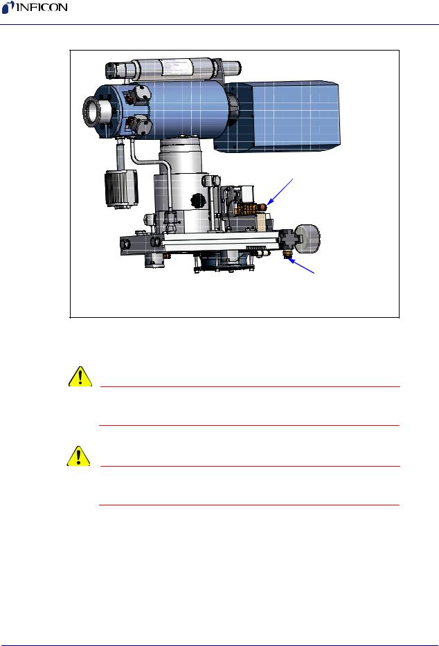
The corrosive service Turbo Molecular Pump requires 10 to 25 sccm of purge gas flow through the bearing region to protect the bearings from corrosion and loss of bearing lubricant by evaporation. Dry nitrogen is recommended as the purge gas. The CPM has a regulator that is preset in the factory using a flow meter to produce 10 sccm of nitrogen purge. To produce 10 sccm, the nitrogen regulator should be set between 10 and 15 PSIG.
CAUTION
For the corrosive service Turbo Molecular Pump (CVD/Etch), the nitrogen purge gas is required at all times the system is operational.
Normally, dry nitrogen is supplied at the acceptable pressure range for the Air Pressure, section 1.11.1 on page 1-13. In this manner, dry nitrogen can be supplied directly to the solenoid valve block and to the pressure regulator via the supplied 1/4" (6.35 mm) tee. The provided regulator will then supply dry nitrogen at a reduced pressure for the purge.
1 - 11
Transpector CPM Operating Manual
Figure 1-2 Compressed Air Supply Connection
Dry Compressed Air |
58 - 100 PSIG |
Dry Nitrogen |
20 - 125 PSIG |
Bearing Purge |
Corrosive System Only |
The acceptable range of pressure is 58 PSIG to 100 PSIG (4 to 6.9 bar) [400 kPa to 690 kPa].
WARNING
The nitrogen pressure must not exceed 100 PSIG (6.9 bar) [690 kPa].
CAUTION
The nitrogen pressure must be at least 58 PSIG (4 bar) [400 kPa].
1.9 Vent Gas Requirements for Two-Stage Foreline Pump
Venting with dry Nitrogen is not required unless sampling Hydrogen, although it is recommended when sampling reactive gases to minimize reactions with surface areas. Dry Nitrogen should be used for venting with a supply of < 2 PSIG. Simple 1/4" (6.35 mm) plastic tubing can be connected to dry Foreline Pump for venting.
NOTE: The four-stage Foreline Pump does not utilize a vent valve.
1 - 12
IPN 074-430-P1F
IPN 074-430-P1F
Transpector CPM Operating Manual
1.10 Exhaust Gas
For corrosive applications, exhausting the Turbo Molecular Pump is required. For non-corrosive applications, exhausting of the Turbo Molecular Pump can be done in accordance to the facility's requirements. The dry Foreline Pump has a 1/4" (6.35
mm)Swagelok® tube adapter for an exhaust fitting.
1.11Air Pressure Requirements
The CPM air pressure requirements are discussed in the following sections. Refer to Figure 1-2 for compressed air supply connection.
1.11.1 Required Air Pressure
Dry compressed air (or dry nitrogen) is used to operate the electro-pneumatic inlet valves. The minimum air pressure required to operate the inlet valves is 58 PSIG (4 bar) [400 kPa].
1.11.2 Acceptable Range of Air Pressure
The acceptable range of air pressure is 58 PSIG to 100 PSIG (4 to 6.9 bar) [400 kPa to 690 kPa].
WARNING
The air pressure must not exceed 100 PSIG (6.9 bar) [690 kPa].
CAUTION
The air pressure must be at least 58 PSIG (4 bar) [400 kPa].
1.11.3 Moisture Content of Compressed Air Supply
The compressed air supply used for inlet valve operation should be dried to the extent that changes in pressure of the compressed air during operation does not produce condensation in lines, solenoids or valve actuators. Moisture condensation can cause corrosion.
1 - 13

Transpector CPM Operating Manual
1.11.4 Air Pressure Connections
The compressed air supply connects to the CPM solenoid with 1/4 in.
(6.35 mm) polymer hose. The 1/4 in. (6.35 mm) connector is a friction lock right angle fitting to adapt the supply hose to the 10-32 threads of the solenoid base.
1.12 Vacuum Requirements
The CPM vacuum requirements are as follows.
1.12.1 Required Vacuum
The CPM System creates vacuum with the Turbo Molecular Pump and Foreline Pump. If you provide the Foreline Pump, it must provide < 10 Torr (13 mbar) when there is up to 30 sccm of N2 purge plus process gas bypass flow.
CAUTION
If the Foreline Pump pressure exceeds 10 Torr (13 mbar), degradation of the data and the CPM system is possible.
1.12.2 Acceptable Range Of Vacuum
The CPM manifold can achieve < 1x10⁻⁸ Torr (1.33x10⁻⁸ mbar) of base pressure (no sample flow) after bakeout and cool down. Achieving this level of vacuum requires a foreline pressure of < 10 Torr (13 mbar).
1.13 Environmental Requirements
The CPM Environmental requirements are discussed in the following sections.
1.13.1 Use
The CPM is intended for indoor use only.
1.13.2 Altitude Range
The CPM can be used up to a maximum altitude of 6561 ft (2000) m. For operation at higher altitudes, please consult the factory.
1.13.3 Maximum Humidity
80% relative humidity (no condensation).
1 - 14
IPN 074-430-P1F

IPN 074-430-P1F
Transpector CPM Operating Manual
1.13.4 Pollution Degree
Pollution Degree 2 (per EN61010-1:2001)
1.13.5 Maximum Operating Temperature
104°F (40°C) (electronics module)
1.13.6 Minimum Operating Temperatures
68°F (20°C)
1.13.7 Clean Room Requirements
The CPM system construction is clean room compatible (including silicone rubber heaters).
1.13.8 Anti-Static Conditions
The CPM unit has been tested for static susceptibility and passes standard EN 61326-1:2000.
1.14 Computer System Requirements
INFICON can supply a complete computer system for operation of the Transpector software that will operate the Transpector Gas Analysis instrument connected to a CPM System.
The minimum system requirements for FabGuard Explorer Operating Software are listed in Table 1-4:
Table 1-4 Minimum Computer Requirements for FabGuard Explorer
Parameters |
FabGuard Explorer |
|
Requirements |
|
|
Processor |
Pentium 4 2.0 GHz or greater |
|
|
Memory |
512 MB or greater |
|
|
Hard Drive |
500 MB for program, |
|
additional space needed for |
|
data collection |
Resolution |
800 x 600 16-Bit color or |
|
greater |
Cable Required |
RS-232C Cable (for single |
|
sensor operation) or RS-485 |
|
cable for multiple sensor |
|
operation (both cables are |
|
included with the CPM) |
|
|
1 - 15

Transpector CPM Operating Manual
The minimum system requirements for FabGuard Sensor Integration and Analysis Software are listed in Table 1-5:
Table 1-5 Minimum Computer Requirements for FabGuard
|
Minimum Requirement |
|
|
Processor |
Dual Xeon, 2.0 GHz |
|
|
Memory |
512 MB |
|
|
Hard Drive |
36 GB |
|
|
Resolution |
17" (1280 x 1024) |
|
|
1.14.1 Operating System
FabGuard Explorer software requires either Windows XP, Vista or 7 operating systems for operation.
FabGuard Sensor Integration and Analysis Software requires the Windows XP operating system or higher.
Refer to Chapter 8 for FabGuard Explorer software operation or refer to the FabGuard CD for software operation.
1.15 Installation Overview
1Install the sensor as explained in section 1.16 on page 1-16.
2Install the electronics module as instructed in section 1.18 on page 1-20.
3Set the Transpector2 DIP switches as explained in section 1.19 on page 1-21.
4Install sniffers, if applicable. See section 1.17 on page 1-20.
5Mount CPM to process tool, if applicable. See section 1.20 on page 1-27.
6Install the CPM controller and the communications cables from the Transpector2 electronics module to the computer and the CPM controller as shown in Figure 1-10 on page 1-30.
7Install the CPM Foreline Pump as instructed in section 1.22 on page 1-31.
8Install the software, see section 1.23, Software Installation, on page 1-33.
1.16Installing the CPM Sensor
1First, install the sensor as explained in section 1.16.1 on page 1-17.
2Then, install the Transpector2 electronics module as instructed in section 1.18 on page 1-20.
1 - 16
IPN 074-430-P1F
Loading...