


 Loading...
O P E R A T I N G M A N U A L
CrystalSix®
Sensor
IPN 074-155L

O P E R A T I N G M A N U A L
CrystalSix®
Sensor
IPN 074-155L


 ®
®
www.inficon.com reachus@inficon.com
©2001 INFICON
Trademarks
The trademarks of the products mentioned in this Operating Manual are held by the companies that produce them.
INFICON®, CrystalSix® and Composer® are trademarks of INFICON Inc.
ConFlat® is a registered trademark of Varian Associates.
Teflon® is a registered trademark of Dupont.
Scotch-Brite™ is a trademark of 3M.
SWAGELOK® and CAJON® are registered trademarks of Swagelok, Co.
Inconel® is a registered trademark of International Nickel Co.
Microdot® is a registered trademark of Microdot Corp.
All other brand and product names are trademarks or registered trademarks of their respective companies.
Disclaimer
The information contained in this Operating Manual is believed to be accurate and reliable. However, INFICON assumes no responsibility for its use and shall not be liable for any special, incidental, or consequential damages related to the use of this product.
Due to our continuing program of product improvements, specifications are subject to change without notice.
Copyright
©2001 All rights reserved.
Reproduction or adaptation of any part of this document without permission is unlawful.

Warranty
WARRANTY AND LIABILITY - LIMITATION: Seller warrants the products manufactured by it, or by an affiliated company and sold by it, and described on the reverse hereof, to be, for the period of warranty coverage specified below, free from defects of materials or workmanship under normal proper use and service. The period of warranty coverage is specified for the respective products in the respective Seller instruction manuals for those products but shall not be less than one (1) year from the date of shipment thereof by Seller. Seller's liability under this warranty is limited to such of the above products or parts thereof as are returned, transportation prepaid, to Seller's plant, not later than thirty (30) days after the expiration of the period of warranty coverage in respect thereof and are found by Seller's examination to have failed to function properly because of defective workmanship or materials and not because of improper installation or misuse and is limited to, at Seller's election, either (a) repairing and returning the product or part thereof, or (b) furnishing a replacement product or part thereof, transportation prepaid by Seller in either case. In the event Buyer discovers or learns that a product does not conform to warranty, Buyer shall immediately notify Seller in writing of such non-conformity, specifying in reasonable detail the nature of such non-conformity. If Seller is not provided with such written notification, Seller shall not be liable for any further damages which could have been avoided if Seller had been provided with immediate written notification.
THIS WARRANTY IS MADE AND ACCEPTED IN LIEU OF ALL OTHER WARRANTIES, EXPRESS OR IMPLIED, WHETHER OF MERCHANTABILITY OR OF FITNESS FOR A PARTICULAR PURPOSE OR OTHERWISE, AS BUYER'S EXCLUSIVE REMEDY FOR ANY DEFECTS IN THE PRODUCTS TO BE SOLD HEREUNDER. All other obligations and liabilities of Seller, whether in contract or tort (including negligence) or otherwise, are expressly EXCLUDED. In no event shall Seller be liable for any costs, expenses or damages, whether direct or indirect, special, incidental, consequential, or other, on any claim of any defective product, in excess of the price paid by Buyer for the product plus return transportation charges prepaid.
No warranty is made by Seller of any Seller product which has been installed, used or operated contrary to Seller's written instruction manual or which has been subjected to misuse, negligence or accident or has been repaired or altered by anyone other than Seller or which has been used in a manner or for a purpose for which the Seller product was not designed nor against any defects due to plans or instructions supplied to Seller by or for Buyer.
This manual is intended for private use by INFICON® Inc. and its customers. Contact INFICON before reproducing its contents.
NOTE: These instructions do not provide for every contingency that may arise in connection with the installation, operation or maintenance of this equipment. Should you require further assistance, please contact INFICON.
www.inficon.com reachus@inficon.com

IPN 074-155K
CrystalSix Sensor Operating Manual
Table Of Contents
Chapter 1
Sensor Specifications
1.1 Specifications for CrystalSix Sensor 750-446-G1 . . . . . . . . . . . . . . . . . . . . 1-1 1.1.1 Installation Requirements . . . . . . . . . . . . . . . . . . . . . . . . . . . . . . . . . . . . . . . 1-2 1.1.1.1 Feedthrough . . . . . . . . . . . . . . . . . . . . . . . . . . . . . . . . . . . . . . . . . . . . . . . . . 1-2 1.1.1.2 Other. . . . . . . . . . . . . . . . . . . . . . . . . . . . . . . . . . . . . . . . . . . . . . . . . . . . . . . 1-2 1.1.1.3 Utilities . . . . . . . . . . . . . . . . . . . . . . . . . . . . . . . . . . . . . . . . . . . . . . . . . . . . . 1-2 1.1.2 Materials . . . . . . . . . . . . . . . . . . . . . . . . . . . . . . . . . . . . . . . . . . . . . . . . . . . . 1-3 1.1.3 Unpacking Instructions . . . . . . . . . . . . . . . . . . . . . . . . . . . . . . . . . . . . . . . . . 1-3 1.1.4 Inventory. . . . . . . . . . . . . . . . . . . . . . . . . . . . . . . . . . . . . . . . . . . . . . . . . . . . 1-3
Chapter 2
Sensor Installation
2.1 Crystals in the CrystalSix Sensor . . . . . . . . . . . . . . . . . . . . . . . . . . . . . . . . . 2-1 2.1.1 Handle the Crystal with Care . . . . . . . . . . . . . . . . . . . . . . . . . . . . . . . . . . . . 2-1 2.1.2 Care of the Ceramic Retainer. . . . . . . . . . . . . . . . . . . . . . . . . . . . . . . . . . . . 2-2 2.2 Pre-installation Sensor Check . . . . . . . . . . . . . . . . . . . . . . . . . . . . . . . . . . . 2-4 2.2.1 IC/5 Deposition Controller . . . . . . . . . . . . . . . . . . . . . . . . . . . . . . . . . . . . . . 2-4 2.2.2 XTC/2 or XTC/C Deposition Controller. . . . . . . . . . . . . . . . . . . . . . . . . . . . . 2-5 2.2.3 IC/4 or IC/4 PLUS Deposition Controller . . . . . . . . . . . . . . . . . . . . . . . . . . . 2-5 2.2.4 IC-6000 or XTC Deposition Controller . . . . . . . . . . . . . . . . . . . . . . . . . . . . . 2-6 2.3 General Guidelines for CrystalSix Sensor . . . . . . . . . . . . . . . . . . . . . . . . . . 2-6 2.3.1 Crystal Sensor Installation . . . . . . . . . . . . . . . . . . . . . . . . . . . . . . . . . . . . . 2-10
2.4CrystalSix Sensor Installation when
used with an IC/5 . . . . . . . . . . . . . . . . . . . . . . . . . . . . . . . . . . . . . . . . . . . . 2-12 2.4.1 Programming the Relay Outputs . . . . . . . . . . . . . . . . . . . . . . . . . . . . . . . . 2-12
2.4.2Wiring the Relay Outputs with Relay I/O Boards
760-162-G1 or 760-162-G1/G2 . . . . . . . . . . . . . . . . . . . . . . . . . . . . . . . . . 2-12
2.5CrystalSix Sensor Installation when used
with an XTC/2 or XTC/C . . . . . . . . . . . . . . . . . . . . . . . . . . . . . . . . . . . . . . . 2-12
2.6CrystalSix Sensor Installation when used
with an IC/4 or IC/4 PLUS . . . . . . . . . . . . . . . . . . . . . . . . . . . . . . . . . . . . . 2-13 2.6.1 Programming the Relay Outputs . . . . . . . . . . . . . . . . . . . . . . . . . . . . . . . . 2-13
2.6.2Wiring the Relay Outputs with Relay I/O Boards
755-122-G1 or 755-122-G1/G2 . . . . . . . . . . . . . . . . . . . . . . . . . . . . . . . . . 2-13
2.7CrystalSix Sensor Requirement when Not Installed with an
IC/5, XTC/2, XTC/C, IC/4, or IC/4 PLUS . . . . . . . . . . . . . . . . . . . . . . . . . . 2-15
TOC - 1

CrystalSix Sensor Operating Manual
Chapter 3
Installation of the Solenoid Valve Assembly
3.1 Installation with 1” Bolts . . . . . . . . . . . . . . . . . . . . . . . . . . . . . . . . . . . . . . . . 3-2 3.2 Installation with 2 3/4” Feedthrough . . . . . . . . . . . . . . . . . . . . . . . . . . . . . . . 3-3 3.3 Electrical and Pneumatic Connections. . . . . . . . . . . . . . . . . . . . . . . . . . . . . 3-3 3.3.1 Electrical. . . . . . . . . . . . . . . . . . . . . . . . . . . . . . . . . . . . . . . . . . . . . . . . . . . . 3-3 3.3.2 Pneumatic . . . . . . . . . . . . . . . . . . . . . . . . . . . . . . . . . . . . . . . . . . . . . . . . . . 3-4
Chapter 4
Maintenance
4.1 General Precautions. . . . . . . . . . . . . . . . . . . . . . . . . . . . . . . . . . . . . . . . . . . 4-1 4.1.1 Maintain the Temperature of the Crystal . . . . . . . . . . . . . . . . . . . . . . . . . . . 4-1 4.1.2 Use the Optimum Crystal Type . . . . . . . . . . . . . . . . . . . . . . . . . . . . . . . . . . 4-1 4.1.3 Crystal Concerns when Opening the Chamber . . . . . . . . . . . . . . . . . . . . . . 4-1 4.2 Crystal Holder Maintenance . . . . . . . . . . . . . . . . . . . . . . . . . . . . . . . . . . . . . 4-1 4.3 Retainer Spring Adjustment Instructions . . . . . . . . . . . . . . . . . . . . . . . . . . . 4-2
4.4Alignment Instruction for INFICON CrystalSix Sensor
(IPN 750-446). . . . . . . . . . . . . . . . . . . . . . . . . . . . . . . . . . . . . . . . . . . . . . . . 4-3 4.4.1 Alignment Instructions . . . . . . . . . . . . . . . . . . . . . . . . . . . . . . . . . . . . . . . . . 4-4 4.4.2 Disassembly Instructions . . . . . . . . . . . . . . . . . . . . . . . . . . . . . . . . . . . . . . . 4-6 4.4.3 Assembly Instructions . . . . . . . . . . . . . . . . . . . . . . . . . . . . . . . . . . . . . . . . . 4-7 4.5 Troubleshooting the CrystalSix Sensor . . . . . . . . . . . . . . . . . . . . . . . . . . . . 4-9
4.6Replacing the Bellows Assembly
[lPN 750-286-P2] . . . . . . . . . . . . . . . . . . . . . . . . . . . . . . . . . . . . . . . . . . . . 4-12 4.7 How To Contact Customer Support . . . . . . . . . . . . . . . . . . . . . . . . . . . . . . 4-15 4.8 Returning Your Instrument to INFICON . . . . . . . . . . . . . . . . . . . . . . . . . . . 4-15
Chapter 5
Feedthrough Outline Drawings
IPN 074-155K
TOC - 2
CrystalSix Operating Manual
Chapter 1
Sensor Specifications
1.1 Specifications for CrystalSix Sensor 750-446-G1
CAUTION
Incorrect rotation direction with the stops disabled will cause permanent damage rendering transducer inoperative. See Figure 1-2 on page 1-5 for proper direction of rotation.
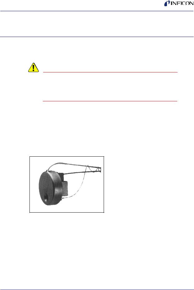
The CrystalSix® sensor is a (six crystal) quartz crystal deposition monitor transducer. When the monitor crystal being used fails a new crystal is advanced into position, fully replacing that crystal’s function. The mechanism used for providing this motion is pneumatically powered. The logic for automatic operation of this transducer is conveniently provided on most current INFICON Deposition Controllers. It is manufactured under US Patent #5,025,644, with foreign patents pending.
Figure 1-1 CrystalSix Sensor
IPN 074-155L
Table 1-1 Sensor specification
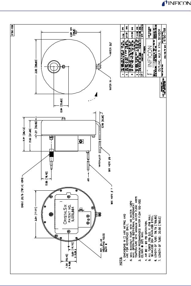
Maximum bakeout temp with no water |
130 °C |
|
|
Maximum operating isothermal |
400 °C |
environment temperature with minimum |
|
water flow |
|
|
|
Size (maximum envelope) |
3.8" (9.7 cm) DIA x 2.0" (5.1 cm) high |
|
|
1 - 1

CrystalSix Operating Manual
Table 1-1 Sensor specification (continued)
Water, air and coax length |
Standard 30" (76 cm) |
|
|
Crystal exchange |
Front-loading, extraction tool required |
|
(supplied with unit) |
|
|
Mounting |
Six #4-40 tapped holes on the back of the |
|
sensor body |
|
|
1.1.1 Installation Requirements
1.1.1.1Feedthrough
Qty (1) 2-3/4" ConFlat® with two coaxial feedthroughs, two pass water, one air IPN 002-080, See Figure 5-2 on page 5-2 or,
Qty (1) 1" bolt with one coaxial feedthrough, two pass water, one air IPN 750-030-G1, see Figure 5-1 on page 5-1.
1.1.1.2Other
User to provide vacuum-tight braze joints or connectors for the water and air tubes.
Valve assembly for air, IPN 750-420-G1 (not provided), with a 0.022" restrictor orifice installed by the user. (Orifice included with CrystalSix accessory kit.) See Table 1-3 on page 1-3.
XIU or Oscillator designed to interface with the deposition controller.
Deposition controller must have been designed for this specific crystal sensor (INFICON® XTC/2, XTC/C, IC/4, IC/4 PLUS, IC/5).
1.1.1.3Utilities
Minimum water flow 150-200 cc/min, 30 °C max (Do not allow water to freeze). Coolant should not contain chlorides as stress corrosion cracking may occur.
Regulated air supply 80-90 PSIG (5.5 bar - 6.2 bar) [550 kPa - 620 kPa]
2 meter maximum length of 1/8" tubing between bellows assembly and the control valve.
CAUTION
Do not allow water tubes to freeze. This may happen if the tubes pass through a cryogenic shroud and the fluid’s flow is interrupted.
IPN 074-155L
1 - 2
IPN 074-155L
|
|
|
CrystalSix Operating Manual |
|
|
|
|
|
|
1.1.2 Materials |
|
|
||
|
|
Table 1-2 Materials |
|
|
|
|
|
|
|
|
|
Plate, Holders, Material Shield, |
304 type stainless steel |
|
|
|
Mechanical Parts |
|
|
|
|
|
|
|
|
|
Springs, Electrical Contacts |
Au plated Be-Cu, Au Plate Inconel®, 303 |
|
|
|
|
stainless steel |
|
|
|
|
|
|
|
|
Water and air tubes |
S-304, 0.125" (0.32 cm) O.D. x .016" (.04 |
|
|
|
|
cm) Wall Thickness 30" Long (76 cm) |
|
|
|
|
Seamless Stainless Steel Tubing |
|
|
|
|
|
|
|
|
Connector (Microdot) |
Stainless steel |
|
|
|
|
|
|
|
|
Insulators |
>99% A12O3 |
|
|
|
|
|
|
|
|
Cable |
Teflon® insulated copper |
|
|
|
|
|
|
|
|
Crystal |
0.550" Diameter |
|
|
|
|
|
|
|
|
Body and Carousel |
2024 T351 Aluminum |
|
|
|
|
|
|
1.1.3 Unpacking Instructions
The CrystalSix sensor and accessories are packaged in a single cardboard carton with rigid foam inserts.
Carefully remove the packaged accessories before removing the sensor, then remove the red shipping plug from the sensor carousel.
1.1.4 Inventory
In addition to the basic transducer, the complete shipping package includes an accessory kit (IPN 750-268-G1) which consists of the following:
Table 1-3 Contents of Accessory Kit
Qty |
IPN |
Description |
|
|
|
X |
750-268-G1 |
Accessory Kit, CrystalSix Sensor |
|
|
|
1 |
750-254-G1 |
Assembly, Alignment Tool |
|
|
|
1 |
750-279-P1 |
Crystal Puller |
|
|
|
1 |
074-5000-G1 |
Thin Film Manuals CD |
|
|
|
1 |
008-010-G10 |
Assembly, Sensor Crystal 6MHz |
|
|
|
1 |
059-189 |
CC-1010-0225 Orifice 0.0225" diameter |
|
|
|
2 |
070-201 |
#4 Split Lock Washer, Stainless Steel |
|
|
|
2 |
084-032 |
#4-40x0.375" Long Socket Head Cap Screw, Stainless Steel |
|
|
|
1 - 3

CrystalSix Operating Manual
Table 1-3 Contents of Accessory Kit (continued)
Qty |
IPN |
Description |
|
|
|
2 |
084-039 |
#4-40x0.500" Long Socket Head Cap Screw, Stainless Steel |
|
|
|
2 |
084-084 |
#4-40x0.688" Long Socket Head Cap Screw, Stainless Steel |
|
|
|
1 |
070-828 |
Hex Wrench 1/16" SC9-3 |
|
|
|
1 |
070-829 |
Hex Wrench 3/32" SC9-5 |
|
|
|
1 |
070-1175 |
Hex Wrench 5/64" SC9-4 |
|
|
|
1 |
750-037-G1 |
Spring Tube Bender Kit |
|
|
|
1 |
008-007 |
Crystal Snatcher |
|
|
|
1 |
750-191-G1 |
Molybdenum disulfide in Alcohol |
|
|
|
IPN 074-155L
1 - 4
CrystalSix Operating Manual
|
|
Figure 1-2 Outline Multi Crystal Sensor
IPN 074-155L
1 - 5

CrystalSix Operating Manual
Figure 1-3 Assembly CrystalSix Sensor
IPN 074-155L
1 - 6
IPN 074-155L
CrystalSix Operating Manual
Chapter 2
Sensor Installation
Successful operation of any crystal sensor depends on proper placement, compatibility of its construction with its operating environment and connection to proper utilities.
NOTE: The sensor head, water tubes, cable, etc. should be clean and grease free when installed in the vacuum chamber. These parts should be handled while wearing clean nylon gloves. If parts do become contaminated, clean them thoroughly using a suitable solvent to avoid outgassing and excessive peeling of deposition material from the sensor’s surfaces.
CAUTION
Incorrect rotation direction will cause permanent damage rendering transducer inoperative. Refer to Figure 1-2 on page 1-5 for proper direction of rotation.
2.1 Crystals in the CrystalSix Sensor
2.1.1 Handle the Crystal with Care
Always use clean nylon lab gloves and clean plastic tweezers when handling the crystal. Handle the crystals only by their edges. Anything that comes in contact with the crystal surfaces may leave contamination, which may lead to poor film adhesion. Poor film adhesion will result in high rate noise and premature crystal failure.
CAUTION
Do not use metal tweezers to handle crystals. Metal tweezers may chip the edge of the crystal.
2 - 1
CrystalSix Operating Manual
2.1.2 Care of the Ceramic Retainer
CAUTION
Do not use excessive force when handling the Ceramic Retainer Assembly since breakage may occur. Always use the crystal snatcher.
To prevent scratching the crystal electrode, do not rotate the ceramic retainer after installation.
Always use clean nylon lab gloves and plastic tweezers for handling the crystal. This avoids contamination which may lead to poor adhesion of deposited material to the electrode.
Follow the procedure below to install or replace the crystals in the CrystalSix sensor. (Reference Figure 1-3 on page 1-6).
CAUTION
Rotating the unit in the wrong direction with the stops disabled will cause severe damage! Do not rotate the unit by hand to install the crystals or to check indexing.
1Remove the heat shield (item #8) by gently pulling on the outside circumference of the shield. The shield should snap off.
2Since the crystal holders are packaged separately, skip the remainder of this step for first-time installations. Using the crystal puller (IPN 750-279-P1, provided in ship kit 750-268), remove the crystal holder by pushing the tips of the crystal puller over the outside circumference of the crystal holder (see Figure 2-2 on page 2-4). Gently pull the crystal holder from its receptacle. A slight amount of pressure applied to collapse the tips of the crystal puller may be required to extract the crystal holder.
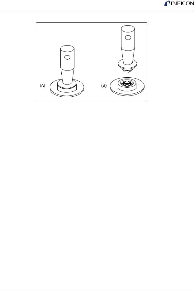
3Insert the tapered end of the crystal snatcher (part number 008-007) into the ceramic retainer (A) and apply a small amount of pressure. This locks the retainer to the snatcher and allows the retainer to be pulled straight out (B). See Figure 2-1.
IPN 074-155L
2 - 2
IPN 074-155L
CrystalSix Operating Manual
Figure 2-1 Using the Crystal Snatcher
4Invert the crystal holder and the crystal will drop out. (Skip this step for first-time installations.)
5Install the new crystal per section 2.1.1 on page 2-1 and section 2.1.2 on page 2-2.
6Using clean nylon gloves, grasp the edge of the new crystal with a clean pair of plastic tweezers. Orient the crystal so the patterned electrode is facing up. Gently insert the edge of the crystal beneath one of the wire segments that protrude into the crystal cavity. Release the crystal.
7Replace the ceramic retainer. Initially orient it at an angle to displace the spring wire segments in the crystal holder.
8Release the crystal snatcher with a slight side-to-side rocking motion. Using the backside of the crystal snatcher, push on the ceramic retainer to ensure it is completely seated.
9Position the crystal holder between the tips of the crystal puller as illustrated in Figure 2-2.
10Push the crystal holder into the receptacle of the CrystalSix sensor until completely seated. “Snap” the crystal puller to one side to release the crystal holder from the crystal puller. Using the non-slotted end of the crystal puller, apply pressure to the crystal holder until it is completely seated. Verify that the crystal fail signal on the controller display disappears. If the crystal fail signal does not disappear, consult section 4.5 on page 4-9.
11Press the crystal switch button on the hand held controller or the controller front panel. The sensor will advance to the next crystal position. Repeat procedure from Step 2 until all six new crystals have been installed.
12Install the heat shield (item #8) by first orienting the slot in the heat shield to accommodate the water tubes, then secure the heat shield by applying pressure near the center of the shield. The shield should snap in place.
2 - 3
Loading...