


 Loading...
O P E R A T I O N A N D S E R V I C E M A N U A L
RQCM
Research Quartz Crystal Microbalance
PN 603800 Rev.K

O P E R A T I O N A N D S E R V I C E M A N U A L
RQCM
Research Quartz Crystal Microbalance
IPN 603800 Rev.K


 ®
®
www.inficon.com reachus@inficon.com
Due to our continuing program of product improvements, specifications are subject to change without notice. ©2014 INFICON

Trademarks
The trademarks of the products mentioned in this manual are held by the companies that produce them.
All other brand and product names are trademarks or registered trademarks of their respective companies.
Disclaimer
The information contained in this manual is believed to be accurate and reliable. However, INFICON assumes no responsibility for its use and shall not be liable for any special, incidental, or consequential damages related to the use of this product.
Disclosure
The disclosure of this information is to assist owners of INFICON equipment to properly operate and maintain their equipment, and does not constitute the release of rights thereof. Reproduction of this information and equipment described herein is prohibited without prior written consent from INFICON, Two Technology Place, East Syracuse, NY 13057-9714. Phone 315.434.1100. See www.inficon.com.
Copyright
©2014 All rights reserved.
Reproduction or adaptation of any part of this document without permission is unlawful.
WARNING
All standard safety procedures associated with the safe handling of electrical equipment must be observed. Always disconnect power when working inside the controller. Only properly trained personnel should attempt to service the instrument.

DECLARATION
OF
CONFORMITY
This is to certify that this equipment, designed and manufactured by:
INFICON Inc.
Two Technology Place
East Syracuse, NY 13057
USA
meets the essential safety requirements of the European Union and is placed on the market accordingly. It has been constructed in accordance with good engineering practice in safety matters in force in the Community and does not endanger the safety of persons, domestic animals or property when properly installed and maintained and used in applications for which it was made.
Equipment Description: |
RQCM (Research Quartz Crystal Microbalance) Thin Film Deposition |
|
Controller, including the SO-100 Oscillator Package. |
Applicable Directives: |
73/23/EEC as amended by 93/68/EEC (LVD) |
|
89/336/EEC as amended by 93/68/EEC (EMC) |
|
2002/95/EC (RoHS) |
Applicable Standards: |
EN 61010-1:2001 (Safety) |
|
EN 61326-1:1997/A1:1998/A2:2001, Class A: Emissions per Table 3 |
|
Immunity per Table A.1 |
|
Due to the classification of this product it is currently |
|
exempt from the RoHS directive. |
CE Implementation Date: |
October 1, 2007 |
Authorized Representative: |
Duane H. Wright |
|
Quality Assurance Manager, ISS |
|
INFICON Inc. |
ANY QUESTIONS RELATIVE TO THIS DECLARATION OR TO THE SAFETY OF INFICON'S PRODUCTS SHOULD BE DIRECTED, IN WRITING, TO THE QUALITY ASSURANCE DEPARTMENT AT THE ABOVE ADDRESS.
10/01/07

Warranty
INFICON warrants the product to be free of functional defects in material and workmanship and that it will perform in accordance with its published specification for a period of (twenty-four) 24 months.
The foregoing warranty is subject to the condition that the product be properly operated in accordance with instructions provided by INFICON or has not been subjected to improper installation or abuse, misuse, negligence, accident, corrosion, or damage during shipment.
Purchaser's sole and exclusive remedy under the above warranty is limited to, at INFICON's option, repair or replacement of defective equipment or return to purchaser of the original purchase price. Transportation charges must be prepaid and upon examination by INFICON the equipment must be found not to comply with the above warranty. In the event that INFICON elects to refund the purchase price, the equipment shall be the property of INFICON.
This warranty is in lieu of all other warranties, expressed or implied and constitutes fulfillment of all of INFICON's liabilities to the purchaser. INFICON does not warrant that the product can be used for any particular purpose other than that covered by the applicable specifications. INFICON assumes no liability in any event, for consequential damages, for anticipated or lost profits, incidental damage of loss of time or other losses incurred by the purchaser or third party in connection with products covered by this warranty or otherwise.
www.inficon.com reachus@inficon.com
TABLE OF CONTENTS
1 GENERAL DESCRIPTION ................................................................................................... |
1-1 |
|
1.1 |
FEATURES................................................................................................................................. |
1-1 |
1.1.1 |
VERY WIDE FREQUENCY RANGE................................................................................... |
1-1 |
1.1.2 |
SUPPORT FOR VERY LOW Q, HIGHLY DAMPED, CRYSTALS...................................... |
1-1 |
1.1.3DIRECT REAL-TIME MEASUREMENTS OF CRYSTAL FREQUENCY, MASS, AND
|
RESISTANCE ...................................................................................................................................... |
1-1 |
|||
|
1.1.4 |
|
MULTIPLE CRYSTAL MEASUREMENT CHANNELS....................................................... |
1-2 |
|
|
1.1.5 |
|
ELECTRODE CAPACITANCE CANCELLATION.............................................................. |
1-2 |
|
|
1.1.6 |
|
“AUTOLOCK”.................................................................................................................... |
1-2 |
|
|
1.1.7 |
|
CRYSTAL FACE ISOLATION ............................................................................................. |
1-2 |
|
|
1.1.8 |
|
FULLY INTERGATED COMPUTER SOFTWARE ............................................................. |
1-2 |
|
|
1.1.9 |
|
INPUTS AND OUTPUTS CAPABILITY.............................................................................. |
1-2 |
|
|
1.1.10 |
DATA ACQUISITION.......................................................................................................... |
1-2 |
||
|
1.2 |
|
SPECIFICATIONS ..................................................................................................................... |
1-3 |
|
|
1.2.1 |
|
CRYSTAL MEASUREMENT ............................................................................................... |
1-3 |
|
|
1.2.2 |
|
DATA ACQUISITION ANALOG CARD (OPTIONAL) ....................................................... |
1-3 |
|
|
|
1.2.2.1 |
Analog Inputs .................................................................................................................. |
1-3 |
|
|
|
1.2.2.2 |
Thermocouple Input......................................................................................................... |
1-4 |
|
|
|
1.2.2.3 |
RTD Input........................................................................................................................ |
1-4 |
|
|
|
1.2.2.4 |
Thermistor Input .............................................................................................................. |
1-4 |
|
|
1.2.3 |
|
I/O CARD (OPTIONAL)...................................................................................................... |
1-4 |
|
|
1.2.4 |
|
COMMUNICATIONS.......................................................................................................... |
1-4 |
|
|
1.2.5 |
|
FRONT PANEL INDICATORS............................................................................................ |
1-4 |
|
|
1.2.6 |
|
POWER REQUIREMENTS ................................................................................................. |
1-4 |
|
|
1.2.7 |
|
PHYSICAL........................................................................................................................... |
1-4 |
|
|
1.3 |
|
ACCESSORIES .......................................................................................................................... |
1-5 |
|
|
1.4 |
|
OPTIONAL CARDS ................................................................................................................... |
1-5 |
|
2 |
GETTING STARTED ............................................................................................................ |
2-1 |
|||
|
2.1 |
|
UNPACKING.............................................................................................................................. |
2-1 |
|
|
2.2 |
|
SAFETY PRECAUTION............................................................................................................ |
2-1 |
|
|
2.2.1 |
|
LINE VOLTAGE.................................................................................................................. |
2-1 |
|
|
2.2.2 |
|
GROUNDING...................................................................................................................... |
2-1 |
|
|
2.2.3 |
|
LINE FUSES........................................................................................................................ |
2-1 |
|
|
2.3 |
|
SYSTEM CHECKOUT............................................................................................................... |
2-1 |
|
|
2.3.1 |
|
CRYSTAL MEASUREMENTS VERIFICATION .................................................................. |
2-2 |
|
|
|
2.3.1.1 |
In Air ............................................................................................................................... |
2-2 |
|
|
|
2.3.1.2 |
In Water ........................................................................................................................... |
2-3 |
|
3 |
OPERATION ......................................................................................................................... |
3-1 |
|||
|
3.1 |
GENERAL DESCRIPTION OF THE CRYSTAL MEASUREMENT........................................ |
3-1 |
||
|
3.2 |
UNDERSTANDING AND SETTING UP A CRYSTAL MEASUREMENT CHANNEL ......... |
3-2 |
||
|
3.3 |
|
FRONT PANEL DESCRIPTION................................................................................................ |
3-2 |
|
|
3.3.1 |
|
LOCK INDICATOR............................................................................................................. |
3-2 |
|
|
3.3.2 |
|
UNLOCK INDICATOR ....................................................................................................... |
3-2 |
|
|
3.3.3 |
|
SWEEP INDICATOR........................................................................................................... |
3-2 |
|
|
3.3.4 |
|
RESET SWITCH .................................................................................................................. |
3-2 |
|
|
3.3.5 |
|
CRYSTAL CONNECTOR..................................................................................................... |
3-2 |
|
|
3.3.6 |
|
CRYSTAL FACE CONNECTOR.......................................................................................... |
3-2 |
|
|
|
3.3.6.1 Crystal Face Mating Connector ....................................................................................... |
3-3 |
||
|
3.3.7 |
|
FINE AND COURSE CAPACITANCE ADJUSTMENTS .................................................... |
3-3 |
|
|
3.4 |
ADJUSTING THE CAPACITANCE CANCELLATION........................................................... |
3-5 |
||
iv
3.5 |
ADJUSTING CAPACITANCE CANCELLATION TRIMMER & SWITCH............................ |
3-5 |
3.5.1 AS A GENERAL RULE........................................................................................................ |
3-6 |
|
3.6 |
WORKING WITH VERY LOW Q CRYSTALS ........................................................................ |
3-7 |
3.7 |
NORMAL OPERATION ............................................................................................................ |
3-7 |
3.8 |
HOOKUP FOR ELECTROCHEMICAL EXPERIMENTS ........................................................ |
3-7 |
3.9 |
OPERATION GUIDELINES ...................................................................................................... |
3-9 |
3.9.1 ALLOW THE RQCM TO WARM UP .................................................................................. |
3-9 |
|
3.9.2 ISOLATE THE RQCM FROM TEMPERATURE CHANGE ............................................... |
3-9 |
|
3.9.3 FOR OPERATION IN AIR................................................................................................... |
3-9 |
|
|
3.9.3.1 Operate at or Near The Crystal’s “Turn-Around-Point”................................................ |
3-10 |
|
|
3.9.3.2 |
Control The Temperature .............................................................................................. |
3-10 |
|
3.9.3.3 Keep the Test Chamber Clean ....................................................................................... |
3-10 |
|
|
3.9.3.4 Keep a Constant Gas Flow ............................................................................................ |
3-10 |
|
3.9.4 |
FOR OPERATION IN LIQUIDS ....................................................................................... |
3-10 |
|
|
3.9.4.1 Degas The Sample Liquid ............................................................................................. |
3-10 |
|
|
3.9.4.2 Wait For Mechanical Disturbances To Stabilize ........................................................... |
3-10 |
|
|
3.9.4.3 Wait For The Temperature To Stabilize ........................................................................ |
3-10 |
|
|
3.9.4.4 Prepare Your Solutions Carefully.................................................................................. |
3-11 |
|
|
3.9.4.5 Avoid Using A Stirrer.................................................................................................... |
3-11 |
|
3.9.5 |
FOR OPERATION WITH THE FC-550 FLOW CELL...................................................... |
3-11 |
|
|
3.9.5.1 Avoid Excessive Differential Pressure .......................................................................... |
3-11 |
|
|
3.9.5.2 Keep a Constant Line Pressure ...................................................................................... |
3-11 |
|
|
3.9.5.3 Allow Ample Time For the Crystal To Come to Equilibrium....................................... |
3-11 |
|
4 CRYSTALS, HOLDERS AND FLOW CELL ........................................................................ |
4-1 |
||
4.1 1 INCH DIAMETER CRYSTALS .............................................................................................. |
4-1 |
||
4.1.1 |
ELECTRODE CONFIGURATION...................................................................................... |
4-1 |
|
4.1.2 |
CRYSTAL PARAMETERS ................................................................................................... |
4-2 |
|
4.1.3 |
CRYSTAL SURFACE FINISH ............................................................................................. |
4-3 |
|
4.1.4 |
CRYSTAL ELECTRODE MATERIALS................................................................................ |
4-3 |
|
4.1.5 |
CRYSTAL THICKNESS ....................................................................................................... |
4-3 |
|
4.1.6 |
MASS SENSITIVITY ............................................................................................................ |
4-3 |
|
4.1.7 |
STABILITY........................................................................................................................... |
4-4 |
|
4.1.8 |
CRYSTAL LIFE EXPECTANCY .......................................................................................... |
4-4 |
|
4.1.9 |
TEMPERATURE COEFFICIENT ....................................................................................... |
4-5 |
|
4.2 CRYSTAL CARE AND HANDLING ........................................................................................ |
4-7 |
||
4.2.1 |
CRYSTAL CLEANING......................................................................................................... |
4-8 |
|
|
4.2.1.1 |
General Cleaning ............................................................................................................. |
4-8 |
|
4.2.1.2 |
Organic (hydrocarbon contaminants) .............................................................................. |
4-8 |
|
4.2.1.3 Biomaterials (lipids, proteins and similar biomolecules)................................................. |
4-8 |
|
|
4.2.1.4 Lipid vesicles on SiO2 surfaces........................................................................................ |
4-8 |
|
|
4.2.1.5 |
Polystyrene removal ........................................................................................................ |
4-8 |
|
4.2.1.6 |
Polymer Removal ............................................................................................................ |
4-8 |
4.2.2 |
ELECTRODE SURFACE MODIFICATIONS ..................................................................... |
4-9 |
|
|
4.2.2.1 |
SPIN COATING.............................................................................................................. |
4-9 |
|
4.2.2.2 |
SELF-ASSEMBLED MONOLAYERS (SAM) .............................................................. |
4-9 |
|
4.2.2.3 PHYSICAL VACUUM DEPOSITION (PVD) ............................................................... |
4-9 |
|
4.3 |
CRYSTAL HOLDERS.............................................................................................................. |
4-10 |
|
4.3.1 |
HOW TO INSTALL A CRYSTAL IN A INFICON CRYSTAL HOLDER............................. |
4-10 |
|
4.3.2 |
HOLDER CARE AND HANDLING................................................................................... |
4-12 |
|
4.3.3 |
CONSIDERATIONS FOR BUILDING YOUR OWN HOLDER ........................................ |
4-13 |
|
4.4 |
FLOW CELL............................................................................................................................. |
4-13 |
|
5 THEORY OF OPERATION................................................................................................... |
5-1 |
||
5.1 |
SAUERBREY EQUATION ........................................................................................................ |
5-1 |
|
5.2 |
Z-MATCH EQUATION.............................................................................................................. |
5-2 |
|
v
5.3 |
THICKNESS CALCULATION .................................................................................................. |
5-3 |
|
5.4 |
LIQUID MEASUREMENTS ...................................................................................................... |
5-5 |
|
|
5.4.1 DECAY LENGTH OF SHEAR WAVE IN LIQUID.............................................................. |
5-8 |
|
5.5 |
DISSIPATION METHOD........................................................................................................... |
5-9 |
|
5.6 |
ELECTRICAL DESCRIPTION OF THE QUARTZ CRYSTAL................................................ |
5-9 |
|
5.7 |
CHARACTERIZING THE CRYSTAL MEASUREMENT...................................................... |
5-15 |
|
|
5.7.1 |
FREQUENCY ERRORS..................................................................................................... |
5-16 |
|
5.7.2 FREQUENCY ERROR DUE TO PHASE ERROR............................................................. |
5-16 |
|
|
5.7.3 FREQUENCY ERROR DUE TO IMPERFECT CAPACITANCE CANCELLATION........ |
5-17 |
|
5.8 |
FREQUENCY ERRORS DUE TO IMPERFECT CAPACITANCE CANCELLATION ......... |
5-18 |
|
5.9 |
CALCULATING CRYSTAL POWER ..................................................................................... |
5-19 |
|
6 |
APPLICATIONS.................................................................................................................... |
6-1 |
|
6.1 |
ELECTROCHEMICAL QUARTZ CRYSTAL MICROBALANCE .......................................... |
6-1 |
|
|
6.1.1 |
CALIBRATION .................................................................................................................... |
6-1 |
|
6.1.2 |
POLYMER MODIFIED ELECTRODES ............................................................................. |
6-2 |
6.2 |
CHEMICAL AND BIOLOGICAL SENSORS............................................................................ |
6-2 |
|
7 |
COMPUTER INTERFACE .................................................................................................... |
7-1 |
|
7.1 |
COMPUTER INTERFACE SOFTWARE................................................................................... |
7-1 |
|
7.2 |
RECOMMENDED MINIMUM COMPUTER CONFIGURATION .......................................... |
7-1 |
|
7.3 |
SOFTWARE INSTALLATION.................................................................................................. |
7-1 |
|
7.4 |
CREATING YOUR OWN SOFTWARE .................................................................................... |
7-1 |
|
7.5 |
RS-232 SERIAL INTERFACE ................................................................................................... |
7-1 |
|
7.6 |
RS-485 SERIAL INTERFACE ................................................................................................... |
7-2 |
|
7.7 |
IEEE-488 PARALLEL INTERFACE ......................................................................................... |
7-3 |
|
7.8 |
PROTOCOL................................................................................................................................ |
7-4 |
|
7.9 |
DATA TYPES............................................................................................................................. |
7-4 |
|
7.10 |
MESSAGE RECEIVED STATUS .............................................................................................. |
7-4 |
|
7.11 |
INSTRUCTION SUMMARY ..................................................................................................... |
7-5 |
|
7.12 |
INSTRUCTION DESCRIPTIONS.............................................................................................. |
7-5 |
|
8 DATA ACQUISITION CARD (OPTIONAL) .......................................................................... |
8-1 |
||
8.1 |
VOLTAGE INPUTS ................................................................................................................... |
8-1 |
|
8.2 |
TEMPERATURE INPUTS ......................................................................................................... |
8-2 |
|
|
8.2.1 |
THERMISTOR INPUT......................................................................................................... |
8-2 |
|
8.2.2 |
RTD INPUT ......................................................................................................................... |
8-2 |
|
8.2.3 |
THERMOCOUPLE INPUT ................................................................................................. |
8-2 |
8.3 |
GROUNDING CONSIDERATION............................................................................................ |
8-3 |
|
|
8.3.1 |
VOLTAGE MEASUREMENT GROUNDING...................................................................... |
8-3 |
|
8.3.2 |
TEMPERATURE MEASUREMENT GROUNDING............................................................ |
8-3 |
9 |
I/O CARD (OPTIONAL) ........................................................................................................ |
9-1 |
|
10 |
TROUBLESHOOTING GUIDE........................................................................................ |
10-1 |
|
11 |
GLOSSARY..................................................................................................................... |
11-1 |
|
12 |
REFERENCES ................................................................................................................ |
12-1 |
|
vi
Table of Figures
FIGURE 1 CRYSTAL FACE MATING CONNECTOR .......................................................................................... |
3-3 |
FIGURE 2 CRYSTAL CHANNEL DESCRIPTION................................................................................................ |
3-4 |
FIGURE 3 CAPACITANCE ADJUSTMENTS....................................................................................................... |
3-6 |
FIGURE 4 TYPICAL CONNECTIONS FOR AN ELECTROCHEMICAL QCM EXPERIMENT .................................. |
3-8 |
FIGURE 5 TYPICAL VOLTAMMOGRAM PLOT OBTAINED USING THE RQCM................................................. |
3-9 |
FIGURE 6 RQCM FRONT PANEL................................................................................................................. |
3-12 |
FIGURE 7 RQCM REAR PANEL .................................................................................................................. |
3-13 |
FIGURE 8 INFICON 1-INCH DIAMETER CRYSTALS – ELECTRODE CONFIGURATION.................................... |
4-2 |
FIGURE 9 INFICON 1" CRYSTAL - AS SEEN FROM THE FRONT SIDE ............................................................. |
4-2 |
FIGURE 10 FREQUENCY VS. TEMPERATURE OF INFICON 1" AT-CUT CRYSTAL FOR 90 C ............................ |
4-6 |
FIGURE 11 FREQUENCY VS. TEMPERATURE OF INFICON 1" AT-CUT CRYSTAL FOR 25 C ............................ |
4-7 |
FIGURE 12 CHC-100 CRYSTAL HOLDER .................................................................................................... |
4-10 |
FIGURE 13 CRYSTAL INSTALLATION .......................................................................................................... |
4-11 |
FIGURE 14 FREQUENCY CHANGE VS. WT % GLYCEROL............................................................................... |
5-7 |
FIGURE 15 RESISTANCE CHANGE VS. WT % GLYCEROL .............................................................................. |
5-8 |
FIGURE 16 CRYSTAL EQUIVALENT CIRCUIT................................................................................................. |
5-9 |
FIGURE 17 POLAR PLOT OF CRYSTAL ADMITTANCE .................................................................................. |
5-10 |
FIGURE 18 ADMITTANCE VS. FREQUENCY, MAGNITUDE AND PHASE OF HIGH Q CRYSTAL ....................... |
5-11 |
FIGURE 19 ADMITTANCE VS. FREQUENCY, REAL AND IMAGINARY COMPONENTS OF HIGH Q CRYSTAL ... |
5-11 |
FIGURE 20 POLAR ADMITTANCE PLOT OF HIGH Q CRYSTAL ..................................................................... |
5-12 |
FIGURE 21 POLAR ADMITTANCE PLOT OF LOW Q CRYSTAL ...................................................................... |
5-13 |
FIGURE 22 ADMITTANCE VS. FREQUENCY, REAL AND IMAGINARY COMPONENTS OF LOW Q CRYSTAL .... |
5-13 |
FIGURE 23 ADMITTANCE VS. FREQUENCY, MAGNITUDE AND PHASE OF LOW Q CRYSTAL ........................ |
5-14 |
FIGURE 24 NON-ZERO PHASE LOCK ........................................................................................................... |
5-15 |
FIGURE 25 EQUIVALENT PHASE ERROR DUE TO IMPERFECT CAPACITANCE CANCELLATION.................... |
5-17 |
FIGURE 26 FREQUENCY ERROR DUE TO IMPERFECT CAPACITANCE CANCELLATION ................................. |
5-19 |
FIGURE 27 CRYSTAL POWER DISSIPATION VS. CRYSTAL RESISTANCE ....................................................... |
5-20 |
FIGURE 28 D9S DTE REAR-PANEL RS-232 SOCKET CONNECTOR ................................................................ |
7-2 |
FIGURE 29 IEEE-488 CONNECTOR............................................................................................................... |
7-3 |
FIGURE 30 DB25P DATA ACQUISITION REAR PANEL CONNECTOR.............................................................. |
8-1 |
FIGURE 31 REAR PANEL TYPE T THERMOCOUPLE CONNECTOR .................................................................. |
8-2 |
FIGURE 32 DB73P I/O REAR PANEL CONNECTOR........................................................................................ |
9-1 |
vii
List of Tables
TABLE 5-1 MATERIAL DENSITY AND ACOUSTIC IMPEDANCE VALUE........................................................... |
5-4 |
TABLE 7-1 D9 REAR PANEL RS-232/RS-485 CONNECTOR PIN ASSIGNMENTS ............................................ |
7-2 |
TABLE 7-2 IEEE-488 PIN ASSIGNMENTS ..................................................................................................... |
7-4 |
TABLE 8-1 DB25P DATA ACQUISION REAR PANEL CONNECTOR PIN ASSIGNMENTS................................... |
8-1 |
TABLE 8-2 INPUT VOLTAGE RESOLUTION .................................................................................................... |
8-1 |
TABLE 9-1 DB37P I/O REAR PANEL CONNECTOR PIN ASSIGNMENTS......................................................... |
9-1 |
viii

RQCM – RESEARCH QUARTZ CRYSTAL MICROBALANCE
1 GENERAL DESCRIPTION
The RQCM is designed for many types of research applications where QCM (Quartz Crystal Microbalance) measurement is desired. Included with each instrument is a Windows™ based software package that allows the user to configure the RQCM, setup multiple experiments, log data with real-time graphing and review results from previous experiments.
The QCM portion of this system accurately measures crystal frequency and crystal resistance for up to three crystals simultaneously. The software uses this data to derive various physical parameters of the deposited film and/or the liquid or gas environment at the surface of the crystal. The heart of the system is a high performance phase lock oscillator (PLO) circuit that provides superior measurement stability over a wide frequency range (3.8 to 6.06 MHz, or 5.1 to 10 MHz). The circuit incorporates adjustable crystal capacitance cancellation reducing error caused by the parasitic capacitance of the crystal, cable and fixture. Capacitance cancellation is essential for accurate measurements of lossy (soft) films.
Data collection from external sources is accomplished with an optional Data Acquisition Card, which provides three temperature inputs (RTD, Thermocouple and Thermistor) as well as five scalable analog inputs. For example, you can use the analog inputs to acquire potential and current data from a potentiostat during a cyclic voltammogram. The RQCM allows you to combine this data with the mass data of the QCM to create a graph of mass and current versus potential.
Control of external instruments and peripheral devices is accomplished with an optional input/output card. Each remote I/O card provides eight remote inputs and eight relay outputs. The functions of the inputs and outputs are defined in the RQCM’s software with some typical uses including the control of pumps, heaters, valves, instrument initiation, etc.
1.1FEATURES
1.1.1VERY WIDE FREQUENCY RANGE
The RQCM supports a wide frequency range from 3.8 to over 6 MHz. It will support both 5 and 6 MHz crystals; and with a low limit of 3.8 MHz it will support 1.2 MHz of frequency shift on a 5MHz crystal. A frequency range of 5.1 to over 10 MHz is also available.
1.1.2SUPPORT FOR VERY LOW Q, HIGHLY DAMPED, CRYSTALS
The RQCM will accurately measure crystals with resistances up to 5 KΩ. In most cases
it will maintain lock up to a resistance of 10 KΩ or more. It will support crystal oscillation in highly viscous solutions of more than 88% glycol in water.
1.1.3DIRECT REAL-TIME MEASUREMENTS OF CRYSTAL FREQUENCY, MASS, AND RESISTANCE
The RQCM accurately measures crystal frequency, mass, and resistance. The software uses this data to derive various physical parameters of the deposited film or media at the surface of the crystal.
GENERAL DESCRIPTION 1-1

RQCM – RESEARCH QUARTZ CRYSTAL MICROBALANCE
1.1.4MULTIPLE CRYSTAL MEASUREMENT CHANNELS
The RQCM can be configured to measure up to three crystal measurement channels simultaneously.
1.1.5ELECTRODE CAPACITANCE CANCELLATION
The total quartz crystal impedance includes a shunt capacitance (due to the capacitance of the crystal electrodes, cable and holder) in parallel with the series resonant arm. The total current through the crystal is the sum of the current through the shunt capacitance plus the current through the series resonant arm. The physical motion of the crystal is reflected in the values of the L, R and C in the series arm of the crystal only, and therefore we want to subtract out or otherwise cancel the current through the shunt electrode capacitance. The Crystal Measurement Card includes a method of canceling the electrode capacitance insuring that the measured crystal current does not include the current through the electrode capacitance and therefore is essentially the current through the series resonant arm of the crystal only.
1.1.6“AUTOLOCK”
When the PLO loses lock, the VCO (Voltage Controlled Oscillator) is ramped up to the maximum frequency at which time it is automatically reset to the minimum frequency and a new scan is initiated.
To insure that the VCO ramps up in frequency, a small amount of quadrature current is injected into the current to voltage buffer whenever the PLO is unlocked. This current is equivalent to a shunt capacitance of about 1.5 pfd. As soon as lock is detected, the quadrature current is turned off.
1.1.7CRYSTAL FACE ISOLATION
The Crystal face is galvanically (transformer) isolated from earth ground. The Crystal Face connection allows the crystal face electrode to be easily connected to an external voltage or current source such as a potentiostat.
1.1.8FULLY INTERGATED COMPUTER SOFTWARE
Computer software is included with each RQCM, allowing the user to set up, graph and log frequency and resistance of the crystals from a computer. It also allows the setup, graphing and logging of temperature and analog data – if the hardware is installed.
1.1.9INPUTS AND OUTPUTS CAPABILITY
As an option, the RQCM can be outfitted with an I/O Card. This card provides eight remote discrete inputs and eight relay outputs. These I/O’s can be used to monitor or control external instruments and peripheral devices.
1.1.10 DATA ACQUISITION
To support the simultaneous logging and display of additional analog information, such as voltage, current, or temperature, the RQCM can be outfitted with an optional Data Acquisition Card. This card supports three types of temperature sensors (RTD, Thermocouple and Thermistor) as well as five scalable analog inputs.
1-2 GENERAL DESCRIPTION

RQCM – RESEARCH QUARTZ CRYSTAL MICROBALANCE
1.2 |
SPECIFICATIONS |
|
|
1.2.1 |
CRYSTAL MEASUREMENT |
|
|
|
|
||
Crystal measurement channels: |
One standard, three maximum. |
||
Frequency range: |
3.8 to 6.06 MHz, or 5.1 to 10 MHz |
||
Frequency resolution: |
0.03 Hz @ 6.0MHz |
||
Mass resolution: |
<0.4 ng/cm2 (0.014 Å Aluminum) |
||
Capacitance compensation range: |
40 to 200 pfd |
|
|
Achievable capacitance cancellation: |
± 0.3 pfd |
|
|
Crystal resistance range: |
5 Ω to 5.0 KΩ |
|
|
Phase angle accuracy: |
± 2 degrees |
|
|
Phase angle stability: |
± 0.5 degrees |
|
|
Frequency error vs. phase error and crystal Q: |
Q= 100,000 0.087 ppm per degree |
||
|
|
Q=10,000 |
0.87 ppm per degree |
|
|
Q=1,000 |
8.7 ppm per degree |
Measurement update rate: |
From 0.5 to 20 updates/sec |
||
Operating temperature range: |
0 to 50°C |
|
|
Operating temperature range for stated stability: |
20 ± 10°C |
|
|
Controls: |
Reset Switch |
|
|
|
|
Capacitance Adjustment Trimmer, |
|
|
|
Course and Fine |
|
Indicators: |
Green “Lock” LED |
||
|
|
Red “Unlock” LED |
|
|
|
Yellow “Sweep Rate” LED |
|
Crystal Drive Voltage, open circuit: |
125 mV RMS |
|
|
Crystal Drive Source Impedance: |
20 Ω ± 1% |
|
|
Crystal Power: |
200 microwatt, maximum |
||
Crystal Face Isolation: |
Transformer, ± 200 VDC maximum |
||
1.2.2DATA ACQUISITION ANALOG CARD (OPTIONAL)
Except where noted. All specifications @ 25 C. All specifications are within 90 days of calibration.
1.2.2.1 Analog Inputs |
|
Number of channels: |
5 |
Resolution: |
16 bits (see Section 8.1) |
Selectable range: |
0-5V, 0-10V, ± 5V, ± 10V |
Zero offset: |
± 2mV |
Gain accuracy: |
± 0.01% (± 0.02% for ±5V & ±10V) |
Gain non-linearity: |
< 2 LSB |
Single ended input impedance: |
1 MΩ |
Differential input impedance: |
2 MΩ |
Input protection: |
± 200V |
Common mode range: |
± 200V |
Common mode rejection: |
70 dB up to 200 Hz |
GENERAL DESCRIPTION 1-3

RQCM – RESEARCH QUARTZ CRYSTAL MICROBALANCE
1.2.2.2Thermocouple Input
Type: |
Type “T” thermocouple |
Temperature range: |
0 to 371°C |
Accuracy: |
± 2°C + sensor error |
1.2.2.3RTD Input
Type: |
100 Ω Thin film platinum |
Temperature range: |
0 to 600°C |
Accuracy: |
± 4°C + sensor error |
1.2.2.4Thermistor Input
Type: |
100 KΩ |
Temperature range: |
0 to 150°C |
Accuracy: |
± 0.5°C + sensor error |
1.2.3I/O CARD (OPTIONAL)
Number of Discrete Inputs: |
8, ground true 4.7KΩ pulled up to 5V |
|
Number of Discrete Outputs: |
8, SPST relays, 120VA, 2 A max. |
|
1.2.4 |
COMMUNICATIONS |
|
RS-232 serial port standard. |
|
|
RS-485 serial port optional. |
|
|
IEEE-488 optional. |
|
|
1.2.5 |
FRONT PANEL INDICATORS |
|
Communication Status LED’s |
|
|
System Ready LED |
|
|
1.2.6 |
POWER REQUIREMENTS |
|
100, 200, 220, 240 VAC @ 50/60Hz, 25 W |
|
|
1.2.7 |
PHYSICAL |
|
Size: |
4” H (including feet) x 13” W x 9 ¾” D |
|
Weight: |
7 lbs. |
|
Shipping Weight: 10 lbs.
1-4 GENERAL DESCRIPTION

RQCM – RESEARCH QUARTZ CRYSTAL MICROBALANCE
1.3ACCESSORIES
Part Number |
Description |
172205 |
CHT-100 Crystal Holder, Teflon®, SMB |
|
Connector |
173205 |
CHC-100 Crystal Holder, CPVC, BNC |
|
Connector |
184204 |
CHK-100 Crystal Holder, Kynar®, SMB |
|
Connector |
184208 |
FC-550 Flow Cell |
603211 |
DB25S to Terminal Strip for Passive I/O Card |
603212 |
DB37S to Terminal Strip for Data |
|
Acquisition Card |
603216-2 |
Cable, SMB Plug-SMB Plug, 2' length, |
|
RG174A/U coax |
888023 |
Adapter, BNC Male to SMB Jack |
803081 |
Power Cord |
803312 |
Capacitance Tuning Tool |
885072 |
2.5 mm Male Connector – For Crystal Face |
Refer to INFICON Price List for more accessories and other products.
1.4OPTIONAL CARDS
Part Number |
Description |
603208 |
Crystal Measurement Card (3.8 to 6 MHz) |
603208-2 |
Crystal Measurement Card (5.1 to 10 MHz) |
603209 |
Data Acquisition Card |
603210 |
Passive I/O Card |
GENERAL DESCRIPTION 1-5
RQCM – RESEARCH QUARTZ CRYSTAL MICROBALANCE
2 GETTING STARTED
2.1UNPACKING
Your RQCM was released to the carrier in good condition and properly packed. It is essential to all concerned that the contents of the shipment be carefully examined when unpacked to assure that no damage occurred in transit. Check the material received against the packing list to be certain that all elements are accounted for. Basic items included with your RQCM are:
1 RQCM Unit
1 Operation and Service Manual
1 Power cord
1 Capacitance Adjustment Tool (1 per Crystal Channel)
1 2.5 mm Male Connector for mating to Crystal Face (1 per Crystal Channel) 1 9-Pin Female-Female D-sub Computer Interface Cable
1 CD-ROM contains computer application software
In addition, you may have ordered one or more of the accessories listed in Section 1.3 and 1.4.
If there is evidence of loss or damage:
a)Notify the carrier or the carrier agent to request inspection of the loss or damage claimed.
b)Keep the shipping containers until it is determined whether or not they are needed to return the equipment to INFICON.
2.2SAFETY PRECAUTION
All standard safety procedures associated with the safe operation and handling of electrical equipment must be observed to avoid personal injury and damage to the unit. In addition, the following guidelines must be observed.
2.2.1LINE VOLTAGE
The RQCM can be set to operate at one of the four line voltages, namely 100, 120, 220, 240 VAC @ 50 or 60 Hz line frequency. Verify the power entry module is correctly set for your local line voltage.
2.2.2GROUNDING
A chassis-grounding lug is located in the rear panel of next to the power entry module. Use a foil or braided wire of #12 AWG or larger to connect the ground lug directly to a facility earth ground to provide additional protection against electrical shock.
2.2.3LINE FUSES
The RQCM is protected by two miniature Type T fuses. They are located inside the power entry module and replaceable. The fuse rating is 4/10 amperes, 250 V.
2.3SYSTEM CHECKOUT
Connect the DB9S computer cable to the RS-232/RS-485 port located on the rear of the RQCM. Connect the other end of the cable to the computer serial port. If you have the
GETTING STARTED 2-1

RQCM – RESEARCH QUARTZ CRYSTAL MICROBALANCE
IEEE-488 communication option, install the proper cable.
Refer to Section 7.1 to install, setup and run the RQCM software.
Connect the crystal holder, with a crystal installed, to the SMB connector labeled Crystal by means of the 24-inch SMB coaxial cable.
Observe the AC voltage setting on the rear panel. Make sure it is set for your local line voltage. Plug one end of the power cord to a power outlet and plug the other end into the power entry module in the rear of the RQCM.
Refer to Figure 4, and Figure 7 for complete system connections. If your RQCM is equipped with optional cards, refer to their appropriate section for detail instruction on installation and operation.
Switch the front panel power switch to on. All of the red communication LEDS on the front panel will light up for two seconds then some will turn off reflecting the status of the communication lines. The green System Ready LED will come on and remain on until the RQCM power is turned off. If the System Ready LED fails to turn on then there is an internal problem with the RQCM. Please refer to section 10 for troubleshooting.
Start the RQCM computer program. Note that you may have to set the RQCM address and select the correct COMM port in the Setup Menu in order for the RQCM to communicate with your PC. Click on the View Status button to bring up the Status Screen. The Status Screen should indicate a crystal frequency within the specified range for the type of crystals being used. The frequency should be stable to within a few hertz
and the crystal resistance should be between 5 Ω and 15 Ω for an uncoated polished crystal in air.
Check the capacitance cancellation by pressing and holding the Reset switch. The green, Lock LED should light. Keeping the Reset switch pressed, adjust the fine capacitance trimmer counterclockwise (decreasing the capacitance) by about 5 degrees. The yellow, Sweep LED should flash. Back the trimmer clockwise to the point where the Sweep LED just stops flashing. The capacitance cancellation should be checked and readjusted every time the environment of the crystal and holder is changed. i.e. if the crystal and holder are moved from air to liquid or liquid to air.
Remove the crystal. The red, Unlock, LED should light. The green, Lock, LED should go off. The Sweep LED should not flash. If the Sweep LED flashes the capacitance is under compensated. Reinstall the crystal in the holder and repeat the process until it is perfectly compensated (Sweep LED not flashing when the crystal is removed). Refer to Section 3.4 for more details on adjusting the capacitance cancellation.
2.3.1CRYSTAL MEASUREMENTS VERIFICATION
A quick way to test your RQCM is to verify its measurements of frequency and resistance in air and in water. The measurement values of frequency and resistance are as follows. For a thorough test, the crystal can be immersed in a series of viscous glycerol/water solutions at 20ºC and compare its measurement values against the predicted results shown in Figure 14 and Figure 15.
2.3.1.1In Air
If you are using INFICON 1” Polished, 5 MHz Gold Electrode Crystal, after compensated for the capacitance, the frequency should be between 4.976 to 5.020 MHz, and the resistance should be between 5 to 15 ohms. Record the frequency and resistance values.
2-2 GETTING STARTED

RQCM – RESEARCH QUARTZ CRYSTAL MICROBALANCE
2.3.1.2In Water
Submerge the crystal holder into room temperature water (20°C) and adjust for capacitance. The frequency should decrease ~ 721 Hz and the resistance should increase ~ 364 ohms from the values recorded in air.
GETTING STARTED 2-3

RQCM – RESEARCH QUARTZ CRYSTAL MICROBALANCE
3 OPERATION
The heart of the RQCM is the crystal measurement methodology. It is important that the user understand its operation to ensure proper setup and application.
3.1GENERAL DESCRIPTION OF THE CRYSTAL MEASUREMENT
The INFICON Phase Lock Oscillator (used on the Crystal Measurement Card) was developed specifically to support the use of the quartz crystal microbalance in the measurement of lossy films and in liquid applications. In addition to accurately tracking the frequency of heavily damped crystals, the RQCM also tracks the crystal’s resistance. This provides additional information in the study of lossy films and/or viscous solutions.
The PLO utilizes an internal oscillator referred to as a Voltage Controlled Oscillator (VCO) to drive the crystal. The crystal current is monitored and the frequency of the oscillator is adjusted until there is zero phase between the crystal voltage and current. Assuming that the crystal’s electrode capacitance has been effectively cancelled, this point of zero phase between the crystal current and voltage is the exact series resonant point of the crystal. The magnitude of the current at this point is directly proportional to the crystal’s conductance. This current is monitored by the RQCM and displayed as crystal resistance. The PLO contains a phase detector that continuously monitors the phase difference between the crystal’s current and voltage. At frequencies below the crystal’s resonant frequency the current leads the voltage and the phase goes to 90 degrees as the frequency separation continues to increase, see Figure 19. Above the resonant point the current lags the voltage and the phase go to minus 90 degrees. As the frequency increases through the resonant frequency, the phase goes from plus 90 through 0 to minus 90. It is interesting to note that the phase angle is 45 degrees when the VCO frequency is one half of the crystal’s bandwidth above or below the crystal’s resonant frequency.
The output of the phase detector is fed into an integrator. The integrator accumulates the phase error such that any positive phase error causes the integrator output to climb; a negative phase causes the integrator output to fall. With zero phase error the Integrator output holds steady.
The integrator output is connected to the VCO. Thus, if the VCO frequency is initially below the crystal resonant frequency, the phase will be positive, producing a positive output at the phase detector. This causes the Integrator output to climb, which causes the VCO frequency to increase. When the VCO frequency matches the resonant frequency of the crystal the phase will decrease to zero, the phase detector output will go to zero, the Integrator output will hold steady and the VCO frequency will be “locked” to the crystal’s resonant frequency.
If the crystal’s resonant frequency moves up or down, a phase difference between the crystal voltage and current will develop, producing a phase detector output. The non-zero phase detector output will drive the Integrator output up or down until the phase is zero once again, thus keeping the VCO frequency locked to the crystal’s resonant frequency.
Once the frequency of the VCO is locked to the series resonant frequency of the crystal, the inphase component (at zero phase error, there is no out of phase component) of the crystal current is demodulated to a DC voltage. This voltage is amplified and converted into resistance value which the RQCM outputs to the computer.
OPERATION 3-1

RQCM – RESEARCH QUARTZ CRYSTAL MICROBALANCE
3.2UNDERSTANDING AND SETTING UP A CRYSTAL MEASUREMENT CHANNEL
The RQCM can have up to three independent crystal measurement channels. Each channel has a crystal input, three status LED’s, fine and course capacitance adjustments, a reset switch and a crystal face connection. Refer to Figure 2.
3.3FRONT PANEL DESCRIPTION
3.3.1LOCK INDICATOR
The green, Lock LED is on when the oscillator is locked on a crystal’s resonant frequency.
3.3.2UNLOCK INDICATOR
The Red, Unlock LED will be on whenever the oscillator is not locked on a crystal.
3.3.3SWEEP INDICATOR
The Yellow, Sweep LED flashes each time the frequency ramp is reset to its low starting point. In normal operation, the sweep light will only flash while adjusting the capacitance compensation. The Sweep LED will not light when locked on a crystal.
3.3.4RESET SWITCH
The Reset switch should be pressed while adjusting the capacitance compensation. This switch forces the VCO to its lowest frequency independently of the Integrator output. The Reset switch also forces the Lock LED on, thus turning off the quadrature current injection which is required for proper capacitance cancellation adjustment. The equivalent of about 1.5 pfd of capacitance is added as quadrature current to insure that the VCO ramps up in frequency when not locked onto a crystal. The quadrature current is turned off as soon as a lock is detected.
3.3.5CRYSTAL CONNECTOR
The SMB connector labeled Crystal provides connections to the crystal. When used with a INFICON crystal holder, the center pin connects to the crystal’s rear electrode, and the connector
housing connects to the crystal’s front electrode.
3.3.6CRYSTAL FACE CONNECTOR
The Crystal Face connector provides a direct connection to the crystal’s front electrode. Note that the mating connector (2.5 mm male plug) provided with each Crystal Measurement Channel must be used for proper connection. When the mating connector is inserted, the crystal face electrode is galvanically (transformer) isolated from earth ground allowing a potential to be applied. Use this connection to connect the crystal face electrode to the working electrode of a potentiostat or galvanostat for electrochemical experiments. When this connection is not in use, the crystal face electrode is grounded to minimize effects of capacitance that may couple to crystal face electrode in non-electrochemical experiments.
3-2 OPERATION
RQCM – RESEARCH QUARTZ CRYSTAL MICROBALANCE
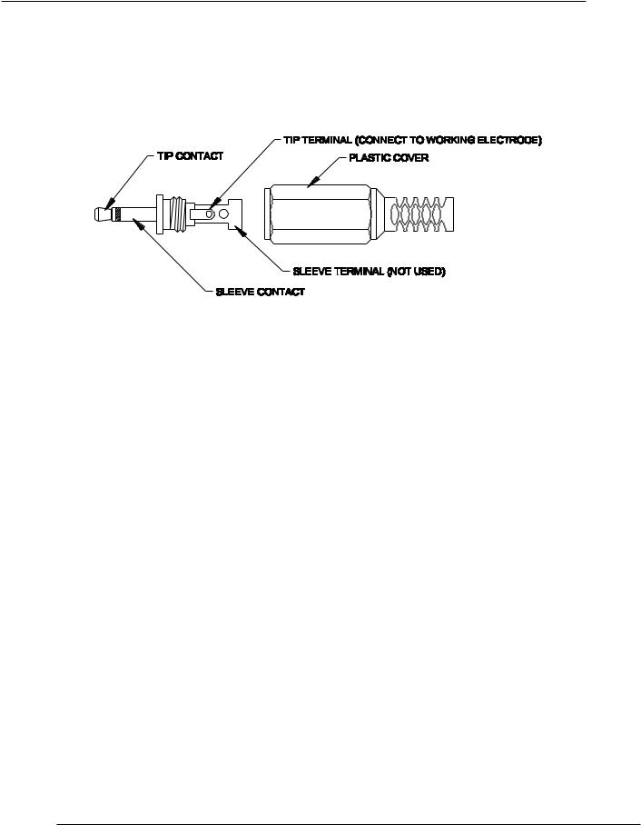
3.3.6.1Crystal Face Mating Connector
The mating connector to the Crystal Face Connector is a 2.5 mm male plug. The plug carries two contacts, the tip and the sleeve (see Figure 1). However, only the tip contact is used to connect to the working electrode of a potentiostat. You can solder the working electrode wire directly to the tip terminal. The sleeve terminal is not used. You can disregard it or break it off.
Figure 1 Crystal Face Mating Connector
3.3.7FINE AND COURSE CAPACITANCE ADJUSTMENTS
The Fine and Course capacitance adjustments are used together to cancel out the unwanted static capacitance of the crystal, the crystal holder, and the connecting cable. Refer to Section 3.4 for procedure on the proper adjustment.
OPERATION 3-3

RQCM – RESEARCH QUARTZ CRYSTAL MICROBALANCE
Figure 2 Crystal Channel Description
3-4 OPERATION

RQCM – RESEARCH QUARTZ CRYSTAL MICROBALANCE
3.4ADJUSTING THE CAPACITANCE CANCELLATION
Proper adjustment of the Capacitance Cancellation is critical in obtaining accurate results with high resistance (heavily damped) crystals. See Section 5.8. The cancellation adjustment should be performed with the crystal holder and crystal in the measurement environment. For instance, if liquid measurements are to be made, insert the crystal and its holder into the liquid where the measurement will be made.
With the crystal and holder in the measurement environment, press and hold the Reset switch. Pressing and holding the Reset switch forces the VCO to its minimum frequency, turns on the Lock LED, and turns off the quadrature current injector. Forcing the VCO to its minimum frequency insures that the crystal is being driven at a frequency far from its resonant frequency where its impedance is essentially due only to the shunt electrode capacitance. With the quadrature current injector turned off, the measured current is due only to the net shunt capacitance. The measured net shunt capacitance is the capacitance of the cable, holder and crystal electrodes minus the compensation capacitance. If the capacitance is under compensated, the phase of the measured current leads the voltage, (a phase angle of plus 90 degrees). If the capacitance is over compensated, it lags the voltage, (a phase angle of minus 90 degrees).
The Yellow Sweep LED is used to determine whether the crystal capacitance is over compensated or under compensated. The Sweep LED flashes whenever the crystal capacitance in under compensated.
If the Sweep LED is not flashing, turn the fine adjustment counterclockwise until it begins to flash then back up until it just stops. If it is flashing, turn the fine adjustment clockwise until it just stops flashing. This is a very fine adjustment. Go back and forth until you are sure you are right on the edge. The sensitivity of the fine adjustment is approximately 0.05 pfd per degree. In
situations where the crystal resistance is very high (over 1 KΩ) a net capacitance of over 0.5 pfd can result in a significant frequency error so try to get this adjustment to within a couple of degrees. Remember to keep the Reset switch depressed while making this adjustment.
3.5ADJUSTING CAPACITANCE CANCELLATION TRIMMER & SWITCH
Setting up the capacitance cancellation is fairly straightforward. The thing to remember is that there are two adjustments, a course (rotary switch) and a fine (capacitor trimmer) with the total compensation capacitance being the sum of the two. The trim capacitor has no stops so it’s not obvious when it is at its minimum or its maximum.
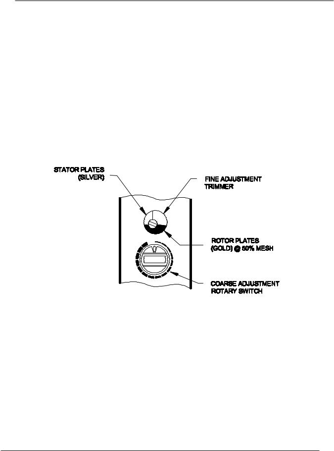
The fine adjustment capacitor has circular, rotor plates that mesh into fixed stator plates. The capacitance is at a maximum when the plates are fully meshed and a minimum when rotor plates are above the stator plates and not meshed. As the capacitor is rotated clockwise it goes through a full cycle from maximum to minimum and back to maximum. Or, depending on where you start it may go first toward a minimum, then to a maximum and then back toward a minimum. To avoid confusion, always turn the fine adjustment clockwise as we approach the desired capacitance and we want the capacitance to be decreasing.
The coarse adjustment is a rotary switch. Like the fine adjustment, it goes from its minimum to its maximum, then back to its minimum capacitance value in a full rotation. The difference is that it has 16 positive stops. Observe the “V” notch on the switch (Figure 3). The coarse adjustment is at its minimum capacitance when the “V” notch is pointing straight upward (zero position). The capacitance is increased with each stop as the switch is rotated clockwise. It reaches maximum capacitance at the 15th stop – one stop before returning to the zero position.
The RQCM is setup for a standard INFICON crystal holder and cable from the factory so you should not have to change the course adjustment. Simply connect the cable and crystal holder to
OPERATION 3-5
RQCM – RESEARCH QUARTZ CRYSTAL MICROBALANCE
the SMB connector labeled Crystal but don’t install a crystal.
If the Sweep LED is flashing, press and hold the Reset button and then turn the fine trimmer clockwise until it just stops flashing. Go back and forth a few times to get a feel for the point where the Sweep LED just stops flashing. Release the Reset button and the Sweep LED should begin to flash again.
Install a crystal. The PLO should lock. Even so, press and hold the Reset button and again adjust the fine trimmer to the point where the flashing just stops. The capacitance cancellation adjustment is now perfect. Remember to check this adjustment whenever the crystal’s environment changes.
If you could not find the proper zero capacitance point using the fine trimmer alone, then the coarse rotary switch needs to be adjusted. Follow the instructions below to set the coarse rotary switch.
First adjust the fine trimmer so that it is 50% meshed and the rotor plates are below the shaft. You can see these plates through the oversize adjustment hole. See Figure 3. Next connect a cable and crystal holder, and the crystal, if you haven’t already done so.
Figure 3 Capacitance Adjustments
Set the course rotary switch to its minimum. Depress the Reset button, and observe the yellow, Sweep, LED. It should be flashing very fast, indicating the capacitance is grossly under compensated. Now rotate the course switch clockwise, one step at a time. At each stop observe the yellow, Sweep, LED, at some point it will cease to flash. Back off one stop so the flashing begins again. The course adjustment is complete.
Slowly adjust the fine trimmer clockwise (increasing capacitance) until the flashing of the Sweep LED just stops. The capacitance compensation adjustment is now complete. Release the Reset button and assuming the crystal is not dead or out of range, the RQCM will lock on it.
3.5.1AS A GENERAL RULE
♦The Reset switch must be depressed during the adjustment for capacitance cancellation.
♦Capacitance cancellation is essential for accurate measurements of liquids and lossy (soft)
3-6 OPERATION
Loading...