


SQC-122c
Thin Film Deposition Controller
User’s Guide
Version 2.0
© Copyright Sigma Instruments, Inc. 1999 - 2002
Sigma
instruments
Safety Information
Read this manual before installing, operating, or servicing equipment. Do not install substitute parts, or perform any unauthorized modification of the product. Return the product to Sigma Instruments for service and repair to ensure that safety features are maintained.
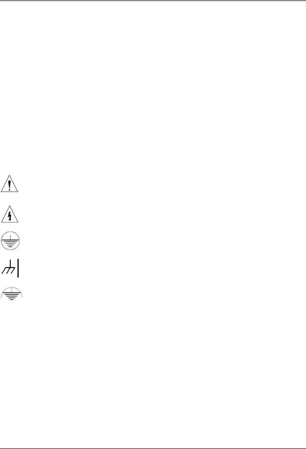
Safety Symbols
WARNING: Calls attention to a procedure, practice, or condition that could possibly cause bodily injury or death.
CAUTION: Calls attention to a procedure, practice, or condition that could possibly cause damage to equipment or permanent loss of data.
Refer to all manual Warning or Caution information before using this product to avoid personal injury or equipment damage.
Hazardous voltages may be present.
Earth ground symbol.
Chassis ground symbol.
Equipotential ground symbol.

Warranty Information
This Sigma Instruments product is warranted against defects in material and workmanship for a period of 1 year from the date of shipment, when used in accordance with the instructions in this manual. During the warranty period, Sigma Instruments will, at its option, either repair or replace products that prove to be defective.
Limitation of Warranty
Defects from, or repairs necessitated by, misuse or alteration of the product, or any cause other than defective materials or workmanship are not covered by this warranty. NO OTHER WARRANTIES ARE EXPRESSED OR IMPLIED, INCLUDING BUT NOT LIMITED TO THE IMPLIED WARRANTIES OF MERCHANTABILITY AND FITNESS FOR A PARTICULAR PURPOSE. UNDER NO CIRCUMSTANCES SHALL SIGMA INSTRUMENTS BE LIABLE FOR CONSEQUENTIAL OR OTHER DAMAGES RESULTING FROM A BREACH OF THIS LIMITED WARRANTY, OR OTHERWISE.
Return Policy
The purchaser may return this product in new condition within 30 days after shipment for any reason. In case of return, purchaser is liable and responsible for all freight charges in both directions.
Sigma Instruments
120 Commerce Drive, Unit 1 Fort Collins, CO 80524 USA 970-416-9660
970-416-9330 (fax)

Table of Contents |
|
||
Chapter 1 |
Quick Start |
|
|
1.0 |
Introduction................................................................................................ |
|
1-1 |
1.1 |
Thin Film Process Overview........................................................................ |
1-1 |
|
1.2 |
System Connections................................................................................... |
1-2 |
|
1.3 |
Front Panel................................................................................................ |
|
1-3 |
1.4 |
Rear Panel ................................................................................................ |
|
1-4 |
1.5 |
Installation ................................................................................................. |
|
1-5 |
1.6 |
Process Setup ........................................................................................... |
|
1-6 |
1.7 |
Depositing a Film ....................................................................................... |
1-8 |
|
Chapter 2 |
Operation |
|
|
2.0 |
Introduction................................................................................................ |
|
2-1 |
2.1 |
Definitions.................................................................................................. |
|
2-1 |
2.2 |
Defining a Film........................................................................................... |
|
2-1 |
2.3 |
Defining a Process ..................................................................................... |
2-5 |
|
2.4 |
Sensor Setup ............................................................................................. |
|
2-7 |
2.5 |
Source Setup ............................................................................................. |
|
2-10 |
2.6 |
Running a Process..................................................................................... |
2-11 |
|
2.7 |
Loop Tuning............................................................................................... |
|
2-15 |
2.8 |
Troubleshooting ......................................................................................... |
2-17 |
|
Chapter 3 |
Menus |
|
|
3.0 |
Introduction................................................................................................ |
|
3-1 |
3.1 |
Main Menu................................................................................................. |
|
3-2 |
3.2 |
Next Menus ............................................................................................... |
|
3-4 |
3.3 |
Quick Setup Menu...................................................................................... |
3-5 |
|
3.4 |
Process Menus .......................................................................................... |
|
3-7 |
3.5 |
Film Menus ................................................................................................ |
|
3-11 |
3.6 |
System Parameters Menu........................................................................... |
3-18 |
|
3.7 |
I/O Setup. .................................................................................................. |
|
3-21 |
Chapter 4 |
Options |
|
|
4.0 |
Introduction................................................................................................ |
4-1 |
4.1 |
Options Cards............................................................................................ |
4-1 |
4.2 |
Full Rack Extender Installation.................................................................... |
4-1 |

Appendix
A.Material Parameters
B.Specifications
C.I/O Connections
D.Handheld Remote Controller
E.Declaration of Conformity

Chapter 1 |
Quick Start |
1.0 Introduction
The SQC-122c is a multi-channel quartz crystal monitor and deposition controller. It measures up to six 1MHz to 6 MHz quartz crystal sensors, and controls two evaporation sources. Twenty-five processes, consisting of 250 layers and 25 materials, can be stored for easy retrieval. Eight process control relays, and eight digital inputs are easily configured to support a broad range of external functions, including source pocket rotation.
The SQC-122c can also be controlled via the standard RS-232 interface and Windows control program. An optional handheld remote power control is also available.
Note: The SQC-122 (color display) replaces our original (monochrome) SQC-122. Operation and programming of the two models are identical.
This chapter will aid you in the initial setup and operation of your system. Please review the entire manual for detailed operational, programming, and safety information.
1.1 Thin Film Process Overview
The SQC-122c stores the recipes, and provides the operating functions, required to control thin film deposition processes. A typical thin film deposition cycle is shown below.
The cycle can be broken into three distinct phases: pre-conditioning (ramp/soak), deposition, and post-conditioning (feed/idle). During pre-conditioning, power is supplied in steps to prepare the evaporation source for deposition. Once the material is near the desired deposition rate, material deposition begins. During deposition, the PID loop adjusts the evaporation source power as required to maintain the desired deposition rate. When the desired thickness is reached, the evaporation source is set to idle power. At this point the process may be complete, or deposition of another film layer may begin.
1-1

Chapter 1 |
Quick Start |
1.2 Front Panel
SoftKeys |
Control Knob Remote Jack |
|
Front Panel Controls |
SoftKeys |
Provide access to instrument operations and setup menus. |
|
The functions of the SoftKeys change to adapt to different |
|
operations and are displayed on the left of the screen. |
Control |
Used to adjust values and select menu items. Pushing the |
Knob |
control knob stores the current setting and moves to the next. |
Remote |
Connection jack for the optional handheld remote control |
Jack |
module. See Appendix D. |
1-2
Chapter 1 |
Quick Start |
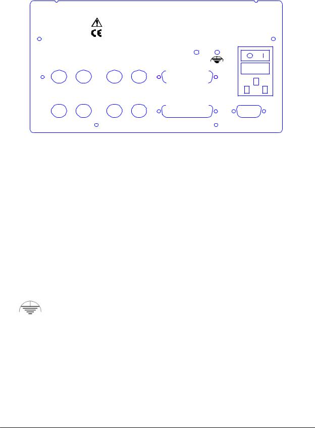
1.3 Rear Panel
Manufactured By |
SQC-122c Deposition Controller |
|
S i g m a |
||
Serial No. |
||
? instruments |
|
Sensor 3 Sensor 4 |
Output 3 Output 4 |
|
I/O 9-16 |
|
|
|
|
|
|
|
|
|
|
|
Sensor 1 Sensor 2 |
Output 1 Output 2 |
I/O 1-8 |
|
|
|
100-120/200-240 V~ |
5 0 / 6 0 H z |
25 VA |
Fuse T.5A 250V |
R S - 2 3 2
Sensor 1 & 2
Output 1 & 2
I/O (1-8)
RS-232
Sensor 3 & 4
Output 3 & 4
I/O 9-16
Rear Panel Connections
Connects to quartz crystal sensor remote oscillator.
Connects the SQC-122c output to your evaporation supply control input.
Connects 8 relays and 8 digital inputs to external equipment for process control. See Appendix C for connections.
Connects to computer for programming and data acquisition.
This option card is available only on SQC-222 controllers. Contact Sigma for upgrade information.
Measurement ground terminal useful for common system and cable grounding.
Power Input and |
WARNING: For continued protection, replace fuses with the |
Fuse |
proper type and rating. |
|
WARNING: Use removable power cords only of the specified |
|
type and rating, attached to a properly grounded receptacle. |
1-3

Chapter 1 |
Quick Start |
1.4 System Connections
S e n s o r
I n - V a c
C a b l e
F e e d t h r o u g h
6 " B N C C a b l e
Oscillator
S o u r c e Shutter
B N C |
Evaporation Supply |
C a b l e s |
|
|
O u t p u t C o n t r o l I n p u t |
|
G r o u n d W i r e |
This section identifies typical system components and their connection:
System Components
Sensor
In-Vac Cable
Feedthrough
6” BNC Cable
Oscillator
Sensor Input
BNC Cable
Control Output
BNC Cable
Ground Wire
Holds the quartz crystal used to measure rate and thickness. Crystals must be replaced occasionally.
A coaxial cable that connects the sensor to the feedthrough.
Provides isolation between vacuum and atmosphere for electrical and cooling lines.
Provides a flexible connection from the feedthrough to the oscillator. Keep this cable as short as possible.
Contains the electronics to operate the quartz crystal. Total cable length to the crystal should be under 40”.
Connects the oscillator to the SQC-122c input. Lengths up to 100’ are acceptable.
Connects the SQC-122c output to the evaporation source’s control voltage input. Keep the length below 10’.
A wire, typically braided, that connects the vacuum system to the SQC-122c ground terminal.
1-4

Chapter 1 |
Quick Start |
1.5 Installation
WARNING: Care should be exercised to route SQC-122c cables as far as practical from other cables that carry high voltages or generate noise. This includes other line voltage cables, wires to heaters that are SCR-controlled, and cables to source power supplies that may conduct high transient currents during arc down conditions.
Rack
Installation
Power
Connection
Sensor Input
Connections
Source Output
Connections
Digital I/O
Connections
Computer
Connection
The SQC-122c occupies a 5.25” high, half-rack space. An optional installation kit is available to adapt to a full rack (see Chapter 4). Install the unit in a 19” rack with the supplied hardware.
The SQC-122c automatically detects mains voltages of 100120 and 200-240VAC, 50/60Hz.
WARNING: Verify that the power cable provided is connected to a properly grounded mains receptacle.
Connect the BNC cables and oscillators from your vacuum chamber feedthrough to the desired SQC-122c sensor inputs.
Connect the BNC cables from the SQC-122c output connectors to your evaporation supply control input.
Refer to Appendix C for details on wiring digital I/O to the SQC122c Relay I/O connectors.
If you would like to use the Windows software to collect data or program the SQC-122c, attach a 9 pin straight-thru cable from the RS-232 connector to your computer’s serial port.
1-5
Chapter 1 |
Quick Start |
1.6 Process Setup
Follow these steps to build a process from the main (also called “power up”) screen.
Note: If you are prompted for a password, use the switches along the left of the screen to enter the password. The top switch is “1”, the bottom switch is “6”. If you forget the password, see the System Parameters section for password setup.
Power |
Move the rear panel power switch to the On (|) position. The |
||||||||||||||
On |
SQC-122c will briefly display its initialization information, then |
||||||||||||||
|
|
|
|
go to normal operating mode. |
|
|
|
|
|
|
|||||
Select |
Press the Quick Setup SoftKey to view the quick setup |
||||||||||||||
Quick Setup |
parameters for the current process. |
|
|
|
|
|
|
||||||||
|
|
|
|
If no Quick Setup option is visible, no processes are defined in |
|||||||||||
|
|
|
|
the SQC-122c. In that case, press Film Menu, then scroll the |
|||||||||||
|
|
|
|
cursor until an <Empty> film is selected. Press Create to |
|||||||||||
|
|
|
|
create a new film, then press Main Screen. Now press |
|||||||||||
|
|
|
|
Process Menu, then Create, then Edit. Select Insert Layer, |
|||||||||||
|
|
|
|
scroll to your new film and press Enter. Now press Prev Menu |
|||||||||||
|
|
|
|
twice to return to the Main Menu. |
|
|
|
|
|
|
|||||
|
|
|
|
|
|
|
|
||||||||
|
|
|
|
THICKNESS(kA) |
RATE(A/s) |
|
POWER(% ) |
|
|||||||
|
|
Next |
|
|
|||||||||||
|
|
|
0.000 |
|
|
0.0 |
|
|
0.0 |
|
|
|
|||
|
|
Menu |
|
|
|
|
|
|
|
|
|||||
|
|
|
100.0 |
|
|
|
|
|
|
|
|
|
|
|
|
|
|
|
|
|
|
|
|
|
|
|
|
|
|
|
|
|
|
|
|
|
|
|
|
|
|
|
|
|
|
|
|
|
|
Quick |
|
|
|
|
|
|
|
|
|
|
|
|
|
|
|
Setup |
|
|
|
|
|
|
|
|
|
|
|
|
|
|
|
|
|
50.0 |
|
|
|
|
|
|
|
|
|
|
|
|
|
|
|
|
|
|
|
|
|
|
|
|
|
||
|
|
Process |
|
|
|
|
|
|
|
|
|
|
|
|
|
|
|
|
|
|
|
|
|
|
|
|
|
|
|
||
|
|
Menu |
|
|
|
|
|
|
|
|
|
|
|
|
|
|
|
|
|
|
|
|
|
|
|
|
|
|
|
|
|
|
|
|
|
|
|
|
|
|
|
|
|
|
|
|
|
|
|
Film |
|
|
|
|
|
|
|
|
|
|
|
|
|
|
|
Menu |
|
0.0 |
|
|
|
|
|
|
|
|
|
|
|
|
|
|
|
|
|
|
|
|
|
|
|
|
|
|
|
|
|
|
|
0.0 |
12.5 |
25.0 |
37.5 |
50.0 |
|
|
|||||
|
|
System |
|
|
|
||||||||||
|
|
|
|
|
|
|
Power (% vs. Time) |
|
|
|
|
|
|
||
|
|
Params |
|
|
|
|
|
|
|
|
|
|
|
|
|
|
|
|
|
PHASE: Stopped |
|
|
|
|
|
|
|||||
|
|
|
|
Process : My Process 1 |
|
Run Time : 0:00:00 |
|
|
|
|
|||||
|
|
Start |
|
|
|
|
|
|
|||||||
|
|
|
Layer: 1 of 1 |
|
|
|
Final Thick : 0.1011 |
|
|
|
|
||||
|
|
|
|
Film : Aluminum |
|
|
|
Layer Rate : 11.1 |
|
|
|
|
|||
|
|
|
|
|
|
|
|
|
|
|
|
|
|
|
|
Main Screen
1-6

Chapter 1 |
Quick Start |
Edit Mode
Edit
Layer 1
To edit a setting in any menu, turn the control knob to scroll to the desired setting, then press the Edit SoftKey.
In Edit mode, the cursor moves to the setting value and the SoftKey functions change to show:
Next: Store the parameter and move to next parameter for editing.
Cancel: Stop editing and return the selected parameter to its previous value.
Enter: Stop editing and save values for selected parameter.
In Edit mode, adjust the control knob to set the desired parameter value.
Spend some time navigating through the Quick Setup parameters and editing values. When you are comfortable, be sure your values for Layer 1 match those shown below.
Exit to Main
Edit
Next
Layer
THICKNESS(kA) |
|
RATE(A/s) |
POWER( % ) |
|
0.000 |
0.0 |
0.0 |
|
|
My Process 1 -> Layer 1 -> |
|
|
||
Parameter |
|
Value |
Units |
|
|
|
|
|
|
Init Rate |
11.1 |
A/s |
|
|
|
||||
Fnl Thk |
0.101 |
kA |
|
|
P Term |
50 |
None |
|
|
I Term |
0.7 |
Sec. |
|
|
D Term |
0.0 |
Sec. |
|
|
Sensor 1 |
|
O n |
On/Off |
|
Sensor 2 |
|
O n |
On/Off |
|
Output |
|
Out1 |
Out1/Out2 |
|
Max. Power |
76.0 |
% |
|
|
Slew Rate |
10.0 |
% |
|
|
Material |
|
Copper |
|
|
|
|
|
||
|
|
|
|
|
Quick Setup Menu
Exit to Main |
Press Exit to Main to return to the main screen. |
1-7

Chapter 1 |
Quick Start |
1.7 Depositing a Film
If you have followed this Quick Start chapter, you are ready to deposit a film.
Note: You can simulate the steps below, without actually depositing a film, by going to the System Parameters Menu and selecting Simulate Mode ON. Simulate mode is useful for testing processes before applying power to the evaporation supply. See Section 3.6 for System Parameters Menu information.
Verify Output |
From the Main Menu, press the Next Menu SoftKey. Then, |
Operation |
press Auto/Manual to display Manual/Auto. Slowly turn the |
|
control knob to increase the control voltage to your evaporation |
|
supply. Verify that the Power(%) reading in the display upper |
|
right-hand corner approximates the actual output of your |
|
evaporation supply. If not, check your hookup (1.5), and refer |
|
to Scale Voltage (3.6). |
Verify Sensor |
Press Next Menu until the Switch Displays option is shown. |
Operation |
Press Switch Displays to display Sensor 1 and Sensor 2 in |
|
the lower status section of the screen. At least one sensor |
|
should be ON and display a % life of over 50%. If not, check |
|
your sensor connections (1.5), and refer to Min/Max Frequency |
|
(3.6). |
Enter |
Press the Next Menu key twice to display the output screen. |
Auto Mode |
Press Manual/Auto until Auto/Manual is displayed. |
Show |
Press Next Menu once more. Press the Next Graph SoftKey |
Power Graph |
until the graph shows Power (% vs. Time). |
Start |
Press the Start key to start the deposition process. Graphing |
Process |
of the output power should start. |
|
Caution: Observe the output power versus your evaporation |
|
supply’s actual output. If there is a problem, press the Stop |
|
SoftKey immediately. |
If the rate and thickness readings do not match your expectations, refer to Appendix A for information on Density and Z-Factor, and Section 2.4 for Tooling.
Please take time to review the remainder of this manual for detailed operational, programming, and safety information.
1-8

Chapter 1 |
Quick Start |
This page left blank for your notes.
1-9

Chapter 2 |
Operation |
2.0 Introduction
This chapter describes common tasks associated with operating the SQC-122c. It assumes that you understand basic operation of the menus and parameter setup as described in Chapter 1. Detailed definitions of unfamiliar setup parameters can be found under the appropriate menu description in Chapter 3.
2.1 Definitions
Several terms will be used repeatedly throughout this manual. It is important that you understand each of these terms.
Material: A physical material to be deposited. A database of approximately 100 materials is stored in the SQC-122c, and additional materials may be added using the setup software. Three parameters completely define a material: Name, Density, and Z- Factor. A table of common materials, their density, and Z-Factor is listed in Appendix A.
Film: A film describes in detail how a material will be deposited. It includes the material definition and all of the preconditioning, deposition, and post conditioning variables necessary to accurately deposit the material. Because the film definition does not include rate and thickness information, a film can be used in several different processes. The SQC-122c stores up to 25 films.
Layer: Layers are the basic building blocks of processes. A layer consists of a film and the thickness and rate that it be deposited in a process.
Process: A deposition process is a sequence of layers (i.e. films, materials) to be deposited. The SQC-122c can store up to 25 processes, consisting of a total of 250 layers.
2.2 Defining a Film
A film is a material to be deposited, plus all of its associated setup parameters. Keep in mind that a film can be used in multiple processes. Editing a film’s parameters will cause changes to every process where the film is used.
To define a film, select Film Menu on the main screen. A list of 25 films (or <Empty>) will be displayed. To define a new film, scroll to <Empty> and press Create. A new Film# is added to the list of existing films (you can use the SQC-122c setup software later to assign descriptive film names). Press Edit to display the parameters for this film.
2-1

Chapter 2 |
Operation |
The most commonly modified parameters are shown on the first film parameters screen. Additional parameters can be accessed by pressing Film Conds (film conditioning) or Deposit Controls.
|
|
|
THICKNESS(kA) |
|
RATE(A/s) |
POWER(%) |
|
|
|
Exit to |
|
|
|
||||
|
|
0.000 |
0.0 |
0.0 |
|
|
||
|
Main |
|
|
|
||||
|
|
My Process 1 Editing: Aluminum |
|
|
|
|||
|
|
|
|
|
|
|||
|
|
|
|
|
|
|||
|
Prev |
|
Parameter |
|
Value |
Units |
|
|
|
Menu |
|
|
|
|
|
|
|
|
P Term |
50 |
None |
|
|
|||
|
|
|
|
|||||
|
|
|
|
|
|
|
|
|
|
|
|
I Term |
0.7 |
Sec. |
|
|
|
|
|
|
|
|
||||
|
Edit |
|
|
|||||
|
|
D Term |
0.0 |
Sec. |
|
|
||
|
|
|
Sensor 1 |
|
On |
On/Off |
|
|
|
|
|
|
|||||
|
Film |
|
Sensor 2 |
|
On |
On/Off |
|
|
|
Conds. |
|
Film Tooling |
100 |
% |
|
|
|
|
|
|
Output |
|
Out1 |
Out1/Out2 |
|
|
|
|
|
|
|
|
|||
|
Deposit |
|
|
|||||
|
|
1 |
|
|
|
|||
|
Controls |
|
|
|
|
|||
|
|
Max Power |
76.0 |
|
|
|
||
|
|
|
|
|
|
|||
|
|
|
|
|
|
|||
|
|
|
Slew Rate |
10.0 |
% |
|
|
|
|
|
|
Crystal Quality |
|
Disabled |
|
|
|
|
|
|
|
|
|
|
||
|
|
|
|
|
|
|
|
|
|
|
|
|
|
|
|
|
|
Film Edit Menu
Scroll to the end of the list (Z-Factor), then scroll back up to Material. Press Edit to scroll through the list of available materials. Notice that the Density and Z-Factor are updated automatically as a new material appears.
Select the desired material and press Enter. You could change the Density and Z- Factor for the selected material now, but it is unlikely those values are wrong. To add a material name that is not listed, you must use the SQC-122c setup software.
Once the material is selected, set up the source parameters. Scroll to Output and select the SQC-122c rear panel output that is connected to the source evaporation supply. If a source pocket indexer is being used, assign it also.
Now assign the Max Power and Slew Rate appropriate for this material and your power supply. For now, set both to 100%. Set them to lower values later if you find that small power changes cause excessively large changes in deposition rate.
The SQC-122c can use multiple sensors to measure a film’s deposition rate and thickness. If multiple sensors are selected, an average of the sensors is used. Set each sensor that will be used to measure this film to ON. Alternately, you might want to use a dual shuttered sensor in case of crystal failures. See the Film Menu section of Chapter 3 for instructions on setting up a primary/secondary dual sensor.
2-2

Chapter 2 |
Operation |
The PID parameters control the response of the SQC-122c to changes in deposition rate. These values are unique to each deposition chamber setup, and to a lesser extent to each material.
The P Term is proportional (or gain), the % process rate change divided by the % input power change. The I Term (integral) sums the rate deviations over time to more accurately achieve the rate setpoint. The D Term (derivative) speeds response to sudden changes in rate. Volumes have been written on determining the proper PID settings. See the section on Loop Tuning later in this chapter for a common PID loop tuning procedure. For now, you should probably leave these values at their defaults.
Press Film Conds to enter the film conditioning menu. Film preconditioning is used to prepare a material for deposition. When the film deposition is complete, post conditioning ramps power down to an idle level. It may also ramp power to a level appropriate for wire feeding new material. Refer to the Thin Film Process Overview in Chapter 1 for an illustration of pre and post conditioning.
|
|
|
THICKNESS(kA) |
|
RATE(A/s) |
POWER(%) |
|
|
|
Exit to |
|
|
|
||||
|
|
0.000 |
0.0 |
0.0 |
|
|
||
|
Main |
|
|
|
||||
|
|
My Process 1 Editing: Aluminum |
|
|
|
|||
|
|
|
|
|
|
|||
|
|
|
|
|
|
|||
|
Prev |
|
Parameter |
|
Value |
Units |
|
|
|
Menu |
|
|
|
|
|
|
|
|
Ramp1 Power |
50 |
% |
|
|
|||
|
|
|
|
|
|
|
|
|
|
|
|
Ramp1 Time |
0.7 |
h:mm:ss |
|
|
|
|
Edit |
|
|
|||||
|
|
Soak1 Time |
0.0 |
h:mm:ss |
|
|
||
|
|
|
Ramp2 Power |
|
O n |
% |
|
|
|
|
|
|
|||||
|
|
|
Ramp2 Time |
|
O n |
h:mm:ss |
|
|
|
|
|
Soak2 Time |
|
Out1 |
h:mm:ss |
|
|
|
|
|
Feed Power |
75.0 |
% |
|
|
|
|
|
|
Ramp Time |
10.0 |
h:mm:ss |
|
|
|
|
|
|
Feed Time |
0:00:00 |
h:mm:ss |
|
|
|
|
|
|
Idle Power |
2.90 |
% |
|
|
|
|
|
|
Ramp Time |
0.950 |
h:mm:ss |
|
|
|
|
|
|
|
|
||||
|
|
|
|
|
|
|
|
|
|
|
|
|
|
|
|
|
|
Film Conditioning Menu
Set the Ramp 1 Power and Time to values that will slowly bring the material to a near molten state. Set the Soak 1 Time to a value that will allow the material to homogeneously achieve the state. Ramp 2 is used to slowly bring the material to a power level that nearly matches the desired deposition power. Use Soak 2 to hold the material at that level until deposition (i.e. rate control) begins.
If you use wire feed to replenish material after deposition, set the Feed Power and times as required. Idle typically ramps output power back toward zero at the end of a process.
2-3

Chapter 2 |
Operation |
From the Film Conds menu, press Prev Menu to return to the main Film Params menu. Now press Deposit Controls. The Deposit Controls menu contains parameters that modify operation during the deposition phase.
Exit to Main
Prev
Menu
Edit
THICKNESS(kA) |
|
RATE(A/s) |
|
POWER(%) |
|
0.000 |
0.0 |
0.0 |
|
||
Current: Process 1 |
|
EDITING: |
Film 1 |
||
|
|
|
|
|
|
Parameter |
|
Value |
|
Units |
|
|
|
|
|
|
|
|
|
|
|
h:mm:ss |
|
Shutter Delay |
0:01:00 |
|
|
||
|
|||||
|
|
|
|
|
|
Capture |
20.0 |
% |
|
||
Control Error |
|
(Ignore, Stop, Hold) |
|
|
|
Setting |
|
Hold |
|
|
|
Error |
18.0 |
% |
|
||
Rate Sampling |
|
(Cont,Time,Acc based) |
|
||
Setting |
|
Undefined |
|
|
|
Accuracy Based |
0.0 |
% |
|
||
|
|
|
|
|
|
|
|
|
|
|
|
Deposition Controls Menu
Shutter delay causes the SQC-122c to delay opening the shutter until the process has stabilized at the desired deposition rate. The time value is the maximum amount of time to wait, before an error is sensed. Capture is the % rate deviation that must be achieved to open the shutter and go to the Deposit phase. Capture will override the shutter delay if accuracy is reached. Set Shutter Delay and Capture to zero to disable this feature.
If the SQC-122c is unable to maintain the desired deposition rate (for example, out of material or a bad sensor), one of three actions is possible. Keep trying (Ignore), set power to zero to halt deposition (Stop), or maintain constant power (Hold) and extrapolate thickness from the last good rate reading. Until your process is known and stable, it is best to leave the Control Error setting on Ignore.
Rate sampling can extend sensor life in high rate processes. Select Cont (continuous) to disable rate sampling. A Time selection closes the shutter for a fixed time, then opens the shutter for a fixed time to sample the rate. Acc Based (accuracy based) sampling closes the shutter for a fixed time, then opens the shutter until the desired rate is achieved. Rate Sampling assumes a very stable process!
Each film parameter has been set. Press Exit to Main to return to the Main Screen.
2-4

Chapter 2 |
Operation |
2.3 Defining a Process
A process is a sequence of film layers deposited to achieve a particular thin film characteristic. A few processes, each consisting of a few layers, may be adequate for a production facility. For research or laboratory use, the SQC-122c can store up to 25 processes to a total of 250 layers.
You should define each of the films that will make up the layers of the process before starting process definition. See the previous section for instructions on defining films.
To define a process, select Process Menu on the main screen. A list of 25 processes (or <Empty>) will be displayed. To define a new process, scroll to <Empty> and press Create. A new Process# is added to the list of existing processes (use the SQC-122c setup software to assign descriptive process names). Press Select, then Edit to display the sequence of layers and films that comprise the selected process.
To add a layer, scroll to the desired location in the layer sequence, and press Insert Layer. Select a film for this layer from the list and press Enter. Once a film is assigned to a process layer, you cannot change the film. Instead, cut the layer, then insert a new layer and select the desired film. To edit a layer, highlight it, then press Edit.
|
|
|
THICKNESS(kA) |
|
RATE(A/s) |
POWER(%) |
|
||
|
Exit to |
|
|
|
|||||
|
|
0.000 |
|
0.0 |
0.0 |
|
|
||
|
Main |
|
|
|
|
||||
|
|
My Process 1 |
Layer 1 -> |
|
|
|
|||
|
|
|
|
|
|
||||
|
|
|
|
|
|
||||
|
Prev |
|
Parameter |
|
|
Value |
Units |
|
|
|
Menu |
|
|
|
|
|
|
|
|
|
Init. Rate |
|
5.0 |
A/s |
|
|
|||
|
|
|
|
|
|||||
|
|
|
|
|
0.500 |
|
|
|
|
|
|
|
Fnl Thk |
|
kA |
|
|
||
|
|
|
|
|
|
||||
|
Edit |
|
|
|
|||||
|
|
Time Setpoint |
|
0:01:00 |
h:mm:ss |
|
|
||
|
|
|
Thickness Limit |
|
0.400 |
kA |
|
|
|
|
|
|
|
|
|||||
|
|
|
Start Mode |
|
|
Auto |
Man/Auto |
|
|
|
|
|
Ramp1 |
|
|
Enabled |
En/Dis |
|
|
|
|
|
Start Thickness |
|
0.150 |
kA |
|
|
|
|
|
|
Ramp Time |
|
0:00:30 |
h:mm:ss |
|
|
|
|
|
|
New Rate |
|
3.5 |
A/s |
|
|
|
|
|
|
Ramp2 |
|
|
Disabled |
En/Dis |
|
|
|
|
|
|
|
|
|
|
|
|
|
|
|
|
|
|
|
|
|
|
|
|
|
|
|
|
|
|
|
|
Layer Edit Menu
Remember that most setup parameters are set in the Films Menu, and apply to every instance where the film is used. The layer parameters pertain only to this instance of the film, in this process.
2-5

Chapter 2 |
Operation |
Initial Rate and Final Thickness are the main process setpoints for this layer of material. Keep in mind that the SQC-122c zeroes thickness at the beginning of each layer. It is not a cumulative value.
Time Setpoint and Thickness Limit are arbitrary values that will activate a relay when they are reached.
Start mode allows you to have this layer start immediately on completion of the previous layer, Auto mode. Manual mode waits for a user signal via the front panel, RS-232, or digital input to start the layer.
Rate Ramps allow the deposition rate to change over time, under PID control. Each rate ramp has a starting thickness, an elapsed time to ramp to the new rate, and a new rate setpoint. Each process layer can have up to two rate ramps.
Press Prev Menu to return to the list of layers, or Exit to Main to return to the Main Screen.
2-6
 Loading...