


 Loading...
O P E R A T I N G M A N U A L
Vortex® Dual
Refrigerant Recovery Machine
English· Español·Français·Deutsch·Italiano·Nederlands·Svenska·

Vortex Dual Operating Manual
Table Of Contents
English
Vortex Dual Operating Manual . . . . . . . . . . . . . . . . . . . . . . . . 3
Español
Manual de funcionamiento de Vortex Dual . . . . . . . . . . . . . 18
Français
Manuel d’utilisation Vortex Dual . . . . . . . . . . . . . . . . . . . . . 35
Deutsch
Vortex Dual Betriebsanleitung . . . . . . . . . . . . . . . . . . . . . . . 52
Italiano
Manuale Operativo Vortex Dual . . . . . . . . . . . . . . . . . . . . . . 69
Nederlands
Bedieningshandleiding voor Vortex Dual . . . . . . . . . . . . . . 86
Svenska
Användarhandbok för Vortex Dual. . . . . . . . . . . . . . . . . . . 103
Vortex Dual . . . . . . . . . . . . . . . . . . . . . . . . . . . . . . 119
2

Vortex Dual Operating Manual
Table Of Contents
Safety First!. . . . . . . . . . . . . . . . . . . . . . . . . . . . . . . . . . . . 4
Product Safety . . . . . . . . . . . . . . . . . . . . . . . . . . . . . . . . . 4
Responsibility . . . . . . . . . . . . . . . . . . . . . . . . . . . . . . . . . . 4
Trademarks. . . . . . . . . . . . . . . . . . . . . . . . . . . . . . . . . . . . 4
EPA Certification. . . . . . . . . . . . . . . . . . . . . . . . . . . . . . . . 5
Declaration of Conformity . . . . . . . . . . . . . . . . . . . . . . . . . 5
1.0 Safety Precautions . . . . . . . . . . . . . . . . . . . . . . . . . . . . . 6
2.0 Specifications, Features and Warranty. . . . . . . . . . . . . 7
2.1 Vortex Dual Specifications . . . . . . . . . . . . . . . . . . . . . . . . 7
2.2 Warranty . . . . . . . . . . . . . . . . . . . . . . . . . . . . . . . . . . . . . . 8
3.0 Setup and Operation. . . . . . . . . . . . . . . . . . . . . . . . . . . . 8
3.1 Getting Started . . . . . . . . . . . . . . . . . . . . . . . . . . . . . . . . . 8
3.2 Standard Recovery Operation . . . . . . . . . . . . . . . . . . . . 10
3.3 Purging Vortex Dual . . . . . . . . . . . . . . . . . . . . . . . . . . . . 11
3.4 Push-Pull Operation . . . . . . . . . . . . . . . . . . . . . . . . . . . . 12
3.5 Cooling The Recovery Tank . . . . . . . . . . . . . . . . . . . . . . 13
3.6 Special Operating Notes . . . . . . . . . . . . . . . . . . . . . . . . . 14
4.0 Maintenance . . . . . . . . . . . . . . . . . . . . . . . . . . . . . . . . . 14 5.0 Troubleshooting . . . . . . . . . . . . . . . . . . . . . . . . . . . . . . 14 6.0 Service . . . . . . . . . . . . . . . . . . . . . . . . . . . . . . . . . . . . . . 15 7.0 EPA Requirements (PN 714-202-G1 only). . . . . . . . . . 16
English
3

English
Vortex Dual Operating Manual
Thank you for buying the INFICON Vortex® Dual Refrigerant Recovery Machine! For optimal Vortex Dual performance, read this manual carefully before use.
For additional questions or assistance, contact INFICON. USA: +1.800.344.3304 or service.tools@inficon.com
Europe: +49 221 56788-660 or servicetools.europe@inficon.com
Safety First!
 This symbol is intended to alert the presence of critical items regarding operating, safety and maintenance (servicing) instructions in this manual.
Product Safety
Vortex Dual is a recovery machine for a broad range of refrigerants. Recovering refrigerants into separate storage tanks involves a process of gas compression, resulting in high pressures within the machine, the connecting hoses, and the storage tank.
 High pressure systems can cause accident or injury if not handled properly, and with care.
Refrigerant hoses must have shut-off devices within 30.5 cm (12 in.) of the ends, to reduce the likelihood of refrigerant leakage to the atmosphere when changing tanks or setups.
Responsibility
 Do not use Vortex Dual unless properly trained in the recovery process. Operation of this machine by unqualified personnel is potentially dangerous.
Trademarks
The trademarks of the products mentioned in this manual are held by the companies that produce them.
Vortex®, Compass®, D-TEK® Select, TEK-Mate®, and Wey-TEK™ are trademarks of INFICON.
All other brand and product names are trademarks or registered trademarks of their respective companies.
The information contained in this manual is believed to be accurate and reliable. However, INFICON assumes no responsibility for its use and shall not be liable for any special, incidental, or consequential damages related to the use of this product.
© 2016 All rights reserved.
Reproduction or adaptation of any part of this manual without permission is unlawful.
4

Vortex Dual Operating Manual
EPA Certification
INFICON Vortex Dual (PN 714-202-G1 only) is an EPA Certified machine in accordance with Section 608 of the Clean Air Act. It has been independently tested and certified to conform with AHRI standard 740.
EU Declaration of Conformity
This declaration is issued under the sole responsibility of the manufacturer INFICON. The object of the declaration is to certify that this equipment, designed and manufactured by INFICON, is in conformity with the relevant Community harmonization legislation. It has been constructed in accordance with good engineering practice in safety matters in force in the Community and does not endanger the safety of persons, domestic animals or property when properly installed and maintained and used in applications for which it was made.
Equipment Description . . . . . . . . . . . . . . . . Vortex Dual Refrigerant Recovery Machine
Model Number. . . . . . . . . . . . . . . . . . . . . . . . . .714-202-Gxx
(Applicable to all Group numbers)
Applicable Directives . . . . . . . . . . . . . . . . . 2014/35/EU (LVD) 2014/30/EU (EMC) 2011/65/EU (RoHS)
Applicable Standards . . . . . . . . . . . . . . . . . EN 60335-1:2012/A11:2014 EN 55014-1:2006/A2:2011 / CISPR14-1:2005/A2:2011 EN 50581:2013
CE Implementation Date . . . . . . . . . . . . . . . April 20, 2016
English
Manufacturer Representative |
EU Authorized Representative |
Brian King |
INFICON GmbH |
INFICON |
50968 Köln, Bonner Str. 498 |
Business Line Manager – Service Tools |
|
Two Technology Place |
|
East Syracuse, NY USA 13057 |
|
Any questions relative to this declaration or to the safety of INFICON's products should be directed, in writing to the quality assurance department at the above address.
5
English
Vortex Dual Operating Manual
1.0 Safety Precautions
Read this manual before using Vortex Dual to become familiar with its specifications and operation. Review the Material Safety Data Sheets (MSDS) and the Temperature - Vapor Pressure information for the proper safety and handling requirements regarding the refrigerants being recovered.
 Wear gloves, eye protection and foot protection when working on refrigeration systems.
Refrigerant vapor can be hazardous and its by products can be lethal.
 Motors and switches can generate sparks and can be especially dangerous in flammable environments. Work only in well-ventilated areas, with mechanical ventilation that provides at least four air change rates per hour. Do not work in an enclosed area without appropriate safety equipment. It may be necessary to install a separate circulation fan.
 Never use oxygen for leak detection. Oxygen can become an explosive mixture in the presence of oil and pressure. Perform leak detection in accordance with recommended practice only. For best results, use a refrigerant detector, such as INFICON D-TEK Select, Compass, or TEK-Mate.
 Never mix refrigerants. Use separate storage cylinders, hoses, and filters for each type of refrigerant recovered. Store refrigerants in a cool,
dry place.
Never overfill a storage container. Overfilled tanks can rupture and explode.
Use a refrigerant scale such as INFICON Wey-TEK to prevent overfill.
 When opening service or cylinder valves, do so slowly, to ensure all connections are secure and free of danger.
Disconnect power before moving or servicing Vortex Dual.
 The risk of electric shock and exposure to hot compressor parts is possible if the Vortex Dual covers are removed. Vortex Dual should only be opened by a qualified technician who has been trained in basic electronics
and refrigeration.
 Use only the power cord supplied by INFICON. If the cord is lost or damaged, contact INFICON for information on obtaining a replacement.
6

Vortex Dual Operating Manual
 When connected to Vortex Dual, extension cord wiring can overheat under conditions of high current draw. If an extension cord is necessary, use the shortest
possible length and only size 14 AWG or larger for 115 V (ac) or 1.00 mm2 or larger for 230 V (ac).
 Do not use Vortex Dual near open containers of gasoline or other flammable liquids.
 This product is designed for use with refrigerants only and is not intended for use with any combustible refrigerants. Any other uses of this product are not recommended by INFICON and could result in personal injury. Use of this product other than intended is done at the user's own risk.
English
2.0Specifications, Features and Warranty
2.1Vortex Dual Specifications
Refrigerants . . . . . . . . . . . R-12, R-1234yf, R-134a, R-22, R-401A, R-401B, R-401C, R-402A, R-402B, R-404A, R-407A, R-407B, R-407C, R-408A, R-409A, R-410A, R-500, R-502, R-507
Power. . . . . . . . . . . . . . . . . 115 V (ac), 60 Hz, 12 A,
or 230 V (ac), 50/60 Hz, 10A (depending on version)
Protection . . . . . . . . . . . . . High pressure switch cutoff at 550 PSI, 3.8 MPa, 38 bar Compressor motor thermally protected
Pressure . . . . . . . . . . . . . . Low side design pressure 350 PSI, 2.4 MPa, 24 bar High side design pressure 550 PSI, 3.8 MPa, 38 bar
Temperature . . . . . . . . . . . Operating range 10 to 40°C (50 to 104°F)
Pollution degree . . . . . . . . 2 Ingress protection . . . . . . IP20
EPA Certification
(PN 714-202-G1 only) . . . . Certified for all refrigerants listed under categories III, IV, & V in ARI standard 740-1998
7

English
Vortex Dual Operating Manual
2.2 Warranty
INFICON warrants the Vortex Dual Refrigerant Recovery Machine to be free from defects of materials or workmanship for three years from the date of purchase. INFICON does not warrant any machine that has been subjected to misuse, negligence, or accident, or has been repaired or altered by anyone other than INFICON.
The compressor is warranted for a period of three years by the manufacturer. To keep this warranty in force, a filter (included) must be used on the inlet port or hose at all times to prevent particulates from entering the compressor. Failure to use the included filter will void the compressor warranty.
INFICON liability is limited to repairing or replacing, at its option, a defective machine or part. If a defect arises, a valid claim must be received by INFICON, with transportation prepaid, no later than thirty (30) days after the warranty period expires. INFICON will determine whether the machine has malfunctioned due to defective materials or workmanship.
This warranty is in lieu of all other warranties, expressed or implied, whether of merchantability, fitness for a particular purpose, or otherwise. All such other warranties are expressly disclaimed.
INFICON shall have no liability in excess of the price paid to INFICON for Vortex Dual, plus return transportation charges prepaid. INFICON shall have no liability for any incidental or consequential damages. All such liabilities are excluded.
3.0Setup and Operation
3.1Getting Started
Review the full contents of this manual before operating Vortex Dual.
 Failure to follow proper safety precautions can result in personal injury or death. Do not use Vortex Dual unless properly trained in the recovery process.
1Install the included filter on the inlet. Vortex Dual has a female refrigerant flare fitting, and connects with male flare fittings.
2Attach the hoses to the filter.
 Do not use an adapter fitting in place of a filter. Use of an adapter fitting can damage the valves and will void the warranty.
3Attach a hose from the discharge valve to the recovery tank. Connect other hoses between system components, according to Figure 1 on page 10.
8

|
Vortex Dual Operating Manual |
|
|
|
|
|
|
4 Connect the AC power cord to a circuit protected by an appropriately |
|
|
|
|
|
||
sized circuit breaker. If an extension cord is absolutely necessary, make |
|
|
|
sure it meets the following conditions: |
|
English |
|
|
contains a safety ground wire |
|
|
|
length is not excessive |
|
|
wire size 14 AWG or larger for 115 V (ac) or 1.0 mm2 or larger for |
|
|
|
|
230 V (ac) |
|
|
|
|
|
|
 Overfilled tanks can rupture and explode. When operating in standard recovery or push-pull mode, it is possible to overfill the tank. Use a refrigerant scale to ensure that the tank does not exceed 80% of its capacity, by weight. Check the tank weight before transporting.
Do not allow Vortex Dual to recover large amounts of liquid too quickly.
NOTE: When a significant amount of liquid is present and enters the recovery machine too quickly during the refrigerant recovery process, this is sometimes referred to in the field as a "liquid slug" or "slugging."
A liquid slug can activate the High Pressure shutoff and prolong the refrigerant recovery process. If Vortex Dual recovers large amounts of liquid too quickly (or a liquid slug is present), a loud knocking will sound from the compressor.
 Compressor damage caused by recovering a large amount of liquid too quickly is not covered by the compressor warranty.
Monitor the recovery process carefully. If the compressor begins to knock:
throttle the INLET valve clockwise, or
adjust the MANIFOLD gauge valves until the knocking stops.
9
Vortex Dual Operating Manual
|
3.2 Standard Recovery Operation |
|
|
||
English |
1 Connect all cables and hoses as described in section 3.1. |
|
NOTE: Make sure all connections are tight, and that the cables and |
||
|
||
|
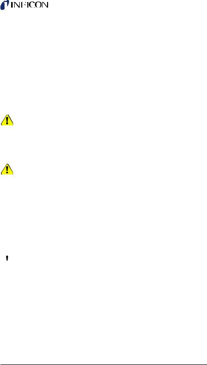
hoses do not interfere with recovery process. See Figure 1. |
|
|
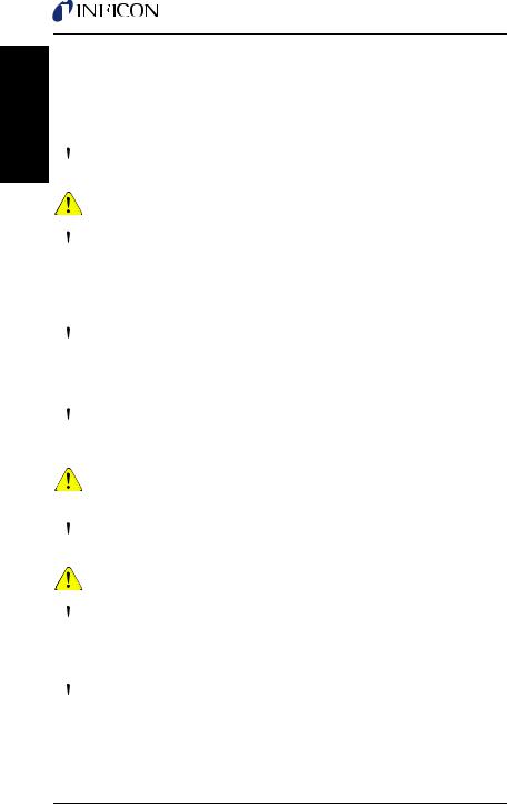
Figure 1 Setup procedure for standard refrigerant recovery |
|
|
|
VAPOR |
|
|
|
HP |
|
LP |
THROTTLE TO PREVENT |
|
System |
||
|
|
|||
|
|
|
||
LIQUID ENTERING PUMP |
|
|
|
|
|
|
CYLINDER/ |
MANIFOLD |
AC |
|
|
|
||
|
|
TANK |
|
HP |
OPEN |
PURGE |
PURGE |
|
|
|
|
|||
FILTER |
|
SCALE |
LIQUID |
|
|
|
|||
2Make sure the hose connecting Vortex Dual to the recovery tank is attached to the LIQUID port (LP).
3OPEN the LP valve on the tank. Keep the VAPOR port CLOSED.
4Rotate the INLET valve (V1) to CLOSE.
5Set the PURGE/RECOVER valve (V2) to the RECOVER position.
6Slowly rotate the LIQUID valve on the MANIFOLD gauge set to OPEN. Make sure there are no leaks.
7Turn on Vortex Dual.
8Monitor the inlet pressure (LP, Low Pressure gauge) and slowly rotate the INLET valve (V1) to OPEN.
 The compressor may emit a knocking sound if Vortex Dual attempts to recover a significant amount of liquid. To prevent damage to the compressor, throttle the LIQUID valve on the MANIFOLD gauge set, or the Vortex Dual INLET valve (V1).
9Once the liquid has been recovered, transfer the remaining vapor; rotate the INLET valve (V1) to OPEN. Make sure the LIQUID and VAPOR valves on the MANIFOLD gauge are OPEN.
10
|
Vortex Dual Operating Manual |
|
|
|
|
|
|
10 |
Continue to operate until the LP guage indicates the required vacuum has |
|
|
|
|
||
|
been obtained. |
|
|
11 |
Turn off Vortex Dual and close the INLET valve (V1). Wait five minutes. |
|
English |
|
If the MANIFOLD gauge indicates pressure has risen above 0 PSIG |
|
|
|
|
|
|
|
(0 bar), refrigerant is still present. |
|
|
|
Open the INLET valve (V1) and turn on Vortex Dual. |
|
|
|
Run Vortex Dual until the required vacuum is reached again. |
|
|
|
|
|
|
|
Wait five minutes. Repeat this process until all refrigerant |
|
|
|
is removed and pressure is 0 PSIG (0 bar), or less. |
|
|
12 |
Immediately purge Vortex Dual. Purging is necessary to remove any |
|
|
|
residual refrigerant from inside Vortex Dual internal components as well |
|
|
|
as the hose from the outlet to the recovery tank. See section 3.3. |
|
|
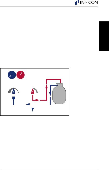
3.3 Purging Vortex Dual
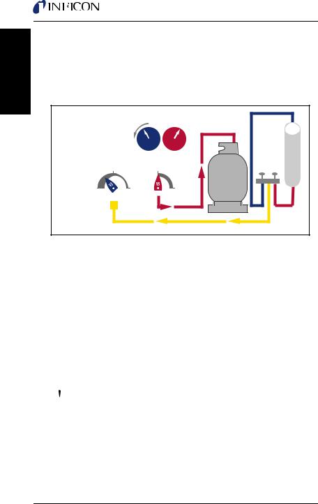
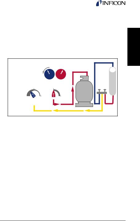
1While Vortex Dual is off, rotate the PURGE/RECOVER valve (V2) to PURGE. See Figure 2.
2Turn on Vortex Dual and slowly rotate the INLET valve (V1) to PURGE.
3Run Vortex Dual and monitor the LP gauge until a vacuum of 20 In/Hg (0.7 bar) or more is achieved.
4Turn off Vortex Dual and immediately close the valves on the recovery tank. Rotate the inlet valve (V1) to CLOSE.
 The hose and the discharge port will contain a small amount of pressurized refrigerant. Exercise care when removing this hose.
Figure 2 Setup procedure for purging
LIQUID
LP |
HP |
|
CLOSE |
RECOVER |
CYLINDER/ |
|
|
|
OPEN |
PURGE |
TANK |
PURGE |
SCALE
11
English
Vortex Dual Operating Manual
3.4 Push-Pull Operation
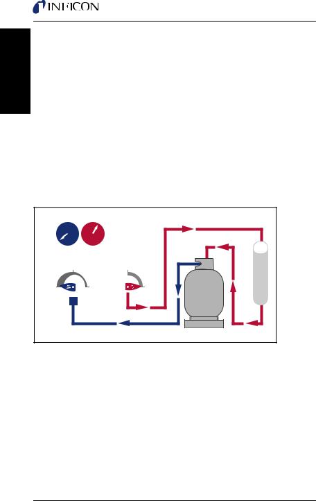
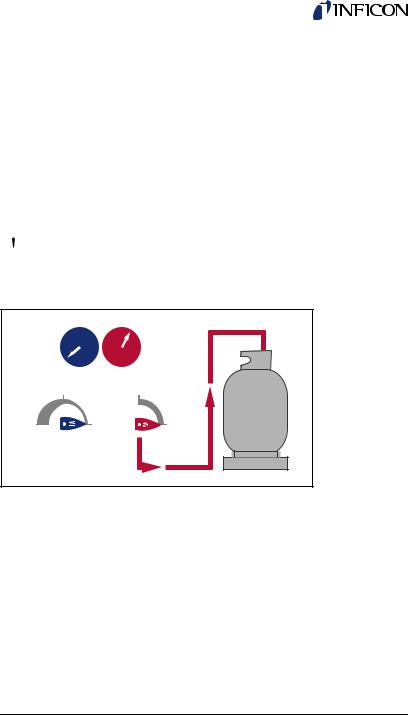
The push-pull recovery method is used to move large amounts of liquid refrigerant. During this process, the recovery unit pulls vapor from the recovery cylinder and produces high pressure discharge gas that pushes liquid out of the HVAC system and back into the recovery cylinder. Recovery rates above 15 pounds per minute can be achieved when using this procedure.
NOTE: Do not attempt the push-pull process unless the system contains at least 15 pounds (7 Kg) of liquid that can easily be isolated.
To prevent overfill, use the scale to make sure the tank does not surpass 80% capacity, by weight. Monitor the tank weight carefully as 80% capacity maybe reached quickly during push-pull due to its rapid transfer.
Connect the refrigerant hoses (see Figure 3). A sight glass, not included, can help determine when the liquid has been transferred and vapor remains.
Figure 3 Setup procedure for push-pull method |
|
|||
LP |
HP |
|
|
|
|
|
|
VAPOR |
LP |
CLOSE |
|
RECOVER |
|
|
OPEN |
PURGE |
PURGE |
CYLINDER/ |
|
FILTER |
|
|
TANK |
HP |
|
|
|
||
|
|
|
SCALE |
|
|
|
|
|
LIQUID |
12
Vortex Dual Operating Manual
3.5 Cooling The Recovery Tank
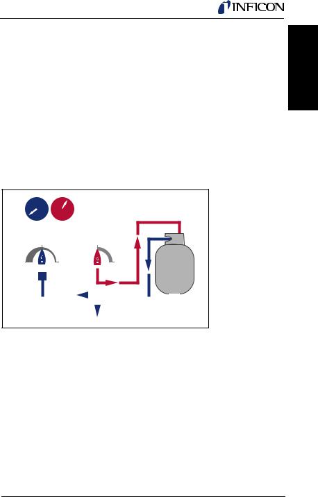
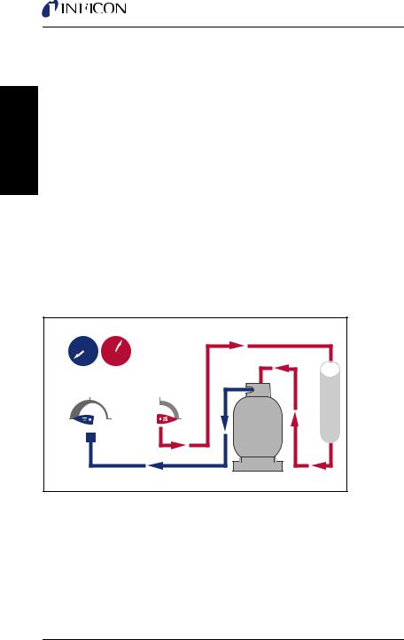
Vortex Dual can be used to pre-cool (or sub-cool) the recovery tank, if the head pressure is too high to complete the recovery process. If the ambient pressure is too high, high head pressure can occur when working with certain refrigerants that have a high vapor pressure.
NOTE: The recovery tank must contain five pounds or more of liquid, to allow the pressure differential to develop.
Sub-cooling the tank before starting the recovery process may provide little or no benefit.
If the recovery process stalls because of high head pressure, turn off Vortex Dual, close the hose valves, and reconfigure the setup as shown in Figure 4.
English
Figure 4 Setup procedure for sub-cooling method
|
|
|
LIQUID |
CLOSE |
|
RECOVER |
|
OPEN |
PURGE |
PURGE |
CYLINDER/ |
FILTER |
|
|
TANK |
|
|
|
|
|
|
|
|
|
|
|
VAPOR |
|
|
|
|
|
SCALE |
|
|
|
|
|
|
|
|
|
OPTIONAL CONNECTION TO SYSTEM
1Rotate V2 on the Vortex Dual to RECOVER and open the LIQUID and VAPOR valves on the cylinder.
2Turn on Vortex Dual.
3Rotate V1 on Vortex Dual to OPEN.
4On the cylinder, throttle the flow of liquid by slowly closing the LIQUID valve to achieve a minimum pressure differential of 100 PSIG (0.7 MPa, 7 bar) between the LP and the HP gauges.
NOTE: To prevent the HP cutoff switch from actuating,
do not allow the HP gauge to exceed 550 PSIG (3.8 MPa, 38 bar).
5Once the recovery tank is cold, turn off Vortex Dual and reconfigure the setup for standard recovery. Repeat as needed.
13

English
Vortex Dual Operating Manual
3.6 Special Operating Notes
During standard operation, the High Pressure switch will reset when the head pressure drops below approximately 425 PSI (2.9 MPa, 29 bar), and
Vortex Dual will restart automatically.
4.0 Maintenance
With minimal but important maintenance, Vortex Dual can provide many seasons of reliable service. After each use, clean Vortex Dual with a damp cloth to remove dirt and oils.
 Do not use gasoline or other hazardous solvents to clean Vortex Dual; this can damage the plastic enclosure. Standard household detergent or isopropyl alcohol may be used, but do not allow liquid to penetrate the outer case.
Make sure the inlet and discharge ports are protected during transit and storage; keep the inner diameter and the outer threads clear and clean.
NOTE: For best results, leave the filter connected to the inlet port, and change the filter regularly.
5.0 Troubleshooting
PROBLEM |
CAUSE |
ACTION |
||
Vortex Dual will not |
1. Power cord is not |
1. |
Attach power cord |
|
turn on; compressor |
attached |
2. |
Verify voltage at job site |
|
does not start |
2. No voltage at |
|||
3. Identify cause of breaker |
||||
|
||||
|
receptacle |
|||
|
activation, rectify and reset |
|||
|
3. Circuit breaker has |
|||
|
4. |
Reduce pressure; |
||
|
opened |
|||
|
rotate V2 to Purge, then |
|||
|
|
|||
|
4. Discharge pressure is |
back to Recovery |
||
|
too high; HP switch has |
5. |
Factory service required |
|
|
opened |
|||
|
|
|
||
|
5. Electronics failure in |
|
|
|
|
motor |
|
|
|
|
|
|
|
|
Compressor starts, |
1. Recovery tank valve |
1. |
Open tank valve |
|
but falters within |
is not open |
2. |
Check and clear |
|
minutes; pressure |
|
|||
2. Discharge hose |
blockage |
|||
indication on HP |
||||
blocked |
3. |
Bleed air from |
||
gauge is high |
||||
|
||||
3. Air in system/tank |
system/tank |
|||
|
||||
|
|
|
|
|
|
|
|
|
|
14

|
|
Vortex Dual Operating Manual |
|
|
|
||
|
|
|
|
|
|
|
|
|
|
|
|
|
|
|
|
|
PROBLEM |
CAUSE |
ACTION |
|
|
|
|
|
|
|
|
|
|
|
|
|
Compressor stops |
1. Vapor pressure of |
1. |
Reduce tank |
|
|
English |
|
intermittently |
refrigerant in tank is |
temperature |
|
|
||
|
|
2. Thermal overload |
being pumped; let machine |
|
|
||
|
|
close to HP trip point |
2. |
Reduce amount of liquid |
|
|
|
|
|
|
|
|
|
||
|
|
switch in compressor is |
cool before proceeding |
|
|
|
|
|
|
activating |
|
|
|
|
|
|
|
|
|
|
|
|
|
|
Vortex Dual |
Excessive head |
1. |
Reduce tank |
|
|
|
|
overheats |
pressure, due to: |
temperature |
|
|
|
|
|
|
1. High ambient |
2. |
Check and clear |
|
|
|
|
|
temperature |
restriction |
|
|
|
|
|
|
2. Restricted |
3. |
Bleed air from tank |
|
|
|
|
|
discharge hose |
|
|
|
|
|
|
|
3. Air in recovery tank |
|
|
|
|
|
|
|
|
|
|
|
|
|
|
Recovery process |
1. Head pressure is |
1. |
Reduce tank |
|
|
|
|
too slow |
too high |
temperature or change |
|
|
|
|
|
|
2. System refrigerant is |
tanks |
|
|
|
|
|
|
|
|
|
|
|
|
|
|
frozen |
2. Interrupt process to allow |
|
|
|
|
|
|
3. Compressor seals are |
ice to dissipate |
|
|
|
|
|
|
worn |
3. Rebuild compressor with |
|
|
|
|
|
|
|
service kit — contact |
|
|
|
|
|
|
|
wholesaler for assistance |
|
|
|
|
|
|
|
|
|
|
|
|
6.0 Service
Vortex Dual uses electrical components recognized by international safety agencies or components that have been specially designed for this application.
 Do not change any of these components, as it could compromise safety. All service work must be performed at an INFICON-approved facility to maintain the safety rating and the warranty.
If defective, do not return Vortex Dual directly to the factory. For technical assistance or service information, contact INFICON or your wholesaler.
15

English
Vortex Dual Operating Manual
7.0 Replacement Parts and Accessories
The following parts and accessories are available through many distributors. Contact INFICON or your local distributor for availability.
Power cord (115 V) . . . . . . . . . . . . . . . . . . . . . . . . . . . . . . . . . . 068-0684 Power cord (230 V) . . . . . . . . . . . . . . . . . . . . . . . . . . . . . . . . . . 068-0685 Low pressure gauge . . . . . . . . . . . . . . . . . . . . . . . . . . . . . . . 722-406-P1 High pressure gauge. . . . . . . . . . . . . . . . . . . . . . . . . . . . . . . 722-407-P1 Carrying strap . . . . . . . . . . . . . . . . . . . . . . . . . . . . . . . . . . . . 722-408-P1 Filter dryer (1/4 in. male to male) . . . . . . . . . . . . . . . . . . . . . 722-409-P1
8.0 EPA Requirements (PN 714-202-G1 only)
Under Section 608 of the Clean Air Act (40 CFR Part 82), the Environmental Protection Agency (EPA) has established regulations that cover all aspects of the refrigerant recovery process.
These regulations have established service practices that maximize the recycling of ozone-depleting compounds during the servicing and disposal of air-conditioning and refrigeration equipment.
Certification requirements for recovery equipment and technicians have also been established. The INFICON Vortex Dual has been EPA Certified for use by an independent laboratory.
The EPA has also established Evacuation Requirements for HVAC/R equipment used for service, to ensure that any release of CFCs or HCFCs to the atmosphere is minimized.
Technicians repairing small appliances such as household refrigerators, window air conditioners and water coolers, must recover 80% of the refrigerant when the compressor in the appliance is not operating.
Technicians repairing small appliances must recover 90% of the refrigerant when the compressor in the appliance is operating.
NOTE: These requirements may also be met by evacuating the small appliance with the recovery machine to four inches of mercury vacuum.
Other requirements are covered in Table 7-1.
16

Vortex Dual Operating Manual
Table 7-1 EPA Requirements
|
REQUIRED |
TYPE OF APPLIANCE |
INCHES OF HG |
|
VACUUM |
|
|
HCFC-22 appliance generally containing less than 200 |
|
pounds of refrigerant |
0 |
|
|
HCFC-22 appliance generally containing 200 pounds or |
|
more or refrigerant |
10 |
|
|
Other high pressure appliance generally containing less |
|
than 200 pounds of refrigerant |
10 |
|
|
Other high pressure appliance generally containing 200 |
|
pounds or more of refrigerant |
15 |
|
|
Very high pressure appliance (CFC-13, -503) |
0 |
|
|
Low Pressure appliance (CFC-11, HCFC-123) |
25* |
|
|
*mm Hg absolute |
|
The EPA requires that service technicians certify the acquired recovery equipment to the appropriate EPA Regional Office, and that it is in compliance with the applicable laws established by the Clean Air Act. Forms are available from the Regional Office of the EPA.
Questions about the EPA requirements can be answered by contacting the Ozone Protection Hotline, toll free, at +1.800.296.1996.
English
17

Español
Manual de funcionamiento de Vortex Dual
Índice
Normas de seguridad. . . . . . . . . . . . . . . . . . . . . . . . . . . 19 Seguridad del producto . . . . . . . . . . . . . . . . . . . . . . . . . 19 Responsabilidad. . . . . . . . . . . . . . . . . . . . . . . . . . . . . . . 19 Marcas comerciales . . . . . . . . . . . . . . . . . . . . . . . . . . . . 19 Certificación de la EPA . . . . . . . . . . . . . . . . . . . . . . . . . 20 Declaración de conformidad . . . . . . . . . . . . . . . . . . . . . 20
1.0 Precauciones de seguridad . . . . . . . . . . . . . . . . . . . . 21
2.0 Especificaciones, funciones y garantía . . . . . . . . . . . 22
2.1 Especificaciones de Vortex Dual . . . . . . . . . . . . . . . . . . 22 2.2 Garantía . . . . . . . . . . . . . . . . . . . . . . . . . . . . . . . . . . . . . 23
3.0 Configuración y funcionamiento . . . . . . . . . . . . . . . . 23
3.1 Primeros pasos . . . . . . . . . . . . . . . . . . . . . . . . . . . . . . . 23 3.2 Funcionamiento de la recuperación estándar . . . . . . . . 25 3.3 Purga de Vortex Dual. . . . . . . . . . . . . . . . . . . . . . . . . . . 27 3.4 Funcionamiento del método push-pull . . . . . . . . . . . . . . 28 3.5 Refrigeración del depósito de recuperación. . . . . . . . . . 29 3.6 Notas sobre el funcionamiento especial . . . . . . . . . . . . 30
4.0 Mantenimiento . . . . . . . . . . . . . . . . . . . . . . . . . . . . . . . 30 5.0 Resolución de problemas . . . . . . . . . . . . . . . . . . . . . . 31 6.0 Revisión . . . . . . . . . . . . . . . . . . . . . . . . . . . . . . . . . . . . 32 7.0 Requisitos de la EPA (PN 714-202-G1 solo) . . . . . . . 33
18

Manual de funcionamiento de Vortex Dual
Le agradecemos que haya comprado el Equipo de recuperación de refrigerante
Vortex® Dual de INFICON®. Para conseguir un rendimiento óptimo de Vortex Dual, lea este manual detenidamente antes de usar el equipo.
Si tiene preguntas adicionales o necesita ayuda, póngase en contacto con INFICON. Estados Unidos: +1 800 344 3304 / service.tools@inficon.com
Europa: +49 221 56788 660 / servicetools.europe@inficon.com
Normas de seguridad
 El objetivo de este símbolo consiste en advertir al usuario de la existencia de aspectos importantes relacionados con las instrucciones de mantenimiento (revisión), seguridad y funcionamiento de este manual.
Seguridad del producto
Vortex Dual es un equipo de recuperación para una amplia gama de refrigerantes. La recuperación de refrigerantes en depósitos de almacenamiento independientes implica un proceso de compresión de gas que provoca altas presiones en el equipo, las mangueras de conexión y el depósito de almacenamiento.
 Los sistemas de alta presión pueden provocar accidentes o lesiones si no se manipulan correctamente y con cuidado.
Las mangueras refrigerantes deben incluir dispositivos de parada a unos 30,5 cm (12 pulgadas) de los extremos para reducir la probabilidad de fuga de refrigerante a la atmósfera al cambiar los depósitos o las configuraciones.
Responsabilidad
 No utilice Vortex Dual a menos que haya recibido la formación adecuada en el proceso de recuperación. El uso de este equipo por parte de personal que no esté cualificado puede ser peligroso.
Marcas comerciales
Las marcas comerciales de los productos que aparecen en este manual son propiedad de las empresas que los fabrican.
INFICON®, Vortex®, Compass®, D-TEK® Select, TEK-Mate® y Wey-TEK™ son marcas comerciales de INFICON.
El resto de nombres de productos y marcas son marcas comerciales o marcas comerciales registradas de sus respectivas empresas.
La información que aparece en este manual es precisa y fiable. No obstante, INFICON no asume ninguna responsabilidad por su utilización ni será responsable de los posibles daños derivados, fortuitos o especiales relacionados con el uso de este producto.
© 2016 Todos los derechos reservados.
La reproducción o adaptación de cualquier parte de este manual sin permiso es ilegal.
Español
19

Español
Manual de funcionamiento de Vortex Dual
Certificación de la EPA
INFICON Vortex Dual (PN 714-202-G1 solo) es un equipo certificado por la EPA de conformidad con la sección 608 de la ley estadounidense de aire limpio (Clean Air Act). Asimismo, se ha probado y certificado de forma independiente para cumplir la norma ARI 740 de Intertek.
DECLARACIÓN DE CONFORMIDAD UE
Esta declaración se publica bajo la responsabilidad exclusiva del fabricante INFICON. El objeto de la declaración es certificar que este equipo, diseñado y fabricado por INFICON, es conforme a la legislación comunitaria armonizadora relevante. Se ha fabricado de acuerdo con buenas prácticas de ingeniería en cuestiones de seguridad vigentes en la Comunidad y no representa un peligro para la seguridad de personas, animales domésticos o propiedades siempre que se instale y se mantenga adecuadamente y se use para las aplicaciones para las que está destinado.
Descripción del equipo . . . . . . . . . . . . . . . .Equipo de recuperación de refrigerante Vortex Dual
Número de modelo. . . . . . . . . . . . . . . . . . . . . .714-202-Gxx
(Aplicable a todos los números de grupo)
Directrices aplicables . . . . . . . . . . . . . . . . .2014/35/UE (LVD) 2014/30/UE (EMC) 2011/65/UE (RoHS)
Normas aplicables . . . . . . . . . . . . . . . . . . . .EN 60335-1:2012/A11:2014 EN 55014-1:2006/A2:2011 / CISPR14-1:2005/A2:2011 EN 50581:2013
Fecha de implantación de la CE . . . . . . . . .20 de Abril de 2016
Representante del fabricante |
Representante autorizado UE |
Brian King |
INFICON GmbH |
INFICON |
50968 Köln, Bonner Str. 498 |
Business Line Manager – Service Tools |
|
Two Technology Place |
|
East Syracuse, NY USA 13057 |
|
Toda pregunta relacionada con esta declaración o con la seguridad de los productos INFICON debe dirigirse, por escrito, al departamento de control de calidad a la dirección indicada más arriba.
20
Manual de funcionamiento de Vortex Dual
1.0 Precauciones de seguridad
Lea este manual antes de utilizar Vortex Dual para familiarizarse con sus especificaciones y su funcionamiento. Revise las hojas de datos sobre la seguridad de materiales (MSDS) y la información sobre temperatura y presión de vapor para conocer los requisitos de manipulación y seguridad adecuados con relación a los refrigerantes que se van a recuperar.
 Use guantes, gafas protectoras y calzado de seguridad cuando trabaje con sistemas de refrigeración.
 El vapor refrigerante puede ser peligroso y su inhalación a través de los productos puede ser letal.
 Los motores y conmutadores pueden generar chispas y ser especialmente peligrosos en entornos inflamables. Trabaje solo en zonas que estén bien ventiladas, con ventilación mecánica que proporcione al menos cuatro renovaciones de aire por hora. No trabaje en un área cerrada sin el equipo de seguridad adecuado. Puede ser necesario instalar un ventilador de circulación independiente.
 No utilice nunca oxígeno para la detección de fugas. El oxígeno se puede convertir en una mezcla explosiva en presencia de combustible y presión. Realice una detección de fugas de conformidad únicamente con la práctica recomendada. Para obtener mejores resultados, utilice un detector de refrigerante como, por ejemplo, INFICON D-TEK Select, Compass o TEK-Mate.
 No mezcle nunca los refrigerantes. Utilice filtros, mangueras y cilindros de almacenamiento independientes para cada tipo de refrigerante recuperado. Almacene los refrigerantes en un lugar frío y seco.
 No llene nunca el contenedor de almacenamiento en exceso. Los depósitos llenados en exceso pueden romperse y explotar. Utilice una balanza para refrigerante como, por ejemplo, INFICON Wey-TEK, para evitar el llenado excesivo.
 Al abrir válvulas de cilindro o de mantenimiento, hágalo lentamente para garantizar que todas las conexiones estén bien sujetas y fuera de peligro.
 Desconecte la electricidad antes de mover Vortex Dual o realizar tareas de mantenimiento en el equipo.
 Si se retiran las cubiertas de Vortex Dual, puede existir el riesgo de descarga eléctrica y de exposición a las piezas calientes del compresor. Vortex Dual solo debe abrirse por un técnico cualificado que haya recibido formación en electrónica básica y refrigeración.
Español
21

Manual de funcionamiento de Vortex Dual
Español
 Utilice únicamente el cable de alimentación proporcionado por INFICON. Si el cable se ha perdido o ha sufrido daños, póngase en contacto con INFICON para obtener información sobre cómo solicitar uno de recambio.
 Al conectarse a Vortex Dual, los cables de extensión pueden sobrecalentarse en condiciones de consumo alto de corriente. Si es necesario utilizar un cable de extensión, utilice el que tenga la longitud más corta posible y un calibre mínimo de
14 AWG para una corriente de 115 V (CA) o de 1 mm2 para una corriente de 230 V (CA).
 No utilice Vortex Dual cerca de contenedores abiertos de gasolina u otros líquidos inflamables.
 Este producto está concebido para su uso exclusivo con refrigerantes y no esta pensado para ser usado con refrigerantes combustibles. INFICON no recomienda ningún otro uso para este producto, ya que podría provocar daños personales; el uso del producto en situaciones diferentes a las previstas queda bajo responsabilidad del usuario.
2.0Especificaciones, funciones y garantía
2.1Especificaciones de Vortex Dual
Refrigerantes . . . . . . . . . . . . R-12, R-1234yf, R-134a, R-22, R-401A, R-401B, R-401C, R-402A, R-402B, R-404A, R-407A, R-407B, R-407C, R-408A, R-409A, R-410A, R-500, R-502, R-507
Alimentación. . . . . . . . . . . . . 115 V (ac), 60 Hz, 12 A
o 230 V (ac), 50/60 Hz, 10 A (según la versión)
Protección. . . . . . . . . . . . . . . Bloqueo del conmutador de alta presión en motor de compresor de 550 PSI (3.8 MPa, 38 Bar) con protección térmica
Presión . . . . . . . . . . . . . . . . . Presión de diseño lateral baja de 350 PSI, (2.4 MPa, 24 bar);
Presión de diseño lateral alta de 550 PSI (3.8 MPa, 38 bar)
Temperatura . . . . . . . . . . . . . Intervalo de funcionamiento de 10 a 40 °C (de 50 a 104 °F)
Grado de contaminación . . . 2
Protección frente
a polvo y líquido. . . . . . . . . . IP20
Certificación por la EPA
(PN 714-202-G1 solo) . . . . Certificados para todos los refrigerantes incluidos en las categorías III, IV y V de la norma ARI 740-1998
22

Manual de funcionamiento de Vortex Dual
2.2 Garantía
INFICON garantiza que el Equipo de recuperación de refrigerante Vortex Dual estará libre de cualquier defecto de fabricación o materiales durante un período de tres años a partir de la fecha de compra. INFICON no ofrece garantía para ningún equipo que se haya utilizado de forma indebida, que haya sido dañado por negligencia o accidente, o que haya sido reparado o alterado por cualquier persona ajena a INFICON.
El fabricante ofrece una garantía de tres años para el compresor. Para mantener vigente esta garantía, se debe utilizar un filtro (incluido) en la manguera o en el puerto de entrada en cualquier momento para evitar que las partículas entren en el compresor. Si no se utiliza el filtro incluido, se anulará la garantía del compresor.
La responsabilidad de INFICON se limita, según considere oportuno, a la reparación o sustitución del equipo o de la pieza defectuosos. Si se detecta un defecto, se debe enviar una reclamación válida a INFICON, con los gastos de transporte pagados previamente, en un plazo no superior a treinta (30) días desde la fecha de vencimiento de la garantía. INFICON determinará si los problemas de funcionamiento del equipo se deben a defectos en la fabricación o en los materiales.
Esta garantía sustituye a cualquier otra garantía, expresa o implícita, ya sea de comerciabilidad, adecuación a un fin específico o de cualquier otro tipo. Se renuncia expresamente a cualquier otra garantía de este tipo.
INFICON no asumirá ninguna responsabilidad superior al precio abonado a INFICON por Vortex Dual más los gastos de transporte para la devolución que se abonaron previamente. INFICON no asumirá ninguna responsabilidad por daños derivados o fortuitos. Se excluyen todas las responsabilidades de este tipo.
Español
3.0Configuración y funcionamiento
3.1Primeros pasos
Revise el contenido completo de este manual antes de poner en funcionamiento Vortex Dual.
 Si no se siguen correctamente las precauciones de seguridad, se pueden producir lesiones personales o incluso la muerte. No utilice Vortex Dual a menos que haya recibido la formación adecuada en el proceso de recuperación.
1Instale el filtro incluido en la entrada. Vortex Dual incluye un adaptador hembra abocinado para refrigerante y se conecta a los adaptadores macho abocinados.
2Conecte las mangueras al filtro.
 No utilice un codo adaptador en lugar de un filtro. El uso de un codo adaptador puede dañar las válvulas y supondrá la anulación de la garantía.
23
|
|
|
Manual de funcionamiento de Vortex Dual |
|
|
|
|
|
|
3 Conecte una manguera desde la válvula de descarga hasta el depósito |
|
|
|
de recuperación. Conecte otras mangueras entre los componentes del |
|
|
|
sistema según se indica en la Figura 1 en la página 25. |
|
|
|
4 Conecte el cable de CA a un circuito protegido por un disyuntor de un |
|
|
|
||
|
|
tamaño adecuado. Si es absolutamente necesario utilizar un cable de |
|
Español |
|
extensión, asegúrese de que cumpla las siguientes condiciones: |
|
|
|
Tiene la longitud adecuada. |
|
|
|
||
|
|
Contiene un cable de toma a tierra de seguridad. |
|
|
|
El cable tiene un calibre mínimo de 14 AWG para una corriente de |
|
|
|
|
115 V (CA) o de 1,0 mm2 para una corriente de 230 V (CA). |
|
|
Los depósitos llenados en exceso pueden romperse y explotar. Si |
|
|
|
funciona en modo de recuperación estándar o push-pull, es posible llenar en |
|
|
|
exceso el depósito. Utilice una balanza para refrigerante para garantizar que |
|
|
|
el depósito no supera el 80% de su capacidad, por peso. Compruebe el peso |
|
|
|
del depósito antes de transportarlo. |
|
|
|
No permita que Vortex Dual recupere grandes cantidades de líquido |
|
|
|
demasiado rápido. |
|
|
|
NOTA: |
Cuando existe una cantidad importante de líquido que penetra en el |
|
|
|
equipo de recuperación demasiado rápido durante el proceso de |
|
|
|
recuperación de refrigerante, en ocasiones se produce lo que se |
|
|
|
conoce como “golpe de líquido”. |
Un golpe de líquido puede activar el cierre por alta presión y prolongar el proceso de recuperación de refrigerante. Si Vortex Dual recupera grandes cantidades de líquido demasiado rápido (o si se produce un golpe de líquido), el compresor producirá un sonido de golpeteo fuerte.
 La garantía del compresor no cubre los daños que pueda sufrir por recuperar una gran cantidad de líquido demasiado rápido.
Controle con atención el proceso de recuperación. Si el compresor empieza a producir un sonido de golpeteo:
Ajuste la válvula de ENTRADA en el sentido de las agujas del reloj o
Ajuste las válvulas del CONJUNTO DOSIFICADOR hasta que deje de escucharse el sonido de golpeteo.
24
|
Manual de funcionamiento de Vortex Dual |
|
|
|
|
|
|
||
3.2 Funcionamiento de la recuperación estándar |
|
|
||
1 Conecte todos los cables y las mangueras como se describe en la |
|
|
||
sección 3.1. |
|
|
||
NOTA: |
Asegúrese de que todas las conexiones están bien sujetas y |
|
|
|
|
de que los cables y las mangueras no interfieran con el |
Español |
||
|
proceso de recuperación. Consulte la Figura 1. |
|||
Figura 1 |
Procedimiento de configuración de la recuperación de |
|||
|
|
|||
|
refrigerante estándar |
|
|
|
REGULADOR PARA EVITAR QUE EL LÍQUIDO PENETRE EN LA BOMBA
ABRIR PURGAR
FILTRAR 
AP
PURGAR |
|
VAPOR |
|
|
|
BP |
|
|
de CA |
CILINDRO/ |
MANIFOLD |
Sistema |
|
||
|
|
|
DEPÓSITO |
|
AP |
ESCALA |
LÍQUIDO |
|
2Asegúrese de que la manguera que conecta Vortex Dual al depósito de recuperación esté conectada al puerto LIQUID (LÍQUIDO) o LP.
3ABRA la válvula LP del depósito. Mantenga el puerto VAPOR (VAPOR)
CERRADO.
4Gire la válvula de ENTRADA (V1) hasta la posición CLOSE (CERRADO).
5Establezca la válvula de PURGA/RECUPERACIÓN (V2) en la posición RECOVER (RECUPERAR).
6Gire lentamente la válvula de LÍQUIDO del CONJUNTO DOSIFICADOR hasta la posición OPEN (ABIERTO). Asegúrese de que no haya fugas.
7Conecte Vortex Dual.
8Controle la presión de entrada (manómetro de baja presión, LP) y gire lentamente la válvula de ENTRADA (V1) hasta la posición OPEN (ABIERTO).
25

|
|
|
Manual de funcionamiento de Vortex Dual |
|
|
|
|
|
|
|
El compresor puede emitir un sonido de golpeteo si Vortex Dual |
|
|
|
intenta recuperar una cantidad importante de líquido. Para evitar que |
|
|
|
el compresor sufra daños, ajuste la válvula de LÍQUIDO del CONJUNTO |
|
|
|
DOSIFICADOR o la válvula de ENTRADA de Vortex Dual (V1). |
Español |
|
9 |
Una vez que se haya recuperado el líquido, transfiera el vapor restante |
|
|
y gire la válvula de ENTRADA (V1) hasta la posición OPEN (ABIERTO). |
|
|
|
Asegúrese de que las válvulas de LÍQUIDO y de VAPOR del CONJUNTO |
|
|
|
DOSIFICADOR estén ABIERTAS. |
|
|
|
10 |
Siga utilizando el equipo hasta que el manómetro de baja presión (LP) |
|
|
11 |
señale que se ha obtenido el vacío requerido. |
|
|
||
|
|
Desconecte Vortex Dual y cierre la válvula de ENTRADA (V1). Espere |
|
|
|
|
cinco minutos. |
|
|
|
Si el CONJUNTO DOSIFICADOR señala que la presión es superior a |
|
|
|
0 PSIG (0 bar), significa que todavía queda refrigerante. |
|
|
|
Abra la válvula de ENTRADA (V1) y conecte Vortex Dual. |
|
|
|
Ejecute Vortex Dual hasta que se vuelva a alcanzar el nivel de |
|
|
|
vacío requerido. |
|
|
|
Espere cinco minutos. Repita este proceso hasta que se elimine |
|
|
|
todo el refrigerante y la presión sea inferior o igual a 0 PSIG |
|
|
|
(0 bar). |
|
|
12 |
Purgue Vortex Dual inmediatamente. El proceso de purga es necesario |
|
|
|
para eliminar cualquier resto de refrigerante de los componentes internos |
|
|
|
de Vortex Dual, así como de la manguera que conecta la salida con el |
|
|
|
depósito de recuperación. Consulte la sección 3.3. |
26
|
Manual de funcionamiento de Vortex Dual |
|
|
|
|
|
|
3.3 Purga de Vortex Dual |
|
|
|
1 |
Con Vortex Dual desconectado, gire la válvula de PURGA/RECUPERACIÓN |
|
|
|
(V2) hasta la posición PURGE (PURGAR). Consulte la Figura 2. |
|
|
2 |
Conecte Vortex Dual y gire lentamente la válvula de ENTRADA (V1) |
|
|
|
hasta la posición PURGE (PURGAR). |
|
Español |
3 |
Ejecute Vortex Dual y controle el manómetro de baja presión (LP) hasta |
|
|
|
|
||
|
que el nivel de vacío sea igual o superior a 20 In/Hg (0.7 bar). |
|
|
4 |
Desconecte Vortex Dual y cierre inmediatamente las válvulas del |
|
|
|
depósito de recuperación. Gire la válvula de entrada (V1) hasta la |
|
|
|
posición CLOSE (CERRAR). |
|
|
|
|
|
|
 La manguera y el puerto de descarga contendrán una pequeña cantidad de refrigerante presurizado. Tenga cuidado al retirar esta manguera.
Figura 2 Procedimiento de configuración de la purga
LÍQUIDO
BP |
AP |
|
CERRAR |
RECUPERAR |
|
|
|
CILINDRO/ |
ABRIR |
PURGAR |
DEPÓSITO |
PURGAR |
||
ESCALA
27
Español
Manual de funcionamiento de Vortex Dual
3.4 Funcionamiento del método push-pull
El método de recuperación push-pull se utiliza para mover grandes cantidades de refrigerante líquido. Durante este proceso, la unidad de recuperación extrae vapor del cilindro de recuperación y produce gas de descarga de alta presión que empuja el líquido fuera del sistema HVAC y lo devuelve al cilindro de recuperación. Al utilizar este procedimiento, se pueden alcanzar tasas de recuperación superiores a 7 kg (15 libras) por minuto.
NOTA: No intente utilizar el proceso push-pull a menos que el sistema contenga un mínimo de 7 kg (15 libras) de líquido que se pueda aislar fácilmente.
Para evitar el llenado en exceso, utilice la balanza para asegurarse de que el depósito no sobrepasa el 80% de su capacidad, por peso. Controle con atención el peso del depósito, ya que durante el proceso push-pull puede alcanzar rápidamente el 80% de su capacidad debido a la rápida transferencia.
Conecte las mangueras de refrigerante (consulte la Figura 3). Puede utilizar un visor de nivel (no incluido) para determinar si se ha transferido el líquido y si el vapor permanece.
Figura 3 |
Procedimiento de configuración del método push-pull |
||||
|
BP |
AP |
|
|
|
|
|
|
|
VAPOR |
BP |
CERRAR |
|
RECUPERAR |
|
|
|
ABRIR |
|
PURGAR |
PURGAR |
CILINDRO/ |
|
|
|
|
|||
FILTRAR |
|
|
|
DEPÓSITO |
AP |
|
|
|
|
||
|
|
|
|
ESCALA |
|
|
|
|
|
|
LÍQUIDO |
28
Manual de funcionamiento de Vortex Dual
3.5 Refrigeración del depósito de recuperación
Vortex Dual se puede utilizar para preenfriar (o subenfriar) el depósito de recuperación, si la presión de descarga es demasiado alta para completar el proceso de recuperación. Si la presión ambiental es demasiado elevada, la presión de descarga puede alcanzar un nivel elevado cuando se utiliza con ciertos refrigerantes que tienen una presión de vapor elevada.
NOTA: El depósito de recuperación debe contener 2,5 kg (5 libras) o más de líquido para permitir que se desarrolle la presión diferencial.
Subenfriar el depósito antes de iniciar el proceso de recuperación puede ser muy poco o nada beneficioso.
Si el proceso de recuperación se detiene por una presión de descarga elevada, desconecte Vortex Dual, cierre las válvulas de la manguera y vuelva a establecer la configuración, tal como se muestra en la Figura 4.
Español
Figura 4 Procedimiento de configuración del método de subenfriamiento
|
|
|
LÍQUIDO |
ABRIR |
PURGAR |
PURGAR |
CILINDRO/ |
FILTRAR |
|
|
DEPÓSITO |
|
|
|
|
|
|
|
|
|
|
|
|
|
VAPOR |
|
|
|
|
|
|
ESCALA |
||
|
|
|
|
|
|
|
|
|
|
CONEXIÓN OPCIONAL AL SISTEMA
1Gire la válvula V2 de Vortex Dual hasta la posición RECOVER (RECUPERAR) y abra las válvulas de LÍQUIDO y de VAPOR del cilindro.
2Conecte Vortex Dual.
3Gire la válvula V1 de Vortex Dual hasta la posición OPEN (ABIERTO).
4En el cilindro, ajuste el flujo de líquido cerrando lentamente la válvula de LÍQUIDO para alcanzar una presión mínima diferencial de 100 PSIG (0.7 MPa, 7 bar) entre los manómetros de baja presión (LP) y alta presión (HP).
NOTA: Para evitar que se active el conmutador de corte de alta presión, no permita que el manómetro de alta presión (HP) supere los 550 PSIG (3.8 MPa, 38 bar).
29

Español
Manual de funcionamiento de Vortex Dual
5Una vez que se enfríe el depósito de recuperación, desconecte Vortex Dual y vuelva a establecer la configuración de la recuperación estándar. Repita el proceso si es necesario.
3.6 Notas sobre el funcionamiento especial
Durante un funcionamiento estándar, el conmutador de alta presión se restablecerá cuando la presión de descarga caiga por debajo de 425 PSI (2.9 MPa, 29 bar) aproximadamente y Vortex Dual se reiniciará automáticamente.
4.0 Mantenimiento
Con un mantenimiento mínimo, pero importante, Vortex Dual puede ofrecer un servicio fiable durante un largo período de tiempo. Después de cada uso, limpie Vortex Dual con un paño húmedo para eliminar los restos de suciedad y aceite.
 No utilice gasolina u otros disolventes peligrosos para limpiar Vortex Dual, ya que pueden dañar la carcasa de plástico. Puede utilizar alcohol isopropílico o detergente estándar de uso doméstico, siempre que el líquido no penetre la carcasa exterior.
Asegúrese de que los puertos de entrada y de descarga están protegidos durante el transporte y el almacenamiento; mantenga el diámetro interior y las roscas exteriores limpios y claros.
NOTA: Para obtener mejores resultados, deje el filtro conectado al puerto de entrada y cambie el filtro con regularidad.
30
Loading...