


 Loading...
Sycon Instruments
STM-100 / MF
Thickness / Rate Monitor
instruments |
STM-100 / MF THICKNESS / RATE MONITOR |
|
Users Manual
September 1997 |
Rev. G |

Sycon Instruments
6757 Kinne Street
East Syracuse, New York 13057-1215
Tel (315) 463-5297 Fax (315) 463-5298

Preface
Sycon Instruments, Inc. reserves the right to change any information contained in this manual without notice.
|
© Copyright Sycon Instruments, Inc. 1989-1993 |
IBM® |
is a Registered trademark of I B M Corporation |
MICROSOFT® |
is a Registered trademark of Microsoft Corporation |
SWAGELOK® |
is a Registered trademark owned by Crawford Fitting Company |
BITBUSTM |
is a trademark of Intel Corporation |
CONFLAT® |
is a Registered trademark of Varian Associates, Inc. |
AMPHENOL® |
is a Registered trademark of Allied Corporation |
Page i |
Preface |

Warranty
SYCON INSTRUMENTS, INC.
Policy
Sycon Instruments, Inc. (Sycon) warrants that all electronic instrumentation equipment manufactured by Sycon shall be free from defects in materials and workmanship for a period of 2 years from date of shipment. Mechanical vacuum components such as feedthroughs, sensors, cables, and shutters shall be warranted for a period of six months from the date of shipment. For the duration of the warranty period Sycon will, at its option, either repair or replace any part which is defective in materials or workmanship without charge to the purchaser. The foregoing shall constitute the exclusive and sole remedy of the purchaser for any breach by Sycon of this warranty.
This warranty does not apply to any equipment which has not been used in accordance with the specifications recommended by Sycon for the proper and normal use of the equipment. Sycon shall not be liable under any circumstances for consequential or incidental damages in connection with, or arising out of the sale, performance, or use of, the equipment covered by this warranty.
This warranty is in lieu of all other warranties by Sycon, expressed or implied, including the implied warranty of merchantability, the implied warranty of fitness for a particular purpose, and warranty against infringement of any patent.
EQUIPMENT RETURN
Before returning any equipment to Sycon contact the Product Service Department in your area for instructions. Obtain a RA (Return Authorization) number and indicate this number on all shipping cartons and correspondence. Ship all items in suitable containers with adequate protection from outside damage.
Sycon Instruments, Inc.
6757 Kinne Street
East Syracuse, New York
|
13057-1215 |
Phone |
(315) 463-5297 |
Fax |
(315) 463-5298 |
Warranty |
Page ii |

EC Declaration of Conformity
We,
SYCON Instruments
6757 Kinne Street
East Syracuse, NY 13057
USA
declare under sole responsibility that the
STM-100/MF Thickness/Rate Monitor
meets the intent of Directive 89/336/EEC as amended by 92/31/EEC and 93/68/EEC for Electromagnetic Compatibility and the 72/23/EEC Low Voltage Directive for Product Safety. Compliance was demonstrated to the following specifications as listed in the Official Journal of the European Communities:
EN 50081-1: 1992 Emissions
EN 50022 |
Class B Radiated and Conducted Emissions |
EN 61000-3-2 AC Power Line Harmonic Current Emissions
EN 50082-1: 1995 Immunity
IEC 1000-4-2 Electrostatic Discharge Immunity
IEC 1000-4-3 RF Electromagnetic Field Immunity
IEC 1000-4-4 Electrical Fast Transient/Burst Immunity
IEC 1000-4-5 Power Line Surge Immunity
IEC 1000-4-11Power Line Dips and Interrupts Immunity
EN 61010-1: 1993 Safety Requirements for Electrical Equipment for Measurement, Control, and Laboratory Use
Page iii |
Warranty |
|
Table of Contents |
|
|
PREFACE .......................................................................................................................................................... |
|
I |
|
WARRANTY ....................................................................................................................................................... |
|
II |
|
|
SYCON INSTRUMENTS, INC. POLICY ........................................................................................................................ |
|
II |
|
EQUIPMENT RETURN............................................................................................................................................... |
|
II |
TABLE OF CONTENTS ........................................................................................................................................ |
|
IV |
|
LIST OF FIGURES............................................................................................................................................... |
|
VIII |
|
LIST OF TABLES ................................................................................................................................................ |
|
IX |
|
GENERAL INFORMATION............................................................................................................................. |
1-1 |
||
|
INTRODUCTION ........................................................................................................................................................ |
1-1 |
|
|
SECTION 1.1 ....................................................................................................................................................... |
1-1 |
|
|
UNPACKING .............................................................................................................................................................. |
1-1 |
|
|
SECTION 1.2 ....................................................................................................................................................... |
1-1 |
|
|
STM-100 / MF SPECIFICATIONS ............................................................................................................................. |
1-2 |
|
|
SECTION 1.3 ....................................................................................................................................................... |
1-2 |
|
|
SENSOR SPECIFICATIONS...................................................................................................................................... |
1-4 |
|
|
SECTION 1.4 ....................................................................................................................................................... |
1-4 |
|
|
OPERATION................................................................................................................................................... |
1-4 |
|
|
FEEDTHROUGH INSTALLATION.............................................................................................................................. |
1-4 |
|
|
WATER........................................................................................................................................................... |
1-4 |
|
|
ELECTRICAL.................................................................................................................................................. |
1-4 |
|
|
MATERIALS (IN VAC)..................................................................................................................................... |
1-4 |
|
|
SENSOR SPARE PARTS........................................................................................................................................... |
1-5 |
|
|
SECTION 1.5 ....................................................................................................................................................... |
1-5 |
|
|
STM-100 / MF PARTS & ACCESSORIES ................................................................................................................. |
1-5 |
|
|
SECTION 1.6 ....................................................................................................................................................... |
1-5 |
|
|
MONITOR ....................................................................................................................................................... |
1-5 |
|
|
FEEDTHROUGHS.......................................................................................................................................... |
1-5 |
|
|
SENSORS ...................................................................................................................................................... |
1-5 |
|
|
OPTIONS........................................................................................................................................................ |
1-5 |
|
|
ACCESSORIES .............................................................................................................................................. |
1-5 |
|
|
SENSOR CRYSTALS ..................................................................................................................................... |
1-5 |
|
OPERATION AND PROGRAMMING ............................................................................................................. |
2-1 |
||
|
KEYBOARD DESCRIPTION ...................................................................................................................................... |
2-1 |
|
|
SECTION 2.1 ....................................................................................................................................................... |
2-1 |
|
|
SYSTEM CONTROL KEY GROUP............................................................................................................................. |
2-1 |
|
|
SECTION 2.2 ....................................................................................................................................................... |
2-1 |
|
|
SHUTTER KEYS ................................................................................................................................................. |
2-2 |
|
|
ZERO KEY ....................................................................................................................................................... |
2-2 |
|
|
CRYSTAL LIFE KEY............................................................................................................................................. |
2-2 |
|
|
DATA ENTRY AND PROGRAMMING GROUP........................................................................................................... |
2-2 |
|
|
SECTION 2.3 ....................................................................................................................................................... |
2-2 |
|
|
PROGRAM KEY .................................................................................................................................................. |
2-2 |
|
|
ENTER KEY ....................................................................................................................................................... |
2-3 |
|
|
ARROW KEYS.................................................................................................................................................... |
2-3 |
|
|
FILM PARAMETERS ................................................................................................................................................. |
2-3 |
|
|
SECTION 2.4 ....................................................................................................................................................... |
2-3 |
|
|
LCD DATA DISPLAYS ......................................................................................................................................... |
2-4 |
|
|
FILM NUMBER PARAMETER ................................................................................................................................. |
2-4 |
|
|
DENSITY PARAMETER......................................................................................................................................... |
2-5 |
|
|
Z-FACTOR PARAMETER ...................................................................................................................................... |
2-6 |
|
|
END THICKNESS ................................................................................................................................................ |
2-6 |
|
|
SETPOINT THICKNESS PARAMETER...................................................................................................................... |
2-7 |
|
|
SETPOINT TIMER................................................................................................................................................ |
2-7 |
|
|
TOOLING FACTOR PARAMETER............................................................................................................................ |
2-8 |
|
|
USER CONFIGURATION SWITCHES....................................................................................................................... |
2-8 |
|
|
SECTION 2.5 ....................................................................................................................................................... |
2-8 |
|
|
SWITCH FUNCTION DEFINITIONS........................................................................................................................... |
2-9 |
|
|
CONFIGURATION ................................................................................................................................................ |
2-9 |
|
|
TEST MODE............................................................................................................................................................... |
2-11 |
|
|
SECTION 2.6 ....................................................................................................................................................... |
2-11 |
|
|
ENABLING THE TEST MODE ................................................................................................................................. |
2-11 |
|
|
|
|
|
|
Table of Contents |
Page iv |
|
|
BEEPER..................................................................................................................................................................... |
2-12 |
|
|
SECTION 2.7 ....................................................................................................................................................... |
2-12 |
|
|
DISABLING THE BEEPER...................................................................................................................................... |
2-12 |
|
INSTALLATION .............................................................................................................................................. |
3-1 |
||
|
ELECTRICAL CONNECTIONS AND DESCRIPTIONS ............................................................................................................... |
3-1 |
|
|
SECTION 3.1 ....................................................................................................................................................... |
3-1 |
|
|
SECTION 3.2 ....................................................................................................................................................... |
3-1 |
|
|
LINE POWER WARNING ...................................................................................................................................... |
3-1 |
|
|
LINE VOLTAGES ................................................................................................................................................. |
3-1 |
|
|
GROUND ................................................................................................................................................................... |
3-2 |
|
|
SECTION 3.3 ....................................................................................................................................................... |
3-2 |
|
|
GROUNDING ...................................................................................................................................................... |
3-2 |
|
|
CONNECTOR SHIELDING ..................................................................................................................................... |
3-2 |
|
|
I/O INTERFACE CONNECTION................................................................................................................................. |
3-3 |
|
|
SECTION 3.4 ....................................................................................................................................................... |
3-3 |
|
|
I/O CONNECTOR................................................................................................................................................ |
3-3 |
|
|
RELAYS.......................................................................................................................................................... |
3-3 |
|
|
INPUTS........................................................................................................................................................... |
3-3 |
|
|
RELAY OUTPUTS...................................................................................................................................................... |
3-3 |
|
|
RELAY OUTPUTS................................................................................................................................................ |
3-3 |
|
|
CRYSTAL FAIL ................................................................................................................................................... |
3-3 |
|
|
ELAPSED TIMER................................................................................................................................................. |
3-3 |
|
|
SHUTTER .......................................................................................................................................................... |
3-3 |
|
|
THICKNESS SETPOINT ........................................................................................................................................ |
3-4 |
|
|
REMOTE INPUTS ...................................................................................................................................................... |
3-4 |
|
|
REMOTE INPUTS ................................................................................................................................................ |
3-4 |
|
|
SHUTTER RELAYS .............................................................................................................................................. |
3-4 |
|
|
THICKNESS ZERO INPUT ..................................................................................................................................... |
3-4 |
|
|
TIMER ZERO INPUT............................................................................................................................................. |
3-4 |
|
|
REMOTE INPUT SPECIFICATIONS.......................................................................................................................... |
3-4 |
|
|
SENSOR CONNECTION............................................................................................................................................ |
3-4 |
|
|
SECTION 3.5 ....................................................................................................................................................... |
3-4 |
|
|
OSCILLATOR CONNECTION.................................................................................................................................. |
3-4 |
|
|
ANALOG RECORDER INTERFACE .......................................................................................................................... |
3-5 |
|
|
SECTION 3.6 ....................................................................................................................................................... |
3-5 |
|
|
ANALOG OUTPUT SPECIFICATIONS....................................................................................................................... |
3-5 |
|
|
RECORDER CALIBRATION........................................................................................................................... |
3-5 |
|
|
RECORDER OUTPUTS......................................................................................................................................... |
3-6 |
|
|
RS-232 SERIAL COMMUNICATIONS INTERFACE................................................................................................... |
3-6 |
|
|
SECTION 3.7 ....................................................................................................................................................... |
3-6 |
|
|
RS-232 CONNECTIONS ...................................................................................................................................... |
3-6 |
|
|
RS-232 CONNECTOR DEFINITIONS............................................................................................................. |
3-7 |
|
|
COMMUNICATIONS OPTIONS ................................................................................................................................. |
3-7 |
|
|
SECTION 3.8 ....................................................................................................................................................... |
3-7 |
|
|
COMMUNICATIONS OPTIONS................................................................................................................................ |
3-7 |
|
|
DEPOSITION SYSTEM INSTALLATION.................................................................................................................... |
3-8 |
|
|
SECTION 3.9 ....................................................................................................................................................... |
3-8 |
|
|
SYSTEM INSTALLATION ....................................................................................................................................... |
3-8 |
|
|
SENSOR INSTALLATION ....................................................................................................................................... |
3-8 |
|
|
INSTALLING WATER LINES .............................................................................................................................................. |
3-9 |
|
|
WATER LINES.................................................................................................................................................... |
3-9 |
|
|
VACUUM FEEDTHROUGH........................................................................................................................................ |
3-10 |
|
|
VACUUM FEEDTHROUGH..................................................................................................................................... |
3-10 |
|
|
ELECTRICAL IN-VACUUM CABLE............................................................................................................................ |
3-10 |
|
|
VACUUM ELECTRICAL CONNECTIONS ................................................................................................................... |
3-10 |
|
|
BAKEABLE SENSOR............................................................................................................................................ |
3-10 |
|
CALIBRATION AND THEORY................................................................................................................................ |
4-1 |
||
|
MEASUREMENT THEORY ................................................................................................................................................ |
4-1 |
|
|
SECTION 4.1........................................................................................................................................................ |
4-1 |
|
|
EQUATION 1: ..................................................................................................................................................... |
4-1 |
|
|
MEASURING PERIOD........................................................................................................................................... |
4-1 |
|
|
RATE COMPUTATION .......................................................................................................................................... |
4-1 |
|
|
THICKNESS READING CALIBRATION ................................................................................................................................. |
4-2 |
|
|
SECTION 4.2........................................................................................................................................................ |
4-2 |
|
|
THICKNESS........................................................................................................................................................ |
4-2 |
|
|
DENSITY DETERMINATION............................................................................................................................................... |
|
4-2 |
|
Page v |
Table of Contents |
|
|
DENSITY ........................................................................................................................................................... |
4-2 |
|
|
Z-FACTOR DETERMINATION............................................................................................................................................ |
4-2 |
|
|
Z-FACTOR......................................................................................................................................................... |
4-2 |
|
|
TOOLING DETERMINATION .............................................................................................................................................. |
4-3 |
|
|
SECTION 4.3........................................................................................................................................................ |
4-4 |
|
|
MATERIAL REFERENCE TABLE ........................................................................................................................................ |
4-4 |
|
|
BULK DENSITY AND Z-FACTOR VALUES................................................................................................................ |
4-4 |
|
|
ALUMINUM THROUGH INDIUM ............................................................................................................................... |
4-4 |
|
|
INDIUM INTIMONIDE THROUGH TANTALUM ............................................................................................................. |
4-5 |
|
|
TELURIUM THROUGH ZIRCONIUM OXIDE ................................................................................................................ |
4-6 |
|
COMPUTER INTERFACING .......................................................................................................................... |
5-1 |
||
|
RS-232 INTERFACE .................................................................................................................................................. |
5-1 |
|
|
SECTION 5.1 ....................................................................................................................................................... |
5-1 |
|
|
RS-232 DESCRIPTION ....................................................................................................................................... |
5-1 |
|
|
BAUD RATES AND CABLING...................................................................................................................................... |
5-1 |
|
|
MAKING AN RS-232 CABLE ................................................................................................................................ |
5-2 |
|
|
COMMUNICATION DEMO DISK .............................................................................................................................. |
5-2 |
|
|
SETTING BAUD RATES........................................................................................................................................ |
5-2 |
|
|
SYCON PROTOCOL ........................................................................................................................................................ |
5-2 |
|
|
SECTION 5.2 ....................................................................................................................................................... |
5-2 |
|
|
MESSAGE FORMAT............................................................................................................................................. |
5-3 |
|
|
BASIC DRIVER ROUTINE ..................................................................................................................................... |
5-4 |
|
|
SECS-II PROTOCOL...................................................................................................................................................... |
5-5 |
|
|
SECTION 5.3 ....................................................................................................................................................... |
5-5 |
|
|
SECS-II ADDRESSING ....................................................................................................................................... |
5-5 |
|
|
SECS-II PROTOCOL .......................................................................................................................................... |
5-5 |
|
|
DOCUMENTATION REQUIREMENTS ....................................................................................................................... |
5-5 |
|
|
GENERAL INFORMATION...................................................................................................................................... |
5-5 |
|
|
MESSAGE SUMMARY .......................................................................................................................................... |
5-5 |
|
|
SECS-II MESSAGES .......................................................................................................................................... |
5-6 |
|
|
MESSAGE DETAILS............................................................................................................................................. |
5-6 |
|
|
IEEE-488 INTERFACE OPTION................................................................................................................................. |
5-6 |
|
|
SECTION 5.4 ....................................................................................................................................................... |
5-6 |
|
|
COMMANDS .............................................................................................................................................................. |
5-7 |
|
|
SECTION 5.5 ....................................................................................................................................................... |
5-7 |
|
|
RESPONSE FORMAT................................................................................................................................................ |
5-7 |
|
|
COMMAND LIST FOR STM-100 / MF ................................................................................................................... |
5-8 |
|
|
DETAILED COMMAND DESCRIPTION ..................................................................................................................... |
5-8 |
|
|
SECTION 5.6 ....................................................................................................................................................... |
5-8 |
|
|
SOFTWARE VERSION CODE ................................................................................................................................ |
5-8 |
|
|
SHUTTER RELAY CONTROL ................................................................................................................................. |
5-9 |
|
|
ZERO THICKNESS AND TIMER .............................................................................................................................. |
5-9 |
|
|
ZERO THICKNESS............................................................................................................................................... |
5-9 |
|
|
ZERO TIMER ...................................................................................................................................................... |
5-9 |
|
|
SET THE DENSITY PARAMETER............................................................................................................................ |
5-9 |
|
|
SET THE Z-FACTOR PARAMETER ......................................................................................................................... |
5-9 |
|
|
SET THE END THICKNESS ................................................................................................................................... |
5-9 |
|
|
SET THE SETPOINT RELAY THICKNESS ................................................................................................................. |
5-9 |
|
|
SET THE TIMER RELAY PARAMETER ..................................................................................................................... |
5-10 |
|
|
SET THE TOOLING FACTOR PARAMETER............................................................................................................... |
5-10 |
|
|
TURN THE TEST MODE ON/OFF........................................................................................................................... |
5-10 |
|
|
ACKNOWLEDGE THE STATUS OF NON-VOLITILE MEMORY ....................................................................................... |
5-10 |
|
|
GET THE CRYSTAL FAIL STATUS.......................................................................................................................... |
5-10 |
|
|
GET THE STATUS OF THE SETPOINT TIMER RELAY................................................................................................. |
5-10 |
|
|
GET THE STATUS OF THE SETPOINT THICKNESS RELAY ......................................................................................... |
5-10 |
|
|
GET THE STATUS OF THE END THICKNESS RELAY ................................................................................................. |
5-11 |
|
|
GET THE REMOTE INPUT STATUS ........................................................................................................................ |
5-11 |
|
|
GET THE CONFIGURATION SWITCH STATUS .......................................................................................................... |
5-11 |
|
|
GET THE THICKNESS VALUE................................................................................................................................ |
5-11 |
|
|
GET THE RATE VALUE ........................................................................................................................................ |
5-11 |
|
|
GET THE SENSOR FREQUENCY............................................................................................................................ |
5-11 |
|
|
GET THE CRYSTAL LIFE VALUE............................................................................................................................ |
5-11 |
|
|
GET THE TIMER VALUE ....................................................................................................................................... |
5-12 |
|
|
GET THE SHUTTER CLOSE EVENT THICKNESS LOG ............................................................................................... |
5-12 |
|
|
GET THE SHUTTER CLOSE TIME LOG.................................................................................................................... |
5-12 |
|
|
GET THE LOG EVENT RATE................................................................................................................................. |
5-12 |
|
|
|
|
|
|
Table of Contents |
Page vi |
|

GET THE POWER ON STATUS .............................................................................................................................. |
5-12 |
FORCE PARAMETERS TO THEIR DEFAULT VALUES ................................................................................................. |
5-12 |
TURN THE KEY BOARD BEEPER ON/OFF .............................................................................................................. |
5-13 |
INTERNAL USE COMMANDS ................................................................................................................................. |
5-13 |
MULTI-FILM FILM NUMBER SELECTION................................................................................................................. |
5-13 |
MULTI-FILM DENSITY PARAMETER ....................................................................................................................... |
5-13 |
MULTI-FILM Z-FACTOR PARAMETER..................................................................................................................... |
5-13 |
MULTI-FILM END THICKNESS PARAMETER ............................................................................................................ |
5-14 |
MULTI-FILM SET POINT RELAY THICKNESS PARAMETER ......................................................................................... |
5-14 |
MULTI-FILM SET POINT TIMER RELAY PARAMETER ................................................................................................ |
5-14 |
MULTI-FILM TOOLING FACTOR PARAMETER .......................................................................................................... |
5-14 |
MAINTENANCE.............................................................................................................................................. |
6-1 |
WARNINGS ................................................................................................................................................................... |
6-1 |
SECTION 6.1 ....................................................................................................................................................... |
6-1 |
CONTROL UNIT......................................................................................................................................................... |
6-1 |
REPLACING A SENSOR CRYSTAL........................................................................................................................... |
6-2 |
SECTION 6.2 ....................................................................................................................................................... |
6-2 |
PERSISTENT CRYSTAL FAIL INDICATION ........................................................................................................................... |
6-3 |
SECTION 6.3 ....................................................................................................................................................... |
6-3 |
APPENDIX A-COMMUNICATION DEMO DISK ........................................................................................................ |
A-1 |
SECTION A-1 .......................................................................................................................................................... |
A-1 |
STM-100 /MF SPECIFIC PROGRAMS .............................................................................................................................. |
A-1 |
SECTION A-2 .......................................................................................................................................................... |
A-1 |
APPENDIX B-TECHNICAL DRAWINGS .................................................................................................................. |
B-1 |
APPENDIX C-SHMX-4 OPERATION .................................................................................................................... |
C-1 |
INTRODUCTION ........................................................................................................................................................ |
C-1 |
OPERATION............................................................................................................................................................. |
C-2 |
INSTALLATION.......................................................................................................................................................... |
C-2 |
Page vii |
Table of Contents |

List of Figures
Figure 1.1: Standard Sensors.................................................................................................. |
1-4 |
Figure 2.1: STM-100 / MF Front Panel. .................................................................................. |
2-1 |
Figure 2.2: System Control Keys. ............................................................................................ |
2-1 |
Figure 2.3: Data Entry And Programming Keys...................................................................... |
2-2 |
Figure 2.4: LCD Data Areas..................................................................................................... |
2-4 |
Figure 2.5: LCD Variable Parameter Legends......................................................................... |
2-4 |
Figure 2.6: Film Number Parameter. ....................................................................................... |
2-4 |
Figure 2.7: Density Parameter. ................................................................................................ |
2-5 |
Figure 2.8: Z-Factor Parameter. .............................................................................................. |
2-5 |
Figure 2.9: End Thickness Parameter. .................................................................................... |
2-6 |
Figure 2.10: Set Point Thickness Parameter........................................................................... |
2-7 |
Figure 2.11: Set Point Timer Parameter. ................................................................................. |
2-7 |
Figure 2.12: Tooling Parameter. .............................................................................................. |
2-8 |
Figure 2.13: Configuration Switch Settings.............................................................................. |
2-9 |
Figure 3.1: Rear Panel............................................................................................................. |
3-1 |
Figure 3.2: Recommended Grounding Procedure................................................................... |
3-2 |
Figure 3.3: Recorder Output Plug............................................................................................ |
3-5 |
Figure 3.4: Example of Thickness Mode Recorder Output...................................................... |
3-6 |
Figure 3.5: Example of Rate Mode Recorder Output. ............................................................. |
3-6 |
Figure 3.6: Cable Connections From STM to MSDos Computers.......................................... |
3-7 |
Figure 3.7: Typical System. ..................................................................................................... |
3-8 |
Figure 3.8: Head Mounting Dimensions................................................................................... |
3-9 |
Figure 4.1: Typical Tooling Factors.......................................................................................... |
4-3 |
Figure 5.1: Cable Connection From STM-100 / MF to IBM-AT. .............................................. |
5-1 |
Figure 5.2: Connections for STM-100 / MF to PC Compatible Computers. ........................... |
5-2 |
Figure 5.3: BASIC Driver Routine. ........................................................................................... |
5-4 |
Figure 5.4: HP-85 IEEE-488 BASIC Driver Program............................................................... |
5-7 |
Figure 6.1: Sensor and Feed Through Connections................................................................ |
6-3 |
Figure 6.2: Test Oscillator OSC-100A. .................................................................................... |
6-4 |
Figure 6.3: SM75, MicroDot Connector................................................................................. |
6-4 |
Figure C.1: SHMX-4 Front Panel............................................................................................. |
C-1 |
Figure C.2: Firmware ROM Label............................................................................................ |
C-2 |
Figure C.3: SHMX-4 Back Panel ............................................................................................. |
C-2 |
Figure C.4: SHMX-4 to STM-100 Control Cable...................................................................... |
C-3 |
List of Figures |
Page viii |
List of Tables
Table 2.1: Baud Rate Switch Settings....................................................... |
2-10 |
Table 2.2: Configuration Switch Address Settings .................................... |
2-11 |
Table 4.1: Common Material Reference Table ........................................... |
4-4 |
Table 4.1: Common Material Reference Table, Continued ......................... |
4-5 |
Table 4.1: Common Material Reference Table, Continued ......................... |
4-6 |
Table 5.1: Baud Rate Configuration Table................................................. |
5-2 |
Table 5.2: Communication Command Summary........................................ |
5-8 |
Page ix |
List of Tables |

SECTION 1
General Information

GENERAL INFORMATION
INTRODUCTION
The STM-100 / MF from Sycon Instruments, Inc. represents a new class SECTION 1.1 of thin film monitor. It uses the time-proven 6 MHz oscillating quartz crystal as
the sensor device. The STM-100 / MF is constructed with advanced LSI and microprocessor technology. This enables the direct solution of the complex mathematical equation associated with the frequency shift versus mass loading characteristics of the quartz crystal sensor. Its computational power allows the measurement of the material accumulated on the sensor crystal to be accurately converted to film thickness using the exact equation; inaccuracies due to approximations and limited ranges of material constants do not contribute to thickness and rate errors. A high frequency period measurement clock (over 70 MHz) enables the STM-100 / MF to make and display 4 measurements/second with one-tenth Angstrom rate resolution. The STM-100 / MF is equipped with 4 setpoint relays, 4 remote inputs, a computer interface (RS-232) supporting 2 protocols including SECS-II, and a high resolution analog recorder output. A rack mount for half-rack mounting is also standard. If desired, the front panel LCD can be configured, by rear panel switch setting, to display the frequency of the sensing crystal instead of computed rate and thickness. STM-100 / MF 's manufactured and shipped after October 1990 have the additional capability of storing film parameter for nine film or processes. Earlier STM's can be factory upgraded to include this feature. An extra-cost option is a second computer interface. This factory installed upgrade can be either IEEE-488 or BITBUS.
UNPACKING
The STM-100 / MF comes with a power cord, and connectors for the RS- SECTION 1.2 232 interface, the I/O interface and analog output. If the OSC-100 or crystals
were ordered at the same time, they will also be included. The unit is shipped with the rack mount attached, which may be removed for table top operation. To complete a system installation a sensing head and a vacuum to air feedthrough are required. Schematic drawings and a MSDOS Format diskette of demonstration software are included with this manual. Refer to Appendix A for a detailed description of the included software. The unit comes set for the line voltage as ordered. If you need to change it, refer to Section 3.2. Make sure that you install the correct fuses when changing line voltage. If it is ever necessary to return the unit to Sycon, for any reason, call and obtain an Return Authorization (RA) number before returning the unit.
Page 1 - 1 |
GENERAL INFORMATION |

|
STM-100 / MF SPECIFICATIONS |
|
SECTION 1.3 |
DISPLAY TYPE ........................................ |
7 DIGIT LCD |
|
THICKNESS DISPLAY RANGE................ |
0 to 999.9 kÅ |
|
RESOLUTION.................................. |
1 Å autoranged |
|
# DIGITS .......................................... |
4 |
|
RATE DISPLAY RANGE........................... |
0.0 to 999 Å/S |
|
RESOLUTION.................................. |
0.1 Å/S autoranged |
|
# DIGITS .......................................... |
3 |
|
MEASUREMENT PERIOD........................ |
0.25 SEC |
|
SENSOR TYPE................................ |
Quartz Crystal Microbalance |
|
FREQUENCY................................... |
6 MHz Plano Convex A/T Cut |
|
MAX. FREQ. SHIFT ......................... |
1 MHz |
|
FILM PARAMETER .................................. |
9 MATERIALS |
|
VARIABLES.............................................. |
7 |
|
FILM #.............................................. |
1 to 9 |
|
MATERIAL. DENSITY...................... |
0.500 to 99.99 gm/cc |
|
MATERIAL. Z FACTOR.................... |
0.100 to 9.999 |
|
SYS. TOOLING................................ |
10.0 to 399 % |
|
SHUTTER CLOSURE ...................... |
0.000 to 9999 kÅ |
|
THICKNESS SETPOINT.................. |
0.000 to 9999 kÅ |
|
TIMER SETPOINT ........................... |
00:00 to 99:59 M:S |
|
I/O CONNECTION.................................... |
15 PIN D MALE |
|
HARDWARE OUTPUTS........................... |
4, SPST 2.5A RELAYS |
|
|
- Shutter Relay (Pins 5,6) |
|
|
- Thickness Setpoint (Pins 7,8) |
|
|
- Sensor Failure (Pins 1,2) |
|
|
- Timer Setpoint (Pins 3,4) |
|
HARDWARE INPUTS............................... |
4 TTL COMP., ACTIVE LOW |
|
|
- Open Shutter (Pin 12) |
|
|
- Close Shutter (Pin 11) |
|
|
- Zero Thickness (Pin 10) |
|
|
- Zero Timer (Pin 9) |
|
|
Note: Pins 13,14,15 are GND. |
|
ANALOG RECORDER ............................. |
+ 10V F.S. RATE OR THICKNESS |
|
|
- 2 mA max Load, |
|
|
- 11 BIT Resolution |
|
CONNECTION ................................. |
Miniature Stereo Jack |
|
STD. COMMUNICATIONS I/O.................. |
RS-232, DUAL PROTOCOL |
|
|
- 4 BAUD RATES |
|
|
- 300,1200,2400,9600 |
|
CONNECTION ................................. |
- 9 PIN "D" FEMALE |
GENERAL INFORMATION |
Page 1 - 2 |

OPTIONAL COMMUNICATIONS I/O |
|
1)...................................................... |
IEEE-488 T/L |
CONNECTION ................................. |
- 24 PIN TYPE 57 FEMALE |
2)...................................................... |
BITBUS Slave Node |
CONNECTION ................................. |
- 2 TWINAX BNC's |
DISPLAY FUNCTIONS |
|
1) ..................................................... |
DATA/FILM # |
2) ..................................................... |
THICKNESS / RATE |
3) ..................................................... |
CRYSTAL % USAGE / TIMER |
4) ..................................................... |
SENSOR FREQUENCY |
DISPLAY ANNUNCIATORS ..................... |
STATUS |
RELAY ............................................. |
ON/OFF EACH RELAY |
PARAMETER ID .............................. |
EACH VARIABLE |
MODE ID.......................................... |
PROGRAM / OPERATE |
ACTIVITY......................................... |
COMMUNICATIONS INTERFACE |
KEYBOARD FUNCTIONS ........................ |
8 KEYS |
TYPE................................................ |
Individual Buttons |
FUNCTIONS .................................... |
- Shutter Open |
|
- Shutter Close |
|
- Zero Thickness & Time |
|
- Set Program Mode On / Off |
|
- Increase Value |
|
- Decrease Value |
|
- Enter Data |
|
- Crystal Status |
USER OPTION SWITCHES ..................... |
Rear Panel |
|
- Baud Rate Selection |
|
- Serial Protocol Selection |
|
- Communications Address |
|
- Parameter Lock |
|
- Negative Limit Operation |
|
- Frequency Meas. Mode |
|
- Analog Recorder Function |
POWER REQUIREMENTS....................... |
120/240V,+5%- |
......................................................... |
20%,50/60Hz,10VA |
CONNECTOR .................................. |
IEC Standard |
POWER SWITCH ............................ |
Rear Panel Mounted |
TEMPERATURE RANGE................. |
0o C to 50oC Operating |
|
-15oC to 65oC Storage |
SIZE / WEIGHT ........................................ |
2.5"H, 7.25"W, 10"D 4lbs |
(RACK MOUNTED) .................................. |
3.5"H, 8.0"W, 10"D ; |
SHIP WEIGHT.......................................... |
8lbs |
Page 1 - 3 |
GENERAL INFORMATION |

SECTION 1.4
OPERATION
WATER
ELECTRICAL
MATERIALS (IN VAC)
SECTION 1.5
SENSOR SPECIFICATIONS
|
Low Profile P/N 500-042 |
|
|
RIGHT ANGLE P/N 500-088 |
|||||||||||||
|
|
|
|
|
|
|
|
|
|
|
|
|
|
|
|
|
|
|
|
|
|
|
|
|
|
|
|
|
|
|
|
|
|
|
|
|
|
|
|
|
|
|
|
|
|
|
|
|
|
|
|
|
|
|
|
|
|
|
|
|
|
|
|
|
|
|
|
|
|
|
|
|
|
|
|
|
|
|
|
|
|
|
|
|
|
|
|
|
|
|
|
|
|
|
|
|
|
|
|
|
|
|
|
|
|
|
|
|
|
|
|
|
|
|
|
|
|
|
|
|
|
|
|
|
|
|
|
|
|
|
|
|
|
|
|
|
|
|
|
|
|
|
|
|
|
|
|
|
|
|
|
|
|
|
|
|
|
|
|
|
|
|
|
|
|
|
|
|
|
|
|
|
|
|
|
|
|
|
|
Figure 1.1: Standard Sensors.
Low Profile and Right Angle sensors, See Appendix B for dimensions and more detailed drawings of these and other sensor packages.
Maximum Temperature............................. |
175° C |
Water Line and Coax Length ................... |
30 inches |
Sensor Mounting ...................................... |
Rear of Body, 4-40 Tapped Holes |
FEEDTHROUGH INSTALLATION |
|
Connections .................................... |
Two Required |
Type ................................................ |
1/8 inch O.D. Stainless Tubing |
Flow Rate ......................................... |
0.2 to 0.3 gal/min |
Water Temp ..................................... |
50° C max. |
Connections .................................... |
One Coaxial Line |
Type ................................................ |
Microdot Miniature S-50 |
Body and Water Lines .................... |
304 Stainless |
Insulators ........................................ |
Alumina |
Coax Insulator ................................. |
Teflon |
Coax Conductor and Shields ........... |
Copper/Silver |
Braze Material ................................. |
High Vac Ni/CR/Cu Alloy |
Crystal ............................................. |
Quartz with Gold Electrodes |
SENSOR SPARE PARTS |
|
Description |
SYCON Part Number |
Sensor Body (Standard) .................. |
550-219 |
Snap Spring ..................................... |
024-002 |
Sensor Cap ...................................... |
550-218 |
30 inch In-Vacuum Coax Cable ....... |
500-024 |
10 inch In-Vacuum Coax Cable ....... |
500-023 |
Crystals (box of 10) ......................... |
500-117 |
|
|
GENERAL INFORMATION |
Page 1 - 4 |

STM-100 / MF PARTS & ACCESSORIES
ASSEMBLY |
PART NUMBER |
STM-100 / MF (Multi Film)................ |
500-104 |
POWER CORD (120 VAC).............. |
600-004 |
FUSES (1/4 A Slow Blow for 120VAC)...... |
356-005 |
FUSES (1/8 A Slow Blow for 240VAC)...... |
356-007 |
RECORDER PLUG ......................... |
404-007 |
I/O 15 PIN CONNECTOR ................ |
404-008 |
RS-232 9 PIN CONNECTOR .......... |
404-009 |
MANUAL ......................................... |
518-000 |
CONNECTOR KIT............................ |
514-001 |
19" Rack Mount (Single)................... |
014-008 |
19" Rack Mount (Dual) ..................... |
014-009 |
1" BOLT STANDARD ...................... |
500-016 |
2 3/4" ConFlat STANDARD ............. |
500-017 |
LOW PROFILE................................. |
500-042 |
RIGHT ANGLE ................................ |
500-088 |
IEEE-488 BUS INTERFACE ............ |
500-021 |
BITBUS INTERFACE ...................... |
500-022 |
30" IN-VACUUM COAX CABLE ...... |
500-024 |
10" IN-VACUUM COAX CABLE ...... |
500-023 |
10' OSC TO STM CABLE ................ |
500-026 |
30' OSC TO STM CABLE ................ |
500-027 |
6" OSC TO FEED THRU COAX....... |
500-025 |
BOX OF 10 ...................................... |
500-117 |
SECTION 1.6
MONITOR
FEEDTHROUGHS
SENSORS
OPTIONS
ACCESSORIES
SENSOR CRYSTALS
Page 1 - 5 |
GENERAL INFORMATION |

SECTION 2
Operation and Programming
OPERATION AND PROGRAMMING
KEYBOARD DESCRIPTION
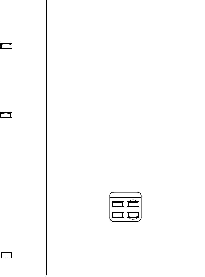
The STM-100 / MF keyboard is divided into two separate functional groups. The keys to the left of the LCD display are system control keys and the keys to the right of the display are data entry and programming keys. All keys are sensed when depressed and must be released to cause further action. The exceptions to this rule are the (LIFE) and (ARROW) keys. These keys will cause continuous action if held depressed. An audible beep will accompany each key activation. The beeper may be disabled if desired. See Section 2.7.
SHUTTER |
SENSOR |
|
DATA ENTRY |
|
OPEN |
ZERO |
|
PROGRAM |
|
|
DENS Z-FACT |
END THK SP THK |
SP TMR TOOL |
DATA |
CLOSE |
LIFE |
SP TIME |
ENTER |
|
|
XTAL FAIL |
PGM |
|
|
|
SHUTTER |
SP THICK |
COM |
|
instruments |
STM - 100 / MF THICKNESS / RATE MONITOR |
|
Figure 2.1: STM-100 / MF Front Panel.
SYSTEM CONTROL KEY GROUP
SHUTTER SENSOR
OPEN ZERO
CLOSE LIFE
Figure 2.2: System Control Keys.
SHUTTER OPEN
Activating the SHUTTER OPEN key will cause the internal shutter relay contacts to close. This relay is typically used to control a deposition system source shutter. The LCD display (SHUTTER) legend will be visible when the shutter relay is active. This key is active at all times and states (Program and Normal) of the STM-100 / MF. A remote input duplicating this key function is also provided.
SECTION 2.1
SECTION 2.2
SHUTTER
OPEN
CLOSE
Shutter Keys
Page 2 - 1 |
OPERATION AND PROGRAMMING |
ZERO Key
ZERO
Crystal Life Key
LIFE
SECTION 2.3
Program Key
PROGRAM
SHUTTER CLOSE
The SHUTTER CLOSE key provides the reverse function of the SHUTTER OPEN key. This key is active at all times and states of the STM-100 / MF. A remote input duplicating this key function is also provided.
ZERO
The ZERO key provides two functions, "THICKNESS ZERO" and "TIMER ZERO". Activating the key will cause any accumulated reading in the thickness display to be set to zero, thus providing a new accumulation reference point. It will also reset the elapsed timer and display to the setpoint value contained in the program memory. Any setpoint relays that may have been closed at the time of the "ZERO" key operation will be reset to the open state. This key is inactive in the PROGRAM mode. Remote inputs providing separate operation of the THICKNESS ZERO and TIMER ZERO operations are also provided. Note that during a Crystal Fail condition, the Zero key does not function.
LIFE
Activating the CRYSTAL LIFE key will provide the user with a measure of remaining possible sensor crystal life. This information is expressed in percent with 100% representing a new sensor crystal and 0% indicating a fully loaded sensor crystal (1MHz frequency shift). This information is presented where rate information is normally shown. This data should serve as an indicator for the need to change the sensor crystal. The frequency of the sensor crystal to the nearest kilohertz is also presented. This information is shown where accumulated thickness data is normally displayed. A new sensor crystal should indicate close to 99% life and a frequency near 5.950 MHz. This key function is inactive in the PROGRAM mode. Activating this key during a CRYSTAL FAIL condition may result in a blank data display. The LIFE display is active as long as the LIFE key is held depressed.
DATA ENTRY AND PROGRAMMING GROUP
DATA ENTRY
PROGRAM
ENTER DATA
Figure 2.3: Data Entry And Programming Keys.
PROGRAM
Activation of the PROGRAM key places the instrument in a mode wherein the internal parameter variables may be viewed or modified. Data view operation is always available whereas, data modification may be inhibited by a user option switch on the rear panel. If the instrument is in the PROGRAM mode, depressing the PROGRAM key will return the unit to the normal display mode. Six variable parameters, for each of nine films of the STM-100 / MF
OPERATION AND PROGRAMMING |
Page 2 - 2 |
may be programmed by the user. Two of these material constants are needed to provide correct thickness and rate information for a particular film material and one is a constant used to correct for system sensor and substrate geometry variations. Three setpoint variables are provided to activate relay events. Two of these are related to thickness and one to elapsed time. These variables and their meanings are discussed in detail in Section 2.4.
ENTER
The ENTER key has two functions. It is used (1) to sequence through the six parameter variables, one parameter for each press of the ENTER key, and (2) to place modified variable data into the non-volatile storage memory of the instrument. This data will be retained until modified by the user even with no power to the instrument. A legend on the LCD display will indicate which variable parameter data is being displayed. Any modifications to parameter data occur in the display memory only, and will cause the associated parameter legend to flash. The flashing legend indicates that a parameter change has been made but has not yet been saved in memory. To store the data in memory the ENTER key must be pressed. Exiting the PROGRAM mode (via the PROGRAM key) while a parameter legend is flashing does not cause the modified data to be saved. Previously saved parameter data will be retained. The ENTER key only functions in the PROGRAM mode.
ARROW KEYS
The ARROW keys are used to select the active film and to increment or decrement the displayed parameter variable data in order to achieve the desired value. The rate of incremental change will increase as the key is held depressed. This will speed up parameter changes covering a large dynamic data range. Letting up on the key and then resuming key depression will reset the rate of change to the slowest rate and it will again increase with time as the key remains depressed.
FILM PARAMETERS
The STM-100 / MF utilizes a high contrast liquid crystal display for the viewing device. All measurement data, instrument status, and program variable operations are viewable on the display. A three or four digit parameter display and a four digit time display (min:sec) are used to display the dynamic data.
Enter Key
ENTER
Arrow Keys
DATA
SECTION 2.4
LCD Data Displays
Page 2 - 3 |
OPERATION AND PROGRAMMING |

Film Number
Parameter
Figure 2.4: LCD Data Areas.
The STM-100 / MF incorporates six programmable parameter variables for each of nine films programmable by the user. Three variables are used by the thickness equation and are related to material physical constants and system geometry (Density, Z-Factor, and Tooling). The three remaining parameters are used as setpoint values to activate the internal relays on the I/O connector.
Each variable has a specific LCD legend associated with it. These legends are only active in the PROGRAM mode and only one will be on at a time. Each parameter is discussed in more detail below.
Figure 2.5: LCD Variable Parameter Legends.
After entering the program mode by pushing the Program Button the current film number is displayed in the upper left hand corner of the LCD display. (FL.n, n is 1 through 9). Refer to Figure 2.6.
PROGRAM
ENTER DATA
Figure 2.6: Film Number Parameter.
At this point the current film's parameters may be reviewed or changed or a new current film selected. To select a new current film the film number is
OPERATION AND PROGRAMMING |
Page 2 - 4 |
increased or decreased by using the up and down arrow keys. Pushing the enter button selects the film number shown to be the current film and displays the first parameter (density) of that film. Each of the film parameters can now be reviewed or changed by using the DATA keys and / or the ENTER key.
WARNING |
When leaving the Program Mode, the last Selected |
|||||||||||||
|
|
|
|
|
|
FILM is the current active FILM. |
||||||||
|
|
|
|
|
|
|
|
|
|
|
|
|
|
|
|
|
|
|
|
|
|
|
|
DENSITY |
|||||
|
|
|
|
|
|
|
|
|
|
|
|
|
|
|
|
|
|
|
|
|
|
|
|
|
|
|
|
|
|
|
|
|
|
|
|
|
|
|
|
|
|
|
|
|
|
|
|
|
|
|
|
|
|
|
|
|
|
|
|
|
|
|
|
|
|
|
|
|
|
|
|
|
|
|
|
|
|
|
|
|
|
|
|
|
|
|
|
|
|
|
|
|
|
|
|
|
|
|
|
|
|
|
|
|
|
|
|
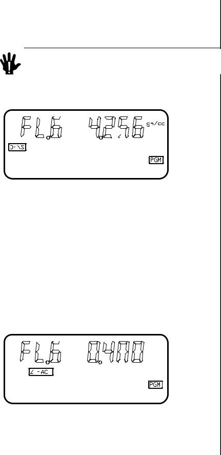
Figure 2.7: Density Parameter. |
|
||||||||||||||||
LEGEND |
DENS |
|
||||||||||||||||||
RANGE |
0.500 to 99.99 |
|
||||||||||||||||||
UNITS |
gm/cc |
|
||||||||||||||||||
The DENSITY parameter refers to the measured material density in |
Density Parameter |
|||||||||||||||||||
|
||||||||||||||||||||
gm/cc. This constant is normally the bulk material value but is sometimes |
|
|||||||||||||||||||
different due to deposition and film growth conditions. This value is utilized in |
|
|||||||||||||||||||
the thickness equation to convert measured mass to a thickness value. See |
|
|||||||||||||||||||
Table 4.1 for an extensive value list. See Section 4.2 for calibration |
|
|||||||||||||||||||
information. |
|
|
|
|
|
|
|
|
|
|
|
|
|
|
|
|
|
|
|
|
|
|
|
|
|
|
|
|
|
|
|
|
|
|
|
Z-FACTOR |
|
||||
|
|
|
|
|
|
|
|
|
|
|
|
|
|
|
|
|
|
|
|
|
|
|
|
|
|
|
|
|
|
|
|
|
|
|
|
|
|
|
|
|
|
|
|
|
|
|
|
|
|
|
|
|
|
|
|
|
|
|
|
|
|
|
|
|
|
|
|
|
|
|
|
|
|
|
|
|
|
|
|
|
|
|
|
|
Figure 2.8: Z-Factor Parameter. |
LEGEND |
Z-FACT |
RANGE |
0.100 to 9.999 |
UNITS |
NONE |
|
|
Page 2 - 5 |
OPERATION AND PROGRAMMING |

Z-Factor Parameter
End Thickness
The Z-Factor parameter refers to the elastic properties of the measured material. This value is utilized in the thickness equation to match the acoustical properties of the film being measured to the acoustic properties of the base quartz material of the sensor crystal. This correction is necessary to insure accurate measurements when sensor crystal shifts of greater than 15% are realized. See Table 4.1 for an extensive material value list. See Section 4.2 for calibration information.
END THICKNESS
|
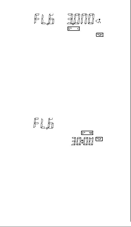
Figure 2.9: End Thickness Parameter. |
LEGEND |
END THK |
RANGE |
0 to 9999 |
UNITS |
KILO ANGSTROMS (1 Angstrom = 10-10 meters) |
The END THICKNESS parameter is used to provide a trigger setpoint for the STM-100 / MF Shutter Relay contacts. If the shutter relay contacts are closed by operating the front panel shutter closed button or by remote input. These contacts will return to the open state when the thickness display value becomes equal to or exceeds the END THICKNESS SETPOINT value. The STM-100 / MF Shutter Relay contacts are normally used to automatically control a deposition system source shutter. This is a trigger event and will only effect shutter status at the time the event occurs. If the shutter relay contacts were already open at the time of the event the event will be ignored. A setpoint value of 0.000 kÅ causes the setpoint function to be ignored.
OPERATION AND PROGRAMMING |
Page 2 - 6 |
SETPOINT THICKNESS
|
|
|
|
|
Figure 2.10: Set Point Thickness Parameter. |
LEGEND |
SP THK |
|
RANGE |
0 to 9999 |
|
UNITS |
KILO ANGSTROMS |
|
The SETPOINT THICKNESS parameter is used to provide a comparison point for the STM-100 / MF Thickness Setpoint Relay. This set of relay contacts will be closed whenever the thickness display equals or exceeds the setpoint value. A setpoint value of 0.000 kÅ causes the thickness setpoint function to be ignored.
SETPOINT TIMER
|
|
|
|
|
Figure 2.11: Set Point Timer Parameter. |
LEGEND |
SP TMR |
|
RANGE |
00:00 to 99:59 |
|
UNITS |
MIN:SEC |
|
The SETPOINT TIMER parameter is used to provide a comparison point for the STM-100 / MF Timer Setpoint Relay. The internal STM-100 / MF timer is pre-set with the setpoint value whenever the front panel ZERO key, or a remote ZERO TIMER input, is activated. The Timer Relay contacts are opened at this time and the timer display begins counting downward toward zero. When the timer display reaches zero the relay contacts are closed and the display timer begins counting in an upwards fashion. A setpoint value of 00:00 will cause the timer setpoint function to be ignored.
Setpoint Thickness
Parameter
Setpoint Timer
Page 2 - 7 |
OPERATION AND PROGRAMMING |

Tooling Factor
Parameter
SECTION 2.5
TOOLING
|
|
|
|
|
Figure 2.12: Tooling Parameter. |
LEGEND |
TOOL |
|
RANGE |
10.0 to 399 |
|
UNITS |
PERCENT |
|
The TOOLING parameter is used as a correction factor to compensate for geometric position differences between the location of the sensor and the target substrate. Correction is required both the substrate and sensor see the material source in an identical manner, unless for this case, the Tooling Parameter is set to 100%. Generally, if the sensor is farther from the source than the substrate, the tooling will be set to >100%. If the sensor is closer to the source, the tooling will be set to < 100%. See Section 4.2 for calibration information.
USER CONFIGURATION SWITCHES
On the rear panel of the STM-100 / MF a twelve selection configuration switch is located. The settings of this switch allow the user to select various system operational modes. All communications related variables are also set here. Switches 1 thru 4 may be changed at any time and will have immediate effect. Switches 5 thru 12 are only read at the time of power turn on.
OPERATION AND PROGRAMMING |
Page 2 - 8 |
CONFIGURATION |
|
|
|
|
|
|
||||||||||
|
|
|
|
SWITCH |
|
|
|
|
|
|
||||||
|
|
|
|
|
|
|
|
|
|
BINARY DEVICE ADDRESS |
|
|
|
|||
|
|
|
|
|
|
|
|
|
|
|
|
|
||||
|
|
|
|
|
|
|
|
|
|
SW8=MS BIT SW12=LS BIT |
|
|
|
|||
|
|
|
|
|
|
|
|
|
|
|
|
|||||
|
|
|
|
|
|
|
|
|
|
SW 8 SW9 SW10 SW11 SW12 |
|
|
||||
|
|
|
|
|
|
|
|
|
|
OFF |
OFF |
OFF |
OFF |
OFF |
= 0 |
|
|
|
|
|
|
|
|
|
|
|
|||||||
|
|
|
|
|
|
|
|
|
|
OFF |
OFF |
OFF |
ON |
OFF |
= 0 |
|
|
|
|
|
|
|
|
|
|
|
ON |
OFF |
ON |
OFF |
ON |
= 0 |
|
|
|
|
|
|
|
|
|
|
|
|||||||
|
|
|
|
|
|
|
|
|
|
SERIAL BAUD RATE |
|
|
see Note: |
|
||
|
|
|
|
|
|
|
|
|
|
|
|
|||||
|
|
|
|
|
|
|
|
|
|
SW 6 |
|
SW7 |
|
|
|
|
|
|
|
|
|
|
|
|
|
|
OFF |
|
OFF |
= 300 |
|
|
|
|
|
|
|
|
|
|
|
|
|
|
|
|
|
|||
|
|
|
|
|
|
|
|
|
|
OFF |
|
ON |
= 1200 |
|
|
|
|
|
|
|
|
|
|
|
|
|
ON |
|
OFF |
= 2400 |
|
|
|
|
|
|
|
|
|
|
|
|
|
ON |
|
ON |
= 9600 |
|
|
|
|
|
|
|
|
|
|
|
|
|
|
|
|
||||
|
|
|
|
|
|
|
|
|
|
PROTOCOL |
|
ON = SEMI |
OFF = SYCON |
|
||
|
|
|
|
|
|
|
|
|
|
|
||||||
|
|
|
|
|
|
|
|
|
|
NEGATIVE RATES |
ON = ENABLE OFF = DISABLE |
|
||||
|
|
|
|
|
|
|
|
|
|
|||||||
|
|
|
|
|
|
|
|
|
|
FREQUENCY MODE |
ON = ENABLE OFF = DISABLE |
|
||||
|
|
|
|
|
|
|
|
|
|
|||||||
|
|
|
|
|
|
|
|
|
|
ANALOG OUTPUT |
ON = THICK |
OFF = RATE |
|
|||
|
|
|
|
|
|
|
|
|
|
|||||||
|
|
|
|
|
|
|
|
|
|
PARAMETER LOCK |
ON = LOCK |
OFF = UNLOCK |
|
|||
|
|
|
|
|
|
|
|
|
|
|||||||
|
|
NOTE: Switch settings involving communications functions are sensed at power up only. |
|
|||||||||||||
|
|
|
|
|
|
|
Figure 2.13: Configuration Switch Settings. |
|
||||||||
|
|
|
|
|
|
|
SWITCH FUNCTION DEFINITIONS |
|
||||||||
SW1 - PARAMETER LOCK |
|
|
|
|
|
|
||||||||||
|
|
|
|
When on, stored parameter data cannot be modified via the front |
|
|||||||||||
|
|
|
|
panel. This switch is sensed at all times. |
|
|||||||||||
SW2 - RECORDER FUNCTION |
|
|
|
|
|
|
||||||||||
|
|
|
|
When on, the analog output will provide thickness information. |
|
|||||||||||
|
|
|
|
Rate information is presented in the off state. This switch is |
|
|||||||||||
|
|
|
|
sensed at all times. See Section 3.6. |
|
|||||||||||
SW3 - FREQUENCY MODE |
|
|
|
|
|
|
||||||||||
|
|
|
|
When on, the unit will display seven digits of sensor frequency to |
|
|||||||||||
|
|
|
|
a resolution of one Hertz. All other instrument functions remain |
|
|||||||||||
|
|
|
|
normal. This switch is active at all times. |
Configuration |
|||||||||||
SW4 - NEGATIVE LIMITS |
|
|
|
|
|
|||||||||||
|
|
|
|
|
|
|||||||||||
|
|
|
|
When on, both thickness setpoints and their associated relays will |
|
|||||||||||
|
|
|
|
activate on negative thickness data only. This switch is sensed at |
|
|||||||||||
|
|
|
|
all times. |
|
|
|
|
|
|
||||||
SW5 - SERIAL COMMUNICATIONS FORMAT |
|
|
||||||||||||||
|
|
|
|
When on, the RS-232 serial communications channel will respond |
|
|||||||||||
|
|
|
|
to SEMI STANDARD SECS-II formatted commands. Sycon |
|
|||||||||||
|
|
|
|
formatted commands are valid for the off state. This switch is |
|
|||||||||||
|
|
|
|
sensed only at power-up. |
|
|
|
|
||||||||
SW6 & SW7 - BAUD RATE SELECTION |
|
|
|
|
||||||||||||
|
|
|
|
These two switch settings in combination select one of four baud |
|
|||||||||||
|
|
|
|
rates for the RS-232 serial communications channel. These |
|
|||||||||||
|
|
|
|
switches are sensed only during power-up. |
|
|||||||||||
|
|
|
|
|||||||||||||
Page 2 - 9 |
|
OPERATION AND PROGRAMMING |
||||||||||||||

SW6 |
SW7 |
BAUD |
OFF |
OFF |
300 |
OFF |
ON |
1200 |
ON |
OFF |
2400 |
ON |
ON |
9600 |
Table 2.1: Baud Rate Switch Settings
SW8, SW9, SW10, SW11, SW12 DEVICE ADDRESS SELECTION
These switches in combination select the device address for the instrument when operating with the SECS RS-232 protocol or with either the IEEE-488 or BITBUS communications option cards. These options allow multiple devices to operate on a single bus, and only the individual addressing prevents response conflicts. Switch coding is in binary 1 of 32 format with SW8 the MSB and SW12 the LSB. These switches are sensed only during powerup. See Table 2.2 for a list of addresses.
OPERATION AND PROGRAMMING |
Page 2 - 10 |
Loading...