


 Loading...
Cover Page
O P E R A T I N G M A N U A L
Front Load Single and Dual
Sensors
PN 074-156N

Title Page
O P E R A T I N G M A N U A L
Front Load Single and Dual
Sensors
PN 074-156N


 ®
®
www.inficon.com reachus@inficon.com
©2014 INFICON
Trademarks
The trademarks of the products mentioned in this manual are held by the companies that produce them.
RateWatcher™ is a registered trademark of INFICON GmbH.
Teflon® and Viton® are registered trademarks of E. I. duPont de Nemours Company or its affiliates.
Swagelok® is a registered trademark of Swagelok Company.
VCR®, VCO®, and Ultra-Torr® are registered trademarks of Cajon Company.
ConFlat® is a registered trademark of Varian Corporation.
FOMBLIN® is a registered trademark of Ausimont SpA.
Microdot® is a registered trademark of Microdot Corp.
Scotch-Brite™ is a trademark of 3M.
All other brand and product names are trademarks or registered trademarks of their respective companies.
Disclaimer
The information contained in this manual is believed to be accurate and reliable. However, INFICON assumes no responsibility for its use and shall not be liable for any special, incidental, or consequential damages related to the use of this product.
Due to our continuing program of product improvements, specifications are subject to change without notice.
Copyright
©2014 All rights reserved.
Reproduction or adaptation of any part of this document without permission is unlawful.

Warranty
WARRANTY AND LIABILITY - LIMITATION: Seller warrants the products manufactured by it, or by an affiliated company and sold by it, and described on the reverse hereof, to be, for the period of warranty coverage specified below, free from defects of materials or workmanship under normal proper use and service. The period of warranty coverage is specified for the respective products in the respective Seller instruction manuals for those products but shall not be less than one (1) year from the date of shipment thereof by Seller. Seller's liability under this warranty is limited to such of the above products or parts thereof as are returned, transportation prepaid, to Seller's plant, not later than thirty (30) days after the expiration of the period of warranty coverage in respect thereof and are found by Seller's examination to have failed to function properly because of defective workmanship or materials and not because of improper installation or misuse and is limited to, at Seller's election, either (a) repairing and returning the product or part thereof, or (b) furnishing a replacement product or part thereof, transportation prepaid by Seller in either case. In the event Buyer discovers or learns that a product does not conform to warranty, Buyer shall immediately notify Seller in writing of such non-conformity, specifying in reasonable detail the nature of such non-conformity. If Seller is not provided with such written notification, Seller shall not be liable for any further damages which could have been avoided if Seller had been provided with immediate written notification.
THIS WARRANTY IS MADE AND ACCEPTED IN LIEU OF ALL OTHER WARRANTIES, EXPRESS OR IMPLIED, WHETHER OF MERCHANTABILITY OR OF FITNESS FOR A PARTICULAR PURPOSE OR OTHERWISE, AS BUYER'S EXCLUSIVE REMEDY FOR ANY DEFECTS IN THE PRODUCTS TO BE SOLD HEREUNDER. All other obligations and liabilities of Seller, whether in contract or tort (including negligence) or otherwise, are expressly EXCLUDED. In no event shall Seller be liable for any costs, expenses or damages, whether direct or indirect, special, incidental, consequential, or other, on any claim of any defective product, in excess of the price paid by Buyer for the product plus return transportation charges prepaid.
No warranty is made by Seller of any Seller product which has been installed, used or operated contrary to Seller's written instruction manual or which has been subjected to misuse, negligence or accident or has been repaired or altered by anyone other than Seller or which has been used in a manner or for a purpose for which the Seller product was not designed nor against any defects due to plans or instructions supplied to Seller by or for Buyer.
This manual is intended for private use by INFICON® Inc. and its customers. Contact INFICON before reproducing its contents.
NOTE: These instructions do not provide for every contingency that may arise in connection with the installation, operation or maintenance of this equipment. Should you require further assistance, please contact INFICON.
www.inficon.com reachus@inficon.com

PN 074-156N
Front Load Single and Dual Sensors Operating Manual
Table Of Contents
Cover Page
Title Page
Trademarks
Disclaimer
Copyright
Warranty
Chapter 1
Introduction
1.1 Introduction. . . . . . . . . . . . . . . . . . . . . . . . . . . . . . . . . . . . . . . . . . . . . . . . . . 1-1 1.2 Definition of Notes, Cautions and Warnings. . . . . . . . . . . . . . . . . . . . . . . . . 1-2 1.3 How to Contact INFICON . . . . . . . . . . . . . . . . . . . . . . . . . . . . . . . . . . . . . . . 1-2 1.3.1 Returning Sensor to INFICON . . . . . . . . . . . . . . . . . . . . . . . . . . . . . . . . . . . 1-3 1.4 Unpacking and Inspection . . . . . . . . . . . . . . . . . . . . . . . . . . . . . . . . . . . . . . 1-3 1.4.1 Single Sensor Configuration Overview and Parts . . . . . . . . . . . . . . . . . . . . 1-4 1.4.2 Dual Sensor Configuration Overview and Parts . . . . . . . . . . . . . . . . . . . . . . 1-5 1.5 Front Load Single Sensors (PN SL-XXXXX) . . . . . . . . . . . . . . . . . . . . . . . . 1-6 1.5.1 Specifications . . . . . . . . . . . . . . . . . . . . . . . . . . . . . . . . . . . . . . . . . . . . . . . . 1-7 1.5.2 Materials . . . . . . . . . . . . . . . . . . . . . . . . . . . . . . . . . . . . . . . . . . . . . . . . . . . . 1-8 1.5.3 Installation Requirements . . . . . . . . . . . . . . . . . . . . . . . . . . . . . . . . . . . . . . . 1-8 1.5.4 Single Sensor Drawings . . . . . . . . . . . . . . . . . . . . . . . . . . . . . . . . . . . . . . . . 1-9 1.6 Front Load Dual Sensor (PN DL-AXXX). . . . . . . . . . . . . . . . . . . . . . . . . . . 1-14 1.6.1 Specifications . . . . . . . . . . . . . . . . . . . . . . . . . . . . . . . . . . . . . . . . . . . . . . . 1-14 1.6.2 Materials . . . . . . . . . . . . . . . . . . . . . . . . . . . . . . . . . . . . . . . . . . . . . . . . . . . 1-15 1.6.3 Installation Requirements . . . . . . . . . . . . . . . . . . . . . . . . . . . . . . . . . . . . . . 1-15 1.6.4 Dual Sensor Drawings . . . . . . . . . . . . . . . . . . . . . . . . . . . . . . . . . . . . . . . . 1-16 1.7 Shutter Module (PN 750-210-G1 and 750-210-G3) . . . . . . . . . . . . . . . . . . 1-19 1.7.1 Specifications . . . . . . . . . . . . . . . . . . . . . . . . . . . . . . . . . . . . . . . . . . . . . . . 1-19 1.7.2 Shutter Module Drawings . . . . . . . . . . . . . . . . . . . . . . . . . . . . . . . . . . . . . . 1-20 1.8 Feedthroughs . . . . . . . . . . . . . . . . . . . . . . . . . . . . . . . . . . . . . . . . . . . . . . . 1-23 1.8.1 Specifications for 2.54 cm (1 in.) Bolt . . . . . . . . . . . . . . . . . . . . . . . . . . . . . 1-23 1.8.2 Specifications for CF40 (2-3/4 in. ConFlat) . . . . . . . . . . . . . . . . . . . . . . . . 1-24 1.8.3 Feedthrough Drawings . . . . . . . . . . . . . . . . . . . . . . . . . . . . . . . . . . . . . . . . 1-25
TOC - 1

Front Load Single and Dual Sensors Operating Manua
Chapter 2
Sensor Installation
2.1 Pre-installation Sensor Check . . . . . . . . . . . . . . . . . . . . . . . . . . . . . . . . . . . 2-1
2.1.1Sensor Check with XTC/3, IC6, or Cygnus 2
Deposition Controller . . . . . . . . . . . . . . . . . . . . . . . . . . . . . . . . . . . . . . . . . . 2-1
2.1.2Sensor Check with STM-2XM, STM-3, SQM-160, SQC-310,
SQM-242, or IQM-233 Deposition Controller/Monitor . . . . . . . . . . . . . . . . . 2-2 2.1.3 Sensor Check with Q-pod™ or STM-2 Deposition Monitor. . . . . . . . . . . . . . 2-3 2.1.4 Sensor Shutter Check . . . . . . . . . . . . . . . . . . . . . . . . . . . . . . . . . . . . . . . . . 2-4 2.2 Sensor Installation Guidelines . . . . . . . . . . . . . . . . . . . . . . . . . . . . . . . . . . . 2-4 2.3 Sensor Installation Procedure . . . . . . . . . . . . . . . . . . . . . . . . . . . . . . . . . . . 2-7 2.3.1 Tube Bending . . . . . . . . . . . . . . . . . . . . . . . . . . . . . . . . . . . . . . . . . . . . . . . 2-10 2.4 Sensor Shutter Module Installation on Existing Equipment . . . . . . . . . . . . 2-11
2.4.1Shutter Module Installation on a
Standard Crystal Sensor (PN SL-A0XXX) . . . . . . . . . . . . . . . . . . . . . . . . . 2-11
2.4.2Shutter Module Installation on a
Right Angle Crystal Sensor (PN SL-B0XXX) . . . . . . . . . . . . . . . . . . . . . . . 2-11
Chapter 3
Solenoid Valve Assembly Installation
3.1 Introduction. . . . . . . . . . . . . . . . . . . . . . . . . . . . . . . . . . . . . . . . . . . . . . . . . . 3-1 3.2 Installation with a 2.54 cm (1 in.) Bolt Feedthrough . . . . . . . . . . . . . . . . . . . 3-1 3.3 Installation with a CF40 (2-3/4 in. ConFlat) Feedthrough. . . . . . . . . . . . . . . 3-2 3.4 Pneumatic Connections . . . . . . . . . . . . . . . . . . . . . . . . . . . . . . . . . . . . . . . . 3-4 3.5 Electrical Connections . . . . . . . . . . . . . . . . . . . . . . . . . . . . . . . . . . . . . . . . . 3-4 3.6 Solenoid Valve Drawings . . . . . . . . . . . . . . . . . . . . . . . . . . . . . . . . . . . . . . . 3-4
Chapter 4
Maintenance and Spare Parts
4.1 General Precautions. . . . . . . . . . . . . . . . . . . . . . . . . . . . . . . . . . . . . . . . . . . 4-1 4.1.1 Handle the Crystal with Care . . . . . . . . . . . . . . . . . . . . . . . . . . . . . . . . . . . . 4-1 4.1.2 Use the Optimum Crystal Type . . . . . . . . . . . . . . . . . . . . . . . . . . . . . . . . . . 4-1 4.1.3 Maintain the Temperature of the Crystal . . . . . . . . . . . . . . . . . . . . . . . . . . . 4-2 4.1.4 Crystal Concerns when Opening the Chamber . . . . . . . . . . . . . . . . . . . . . . 4-2
4.2 Crystal Replacement Instructions. . . . . . . . . . . . . . . . . . . . . . . . . . . . . . . . . 4-2 4.3 Sensor Maintenance . . . . . . . . . . . . . . . . . . . . . . . . . . . . . . . . . . . . . . . . . . 4-5 4.3.1 Adjusting the Leaf Spring . . . . . . . . . . . . . . . . . . . . . . . . . . . . . . . . . . . . . . . 4-5 4.3.2 Cleaning the Crystal Holder . . . . . . . . . . . . . . . . . . . . . . . . . . . . . . . . . . . . . 4-6 4.3.3 Adjusting the Crystal Holder Retainer Spring. . . . . . . . . . . . . . . . . . . . . . . . 4-7 4.3.4 Replacing the Finger Spring. . . . . . . . . . . . . . . . . . . . . . . . . . . . . . . . . . . . . 4-8 4.3.5 Lubricating the Shutter Module . . . . . . . . . . . . . . . . . . . . . . . . . . . . . . . . . . 4-9 4.4 Spare Parts and Accessories . . . . . . . . . . . . . . . . . . . . . . . . . . . . . . . . . . . 4-10
TOC - 2
PN 074-156N

Front Load Single and Dual Sensors Operating Manual
Chapter 5
Troubleshooting
5.1 Troubleshooting Tools . . . . . . . . . . . . . . . . . . . . . . . . . . . . . . . . . . . . . . . . . 5-1
5.1.1 Symptom, Cause, Remedy. . . . . . . . . . . . . . . . . . . . . . . . . . . . . . . . . . . . . . 5-1
5.1.2 Digital Multimeter . . . . . . . . . . . . . . . . . . . . . . . . . . . . . . . . . . . . . . . . . . . . . 5-3
5.1.2.1 Electrical Isolation Check . . . . . . . . . . . . . . . . . . . . . . . . . . . . . . . . . . . . . . . 5-4
5.1.2.2 Electrical Continuity Check. . . . . . . . . . . . . . . . . . . . . . . . . . . . . . . . . . . . . . 5-6
5.1.3 Crystal Sensor Emulator. . . . . . . . . . . . . . . . . . . . . . . . . . . . . . . . . . . . . . . 5-10
5.1.3.1 Measurement System Check . . . . . . . . . . . . . . . . . . . . . . . . . . . . . . . . . . . 5-11
5.1.3.2 Crystal Holder and Ceramic Retainer Check . . . . . . . . . . . . . . . . . . . . . . . 5-12
5.1.3.3 Feedthrough and In-Vacuum Cable Check . . . . . . . . . . . . . . . . . . . . . . . . 5-13
5.1.3.4 Crystal Life Readings . . . . . . . . . . . . . . . . . . . . . . . . . . . . . . . . . . . . . . . . . 5-13
PN 074-156N
TOC - 3

Front Load Single and Dual Sensors Operating Manua
This page is intentionally blank.
PN 074-156N
TOC - 4
PN 074-156N
Front Load Single and Dual Sensors Operating Manual
Chapter 1
Introduction
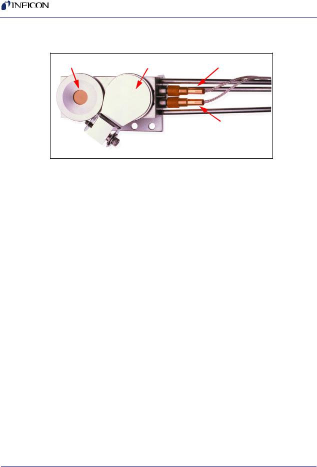
1.1 Introduction
INFICON Front Load Sensors (see Figure 1-1) offer proven reliability and durability combined with excellent thermal stability. The front load design allows for easy insertion of the crystal holder in applications lacking sufficient room for side access. Because they are assembled mechanically rather than soldered, parts can conveniently be replaced in the field. Sensors can be ordered individually or in a sensor and feedthrough combination that can be either welded or assembled with Ultra-Torr® O-ring compression fittings.
Figure 1-1 Front Load Sensors
The Front Load Sensor comes in two styles: Single or Dual.
The Front Load Single Sensor comes in two sensor configurations:
Standard or Right Angle (Compact).
Standard configuration—installed from the side or bottom of the chamber, with the cooling tubes aligned parallel to the crystal face.
Right Angle configuration—installed through the top of the vacuum system, with the water cooling tubes aligned perpendicular to the crystal face.
For the Front Load Dual Sensor, a Standard configuration (i.e., waterlines parallel to the crystal face) is available.
Optionally, single sensors can be ordered with a pneumatically driven crystal shutter to protect the crystal during source warm up, or when the sensor is not used during deposition of an alternate material, or to extend crystal life when used with RateWatcher™ or rate sampling.
NOTE: Crystal shutters are standard on Front Load Dual Sensors.
1 - 1
Front Load Single and Dual Sensors Operating Manual
1.2 Definition of Notes, Cautions and Warnings
Before using this manual, please take a moment to understand the Cautions and Warnings used throughout. They provide pertinent information that is useful in achieving maximum instrument efficiency while ensuring personal safety.
NOTE: Notes provide additional information about the current topic.
CAUTION
Failure to heed these messages could result in damage to the instrument.
WARNING
Failure to heed these messages could result in personal injury.
1.3 How to Contact INFICON
Worldwide customer support information is available under Support >> Support Worldwide at www.inficon.com:
Sales and Customer Service
Technical Support
Repair Service
When communicating with INFICON about a Front Load Sensor, please have the following information readily available:
The Sales Order or Purchase Order number of the Front Load Sensor purchase.
The Lot Identification Code, located on the side surface of the sensor head.
A description of the problem.
The exact wording of any error messages that may have been received.
An explanation of any corrective action that may have already been attempted.
PN 074-156N
1 - 2

PN 074-156N
Front Load Single and Dual Sensors Operating Manual
1.3.1 Returning Sensor to INFICON
Do not return any sensor component to INFICON before speaking with a Customer Support Representative and obtaining a Return Material Authorization (RMA) number. Front Load Sensors will not be serviced without an RMA number.
Packages delivered to INFICON without an RMA number will be held until the customer is contacted. This will result in delays in servicing the Front Load Sensor.
Prior to being given an RMA number, a completed Declaration Of Contamination (DoC) form will be required. DoC forms must be approved by INFICON before an RMA number is issued. INFICON may require that the sensor be sent to a designated decontamination facility, not to the factory.
1.4Unpacking and Inspection
1If the Front Load Sensor has not been removed from its packaging, do so now. The sensor and accessories are packaged in a single cardboard carton with a rigid foam insert. Carefully remove the packaged accessories before removing the sensor.
2Carefully examine the sensor for damage that may have occurred during shipping. It is especially important to note obvious rough handling on the outside of the container. Immediately report any damage to the carrier and to INFICON.
NOTE: Do not discard the packaging material until inventory has been taken and installation is successful.
3Refer to the invoice and the information contained in section 1.4.1 or section 1.4.2 on page 1-5 to take inventory.
4To install the sensor, see Chapter 2, Sensor Installation.
5For additional information or technical assistance, contact INFICON (refer to section 1.3).
1 - 3

Front Load Single and Dual Sensors Operating Manual
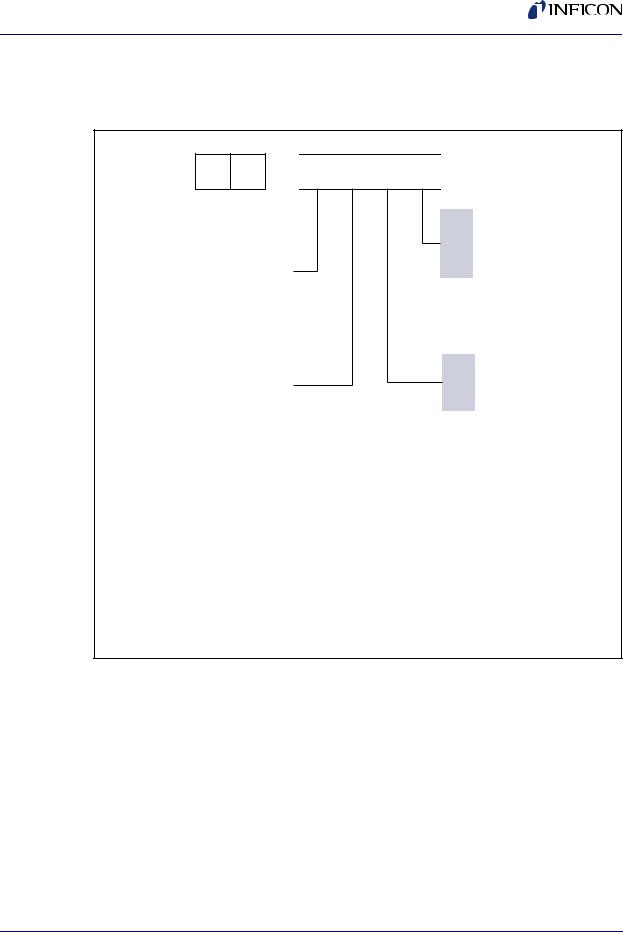
1.4.1 Single Sensor Configuration Overview and Parts
Front Load Single Sensor . . . . . . . . . . . SL-XXXXX, see Figure 1-2.
Figure 1-2 Front Load Single Sensor configurations
S L
Type of Sensor
(Includes in-vacuum cable. Crystals sold separately.)
Standard sensor (water lines parallel)
Right angle sensor (water lines perpendicular)
Shutter Assembly – SEE NOTE 4
None
Standard shutter
Length of Sensor –
SEE NOTES 1 and 3
Standard length: 20.3 to 71.1 cm (8 to 28 in.) includes 78.1 cm (30.75 in.) in-vacuum cable. SEE NOTE 6
Extended length: 71.1 to 121.9 cm (28 to 48 in.) includes 152.4 cm (60 in.) in-vacuum cable. SEE NOTE 6
– |
|
|
|
|
|
|
|
|
|
|
|
Feedthrough Connection – |
|
|
|
|
|
|
|
|
|
|
|
|
|
|
|
|
|
|
|
|
|
|
|
|
|
|
|
|
SEE NOTE 4 |
|
|
|
|
|
|
|
|
|
|
|
|
|
|
|
|
|
|
|
|
|
|
|
|
|
|
|
|
|
|
|
|
|
|
|
|
|
|
|
|
0 |
Sensor not connection to |
|
|
|
|
|
|
|
|
|
|
|
|
|
feedthrough |
|
|
|
|
|
|
|
|
|
|
|
|
7 |
Sensor welded to feedthrough |
|
|
|
|
|
|
|
|
|
|
|
|
||
A |
|
|
|
|
|
|
|
|
|
|
|
||
|
|
|
|
|
|
|
|
|
|
|
8 |
Feedthrough equipped with |
|
|
|
|
|
|
|
|
|
|
|
|
|||
B |
|
|
|
|
|
|
|
|
|
|
|
|
Ultra-Torr® compression fittings |
|
|
|
|
|
|
|
|
|
|
|
|
||
|
|
|
|
|
|
|
|
|
|
|
|
(allows for adjustable sensor |
|
|
|
|
|
|
|
|
|
|
|
|
|
|
length) |
|
|
|
|
|
|
|
|
|
|
|
|
|
|
|
|
|
|
|
|
|
|
|
|
|
|
|
Feedthrough – SEE NOTE 2 |
0 |
|
|
|
|
|
|
|
|
|
|
|
|
|
|
|
|
|
|
|
|
|
|
|
0 |
None |
||
1 |
|
|
|
|
|
|
|
|
|
|
|
3 |
1 in. bolt |
|
|
|
|
|
|
|
|
|
|||||
|
|
|
|
|
|
|
|
|
|||||
|
|
|
|
|
|
|
|
|
|
|
|
4 |
CF40 |
|
|
|
|
|
|
|
|
|
|
|
|||
|
|
|
|
|
|
|
|
|
|
|
|||
E |
|
|
|
|
|
|
NOTE 3: |
|
|||||
|
|
|
|
|
|
|
Sensor lengths are measured from center of the crystal to the |
||||||
|
|
|
|
|
|
|
vacuum side (sealing surface) of the feedthrough (see length |
||||||
|
|
|
|
|
|
|
|||||||
G |
|
|
|
|
|
|
specification form). |
|
|||||
|
|
|
|
|
|
NOTE 4: |
|
||||||
|
|
|
|
|
|
|
|
||||||
|
|
|
|
|
|
|
Sensors ordered with shutters and 1 in. bolt style feedthrough can |
||||||
|
|
|
|
|
|
|
only be welded (compression fittings not available). |
||||||
|
|
|
|
|
|
|
NOTE 5: |
|
|||||
NOTE 1:
Orders for a WELDED sensor/feedthrough combination cannot be accepted without a completed sensor length specification form (provided by INFICON). Once a welded sensor order is confirmed, it can not be canceled.
NOTE 2:
Feedthrough configuration varies depending on options selected (with or without shutter, type of feedthrough, etc). Example: SL-A0E37 uses feedthrough PN 002-042 while SL-A1E37 uses feedthrough PN 750-030-G1.
Front Load sensors ordered with a CF40 feedthrough and a shutter can not be welded due to dimensional limits of the CF40.
NOTE 6:
For sensors ordered without a weld connection (option “0” or “8”), tubes are made to a length of approximately 76.2 cm (30 in.) for “E” length and approximately 121.9 cm (48 in.) for “G” length sensors.
Operation with a 152.4 cm (60 in.) cable requires a monitor / controller with ModeLock technology (XTC/3, IC6, Cygnus 2).
Thin Film Manuals CD . . . . . . . . . . . . . . . . . . . . . . . PN 074-5000-G1 Crystal Snatcher. . . . . . . . . . . . . . . . . . . . . . . . . . . . PN 008-007
78.1 cm (30.75 in.) In-Vacuum Cable. . . . . . . . . . . . PN 007-044 (standard length)
152.4 cm (60 in.) In-Vacuum Cable . . . . . . . . . . . . . PN 321-039-G13 (extended length)
Molybdenum Disulfide in Alcohol . . . . . . . . . . . . . . . PN 750-191-G1 (provided only with shuttered sensors)
Tube Bender Kit . . . . . . . . . . . . . . . . . . . . . . . . . . . . PN 750-037-G1 (provided only with non-welded sensors)
1 - 4
PN 074-156N
PN 074-156N
Front Load Single and Dual Sensors Operating Manual
1.4.2 Dual Sensor Configuration Overview and Parts
Front Load Dual Sensor . . . . . . . . . . . . . DL-AXXX, see Figure 1-3.
Figure 1-3 Front Load Dual Sensor configurations
D L – 


Type of Sensor
(Includes in-vacuum cables.
Crystals sold separately.) |
|
Standard dual sensor |
A |
(water lines parallel to |
|
crystal face) with shutter |
|
Length of Sensor – |
|
SEE NOTES 1 and 3 |
|
Standard length – |
E |
20.3 to 71.1 cm (8 to 28 in.) |
|
includes two 78.1 cm (30.75 in.) |
|
in-vacuum cables. SEE NOTE 5 |
G |
Extended length – |
|
71.1 to 121.9 cm (28 to 48 in.) |
|
|
|
includes two 152.4 cm (60 in.) |
|
in-vacuum cables. SEE NOTE 5 |
|
Feedthrough Connection
SEE NOTE 4
0Sensor not connected to feedthrough
7Sensor welded to feedthrough
8Feedthrough equipped with Ultra-Torr® compression fittings (allows for adjustable sensor length)
Feedthrough
SEE NOTE 2
0 None
31 in. bolt
4CF40
NOTE 1:
Orders for a WELDED sensor/feedthrough combination cannot be accepted without a completed sensor length specification form (provided by INFICON). Once a welded sensor order is confirmed, it cannot be canceled.
NOTE 2:
Feedthrough configuration varies depending on options selected (type of feedthrough and connection). Example: DL-AE37 uses feedthrough PN 750-707-G1 while DL-AE48 uses feedthrough PN 206-890-G2.
NOTE 3:
Sensor lengths are measured from center of the crystal closest to the end of the sensor to the vacuum side (sealing surface) of the feedthrough (see length specification form).
NOTE 4:
Front Load Dual Sensors ordered with a CF40 feedthrough cannot be welded due to dimensional limits of the CF40.
NOTE 5:
For sensors ordered without a weld connection (option “0” or “8”), tubes are made to a length of approximately 76.2 cm
(30 in.) for “E” length and approximately 121.9 cm (48 in.) for “G” length sensors.
Operation with 152.4 cm (60 in.) in-vacuum cables requires a monitor / controller with ModeLock technology (XTC/3, IC6, Cygnus 2).
Thin Film Manuals CD . . . . . . . . . . . . . . . . . . . . . . . PN 074-5000-G1 Crystal Snatcher. . . . . . . . . . . . . . . . . . . . . . . . . . . . PN 008-007
78.1 cm (30.75 in.) In-Vacuum Cable . . . . . . . . . . . . PN 007-044 (standard length)
152.4 cm (60 in.) In-Vacuum Cable . . . . . . . . . . . . . PN 321-039-G13 (extended length)
Molybdenum Disulfide in Alcohol . . . . . . . . . . . . . . . PN 750-191-G1
Tube Bender Kit . . . . . . . . . . . . . . . . . . . . . . . . . . . . PN 750-037-G1 (provided only with non-welded sensors)
1 - 5
Front Load Single and Dual Sensors Operating Manual
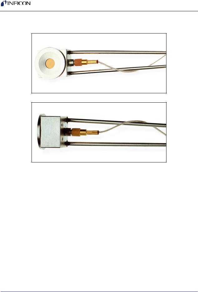
1.5 Front Load Single Sensors (PN SL-XXXXX)
Figure 1-4 Standard sensor
Figure 1-5 Right angle (compact) sensor
PN 074-156N
1 - 6

PN 074-156N
Front Load Single and Dual Sensors Operating Manual
1.5.1 Specifications
Maximum bakeout temperature
with no water . . . . . . . . . . . . . . . . . . . . . . . . . . . . . . 130°C
Maximum operating isothermal environment
temperature with minimum water flow . . . . . . . . . . . 400°C
Maximum sensor body
envelope without shutter . . . . . . . . . Standard Sensor
27.00 x 61.47 x 17.53 mm
(1.06 x 2.42 x 0.69 in.)
See Figure 1-6 on page 1-10.
Right Angle Sensor
28.19 x 26.92 x 26.92 mm
(1.11 x 1.06 x 1.06 in.)
See Figure 1-8 on page 1-12.
Water tube and
in-vacuum cable length . . . . . . . . . . Standard Length (E) 76.2 cm (30 in.) tubes,
3.175 mm (1/8 in.) OD seamless stainless steel, 0.406 mm (0.016 in.) wall thickness.
Includes 78.1 cm (30.75 in.) in-vacuum cable.
Extended Length (G)
121.9 cm (48 in.) tubes,
3.175 mm (1/8 in.) OD seamless stainless steel, 0.406 mm (0.016 in.) wall thickness.
Includes 152.4 cm (60 in.) in-vacuum cable.
Crystal exchange . . . . . . . . . . . . . . . Front-loading, self-contained package for ease of exchange
Mounting. . . . . . . . . . . . . . . . . . . . . . Two #4-40 tapped holes on the back of the sensor body
Crystal size. . . . . . . . . . . . . . . . . . . . 14 mm (0.550 in.) diameter
1 - 7

Front Load Single and Dual Sensors Operating Manual
1.5.2 Materials
Body and Holder . . . . . . . . . . . . . . . 304 stainless steel Springs, Electrical Contacts . . . . . . . Au plated Be-Cu Water Tubes. . . . . . . . . . . . . . . . . . . 304 stainless steel
In-Vacuum Cable . . . . . . . . . . . . . . . Silver coated copper, Teflon® insulated Electrical Connector . . . . . . . . . . . . . Glass insulated
Insulators . . . . . . . . . . . . . . . . . . . . . >99% Al2O3
Braze . . . . . . . . . . . . . . . . . . . . . . . . Vacuum process high temperature Ni-Cr alloy
1.5.3 Installation Requirements
Feedthrough. . . . . . . . . . . . . . . . . . . Without Shutter
Two pass water 4.8 mm (3/16 in.)
OD tubing with Microdot® coax connector (see section 1.8.3 on page 1-25)
With Shutter
Three pass tubes (two water and one air) 4.8 mm (3/16 in.) OD tubing with Microdot coax connector
(see section 1.8.3 on page 1-25)
Vacuum tight braze or weld joint or connectors for the water tubes
(welded connections or connections using Ultra-Torr® O-ring compression fittings may be provided by INFICON if sensor/feedthrough combination is ordered, see Figure 1-2 on page 1-4)
Other . . . . . . . . . . . . . . . . . . . . . . . . XIU or oscillator to match specific controller/monitor
The cable length from the crystal to the oscillator should not exceed 101.6 cm (40 in.) unless a ModeLock instrument is used. Refer to the controller/monitor
operating manual for cable length limitations.
SL-X1XXX only: Solenoid Valve for air, PN 750-420-G1
(see section 3.1 on page 3-1)
Water Flow Rate. . . . . . . . . . . . . . . . Minimum water flow 150 to 200 cm3/min, 30°C maximum
1 - 8
PN 074-156N
PN 074-156N
Front Load Single and Dual Sensors Operating Manual
Water Quality . . . . . . . . . . . . . . . . . . Coolant should not contain chlorides as stress corrosion cracking may occur. Extremely dirty water may result in loss of cooling capacity.
CAUTION
Do not allow water tubes to freeze. This may happen if the tubes pass through a cryogenic shroud and the flow of fluid is interrupted.
Air (SL-X1XXX only). . . . . . . . . . . . . 70 psi (gauge) {85 psi (absolute)}
(5.8 bar (absolute)) [584 kPa (absolute)] (minimum)
80 psi (gauge) {95 psi (absolute)}
(6.5 bar (absolute)) [653 kPa (absolute)] (maximum)
WARNING
Do not exceed 100 psi (gauge) {115 psi (absolute)} (7.9 bar (absolute)) [791 kPa (absolute)].
Connection to excessive pressure may result in personal injury or equipment damage.
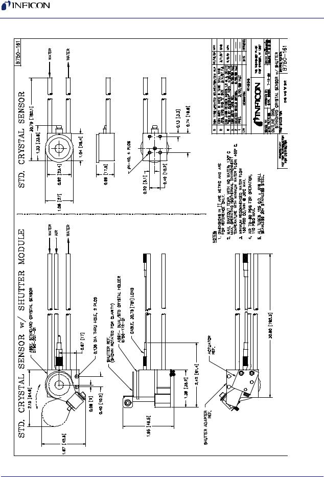
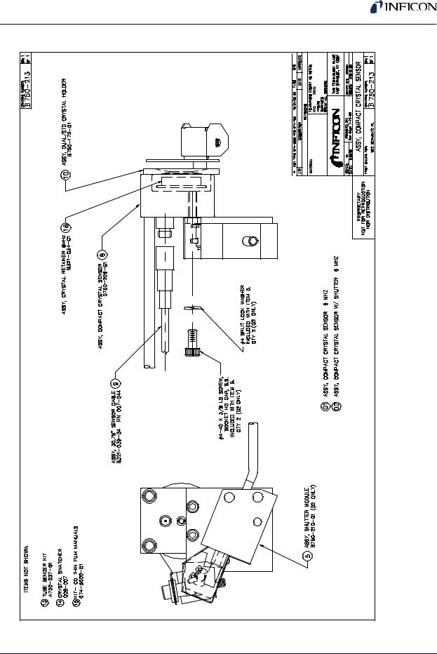
1.5.4 Single Sensor Drawings
The following Single Sensor Outline and Assembly Drawings provide dimensions and other relevant data necessary for planning equipment configurations.
Figure 1-6 . . . . . . Standard Crystal Sensor Outline
Figure 1-7 . . . . . . Standard Crystal Sensor Assembly (PN 750-211-GX) Figure 1-8 . . . . . .Right Angle Crystal Sensor Outline
Figure 1-9 . . . . . .Right Angle Crystal Sensor Assembly (PN 750-213-GX)
1 - 9
Front Load Single and Dual Sensors Operating Manual
U
Figure 6-1 crystalStandard outlinesensor
PN 156N-074
1 - 10
PN 074-156N
Front Load Single and Dual Sensors Operating Manual
Figure 1-7 PN 750-211-GX standard crystal sensor assembly
1 - 11

Front Load Single and Dual Sensors Operating Manual
1-8 Right angle crystal sensor outline |
Figure |
1 - 12 |
PN 074-156N
Front Load Single and Dual Sensors Operating Manual
PN 074-156N
, |
Figure 1-9 PN 750-213-GX right angle crystal sensor assembly
1 - 13
Front Load Single and Dual Sensors Operating Manual
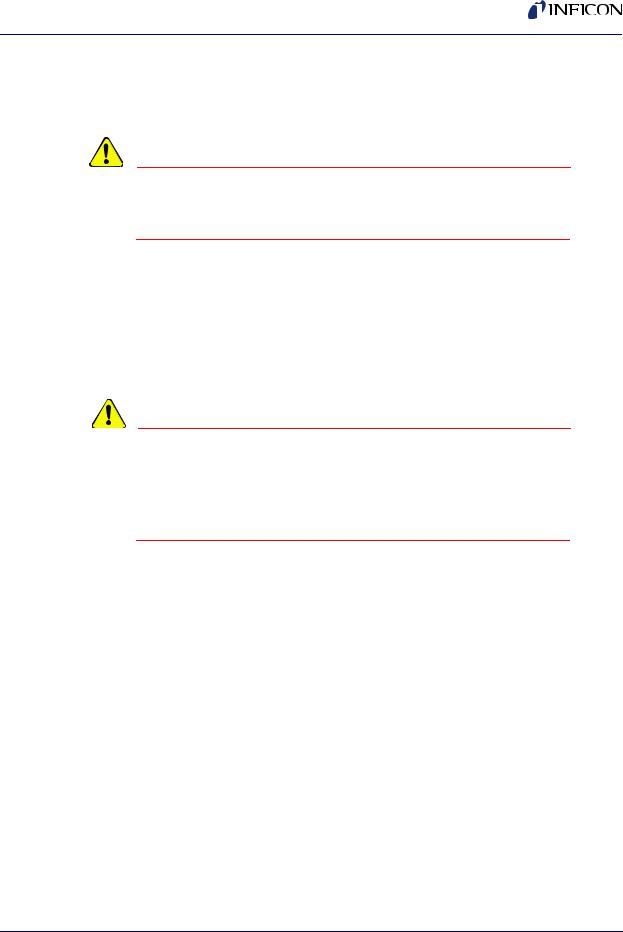
1.6 Front Load Dual Sensor (PN DL-AXXX)
Figure 1-10 Front Load Dual Sensor
Sensor 1 (Primary) |
Sensor 2 (Secondary) |
Sensor 1 |
Sensor 2
1.6.1 Specifications
Maximum bakeout temperature with no water . . . . . 130°C
Maximum operating isothermal environment
temperature with minimum water flow . . . . . . . . . . . 400°C
Maximum sensor body envelope . . . . . . . . . . . . . . . 39.12 x 82.04 x 49.54 mm (1.54 x 3.23 x 1.95 in.)
Water tube and
in-vacuum cable length . . . . . . . . . . Standard Length (E)
76.2 cm (30 in.) tubes, 3.175 mm (1/8 in.) OD seamless stainless steel, 0.406 mm
(0.016 in.) wall thickness.
Includes 78.1 cm (30.75 in.) in-vacuum cable.
Extended Length (G)
121.9 cm (48 in.) tubes,
3.175 mm (1/8 in.) OD seamless stainless steel, 0.406 mm (0.016 in.) wall thickness.
Includes 152.4 cm (60 in.) in-vacuum cable.
Crystal exchange . . . . . . . . . . . . . . . Front-loading, self-contained package for ease of exchange. Shutter flips up to ease access to the holders.
Mounting . . . . . . . . . . . . . . . . . . . . . Three #4-40 tapped holes Crystal size. . . . . . . . . . . . . . . . . . . . 14 mm (0.550 in.) diameter
PN 074-156N
1 - 14

PN 074-156N
Front Load Single and Dual Sensors Operating Manual
1.6.2 Materials
Body and Holder . . . . . . . . . . . . . . . 304 stainless steel Springs, Electrical Contacts . . . . . . . Au plated Be-Cu Water Tubes and Air Tube . . . . . . . . 304 stainless steel
In-Vacuum Cable . . . . . . . . . . . . . . . Silver coated copper, Teflon insulated Electrical Connector . . . . . . . . . . . . . Glass insulated
Insulators . . . . . . . . . . . . . . . . . . . . . >99% Al2O3
Other Mechanical Parts . . . . . . . . . . 304 or 18-8 stainless steel
Braze . . . . . . . . . . . . . . . . . . . . . . . . Vacuum process high temperature Ni-Cr alloy
1.6.3 Installation Requirements
Feedthrough . . . . . . . . . . . . . . . . . . . Three pass tubes (two water and one air) 4.8 mm (3/16 in.) OD tubing with two Microdot coax connectors
(see section 1.8.3 on page 1-25)
Vacuum tight braze or weld joint or connectors for the water tubes
(welded connections or connections using Ultra-Torr® O-ring compression fittings may be provided by INFICON if sensor/feedthrough combination is ordered, see Figure 1-3 on page 1-5)
Other . . . . . . . . . . . . . . . . . . . . . . . . Two XIUs or oscillators designed to interface with the deposition controller or one XIU or oscillator and one CrystalTwo switch
(not compatible with all controllers/monitors)
The cable length from the crystal to the oscillator should not exceed 101.6 cm (40 in.) unless a ModeLock instrument is used. Refer to the controller/monitor
operating manual for cable length limitations.
Solenoid valve assembly for air, PN 750-420-G1
(see section 3.1 on page 3-1)
Water Flow Rate. . . . . . . . . . . . . . . . Minimum water flow 150 to 200 cm3/min, 30°C maximum
1 - 15
Front Load Single and Dual Sensors Operating Manual
Water Quality . . . . . . . . . . . . . . . . . . Coolant should not contain chlorides as stress corrosion cracking may occur. Extremely dirty water may result in loss of cooling capacity.
CAUTION
Do not allow water tubes to freeze. This may happen if the tubes pass through a cryogenic shroud and the flow of fluid is interrupted.
Air Pressure . . . . . . . . . . . . . . . . . . . 70 psi (gauge) {85 psi (absolute)}
(5.8 bar (absolute)) [584 kPa (absolute)] (minimum)
80 psi (gauge) {95 psi (absolute)}
(6.5 bar (absolute)) [653 kPa (absolute)] (maximum)
WARNING
Do not exceed 100 psi (gauge) {115 psi (absolute)} (7.9 bar (absolute)] [791 kPa (absolute)].
Connection to excessive pressure may result in personal injury or equipment damage.
1.6.4 Dual Sensor Drawings
The following Dual Sensor Outline and Assembly Drawings provide dimensions and other relevant data necessary for planning equipment configurations.
Figure 1-11. . . . . Dual Crystal Sensor Outline
Figure 1-12. . . . . Dual Crystal Sensor Assembly (PN 750-212-GX)
1 - 16
PN 074-156N

Front Load Single and Dual Sensors Operating Manual
Figure 1-11 Dual crystal sensor outline
PN 074-156N
1 - 17
Loading...