


O P E R A T I N G M A N U A L
SQM-160™
Multi-Film Rate/Thickness Monitor
IPN 074-511-P1C

O P E R A T I N G M A N U A L
SQM-160™
Multi-Film Rate/Thickness Monitor
IPN 074-511-P1C


 ®
®
www.inficon.com reachus@inficon.com
©2012 INFICON
Trademarks
The trademarks of the products mentioned in this manual are held by the companies that produce them.
SQM-160™ and INFICON® is a trademark of INFICON GmbH.
Visual Basic®, Windows® and Microsoft® are registered trademarks of Microsoft Corporation.
Oracle® and Java® are registered trademarks of Oracle and/or its affiliates.
All other brand and product names are trademarks or registered trademarks of their respective companies.
Disclaimer
The information contained in this manual is believed to be accurate and reliable. However, INFICON assumes no responsibility for its use and shall not be liable for any special, incidental, or consequential damages related to the use of this product.
Due to our continuing program of product improvements, specifications are subject to change without notice.
Copyright
©2012 All rights reserved.
Reproduction or adaptation of any part of this document without permission is unlawful.


Warranty
WARRANTY AND LIABILITY - LIMITATION: Seller warrants the products manufactured by it, or by an affiliated company and sold by it, and described on the reverse hereof, to be, for the period of warranty coverage specified below, free from defects of materials or workmanship under normal proper use and service. The period of warranty coverage is specified for the respective products in the respective Seller instruction manuals for those products but shall not be less than one (1) year from the date of shipment thereof by Seller. Seller's liability under this warranty is limited to such of the above products or parts thereof as are returned, transportation prepaid, to Seller's plant, not later than thirty (30) days after the expiration of the period of warranty coverage in respect thereof and are found by Seller's examination to have failed to function properly because of defective workmanship or materials and not because of improper installation or misuse and is limited to, at Seller's election, either (a) repairing and returning the product or part thereof, or (b) furnishing a replacement product or part thereof, transportation prepaid by Seller in either case. In the event Buyer discovers or learns that a product does not conform to warranty, Buyer shall immediately notify Seller in writing of such non-conformity, specifying in reasonable detail the nature of such non-conformity. If Seller is not provided with such written notification, Seller shall not be liable for any further damages which could have been avoided if Seller had been provided with immediate written notification.
THIS WARRANTY IS MADE AND ACCEPTED IN LIEU OF ALL OTHER WARRANTIES, EXPRESS OR IMPLIED, WHETHER OF MERCHANTABILITY OR OF FITNESS FOR A PARTICULAR PURPOSE OR OTHERWISE, AS BUYER'S EXCLUSIVE REMEDY FOR ANY DEFECTS IN THE PRODUCTS TO BE SOLD HEREUNDER. All other obligations and liabilities of Seller, whether in contract or tort (including negligence) or otherwise, are expressly EXCLUDED. In no event shall Seller be liable for any costs, expenses or damages, whether direct or indirect, special, incidental, consequential, or other, on any claim of any defective product, in excess of the price paid by Buyer for the product plus return transportation charges prepaid.
No warranty is made by Seller of any Seller product which has been installed, used or operated contrary to Seller's written instruction manual or which has been subjected to misuse, negligence or accident or has been repaired or altered by anyone other than Seller or which has been used in a manner or for a purpose for which the Seller product was not designed nor against any defects due to plans or instructions supplied to Seller by or for Buyer.
This manual is intended for private use by INFICON® Inc. and its customers. Contact INFICON before reproducing its contents.
NOTE: These instructions do not provide for every contingency that may arise in connection with the installation, operation or maintenance of this equipment. Should you require further assistance, please contact INFICON.
www.inficon.com reachus@inficon.com

IPN 074-511-P1C
SQM-160 Operating Manual
Table Of Contents
Trademarks
Disclaimer
Copyright
Chapter 1
Introduction
1.1 Introduction. . . . . . . . . . . . . . . . . . . . . . . . . . . . . . . . . . . . . . . . . . . . . . . . . . 1-1
1.1.1 Related Manuals. . . . . . . . . . . . . . . . . . . . . . . . . . . . . . . . . . . . . . . . . . . . . . 1-2
1.2 Instrument Safety . . . . . . . . . . . . . . . . . . . . . . . . . . . . . . . . . . . . . . . . . . . . . 1-2
1.2.1 Definition of Notes, Cautions and Warnings. . . . . . . . . . . . . . . . . . . . . . . . . 1-2
1.2.2 General Safety Information. . . . . . . . . . . . . . . . . . . . . . . . . . . . . . . . . . . . . . 1-3
1.2.3 Earth Ground . . . . . . . . . . . . . . . . . . . . . . . . . . . . . . . . . . . . . . . . . . . . . . . . 1-3
1.3 How To Contact INFICON . . . . . . . . . . . . . . . . . . . . . . . . . . . . . . . . . . . . . . 1-4
1.3.1 Returning Your SQM-160 . . . . . . . . . . . . . . . . . . . . . . . . . . . . . . . . . . . . . . . 1-5
1.4 Specifications . . . . . . . . . . . . . . . . . . . . . . . . . . . . . . . . . . . . . . . . . . . . . . . . 1-5
1.4.1 Measurement . . . . . . . . . . . . . . . . . . . . . . . . . . . . . . . . . . . . . . . . . . . . . . . . 1-5
1.4.2 Film Parameters . . . . . . . . . . . . . . . . . . . . . . . . . . . . . . . . . . . . . . . . . . . . . . 1-5
1.4.3 System Parameters . . . . . . . . . . . . . . . . . . . . . . . . . . . . . . . . . . . . . . . . . . . 1-6
1.4.4 Digital I/O . . . . . . . . . . . . . . . . . . . . . . . . . . . . . . . . . . . . . . . . . . . . . . . . . . . 1-6
1.4.5 General Specifications . . . . . . . . . . . . . . . . . . . . . . . . . . . . . . . . . . . . . . . . . 1-7
1.5 Unpacking and Inspection . . . . . . . . . . . . . . . . . . . . . . . . . . . . . . . . . . . . . . 1-8
1.6 Parts and Options Overview. . . . . . . . . . . . . . . . . . . . . . . . . . . . . . . . . . . . . 1-8
1.6.1 Base Configurations . . . . . . . . . . . . . . . . . . . . . . . . . . . . . . . . . . . . . . . . . . . 1-8
1.6.2 Accessories . . . . . . . . . . . . . . . . . . . . . . . . . . . . . . . . . . . . . . . . . . . . . . . . . 1-9
1.6.3 Sensors . . . . . . . . . . . . . . . . . . . . . . . . . . . . . . . . . . . . . . . . . . . . . . . . . . . . 1-9
Chapter 2
Quick Start
2.1 Introduction. . . . . . . . . . . . . . . . . . . . . . . . . . . . . . . . . . . . . . . . . . . . . . . . . . 2-1
2.2 Installation . . . . . . . . . . . . . . . . . . . . . . . . . . . . . . . . . . . . . . . . . . . . . . . . . . 2-1
2.3 Front Panel . . . . . . . . . . . . . . . . . . . . . . . . . . . . . . . . . . . . . . . . . . . . . . . . . . 2-2
2.4 Rear Panel . . . . . . . . . . . . . . . . . . . . . . . . . . . . . . . . . . . . . . . . . . . . . . . . . . 2-3
2.5 System Connections. . . . . . . . . . . . . . . . . . . . . . . . . . . . . . . . . . . . . . . . . . . 2-4
2.6 Film Setup . . . . . . . . . . . . . . . . . . . . . . . . . . . . . . . . . . . . . . . . . . . . . . . . . . 2-6
2.7 Depositing a Film . . . . . . . . . . . . . . . . . . . . . . . . . . . . . . . . . . . . . . . . . . . . . 2-7
TOC - 1

SQM-160 Operating Manual
Chapter 3
Operation
3.1 Introduction. . . . . . . . . . . . . . . . . . . . . . . . . . . . . . . . . . . . . . . . . . . . . . . . . . 3-1
3.2 Menu Selection. . . . . . . . . . . . . . . . . . . . . . . . . . . . . . . . . . . . . . . . . . . . . . . 3-1
3.3 Film Menu. . . . . . . . . . . . . . . . . . . . . . . . . . . . . . . . . . . . . . . . . . . . . . . . . . . 3-2
3.4 System Menu . . . . . . . . . . . . . . . . . . . . . . . . . . . . . . . . . . . . . . . . . . . . . . . . 3-4
3.5 Sensor Selection . . . . . . . . . . . . . . . . . . . . . . . . . . . . . . . . . . . . . . . . . . . . . 3-6
3.6 Sensor Frequency . . . . . . . . . . . . . . . . . . . . . . . . . . . . . . . . . . . . . . . . . . . . 3-7
3.7 Sensor Tooling . . . . . . . . . . . . . . . . . . . . . . . . . . . . . . . . . . . . . . . . . . . . . . . 3-8
3.8 Display Units . . . . . . . . . . . . . . . . . . . . . . . . . . . . . . . . . . . . . . . . . . . . . . . . 3-9
3.9 Crystal Life . . . . . . . . . . . . . . . . . . . . . . . . . . . . . . . . . . . . . . . . . . . . . . . . . . 3-9
3.10 Zero Thickness. . . . . . . . . . . . . . . . . . . . . . . . . . . . . . . . . . . . . . . . . . . . . . . 3-9
3.11 Shutter Operation . . . . . . . . . . . . . . . . . . . . . . . . . . . . . . . . . . . . . . . . . . . . 3-10
3.12 Dual Sensors . . . . . . . . . . . . . . . . . . . . . . . . . . . . . . . . . . . . . . . . . . . . . . . 3-10
3.13 Rate Sampling . . . . . . . . . . . . . . . . . . . . . . . . . . . . . . . . . . . . . . . . . . . . . . 3-11
3.14 Time Setpoint . . . . . . . . . . . . . . . . . . . . . . . . . . . . . . . . . . . . . . . . . . . . . . . 3-12
3.15 Thickness Setpoint . . . . . . . . . . . . . . . . . . . . . . . . . . . . . . . . . . . . . . . . . . . 3-13
3.16 Simulate Mode . . . . . . . . . . . . . . . . . . . . . . . . . . . . . . . . . . . . . . . . . . . . . . 3-14
3.17 Defaulting the Memory . . . . . . . . . . . . . . . . . . . . . . . . . . . . . . . . . . . . . . . . 3-14
3.18 Relay Operation . . . . . . . . . . . . . . . . . . . . . . . . . . . . . . . . . . . . . . . . . . . . . 3-15
3.19 Analog Output Configuration . . . . . . . . . . . . . . . . . . . . . . . . . . . . . . . . . . . 3-16
3.20 I/O Connections . . . . . . . . . . . . . . . . . . . . . . . . . . . . . . . . . . . . . . . . . . . . . 3-16
3.21 Rack Mounting Procedure . . . . . . . . . . . . . . . . . . . . . . . . . . . . . . . . . . . . . 3-18
Chapter 4
SQM-160 Comm Software
4.1 Introduction. . . . . . . . . . . . . . . . . . . . . . . . . . . . . . . . . . . . . . . . . . . . . . . . . . 4-1
4.2 Installation . . . . . . . . . . . . . . . . . . . . . . . . . . . . . . . . . . . . . . . . . . . . . . . . . . 4-1
4.3 Main Window . . . . . . . . . . . . . . . . . . . . . . . . . . . . . . . . . . . . . . . . . . . . . . . . 4-2
4.4 Data Log Menu. . . . . . . . . . . . . . . . . . . . . . . . . . . . . . . . . . . . . . . . . . . . . . . 4-4
4.5 Films Menu. . . . . . . . . . . . . . . . . . . . . . . . . . . . . . . . . . . . . . . . . . . . . . . . . . 4-6
4.6 System Menu . . . . . . . . . . . . . . . . . . . . . . . . . . . . . . . . . . . . . . . . . . . . . . . . 4-8
4.7 Communications Menu. . . . . . . . . . . . . . . . . . . . . . . . . . . . . . . . . . . . . . . . . 4-9
4.8 Graph Options . . . . . . . . . . . . . . . . . . . . . . . . . . . . . . . . . . . . . . . . . . . . . . 4-10
4.9 Help Menu . . . . . . . . . . . . . . . . . . . . . . . . . . . . . . . . . . . . . . . . . . . . . . . . . 4-11
Chapter 5
Communications
5.1 Introduction. . . . . . . . . . . . . . . . . . . . . . . . . . . . . . . . . . . . . . . . . . . . . . . . . . 5-1
5.1.1 RS-232C Serial Port. . . . . . . . . . . . . . . . . . . . . . . . . . . . . . . . . . . . . . . . . . . 5-1
5.1.2 USB Port . . . . . . . . . . . . . . . . . . . . . . . . . . . . . . . . . . . . . . . . . . . . . . . . . . . 5-1
TOC - 2
IPN 074-511-P1C
IPN 074-511-P1C
SQM-160 Operating Manual
5.1.3 TCP/IP Ethernet Port . . . . . . . . . . . . . . . . . . . . . . . . . . . . . . . . . . . . . . . . . . 5-2 5.1.3.1 How to Set Up the Network Protocol on the PC . . . . . . . . . . . . . . . . . . . . . . 5-2 5.1.3.2 How to change the IP address of the SQM-160 . . . . . . . . . . . . . . . . . . . . . . 5-5 5.2 SQM-160 Comm Software . . . . . . . . . . . . . . . . . . . . . . . . . . . . . . . . . . . . . . 5-5 5.3 SQM-160 Communications Protocol . . . . . . . . . . . . . . . . . . . . . . . . . . . . . . 5-6 5.4 Commands . . . . . . . . . . . . . . . . . . . . . . . . . . . . . . . . . . . . . . . . . . . . . . . . . . 5-7 5.4.1 Command: @ . . . . . . . . . . . . . . . . . . . . . . . . . . . . . . . . . . . . . . . . . . . . . . . . 5-7 5.4.2 Command: A. . . . . . . . . . . . . . . . . . . . . . . . . . . . . . . . . . . . . . . . . . . . . . . . . 5-7 5.4.3 Command: B. . . . . . . . . . . . . . . . . . . . . . . . . . . . . . . . . . . . . . . . . . . . . . . . . 5-8 5.4.4 Command: C . . . . . . . . . . . . . . . . . . . . . . . . . . . . . . . . . . . . . . . . . . . . . . . . 5-8 5.4.5 Command: D . . . . . . . . . . . . . . . . . . . . . . . . . . . . . . . . . . . . . . . . . . . . . . . . 5-9 5.4.6 Command: J . . . . . . . . . . . . . . . . . . . . . . . . . . . . . . . . . . . . . . . . . . . . . . . . . 5-9 5.4.7 Command: L . . . . . . . . . . . . . . . . . . . . . . . . . . . . . . . . . . . . . . . . . . . . . . . . . 5-9 5.4.8 Command: M . . . . . . . . . . . . . . . . . . . . . . . . . . . . . . . . . . . . . . . . . . . . . . . . 5-9 5.4.9 Command: N . . . . . . . . . . . . . . . . . . . . . . . . . . . . . . . . . . . . . . . . . . . . . . . . 5-9 5.4.10 Command: O . . . . . . . . . . . . . . . . . . . . . . . . . . . . . . . . . . . . . . . . . . . . . . . . 5-9 5.4.11 Command: P. . . . . . . . . . . . . . . . . . . . . . . . . . . . . . . . . . . . . . . . . . . . . . . . 5-10 5.4.12 Command: R . . . . . . . . . . . . . . . . . . . . . . . . . . . . . . . . . . . . . . . . . . . . . . . 5-10 5.4.13 Command: S. . . . . . . . . . . . . . . . . . . . . . . . . . . . . . . . . . . . . . . . . . . . . . . . 5-10 5.4.14 Command: T. . . . . . . . . . . . . . . . . . . . . . . . . . . . . . . . . . . . . . . . . . . . . . .T5-10 5.4.15 Command: U . . . . . . . . . . . . . . . . . . . . . . . . . . . . . . . . . . . . . . . . . . . . . . . 5-10 5.4.16 Command: W . . . . . . . . . . . . . . . . . . . . . . . . . . . . . . . . . . . . . . . . . . . . . . . 5-11 5.4.17 Command: Y. . . . . . . . . . . . . . . . . . . . . . . . . . . . . . . . . . . . . . . . . . . . . . . . 5-11 5.4.18 Command: Z. . . . . . . . . . . . . . . . . . . . . . . . . . . . . . . . . . . . . . . . . . . . . . . . 5-11 5.5 CRC Examples . . . . . . . . . . . . . . . . . . . . . . . . . . . . . . . . . . . . . . . . . . . . . . 5-12 5.5.1 Visual Basic® 5/6 . . . . . . . . . . . . . . . . . . . . . . . . . . . . . . . . . . . . . . . . . . . . 5-12 5.5.2 Java® . . . . . . . . . . . . . . . . . . . . . . . . . . . . . . . . . . . . . . . . . . . . . . . . . . . . . 5-14 5.5.3 C++. . . . . . . . . . . . . . . . . . . . . . . . . . . . . . . . . . . . . . . . . . . . . . . . . . . . . . . 5-14
Chapter 6
Troubleshooting and Maintenance
6.1 Troubleshooting Guide . . . . . . . . . . . . . . . . . . . . . . . . . . . . . . . . . . . . . . . . . 6-1
6.2 Troubleshooting . . . . . . . . . . . . . . . . . . . . . . . . . . . . . . . . . . . . . . . . . . . . . . 6-2
6.2.1 Troubleshooting the SQM-160 . . . . . . . . . . . . . . . . . . . . . . . . . . . . . . . . . . . 6-2
6.2.2 Troubleshooting Sensors . . . . . . . . . . . . . . . . . . . . . . . . . . . . . . . . . . . . . . . 6-3
6.2.3 Troubleshooting Computer Communications . . . . . . . . . . . . . . . . . . . . . . . . 6-8
6.3 Replacing the Crystal . . . . . . . . . . . . . . . . . . . . . . . . . . . . . . . . . . . . . . . . . . 6-8
6.3.1 Front Load . . . . . . . . . . . . . . . . . . . . . . . . . . . . . . . . . . . . . . . . . . . . . . . . . . 6-9
6.3.2 Cool Drawer . . . . . . . . . . . . . . . . . . . . . . . . . . . . . . . . . . . . . . . . . . . . . . . . 6-10
6.3.3 Bakeable Sensor . . . . . . . . . . . . . . . . . . . . . . . . . . . . . . . . . . . . . . . . . . . . 6-12
TOC - 3

SQM-160 Operating Manual
6.3.4 Sputtering Sensor. . . . . . . . . . . . . . . . . . . . . . . . . . . . . . . . . . . . . . . . . . . . 6-13
6.3.5 Crystal Snatcher. . . . . . . . . . . . . . . . . . . . . . . . . . . . . . . . . . . . . . . . . . . . . 6-14
6.4Crystal Sensor Emulator
IPN 760-601-G2 . . . . . . . . . . . . . . . . . . . . . . . . . . . . . . . . . . . . . . . . . . . . . 6-15
6.4.1 Diagnostic Procedures . . . . . . . . . . . . . . . . . . . . . . . . . . . . . . . . . . . . . . . . 6-16
6.4.1.1 Measurement System Diagnostic Procedure . . . . . . . . . . . . . . . . . . . . . . . 6-16
6.4.1.2Feedthrough Or In-Vacuum Cable
Diagnostic Procedure . . . . . . . . . . . . . . . . . . . . . . . . . . . . . . . . . . . . . . . . . 6-17
6.4.1.3Sensor Head Or Monitor Crystal
Diagnostic Procedure . . . . . . . . . . . . . . . . . . . . . . . . . . . . . . . . . . . . . . . . . 6-18
6.4.1.4System Diagnostics Pass But
Crystal Fail Message Remains. . . . . . . . . . . . . . . . . . . . . . . . . . . . . . . . . . 6-19
6.4.2 Sensor Cover Connection . . . . . . . . . . . . . . . . . . . . . . . . . . . . . . . . . . . . . 6-20
6.4.2.1 Compatible Sensor Heads . . . . . . . . . . . . . . . . . . . . . . . . . . . . . . . . . . . . . 6-20
6.4.2.2 Incompatible Sensor Heads . . . . . . . . . . . . . . . . . . . . . . . . . . . . . . . . . . . . 6-20
6.4.3 Emulator Specifications . . . . . . . . . . . . . . . . . . . . . . . . . . . . . . . . . . . . . . . 6-21
Chapter 7
Calibration Procedures
7.1 Importance of Density, Tooling and Z-Ratio. . . . . . . . . . . . . . . . . . . . . . . . . 7-1
7.2 Determining Density . . . . . . . . . . . . . . . . . . . . . . . . . . . . . . . . . . . . . . . . . . . 7-1
7.3 Determining Tooling . . . . . . . . . . . . . . . . . . . . . . . . . . . . . . . . . . . . . . . . . . . 7-2
7.4 Laboratory Determination of Z-Ratio . . . . . . . . . . . . . . . . . . . . . . . . . . . . . . 7-2
Chapter 8
Measurement and Theory
8.1 Basics. . . . . . . . . . . . . . . . . . . . . . . . . . . . . . . . . . . . . . . . . . . . . . . . . . . . . . 8-1
8.1.1 Monitor Crystals . . . . . . . . . . . . . . . . . . . . . . . . . . . . . . . . . . . . . . . . . . . . . . 8-2
8.1.2 Period Measurement Technique . . . . . . . . . . . . . . . . . . . . . . . . . . . . . . . . . 8-4
8.1.3 Z-match Technique . . . . . . . . . . . . . . . . . . . . . . . . . . . . . . . . . . . . . . . . . . . 8-5
8.1.4 Active Oscillator . . . . . . . . . . . . . . . . . . . . . . . . . . . . . . . . . . . . . . . . . . . . . . 8-6
Appendix A
Material Table
A.1 Introduction. . . . . . . . . . . . . . . . . . . . . . . . . . . . . . . . . . . . . . . . . . . . . . . . . .A-1
IPN 074-511-P1C
TOC - 4
SQM-160 Operating Manual
Chapter 1
Introduction
1.1 Introduction
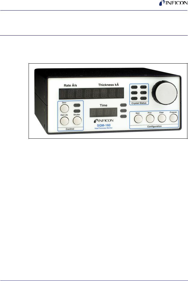
Figure 1-1 SQM-160 Multi-Film Rate/Thickness Monitor
IPN 074-511-P1C
The SQM-160™ uses proven INFICON® quartz crystal sensor technology to measure rate and thickness in a thin film deposition process. Two sensor inputs are standard and four additional sensor inputs are optional. Two recorder outputs provide analog rate and thickness signals.
Sensor inputs can be assigned to different materials, averaged for accurate deposition control in large systems, or configured for a dual sensor. The rate sampling mode allows a shuttered sensor to extend sensor life in high rate processes. Rate displays of 0.1 Å/s or 0.01 Å/s are user selectable. In addition, frequency or mass displays can be selected. Four relay outputs allow the SQM-160 to control source or sensor shutters, signal time and thickness setpoints, and signal crystal failure. Digital inputs allow external signals to start/stop and zero readings.
The SQM-160 comes with an RS-232 port and Windows® software that allows instrument setup from your computer. The software can be used to set and store all parameters, operate the instrument, and save process data in an .txt file that can easily be imported into Excel®. USB or Ethernet options add to the communications flexibility.
1 - 1
SQM-160 Operating Manual
1.1.1 Related Manuals
Sensors are covered in separate manuals. PDF files of these manuals are contained in the 074-5000-G1 CD, part of the Ship Kit.
074-154 - Bakeable Sensor
074-156 - Front Load Sensor, Single/Dual
074-157 - Sputtering Sensor
147-800 - Cool Drawer Sensor, Single/Dual
1.2Instrument Safety
1.2.1 Definition of Notes, Cautions and Warnings
When using this manual, please pay attention to the NOTES, CAUTIONS and WARNINGS found throughout. For the purposes of this manual they are defined as follows:
NOTE: Pertinent information that is useful in achieving maximum SQM-160 efficiency when followed.
CAUTION
Failure to heed these messages could result in damage to the SQM-160.
WARNING
Failure to heed these messages could result in personal injury.
WARNING - Risk Of Electric Shock
Dangerous voltages are present which could result in personal injury.
IPN 074-511-P1C
1 - 2
SQM-160 Operating Manual
1.2.2 General Safety Information
WARNING - Risk Of Electric Shock
Do not open the SQM-160 case! There are no user-serviceable components within the SQM-160 case.
Dangerous voltages may be present whenever the power cord or external input/relay connectors are present.
Refer all maintenance to qualified personnel.
CAUTION
This SQM-160 contains delicate circuitry which is susceptible to transient power line voltages. Disconnect the line cord whenever making any interface connections. Refer all maintenance to qualified personnel.
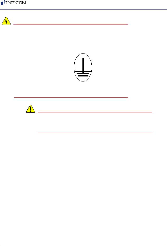
1.2.3 Earth Ground
The SQM-160 is connected to earth ground through a sealed three-core (three-conductor) power cable, which must be plugged into a socket outlet with a protective earth terminal. Extension cables must always have three conductors including a protective earth terminal.
IPN 074-511-P1C
1 - 3
SQM-160 Operating Manual
WARNING - Risk Of Electric Shock
Never interrupt the protective earth circuit.
Any interruption of the protective earth circuit inside or outside the SQM-160, or disconnection of the protective earth terminal is likely to make the SQM-160 dangerous.
This symbol indicates where the protective earth ground is connected inside the SQM-160. Never unscrew or loosen this connection.
WARNING
There are no adjustments or user-serviceable parts inside the SQM-160. For maintenance or repair, contact INFICON.
1.3 How To Contact INFICON
Worldwide support information, to contact a:
Technical Support Engineer with questions regarding applications for and programming the SQM-160
Service Engineer with questions regarding troubleshooting, diagnosing or repairing a defective SQM-160
Sales and Customer Service, to contact the INFICON Sales office nearest you
Repair Service, to contact the INFICON Service Center nearest you
is available at the Support tab a www.inficon.com.
If you are experiencing a problem with your SQM-160, please have the following information readily available:
the serial number and firmware version for your SQM-160,
a description of your problem,
an explanation of any corrective action that you may have already attempted,
and the exact wording of any error messages that you may have received. To contact Customer Support, see Support at www.inficon.com.
1 - 4
IPN 074-511-P1C

IPN 074-511-P1C
SQM-160 Operating Manual
1.3.1 Returning Your SQM-160
Do not return any component of your SQM-160 to INFICON without first speaking with a Customer Support Representative. You must obtain a Return Material Authorization (RMA) number from the Customer Support Representative.
If you deliver a package to INFICON without an RMA number, your package will be held and you will be contacted. This will result in delays in servicing your SQM-160.
Prior to being given an RMA number, you may be required to complete a Declaration Of Contamination (DOC) form if your sensor has been exposed to process materials. DOC forms must be approved by INFICON before an RMA number is issued. INFICON may require that the sensor be sent to a designated decontamination facility, not to the factory.
1.4 Specifications
1.4.1 Measurement
Number of Sensors . . . . . . . . . . . . . 2 standard, 4 additional optional Sensor Frequency Range . . . . . . . . 4.0 MHz to 6.0 MHz
Reference Frequency Accuracy . . . . 0.002%
Reference Frequency Stability . . . . . +/- 2ppm (total, 0 to 50°C) Thickness Display Resolution . . . . . 1 Å
Frequency Resolution* . . . . . . . . . . . +/- 0.12 Hz (Std.), +/- 0.03 Hz (HiRes) Rate Resolution* . . . . . . . . . . . . . . . 0.60 Å/s (Std.), 0.037 Å/s (HiRes) Thickness Resolution* . . . . . . . . . . . 0.15 Å (Std.), 0.037 Å (HiRes) *Density = 1, Period = 4 rdgs/sec (Std.) 10 rdgs/s (HiRes)
1.4.2 Film Parameters
Stored Films . . . . . . . . . . . . . . . . . . . 99
Density . . . . . . . . . . . . . . . . . . . . . . . 0.5 – 99.99 gm/cc Tooling . . . . . . . . . . . . . . . . . . . . . . . 10 – 399 % Z-Ratio . . . . . . . . . . . . . . . . . . . . . . . 0.10 – 10.00 Final Thickness . . . . . . . . . . . . . . . . 0.000 – 99.99 kÅ Thickness Setpoint . . . . . . . . . . . . . . 0.000 – 99.99 kÅ
Time Setpoint . . . . . . . . . . . . . . . . . . 0:00 – 99:59 mm:ss Sample/Hold. . . . . . . . . . . . . . . . . . . 0-9999 s
Sensor Average . . . . . . . . . . . . . . . . Any combination of installed sensors
1 - 5

SQM-160 Operating Manual
1.4.3 System Parameters
Measurement Period . . . . . . . . . . . . 0.15 to 2 s
Simulate Mode . . . . . . . . . . . . . . . . . On/Off
Frequency Mode . . . . . . . . . . . . . . . On/Off
Rate Resolution . . . . . . . . . . . . . . . . 0.01/0.1 Å/s
Measurement Filter . . . . . . . . . . . . . 1 to 20 readings
Dual Crystal 1/2 . . . . . . . . . . . . . . . . On/Off
Rate Sampling . . . . . . . . . . . . . . . . . On/Off
RS-232 Baud Rate . . . . . . . . . . . . . . 2.4/4.8/9.6/19.2 kb/s
Etch Mode . . . . . . . . . . . . . . . . . . . . On/Off
Crystal Tooling 1-6 . . . . . . . . . . . . . . 10-399%
Crystal Fail Min/Max. . . . . . . . . . . . . 4.0 to 6.0 MHz / 4.1 to 6.1 MHz
1.4.4 Digital I/O
Digital Inputs. . . . . . . . . . . . . . . . . . . 4
Functions . . . . . . . . . . . . . . . . . . . . . Open Shutter, Close Shutter, Zero Thickness, Zero Time
Input Rating . . . . . . . . . . . . . . . . . . . 5 V (dc), non-isolated Relay Outputs. . . . . . . . . . . . . . . . . . 4
Functions . . . . . . . . . . . . . . . . . . . . . Shutter, Sample/Hold or Thickness Setpoint, Dual Sensor Shutter or Time Setpoint, Crystal Fail
Relay Rating. . . . . . . . . . . . . . . . . . . 30 Vrms or 30 V (dc), 2 A maximum
IPN 074-511-P1C
1 - 6

SQM-160 Operating Manual
1.4.5 General Specifications
Mains Power Supply. . . . . . . . . . . . . 100-120/200-240~, ±10% nominal, 50/60 Hz Power Consumption . . . . . . . . . . . . . 20 W
Operating Environment . . . . . . . . . . 0°C to 50°C
0 to 80% RH non-condensing
0 to 2,000 meters Indoor Use Only
Class 1 Equipment (Grounded Type) Suitable for Continuous Operation Ordinary Protection (not protected against harmful ingress of moisture)
Pollution Degree 2
Installation (Overvoltage) Category II for transient overvoltages
Storage Environment . . . . . . . . . . . . -40°C to 70°C
Rack Dimensions (HxWxD) . . . . . . . 88.5 mm x 212.7 mm x 196.9 mm Weight . . . . . . . . . . . . . . . . . . . . . . . 2.7 kg (6 pounds)
IPN 074-511-P1C
1 - 7

SQM-160 Operating Manual
1.5 Unpacking and Inspection
1If the SQM-160 has not been removed from its packaging, do so now.
2Carefully examine the unit for damage that may have occurred during shipping. This is especially important if you notice obvious rough handling on the outside of the container. Immediately report any damage to the carrier and to INFICON.
3Do not discard the packing materials until you have taken inventory and have at least performed a power on verification.
4Take an inventory of your order by referring to your order invoice and the information contained in section 1.6.
5To install and setup, see Chapter 2, Quick Start.
6For additional information or technical assistance, contact INFICON, refer to section 1.3 on page 1-4.
1.6Parts and Options Overview
1.6.1 Base Configurations
SQM-160 . . . . . . . . . . . . . . . . . . . . . . . . .SQM160-X-X-X
Consult the figure below for possible configurations.
Figure 1-2 SQM-160 Configurations
IPN 074-511-P1C
Technical Manual . . . . . . . . . . . . . . . . . . .074-511 on 074-5000-G1 CD
1 - 8
IPN 074-511-P1C
SQM-160 Operating Manual
1.6.2 Accessories
Each sensor requires an oscillator kit to interface to the controller: SQM-160 10 ft. Oscillator Kit . . . . . . 782-934-003-10
SQM-160 25 ft. Oscillator Kit . . . . . . 782-934-003-25 SQM-160 50 ft. Oscillator Kit . . . . . . 782-934-003-50 SQM-160 100 ft. Oscillator Kit . . . . . 782-934-003-99
Above kits consist of oscillator 782-900-010, 6 inch BNC oscillator to feedthrough cable 782-902-011 and BNC controller to oscillator cable 782-902-012-10, 782-902-012-25, 782-902-012-50 or 782-902-012-99. These kits are designed for use with the standard in-vacuum cables ranging in length from 6 in. (15.2 cm) to 36 in. (91.4 cm). The 007-044 standard in-vacuum cable supplied with the front load style sensors are 30.75 in. (78.1 cm) long.
19 in. Rack mount for 1 SQM-160 . . 782-900-008 19 in. Rack mount for 2 SQM-160 . . 782-900-014
1.6.3 Sensors
Front Load Single Sensor. . . . . . . . . . . . . . . . . . . . . SL-XXXXX
Front Load Dual Sensor . . . . . . . . . . . . . . . . . . . . . . DL-AXXX Cool Drawer Single Sensor . . . . . . . . . . . . . . . . . . . CDS-XXFXX Cool Drawer Dual Sensor. . . . . . . . . . . . . . . . . . . . . CDD-XFXX Sputtering Sensor. . . . . . . . . . . . . . . . . . . . . . . . . . . 750-618-G1 Front Load UHV Bakeable Sensor . . . . . . . . . . . . . . BK-AXF
NOTE: "X" in part number indicates customer-selectable option, see www.inficon.com for Sensor Datasheets.
NOTE: All shuttered sensors require a feedthrough with an air line and a pneumatic shutter actuator control valve.
Pneumatic Shutter Actuator Control Valve . . . . . . . . 750-420-G1
NOTE: Multi-crystal (rotary) sensor should not be used with the SQM-160
1 - 9

SQM-160 Operating Manual
This page is intentionally blank.
IPN 074-511-P1C
1 - 10
IPN 074-511-P1C
SQM-160 Operating Manual
Chapter 2
Quick Start
2.1 Introduction
This section assumes you are familiar with thin film monitors. See section 2.3, Front Panel, on page 2-2 and section 2.4, Rear Panel, on page 2-3 for basic system use and connection information.
2.2 Installation
WARNING - Risk Of Electric Shock
Maintain adequate insulation and physical separation of sensor, I/O, and wiring from hazardous voltages.
1Rack Installation
The SQM-160 occupies a 3.5 in. high, half-rack space. Rack installation requires an optional half-rack adapter kit or a full rack extender kit. Install the SQM-160 in a 19 in. rack with the appropriate hardware. See section 3.21, Rack Mounting Procedure, on page 3-18, for detailed installation instructions.
2Power Connection
WARNING - Risk Of Electric Shock
Verify that the power cable provided is connected to a properly grounded mains receptacle.
3Sensor Connections
Connect the BNC cables and oscillator from your vacuum chamber feedthrough to the SQM-160 Sensor Input(s). See section 2.4 on page 2-3.
4Digital I/O Connections
Refer to section 3.20, I/O Connections, on page 3-16 for details on wiring digital I/O to the SQM-160 Relay I/O connector.
5Computer Connection
If you would like to use the supplied Windows Comm software with the SQM-160, see section Chapter 4, SQM-160 Comm Software, on page 4-1.
2 - 1
SQM-160 Operating Manual
6Option Connections
If you have purchased the optional four sensor card, connect the four additional sensors to these four inputs.
7Power On
Move the rear panel power switch to the On (|) position. The SQM-160 will briefly display its software and hardware versions, then go to normal operating mode.
2.3Front Panel
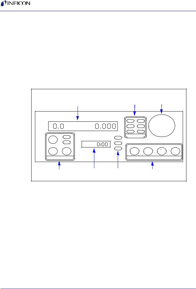
Figure 2-1 SQM-160 Front Panel |
|
|
|
|
||
|
|
|
Crystal |
Control |
|
|
|
|
|
Status |
|
||
|
Display 1 |
LEDs |
Knob |
|
||
Rate A/s |
Thickness kA |
1 |
2 |
|
|
|
|
|
|
3 |
4 |
|
|
|
|
|
5 |
6 |
|
|
Zero |
Open |
|
Crystal Status |
|
|
|
|
Time |
|
|
|||
|
Time SP |
|
|
|
||
|
|
|
|
|
||
|
Closed |
|
|
|
|
|
|
|
Thk SP |
|
|
|
|
Xtal Life |
Shutter |
|
Next |
Prev |
Clear |
Program |
|
|
|
Final Thk |
|
|
|
Control |
|
|
Configuration |
|
||
Control |
Display 2 |
Setpoint |
Configuration |
|
||
Section |
|
LEDs |
Section |
|
||
Display 1
Displays rate/thickness or frequency in normal operation. If multiple sensors are being used and Display shows Time, this is the average of those sensors. Turn the Control Knob right to display each individual sensor's readings. Displays the setup parameter name in program mode.
Display 2
Displays deposition time, or the sensor # displayed on Display 1 when scrolling through sensor readings. Displays setup parameter values in program mode.
Control Section
Push-button to zero the thickness reading.
Push-button to toggle display between Crystal Life and Rate/Thickness readings. Push-button to Open/Close shutter relay.
Two LED shutter relay status display.
2 - 2
IPN 074-511-P1C
SQM-160 Operating Manual
Configuration Section
Push-button to enter/exit program mode.
Push-button to cancel a change and return to original value.
Push-buttons to move to Next/Previous parameter.
Setpoint LEDs
Illuminates when the indicated setpoint is reached.
Crystal Status LEDs
Illuminates when the crystal is active and operating properly.
Flashes when an active crystal fails.
Extinguished when that crystal is not being used.
Control Knob
Used to adjust values or scroll though menu selections.
Pushing the control knob stores the current setting.
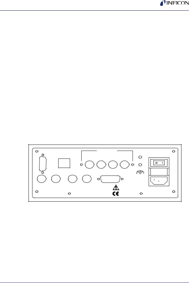
2.4 Rear Panel |
|
|
|
|
|
|
|
Figure 2-2 |
Rear Panel |
|
|
|
|
|
|
RS-232 |
USB/Ethernet |
|
Option Card |
|
|||
|
Sensor |
Fuse T2.5A 250V |
|||||
|
|
|
|
|
|||
|
|
|
|
3 |
4 |
5 |
6 |
Sensor 1 |
Sensor 2 |
Rate Out |
Thick Out |
|
Relay I/O |
|
|
P1C |
|
|
|
|
|
|
100-120/200-240V~ |
511- |
|
|
|
|
|
|
50/60 Hz |
|
|
|
|
|
|
20 W |
|
074- |
|
|
|
|
|
|
|
|
|
|
|
|
|
|
|
IPN |
|
|
|
|
|
|
|
Sensor 1 & 2 |
|
|
|
|
|
||
Connection to quartz crystal sensors. See section 2.5 on page 2-4 for detailed hookup information.
Rate and Thick Outputs
Provides 0-5 V analog outputs for Sensor 1 & 2 rate and thickness readings. For connection to strip chart recorders, etc.
Relay I/O
Connects 4 relays and 4 digital inputs to external devices. See section 3.20, I/O Connections, on page 3-16 for connections.
2 - 3

SQM-160 Operating Manual
RS-232
Connection to computer for programming and data acquisition. See Chapter 5, Communications.
USB/Ethernet
Optional connection to computer USB or Ethernet port for programming and data acquisition. See Chapter 5, Communications.
Option Card
Provides four additional sensor measurement channels.
Measurement ground terminal useful for common system and cable grounding.
Power Connector
WARNING
Use removable power cords only of the specified type and rating, attached to a properly grounded receptacle.
2.5 System Connections
Figure 2-3 shows typical vacuum system wiring.
WARNING - Risk Of Electric Shock
WARNING: Maintain adequate insulation and physical separation of sensor wiring from hazardous voltages.
2 - 4
IPN 074-511-P1C
IPN 074-511-P1C
SQM-160 Operating Manual
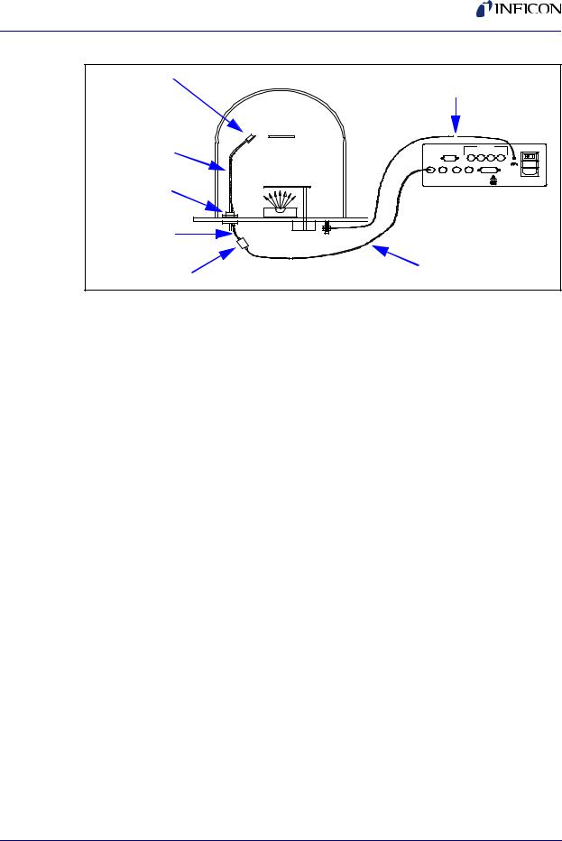
Figure 2-3 Typical Vacuum System Wiring
Sensor |
Ground Wire |
|
|||
|
|
||||
In-Vac Cable |
|
|
Option Card |
|
|
|
|
Sensor |
Fuse T2.5A 250V |
||
RS-232 |
3 |
4 5 |
6 |
||
|
|
|
|
||
|
Sensor 1 Sensor 2 Rate Out Thick Out |
Relay I/O |
|
||
|
|
|
|
100-120/200-240V~ |
|
|
|
|
|
50/60 Hz |
|
Feedthrough |
|
|
|
20 W |
|
SQM-160 Monitor |
|||||
|
|||||
6 in. BNC Cable |
|
|
|
|
|
Oscillator |
10 ft. BNC Cable |
||||
|
|
|
|
||
Sensor |
|
|
|
|
|
Holds the quartz crystal used to measure rate and thickness. Crystals must be replaced occasionally.
In-Vac Cable
Microdot cable that connects the sensor to the feedthrough.
Feedthrough
Provides isolation between vacuum and atmosphere for electrical and cooling lines.
6 in. BNC Cable
Provides a flexible connection from the feedthrough to the oscillator. Keep this cable as short as possible.
Oscillator
Contains the electronics to operate the quartz crystal. The length from the oscillator to the crystal should be under 40 in. (1 m).
10' BNC Cable
Connects the oscillator to the SQM-160. Lengths up to 100 ft. (30 m) are acceptable.
Ground Wire
A wire, preferably braided, that connects the vacuum system to the SQM-160 ground terminal.
2 - 5

SQM-160 Operating Manual
2.6 Film Setup
This section will help you set up the SQM-160 to measure a film. See Chapter 3, Operation, for detailed programming instructions.
1Enter Program Mode
Press Program to enter the film setup menu. If the Crystal Life display is shown, press Xtal Life to return to Rate/Thickness mode, then press Program.
2Select a Film
Turn the Control Knob to select one of the 99 possible films, then press the Control Knob to enter that Film Menu.
3Set Film Parameters
Turn the Control Knob to set the first film parameter (Density). The parameter value is shown in Display 2. Press the Control Knob to save the value and move to the next parameter. Press Clear to return the film parameter to its original value. Continue to set each parameter. Be sure to press the Control Knob to store each parameter. Press Program to exit Program mode and return to normal mode.
4Set System Parameters
To Enter the System Menu, press Program, then Prev. Select and set system parameters by turning and then pressing the Control Knob as described above. Press Program to return to Normal mode.
If the sensor(s) selected during Film setup are connected properly to the SQM-160, the Crystal Status LEDs should be illuminated. If not, return to the Film Menu and set the Sensor Average parameter to the desired sensor(s). See section 3.5 on page 3-6 for detailed information on assigning sensors to a film.
If the Crystal Status LED is flashing, the sensor is most likely not properly connected. A small test crystal, supplied with each oscillator module, can be used to test sensor connections external to the vacuum chamber. To use the test crystal, disconnect the oscillator from its 6 in. BNC cable. Attach the test crystal to the oscillator's feedthrough connector. The Crystal Status LED will remain illuminated if the external sensor connections are correct.
See section 6.2.2, Troubleshooting Sensors, on page 6-3 for assistance in troubleshooting sensor problems.
IPN 074-511-P1C
2 - 6

IPN 074-511-P1C
SQM-160 Operating Manual
2.7 Depositing a Film
If you have followed this Quick Start chapter, you are ready to deposit a film. Follow the procedure below to begin deposition.
1Verify Sensor Operation
Verify that the Crystal Status LED for the measuring sensor(s) is illuminated, and not blinking.
2Display Rate/Thickness
Display 1 should be displaying Rate on the left and Thickness on the right. If the Crystal Life display mode is active, press the Xtal Life switch to return to Rate/Thickness mode. If the Program Mode is active, press Program to return to normal mode.
3Zero Thickness
If needed, press the Zero switch to zero the thickness reading.
4Start Deposition
Apply power to the source evaporation supply. If the SQM-160 shutter relay is connected, press the Shutter switch to open the source shutter and begin deposition.
Rate and Thickness displays should begin to move from zero.
If the displays remain at zero, check the system setup to assure that evaporating is actually taking place. Also check that the deposited material is reaching the sensor.
If the display is erratic or noisy, first check your sensor connections. See section 6.2.2, Troubleshooting Sensors, on page 6-3 for information that can help in identifying the cause of noisy readings.
If the rate and thickness readings do not match expectations, see the Film Parameter (Density, Z-Ratio (Z-Factor), Tooling) and Sensor Tooling sections of Chapter 3.
Review the remainder of this manual for detailed operational, programming, and safety information.
2 - 7

SQM-160 Operating Manual
This page is intentionally blank.
IPN 074-511-P1C
2 - 8
 Loading...