


 Loading...
Cover Page
O P E R A T I N G M A N U A L
Transpector® XPR 3+
Gas Analysis System
PN 074-687-P1A

Trademarks
The trademarks of the products mentioned in this manual are held by the companies that produce them.
INFICON®, Transpector® and FabGuard® are registered trademarks of INFICON GmbH. Windows®, and Microsoft® are registered trademarks of Microsoft Corporation.
All other brand names, product names or trademarks belong to their respective holders.
Software Copyrights
This product contains embedded software protected under the following copyrights: Copyright INFICON Inc.
Disclaimer
The information contained in this Operating Manual is believed to be accurate and reliable. However, INFICON assumes no responsibility for its use and shall not be liable for any special, incidental, or consequential damages related to the use of this product.
Due to our continuing program of product improvements, specifications are subject to change without notice.
Copyright
©2017 All rights reserved.
Reproduction or adaptation of any part of this document without permission is unlawful.

Transpector XPR 3+ Operating Manual
Table Of Contents
Trademarks
Software Copyrights
Disclaimer
Copyright
Chapter 1
Getting Started
1.1 Introduction. . . . . . . . . . . . . . . . . . . . . . . . . . . . . . . . . . . . . . . . . . . . . . . . . . 1-1 1.2 Using This Manual . . . . . . . . . . . . . . . . . . . . . . . . . . . . . . . . . . . . . . . . . . . . 1-1 1.2.1 Note and Hint Paragraphs . . . . . . . . . . . . . . . . . . . . . . . . . . . . . . . . . . . . . . 1-1 1.2.2 Warning and Caution Paragraphs . . . . . . . . . . . . . . . . . . . . . . . . . . . . . . . . 1-2 1.3 How To Contact Customer Support . . . . . . . . . . . . . . . . . . . . . . . . . . . . . . . 1-2 1.3.1 Returning Transpector XPR 3+ to INFICON . . . . . . . . . . . . . . . . . . . . . . . . 1-3 1.4 Quick Start . . . . . . . . . . . . . . . . . . . . . . . . . . . . . . . . . . . . . . . . . . . . . . . . . . 1-3 1.5 Purpose of Transpector XPR 3+ Gas Analysis System. . . . . . . . . . . . . . . . 1-3
1.6General Description of Transpector XPR 3+
Gas Analysis System . . . . . . . . . . . . . . . . . . . . . . . . . . . . . . . . . . . . . . . . . . 1-4 1.7 Specifications for Transpector XPR 3+ Gas Analysis System. . . . . . . . . . . 1-4 1.8 Supplied Items . . . . . . . . . . . . . . . . . . . . . . . . . . . . . . . . . . . . . . . . . . . . . . . 1-4 1.9 Physical Requirements. . . . . . . . . . . . . . . . . . . . . . . . . . . . . . . . . . . . . . . . . 1-5 1.9.1 Physical Dimensions . . . . . . . . . . . . . . . . . . . . . . . . . . . . . . . . . . . . . . . . . . 1-5 1.9.2 Weight . . . . . . . . . . . . . . . . . . . . . . . . . . . . . . . . . . . . . . . . . . . . . . . . . . . . . 1-6 1.9.3 Mounting Requirements . . . . . . . . . . . . . . . . . . . . . . . . . . . . . . . . . . . . . . . . 1-6 1.9.4 Ventilation Requirements. . . . . . . . . . . . . . . . . . . . . . . . . . . . . . . . . . . . . . . 1-6 1.9.5 Maintenance Access . . . . . . . . . . . . . . . . . . . . . . . . . . . . . . . . . . . . . . . . . . 1-6 1.10 Electrical Power Requirements . . . . . . . . . . . . . . . . . . . . . . . . . . . . . . . . . . 1-6 1.10.1 Required Supply Voltage . . . . . . . . . . . . . . . . . . . . . . . . . . . . . . . . . . . . . . . 1-6 1.10.2 Current Rating . . . . . . . . . . . . . . . . . . . . . . . . . . . . . . . . . . . . . . . . . . . . . . . 1-6 1.10.3 Electrical Connection . . . . . . . . . . . . . . . . . . . . . . . . . . . . . . . . . . . . . . . . . . 1-6 1.11 Overvoltage Category . . . . . . . . . . . . . . . . . . . . . . . . . . . . . . . . . . . . . . . . . 1-7 1.12 Required Vacuum. . . . . . . . . . . . . . . . . . . . . . . . . . . . . . . . . . . . . . . . . . . . . 1-7 1.13 Environmental Requirements. . . . . . . . . . . . . . . . . . . . . . . . . . . . . . . . . . . . 1-7 1.13.1 Use. . . . . . . . . . . . . . . . . . . . . . . . . . . . . . . . . . . . . . . . . . . . . . . . . . . . . . . . 1-7 1.13.2 Altitude Range . . . . . . . . . . . . . . . . . . . . . . . . . . . . . . . . . . . . . . . . . . . . . . . 1-7 1.13.3 Pollution Degree. . . . . . . . . . . . . . . . . . . . . . . . . . . . . . . . . . . . . . . . . . . . . . 1-7 1.13.4 Operating Temperature . . . . . . . . . . . . . . . . . . . . . . . . . . . . . . . . . . . . . . . . 1-8
TOC - 1

Transpector XPR 3+ Operating Manual
1.13.5 Humidity . . . . . . . . . . . . . . . . . . . . . . . . . . . . . . . . . . . . . . . . . . . . . . . . . . . .1-8
1.14 Computer System Requirements . . . . . . . . . . . . . . . . . . . . . . . . . . . . . . . . .1-8
1.15 Software Installation . . . . . . . . . . . . . . . . . . . . . . . . . . . . . . . . . . . . . . . . . . .1-8
1.16 Hardware Installation . . . . . . . . . . . . . . . . . . . . . . . . . . . . . . . . . . . . . . . . . .1-8
1.16.1 Avoiding Process Metal Deposition . . . . . . . . . . . . . . . . . . . . . . . . . . . . . . .1-9
1.16.2 Installing the Isolation Valve. . . . . . . . . . . . . . . . . . . . . . . . . . . . . . . . . . . .1-11
1.16.3 Mounting the Pirani Interlock Weldment Assembly . . . . . . . . . . . . . . . . . .1-17
1.16.4 Mounting the Pirani Gauge. . . . . . . . . . . . . . . . . . . . . . . . . . . . . . . . . . . . .1-18
1.16.5 Sensor Installation . . . . . . . . . . . . . . . . . . . . . . . . . . . . . . . . . . . . . . . . . . .1-19
1.16.6 Electronics Module Installation. . . . . . . . . . . . . . . . . . . . . . . . . . . . . . . . . .1-22
1.16.7 Initial Start-up Procedure . . . . . . . . . . . . . . . . . . . . . . . . . . . . . . . . . . . . . .1-23
1.16.8 Installing Ethernet Communications. . . . . . . . . . . . . . . . . . . . . . . . . . . . . .1-23
1.16.9 Connecting the 24 V(dc) Power Supply . . . . . . . . . . . . . . . . . . . . . . . . . . .1-24
1.16.10 Connecting the Pirani Interlock Cable . . . . . . . . . . . . . . . . . . . . . . . . . . . .1-24
1.16.11 Attaching Heating Jackets . . . . . . . . . . . . . . . . . . . . . . . . . . . . . . . . . . . . .1-25
1.17 Input/Output (I/O) . . . . . . . . . . . . . . . . . . . . . . . . . . . . . . . . . . . . . . . . . . . .1-25
1.17.1 Two Digital Inputs. . . . . . . . . . . . . . . . . . . . . . . . . . . . . . . . . . . . . . . . . . . .1-26
1.17.2 One Status Relay Output . . . . . . . . . . . . . . . . . . . . . . . . . . . . . . . . . . . . . .1-26
1.17.3 One Analog Input . . . . . . . . . . . . . . . . . . . . . . . . . . . . . . . . . . . . . . . . . . . .1-28
Chapter 2
Connecting Transpector XPR 3+
2.1 Introduction. . . . . . . . . . . . . . . . . . . . . . . . . . . . . . . . . . . . . . . . . . . . . . . . . .2-1
2.2 General Networking Information. . . . . . . . . . . . . . . . . . . . . . . . . . . . . . . . . .2-1
2.2.1 IP Addresses . . . . . . . . . . . . . . . . . . . . . . . . . . . . . . . . . . . . . . . . . . . . . . . .2-1
2.2.2 Subnetworking . . . . . . . . . . . . . . . . . . . . . . . . . . . . . . . . . . . . . . . . . . . . . . .2-3
2.3 Transpector XPR 3+ IP Address . . . . . . . . . . . . . . . . . . . . . . . . . . . . . . . . .2-3
2.3.1 Changing Transpector XPR 3+ IP Address . . . . . . . . . . . . . . . . . . . . . . . . .2-3
2.4 Connecting Transpector XPR 3+ . . . . . . . . . . . . . . . . . . . . . . . . . . . . . . . .2-10
2.4.1 Connecting a Single Transpector XPR 3+ . . . . . . . . . . . . . . . . . . . . . . . . .2-11
2.4.2 Installing Multiple Transpector XPR 3+ Sensors . . . . . . . . . . . . . . . . . . . .2-11
Chapter 3
How The Instrument Works
3.1 Introduction. . . . . . . . . . . . . . . . . . . . . . . . . . . . . . . . . . . . . . . . . . . . . . . . . .3-1
3.2 Overview. . . . . . . . . . . . . . . . . . . . . . . . . . . . . . . . . . . . . . . . . . . . . . . . . . . .3-1
3.3 Patents . . . . . . . . . . . . . . . . . . . . . . . . . . . . . . . . . . . . . . . . . . . . . . . . . . . . .3-1
3.4 Sensor . . . . . . . . . . . . . . . . . . . . . . . . . . . . . . . . . . . . . . . . . . . . . . . . . . . . .3-3
3.4.1 The Ion Source. . . . . . . . . . . . . . . . . . . . . . . . . . . . . . . . . . . . . . . . . . . . . . .3-5
3.4.2 The Quadrupole Mass Filter. . . . . . . . . . . . . . . . . . . . . . . . . . . . . . . . . . . . .3-6
3.4.3 The Ion Detector. . . . . . . . . . . . . . . . . . . . . . . . . . . . . . . . . . . . . . . . . . . . . .3-8
TOC - 2

Transpector XPR 3+ Operating Manual
3.5 Scanning Characteristics . . . . . . . . . . . . . . . . . . . . . . . . . . . . . . . . . . . . . . 3-10
3.6 The Zero Blast . . . . . . . . . . . . . . . . . . . . . . . . . . . . . . . . . . . . . . . . . . . . . . 3-11
3.7 High Pressure Effects. . . . . . . . . . . . . . . . . . . . . . . . . . . . . . . . . . . . . . . . . 3-11
Chapter 4
Applications Guide
4.1 How to Interpret the Result. . . . . . . . . . . . . . . . . . . . . . . . . . . . . . . . . . . . . . 4-1 4.1.1 Qualitative Interpretation of Mass Spectra . . . . . . . . . . . . . . . . . . . . . . . . . . 4-1
4.1.2Quantitative Interpretation of Mass Spectra
(Calculating Partial Pressures). . . . . . . . . . . . . . . . . . . . . . . . . . . . . . . . . . . 4-9 4.1.3 Additional Information for Interpreting Mass Spectra . . . . . . . . . . . . . . . . . 4-15
Chapter 5
Transpector XPR 3+ Operation and Best Known Methods
5.1 Introduction. . . . . . . . . . . . . . . . . . . . . . . . . . . . . . . . . . . . . . . . . . . . . . . . . . 5-1 5.2 Precautions for Operation . . . . . . . . . . . . . . . . . . . . . . . . . . . . . . . . . . . . . . 5-2 5.3 Pirani Interlock Protection . . . . . . . . . . . . . . . . . . . . . . . . . . . . . . . . . . . . . . 5-2 5.4 FabGuard Control. . . . . . . . . . . . . . . . . . . . . . . . . . . . . . . . . . . . . . . . . . . . . 5-2 5.4.1 Transpector XPR 3+ Configuration— I/O Tab. . . . . . . . . . . . . . . . . . . . . . . 5-2 5.4.2 Transpector XPR 3+ BKM for Pirani Interlock Operation. . . . . . . . . . . . . . . 5-6 5.5 Using Transpector XPR 3+ . . . . . . . . . . . . . . . . . . . . . . . . . . . . . . . . . . . . . 5-7 5.5.1 Leak Detection . . . . . . . . . . . . . . . . . . . . . . . . . . . . . . . . . . . . . . . . . . . . . . . 5-7 5.5.2 Recipe Generation . . . . . . . . . . . . . . . . . . . . . . . . . . . . . . . . . . . . . . . . . . . . 5-7 5.5.3 Mass Scale Tuning. . . . . . . . . . . . . . . . . . . . . . . . . . . . . . . . . . . . . . . . . . . . 5-8 5.5.4 Transpector XPR 3+ Filament . . . . . . . . . . . . . . . . . . . . . . . . . . . . . . . . . . . 5-8 5.5.5 High Pressure Electron Multiplier. . . . . . . . . . . . . . . . . . . . . . . . . . . . . . . . . 5-8
Chapter 6
Transpector XPR 3+ Low Pressure EM
6.1 Introduction. . . . . . . . . . . . . . . . . . . . . . . . . . . . . . . . . . . . . . . . . . . . . . . . . . 6-1
6.2 Transpector XPR 3+ Filament Caution . . . . . . . . . . . . . . . . . . . . . . . . . . . . 6-1
6.3 Electron Multiplier Caution . . . . . . . . . . . . . . . . . . . . . . . . . . . . . . . . . . . . . . 6-1
6.4 Quick Start . . . . . . . . . . . . . . . . . . . . . . . . . . . . . . . . . . . . . . . . . . . . . . . . . . 6-2
6.5Purpose of the Transpector XPR 3+ Low Pressure EM Option
Gas Analysis System . . . . . . . . . . . . . . . . . . . . . . . . . . . . . . . . . . . . . . . . . . 6-2
6.6General Description of Transpector XPR 3+ Low Pressure EM
Option Gas Analysis System . . . . . . . . . . . . . . . . . . . . . . . . . . . . . . . . . . . . 6-3
6.7Specifications for Transpector XPR 3+ Low Pressure EM Option
Gas Analysis System . . . . . . . . . . . . . . . . . . . . . . . . . . . . . . . . . . . . . . . . . . 6-4
6.8 Supplied Items . . . . . . . . . . . . . . . . . . . . . . . . . . . . . . . . . . . . . . . . . . . . . . . 6-5
6.9 XPR 3+ Low Pressure EM Installation . . . . . . . . . . . . . . . . . . . . . . . . . . . . . 6-5
6.10 XPR 3+ Low Pressure EM Operation. . . . . . . . . . . . . . . . . . . . . . . . . . . . . . 6-5
TOC - 3

Transpector XPR 3+ Operating Manual
Chapter 7
Maintenance
7.1 Introduction. . . . . . . . . . . . . . . . . . . . . . . . . . . . . . . . . . . . . . . . . . . . . . . . . .7-1 7.2 Safety Considerations . . . . . . . . . . . . . . . . . . . . . . . . . . . . . . . . . . . . . . . . .7-1 7.2.1 Toxic Material . . . . . . . . . . . . . . . . . . . . . . . . . . . . . . . . . . . . . . . . . . . . . . . .7-1 7.2.2 Radiation . . . . . . . . . . . . . . . . . . . . . . . . . . . . . . . . . . . . . . . . . . . . . . . . . . .7-1 7.2.3 Electrical Voltages . . . . . . . . . . . . . . . . . . . . . . . . . . . . . . . . . . . . . . . . . . . .7-2 7.3 General Instructions For All Repair Procedures. . . . . . . . . . . . . . . . . . . . . .7-2 7.4 Maintenance Procedures . . . . . . . . . . . . . . . . . . . . . . . . . . . . . . . . . . . . . . .7-3 7.4.1 Bakeout of Quadrupole. . . . . . . . . . . . . . . . . . . . . . . . . . . . . . . . . . . . . . . . .7-3 7.4.2 Spare Heating Jacket Part Numbers . . . . . . . . . . . . . . . . . . . . . . . . . . . . . .7-3 7.5 Repair Procedures . . . . . . . . . . . . . . . . . . . . . . . . . . . . . . . . . . . . . . . . . . . .7-4 7.5.1 Tools Required . . . . . . . . . . . . . . . . . . . . . . . . . . . . . . . . . . . . . . . . . . . . . . .7-4 7.5.2 How to Determine if a Filament Kit Replacement is Required . . . . . . . . . . .7-5 7.5.3 Filament Kit Replacement . . . . . . . . . . . . . . . . . . . . . . . . . . . . . . . . . . . . . .7-5 7.5.4 How to Determine the Condition of the Ion Source . . . . . . . . . . . . . . . . . . .7-7 7.6 Mass Calibration. . . . . . . . . . . . . . . . . . . . . . . . . . . . . . . . . . . . . . . . . . . . . .7-9 7.6.1 Mass Alignment . . . . . . . . . . . . . . . . . . . . . . . . . . . . . . . . . . . . . . . . . . . . . .7-9 7.7 Pirani Interlock Adjustment Procedures . . . . . . . . . . . . . . . . . . . . . . . . . . .7-10 7.7.1 INFICON PSG500 Adjustment Instructions . . . . . . . . . . . . . . . . . . . . . . . .7-10
Chapter 8
Diagnosing Problems
8.1 Introduction. . . . . . . . . . . . . . . . . . . . . . . . . . . . . . . . . . . . . . . . . . . . . . . . . .8-1
8.2 Symptom-Cause-Remedy Chart . . . . . . . . . . . . . . . . . . . . . . . . . . . . . . . . .8-1
8.3 Communication Problems . . . . . . . . . . . . . . . . . . . . . . . . . . . . . . . . . . . . . .8-6
Chapter 9
Bibliography
Chapter 10
Glossary
Chapter 11
Transpector XPR 3+ Accessories and Spare Parts
11.1 Introduction. . . . . . . . . . . . . . . . . . . . . . . . . . . . . . . . . . . . . . . . . . . . . . . . .11-1
11.2 Transpector XPR 3+ Accessories . . . . . . . . . . . . . . . . . . . . . . . . . . . . . . .11-1
11.3 Transpector XPR 3+ Spare Parts. . . . . . . . . . . . . . . . . . . . . . . . . . . . . . . .11-2
11.3.1 Preventative Maintenance Parts. . . . . . . . . . . . . . . . . . . . . . . . . . . . . . . . .11-2
11.3.2 Replacement Spare Parts . . . . . . . . . . . . . . . . . . . . . . . . . . . . . . . . . . . . .11-2
TOC - 4

Transpector XPR 3+ Operating Manual
Chapter 12
Specifications
12.1 Introduction. . . . . . . . . . . . . . . . . . . . . . . . . . . . . . . . . . . . . . . . . . . . . . . . . 12-1
12.2 Mass Range. . . . . . . . . . . . . . . . . . . . . . . . . . . . . . . . . . . . . . . . . . . . . . . . 12-1
12.3 Detector Type. . . . . . . . . . . . . . . . . . . . . . . . . . . . . . . . . . . . . . . . . . . . . . . 12-1
12.4 Resolution . . . . . . . . . . . . . . . . . . . . . . . . . . . . . . . . . . . . . . . . . . . . . . . . . 12-1
12.5 Temperature Coefficient. . . . . . . . . . . . . . . . . . . . . . . . . . . . . . . . . . . . . . . 12-1
12.6 Sensitivity . . . . . . . . . . . . . . . . . . . . . . . . . . . . . . . . . . . . . . . . . . . . . . . . . . 12-2
12.7 Minimum Detectable Partial Pressure . . . . . . . . . . . . . . . . . . . . . . . . . . . . 12-2
12.8 Maximum Operating Pressure . . . . . . . . . . . . . . . . . . . . . . . . . . . . . . . . . . 12-2
12.9 Maximum Sensor Operating Temperature. . . . . . . . . . . . . . . . . . . . . . . . . 12-2
12.10 Maximum Bakeout Temperature . . . . . . . . . . . . . . . . . . . . . . . . . . . . . . . . 12-3
12.11 Operating Temperature . . . . . . . . . . . . . . . . . . . . . . . . . . . . . . . . . . . . . . . 12-3
12.12 Power Input . . . . . . . . . . . . . . . . . . . . . . . . . . . . . . . . . . . . . . . . . . . . . . . . 12-3
12.13 Ethernet Communication Interface. . . . . . . . . . . . . . . . . . . . . . . . . . . . . . . 12-3
12.14 Relay Outputs. . . . . . . . . . . . . . . . . . . . . . . . . . . . . . . . . . . . . . . . . . . . . . . 12-3
12.15 Inputs . . . . . . . . . . . . . . . . . . . . . . . . . . . . . . . . . . . . . . . . . . . . . . . . . . . . . 12-3
12.16 Indicators (Green) . . . . . . . . . . . . . . . . . . . . . . . . . . . . . . . . . . . . . . . . . . . 12-3
Chapter 13
Supplied Items
13.1 Introduction. . . . . . . . . . . . . . . . . . . . . . . . . . . . . . . . . . . . . . . . . . . . . . . . . 13-1
13.1.1 Ship Kit. . . . . . . . . . . . . . . . . . . . . . . . . . . . . . . . . . . . . . . . . . . . . . . . . . . . 13-1
13.1.2 Electronics Module. . . . . . . . . . . . . . . . . . . . . . . . . . . . . . . . . . . . . . . . . . . 13-2
13.1.3 Power Supply. . . . . . . . . . . . . . . . . . . . . . . . . . . . . . . . . . . . . . . . . . . . . . . 13-2
13.1.4 Sensor . . . . . . . . . . . . . . . . . . . . . . . . . . . . . . . . . . . . . . . . . . . . . . . . . . . . 13-3
13.1.5 Software. . . . . . . . . . . . . . . . . . . . . . . . . . . . . . . . . . . . . . . . . . . . . . . . . . . 13-3
13.1.6 Heating Jacket System (Optional) . . . . . . . . . . . . . . . . . . . . . . . . . . . . . . . 13-3
13.1.7 Interlock Kit (Optional) . . . . . . . . . . . . . . . . . . . . . . . . . . . . . . . . . . . . . . . . 13-3
13.1.8 Angle Valve (Optional) . . . . . . . . . . . . . . . . . . . . . . . . . . . . . . . . . . . . . . . . 13-4
Index
TOC - 5

Transpector XPR 3+ Operating Manual
Chapter 1
Getting Started
1.1 Introduction
Transpector XPR 3+ Gas Analysis System is a quadrupole-based mass spectrometer Residual Gas Analysis (RGA) instrument designed for use in high vacuum environments, up to 20 mTorr, for monitoring trace contaminants and process gases. Transpector XPR 3+ runs with the Windows® operating system using a member of the FabGuard® suite of programs.
This chapter provides an overview of Transpector XPR 3+ Gas Analysis System. Topics include:
the purpose of Transpector XPR 3+
specifications
a list of supplied items
installation instructions
customer support contact information.
Software information can be found either in the FabGuard Explorer Operating Manual (PN 074-528-P1) or in the FabGuard help files (for all other FabGuard programs).
1.2 Using This Manual
Please read this Operating Manual before operating Transpector XPR 3+.
1.2.1 Note and Hint Paragraphs
NOTE: This is a note paragraph. Notes provide additional information about the current topic.
HINT: This is a hint paragraph. Hints provide insight into product usage.
1 - 1

Transpector XPR 3+ Operating Manual
1.2.2 Warning and Caution Paragraphs
The following Caution and Warning paragraphs are used to alert the reader of actions which may cause either damage to the instrument or bodily injury.
CAUTION
This is an example of a Caution paragraph. It cautions against actions which may cause an instrument malfunction or the loss of data.
 WARNING
This is an example of a General Warning paragraph. It warns against actions which may cause bodily injury.
 WARNING - Risk Of Electric Shock
This is an example of a Electrical Warning paragraph. It warns of the presence of electrical voltages which may cause bodily injury.
1.3 How To Contact Customer Support
Worldwide customer support information is available under Contact >> Support Worldwide at www.inficon.com:
Sales and Customer Service
Technical Support
Repair Service
If you are experiencing a problem with Transpector XPR 3+, please have the following information readily available:
the Transpector XPR 3+ serial number
a description of the problem
an explanation of any corrective action already attempted
the exact wording of any error messages
1 - 2
Transpector XPR 3+ Operating Manual
1.3.1 Returning Transpector XPR 3+ to INFICON
Do not return any component of Transpector XPR 3+ to INFICON before speaking with a Customer Support Representative and obtaining a Return Material Authorization (RMA) number. Transpector XPR 3+ will not be serviced without an RMA number.
Prior to being given an RMA number, a Declaration Of Contamination (DOC) form may need to be completed if the sensor has been exposed to process materials. DOC forms must be approved by INFICON before an RMA number is issued.
INFICON may require that the sensor be sent to a designated decontamination facility, not to the factory.
1.4 Quick Start
Read this Operating Manual in full prior to operating Transpector XPR 3+. Then, follow the steps below to quickly start using Transpector XPR 3+.
1Ensure that all supplied items have been received. See Chapter 13, Supplied Items.
2Install the hardware. See section 1.16, Hardware Installation, on page 1-8.
3Install the communication cable. See section 1.16.8, Installing Ethernet Communications, on page 1-23.
4Install the software. Refer to the FabGuard Explorer Operating Manual for information on installing the software.
NOTE: Transpector XPR 3+ requires FabGuard version 17.04.00 or higher for operation.
1.5 Purpose of Transpector XPR 3+ Gas Analysis System
Transpector XPR 3+ Gas Analysis System is a quadrupole-based residual gas analyzer that operates at Physical Vapor Deposition (PVD) process pressures and has an Electron Multiplier that can operate at 20 mTorr operating pressures. The miniature quadrupole sensor analyzes gases by:
ionizing some of the gas molecules
separating the ions by their mass-to-charge ratio
measuring the quantity of ions at each mass
The masses, unique for each substance, allow the identification of the gas molecules from which the ions were created. The magnitudes of these signals are used to determine the partial pressures (amounts) of the respective gases. Transpector XPR 3+ measures major components and impurities in a process with a 10 ppm detection limit.
1 - 3

Transpector XPR 3+ Operating Manual
Transpector XPR 3+ is an important aid in the efficient use of a high-vacuum system, detecting leaks, and contaminants. It can indicate the partial pressures of gases in processes occurring within a vacuum or other vessel, and therefore, can be used to investigate the nature of a process or monitor process conditions.
1.6General Description of Transpector XPR 3+ Gas Analysis System
Transpector XPR 3+ Gas Analysis System is comprised of three parts:
Sensor
The sensor, which functions only in a high-vacuum environment with pressures below 2x10⁻² Torr (2.66 x 10⁻² mbar) [2.66 Pascals].
The sensor itself is comprised of three components:
the ion source (ionizer)
the quadrupole mass filter
the ion detector
The sensor is mounted on an electrical feedthrough flange, which is bolted to the vacuum chamber where the gas analysis measurements are made.
Electronics Module
The electronics module controls the sensor and communicates to the operating computer. The electronics module and sensor are sold matched in sets. The electronics module attaches to and is supported by the sensor.
Software
The software controls the electronics module and displays the data from the sensor.
1.7 Specifications for Transpector XPR 3+ Gas Analysis System
See Chapter 12 for Transpector XPR 3+ Gas Analysis System specifications.
1.8 Supplied Items
See Chapter 13 for items that are packaged with Transpector XPR 3+
Gas Analysis System.
1 - 4
Transpector XPR 3+ Operating Manual
1.9 Physical Requirements
The following sections show the physical dimensions, weight, mounting requirements, ventilation requirements, and the perimeter required for maintenance access for Transpector XPR 3+.
1.9.1 Physical Dimensions
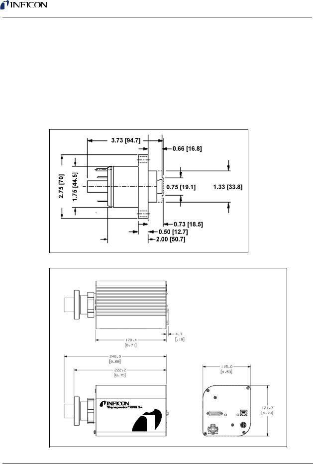
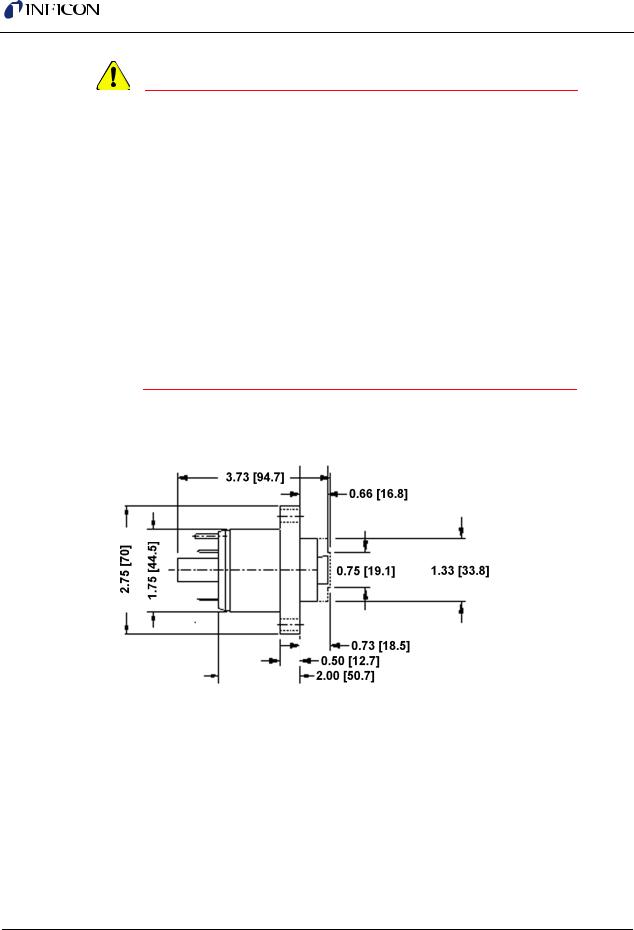
Figure 1-2 shows the overall physical dimensions ofTranspector XPR 3+ in inches [millimeters].
Figure 1-1 Sensor dimensions
Figure 1-2 Physical dimensions of Transpector XPR 3+
1 - 5

Transpector XPR 3+ Operating Manual
1.9.2 Weight
Transpector XPR 3+ electronics module weighs 1.62 kg (3.58 lbs).
1.9.3 Mounting Requirements
The sensor is mounted to a high-vacuum chamber with a standard 2.75 in. (69.9 mm) O.D. ConFlat flange.
The electronics module attaches to and is supported by the sensor. Transpector XPR 3+ can be mounted in any position. See section 1.16.5, Sensor
Installation, on page 1-19 for information on installing Transpector XPR 3+ system.
1.9.4 Ventilation Requirements
At least 25.4 mm (1 in.) of open space around the Transpector XPR 3+ electronics module must be maintained for proper ventilation.
1.9.5 Maintenance Access
Easy access to Transpector XPR 3+ should be maintained for installation and maintenance activities.
1.10 Electrical Power Requirements
Transpector XPR 3+ must be connected to a source of power as specified in the following sections.
1.10.1 Required Supply Voltage
20 to 30 V(dc), 24 V(dc) typical
1.10.2Current Rating
1.25A maximum
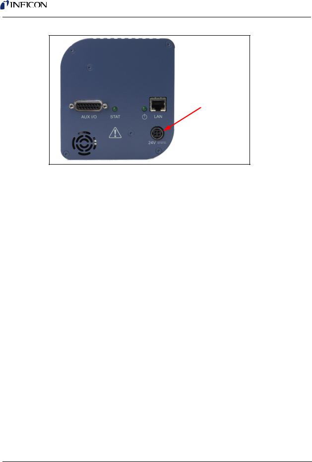
1.10.3Electrical Connection
Latching, 4-pin DIN connector, internally isolated from system ground.
See Figure 1-3.
1 - 6
Transpector XPR 3+ Operating Manual
Figure 1-3 Transpector XPR 3+ connections
Electrical Connection
1.11 Overvoltage Category
Overvoltage Category II (per EN61010-1)
1.12 Required Vacuum
Transpector XPR 3+: < 2.0x10⁻² Torr (2.66x10⁻² mbar) [2.66 Pascals]
1.13 Environmental Requirements
The following paragraphs explain the use, altitude range, humidity, pollution degree, and operating temperature for Transpector XPR 3+.
1.13.1 Use
Transpector XPR 3+ is designed for indoor use only.
1.13.2 Altitude Range
Transpector XPR 3+ can be used up to a maximum altitude range of 2000 m (6561 ft.).
1.13.3 Pollution Degree
Pollution Degree 2 (per EN61010-1)
1 - 7

Transpector XPR 3+ Operating Manual
1.13.4 Operating Temperature
Transpector XPR 3+ is designed to operate within a temperature range of 5°C to 50°C (41°F to 122°F).
1.13.5 Humidity
Transpector XPR 3+ is designed to operate in an environment with up to 98% relative humidity.
1.14 Computer System Requirements
Refer to the FabGuard Explorer Operating Manual (PN 074-528-P1) for computer system requirements.
1.15 Software Installation
Refer to the FabGuard Explorer Operating Manual (PN 074-528-P1) for information on installing the software and setting up the protocols necessary to ensure proper software operation.
1.16 Hardware Installation
The following steps must be performed to install Transpector XPR 3+
Gas Analysis System.
1If the optional Isolation Valve option was purchased with the
Transpector XPR 3+ install the Isolation Valve, see section 1.16.2 on page 1-11.
2If the optional Pirani Gauge Interlock was purchased with the Transpector XPR 3+ mount the Pirani Interlock Weldment Assembly, see section 1.16.3 on page 1-17.
3If the optional Pirani Gauge Interlock was purchased with the Transpector XPR 3+ mount the Pirani Gauge, see section 1.16.4 on page 1-18.
4Install the Transpector XPR 3+ Sensor, see section 1.16.5 on page 1-19.
5Install the Transpector Electronics Module, see section 1.16.6 on page 1-22.
6Install the Communications cables, see section 1.16.8 on page 1-23.
7Install the 24 V DC Power Supply, see section 1.16.9 on page 1-24.
8If the optional Pirani Gauge Interlock was purchased with the Transpector XPR 3+ install the Transpector XPR 3+ Interlock Cable, see section 1.16.10 on page 1-24.
1 - 8

Transpector XPR 3+ Operating Manual
9If the optional Pirani Gauge Interlock and/or the optional Isolation Valve were purchased with the Transpector XPR 3+ attach the Heating Jackets, see section 1.16.11 on page 1-25
10Install the Software.
1.16.1Avoiding Process Metal Deposition
CAUTION
Conductive deposits on the ceramic ion source plate from the process can cause electrical short circuits and a general failure of Transpector XPR 3+. The use of a 90o valve between the process and the sensor will alleviate this condition. The installation of a 90o valve is described in ConFlat Flanges.
The sensor is installed on a vacuum system with a 2.75 in. DN40 ConFlat flange. ConFlat flanges, and similar compatible types made by other manufacturers, are used for attaching devices to ports on high vacuum systems. If there are no concerns with the installation of this type of flange, proceed to section 1.16.5.1, Attaching the Sensor to the Vacuum Chamber, on page 1-19.
NOTE: If the system does not have a port with a compatible mating flange, an adapter will be necessary.
To install these flanges without leaks, follow proper operating procedures. These flanges are sealed with a metal gasket and can be heated for bakeout to temperatures of up to 200°C. For bakeout temperatures when a sensor is installed, see Table 1-1 on page 1-21.
1.16.1.1 Assembling ConFlat Flanges
To assemble a pair of ConFlat flanges:
1Wipe the sealing areas of the flanges with a laboratory towel using a clean solvent, such as water free alcohol. These areas must be clean and free of particulate matter.
CAUTION
Do not touch any surface on the gasket and flange faces with bare fingers. If it is necessary to touch any of these parts, always wear clean linen, nylon, powder free latex or vinyl laboratory gloves.
1 - 9
Transpector XPR 3+ Operating Manual
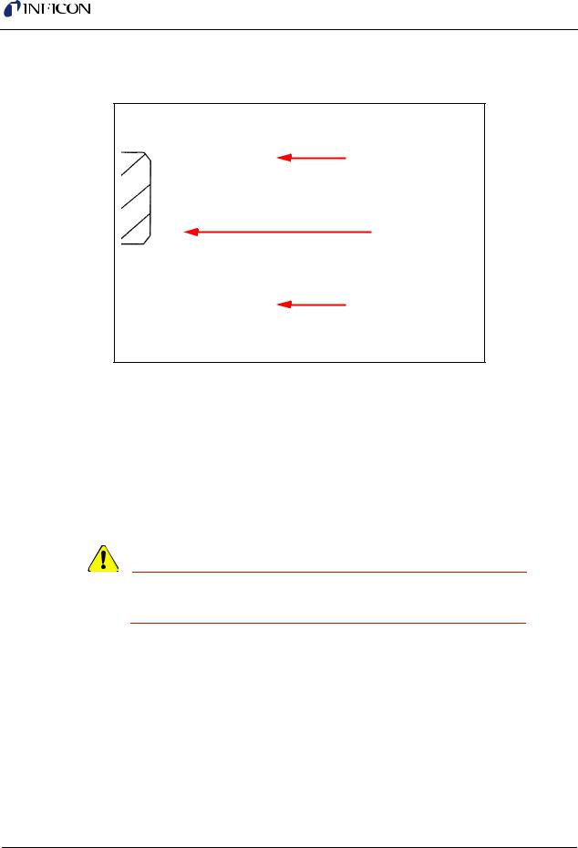
2Install the copper gasket between the two flanges. (See Figure 1-4.) Always use a new gasket. Do not attempt to use gaskets more than once.
Figure 1-4 Gasket and flange assembly
Flange
Copper Gasket
Flange
3Bring the two flanges together making sure that the gasket fits in the recess in both flanges. Flange faces should be parallel. If the gasket is properly seated, it should not be possible to slide the two flanges laterally with respect to each other.
4Install supplied silver-coated stainless steel bolts in the bolt holes of the flanges and finger-tighten.
NOTE: If the factory-supplied silver-coated stainless steel hardware is not
used and the flanges are going to be baked, coat the bolt threads with an anti-seize compound (FelPro® C 100 or equivalent).
CAUTION
Do not get any of the anti-seize compound on the gaskets or vacuum parts of the flange.
5After the bolts have been finger-tightened and the flange faces are parallel, tighten the bolts gradually and evenly in a star pattern until the flange faces are brought into even contact with each other.
1 - 10
Transpector XPR 3+ Operating Manual
1.16.2 Installing the Isolation Valve
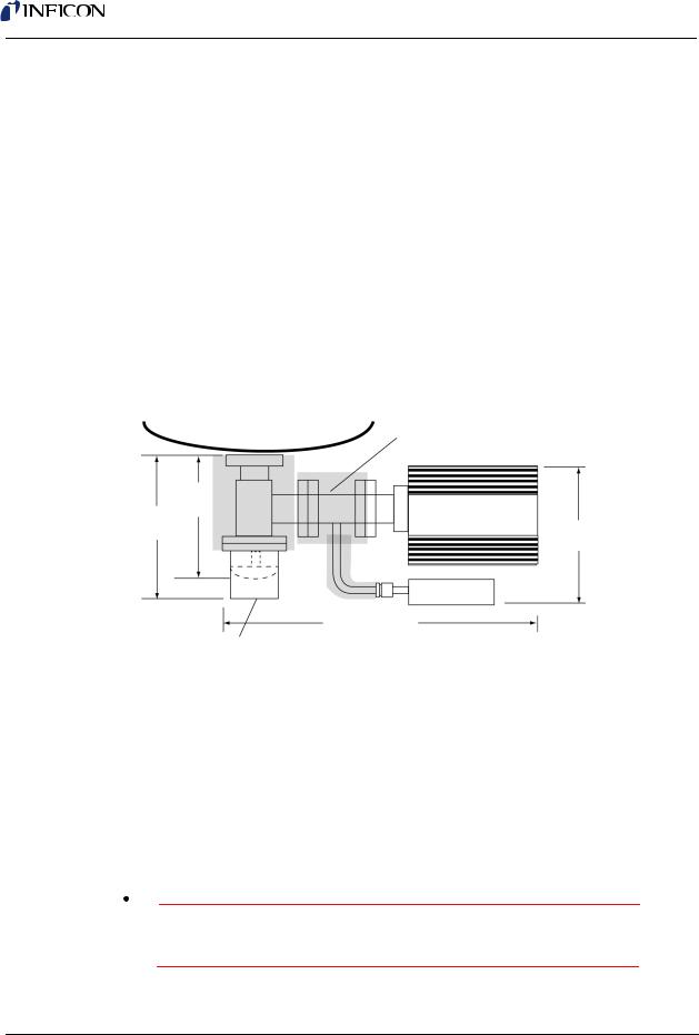
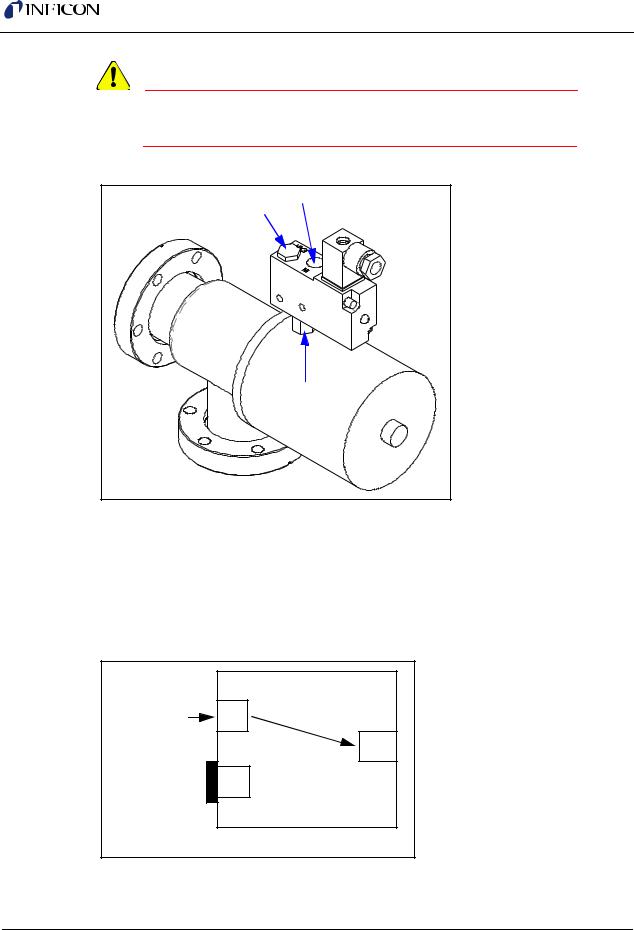
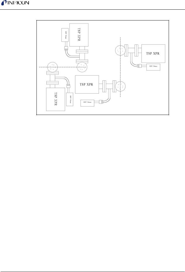
Transpector XPR 3+ should be installed on a 90° high-conductance isolation valve (1.5 in. [38 mm] outer diameter) mounted on the process chamber. This prevents line-of-sight deposits, from the plasma, from reaching the Transpector XPR 3+ Sensor. (See Figure 1-5.) The isolation valve may be provided by the user, or purchased from INFICON (see below). The isolation valve must be bakeable and needs to be fitted with a heating jacket designed for baking the valve.
1½" Right Angle Valve Hand Operated with Heating Jacket: IPN 914-024-G1
1½" Right Angle Valve Air Operated with 24 V(dc) Solenoid and Heating Jacket: IPN 961-025-G1
Valve Heating Jacket (150 °C; 120/230 V(ac) Operation): IPN 914-407-P1
Figure 1-5 |
Typical Connection of a Transpector XPR 3+ to the process chamber |
||||
|
|
|
|
||
|
Tool |
|
Interlock Weldment |
||
|
|
IPN 914-416-G1 |
|||
|
7.2 in. |
|
|
|
|
|
(18 cm) |
|
|
|
|
8.3 in. |
Manual |
|
Transpector XPR 3+ |
||
(21 cm) |
|
|
|
8.0 in. |
|
Air Operated |
|
|
|||
|
|
(20.4 cm) |
|||
|
|
|
|
||
|
|
|
Pirani Gauge |
||
|
|
|
IPN 918-401-P1 |
||
|
|
16.71 in. (42.5 cm) |
|||
|
The 90° Isolation Valve is |
|
|
|
|
|
located between the Tool |
|
|
|
|
|
|
|
Heating Jackets |
|
|
|
Chamber and Transpector XPR 3+. |
|
|
||
|
|
|
|
|
|
1.16.2.1 Notes for Air Operated Valve
The INFICON supplied air operated valve is a 1/8 in. ported, 3-way, single solenoid, 2-position spring return, Normally Open (NO) or Normally Closed (NC), general purpose air valve. It is configured for 2-way, NC use, whereby the EXH port is plugged and the air supply (60 - 100 psig) must be connected to the port labeled IN. (See Figure 1-6.)
 WARNING
The air pressure supplied to the valve must not exceed 100 psig.
1 - 11
Transpector XPR 3+ Operating Manual
CAUTION
The air pressure supplied to the valve must be at least 60 psig.
Figure 1-6 INFICON supplied air valve
EXH |
IN |
|
OUT |
1.16.2.2 Port Identification for 2-Way, Normally Closed Use
See Figure 1-7.
IN . . . . . . . . . . . . . . . . . . . . . . . . . . . Pressure supply port OUT . . . . . . . . . . . . . . . . . . . . . . . . . Delivery port to valve EXH . . . . . . . . . . . . . . . . . . . . . . . . . Exhaust port, plugged
Figure 1-7 Port identification
INLET |
IN |
AIR |
|
|
OUT |
PLUGGED |
EXH |
2 WAY NORMALLY CLOSED
1 - 12
Transpector XPR 3+ Operating Manual
1.16.2.3 Valve Parts List
 WARNING
This valve has an operational voltage rating of 24 V(dc) +10% to -15%.
Figure 1-8 Valve parts list
|
|
|
|
|
Item |
Description |
|
|
|
|
|
|
1 |
Solenoid Coil |
|
|
2 |
Connector Gasket |
|
|
3 |
Connector |
|
|
4 |
Connector Elbow |
|
|
5 |
Nut |
|
|
6 |
Washer |
|
|
7 |
Compression Ring |
|
|
8 |
Screw |
|
|
|
|
|
|
|
|
|
1 - 13

Transpector XPR 3+ Operating Manual
1.16.2.4 Wiring Instructions
1 Remove the screw (8).
Figure 1-9 Removing connector assembly
2 Remove the clear plastic connector elbow (4).
Figure 1-10 Removing connector elbow
3Remove the connector (3) from the solenoid assembly, be careful to not remove the connector gasket (2).
1 - 14
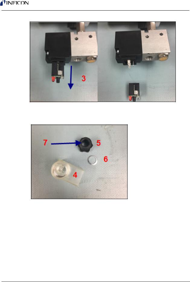
Transpector XPR 3+ Operating Manual
Figure 1-11 Removing connector terminal
4Remove the black plastic nut (5) from the connector elbow (4), the washer (6) and the compression ring (7) can stay in place.
Figure 1-12 Connect elbow assembly
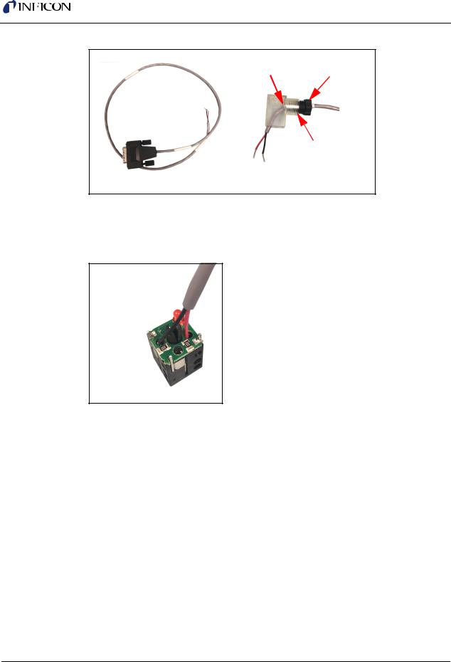
5Take the MMSP Valve/Relay Interface Cable (IPN 600-1450-P2) and run the cables through the nut (5), washer (6), compression ring (7) and the connector elbow (4).
1 - 15
Transpector XPR 3+ Operating Manual
Figure 1-13 Cable and connector elbow feed
6 5
4
7
6Connect the red and black wires to terminals 1 and 2 in either order. This can be done by soldering the wires in place or using the appropriate screw terminals on the connector (3) assembly.
Figure 1-14 Connecting the red and black wires to the terminal
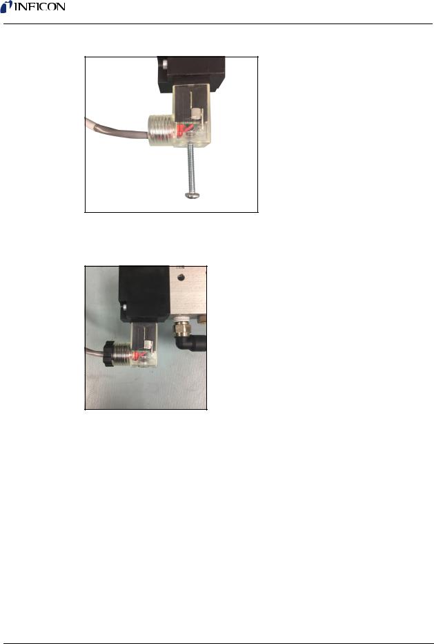
7Press the connector (3) back into the connector elbow (4) screw the nut (5) securely into place. Connect the connector (3) to the solenoid coil (1) noting the connection scheme NOTE: When fitting the connector (3) into the connector elbow (4) note the orientation of the connection to the solenoid coil (1). Ideally the elbow should be facing away from the inlet air connection point as it can interfere with the connection of the inlet air.
1 - 16
Transpector XPR 3+ Operating Manual
Figure 1-15 Connecting the connector
8Screw the assembly back into the solenoid coil using the screw (8) removed in step 1.
Figure 1-16 Screw the assembly back into the solenoid coil
1.16.3 Mounting the Pirani Interlock Weldment Assembly
Transpector XPR 3+ Interlock Weldment Assembly with a Pirani gauge port has a 1.5 in. (38 mm) inner diameter for the Transpector XPR 3+ sensor. Both CF-40 flanges rotate to provide flexibility in orientation of the Pirani gauge with respect to the Transpector electronics module, the isolation valve, and the tool.
1Evaluate, or pre-fit, Transpector XPR 3+ on the tool port to determine the orientation of the Transpector electronics module with respect to the tool, and the Pirani gauge with respect to a side of the Transpector electronics module. Typically, the Pirani gauge is placed under the Transpector electronics module if the axis of Transpector XPR 3+ is horizontal, as shown in Figure 1-17.
NOTE: For measurements of 2x10⁻² Torr or less, that are involved in protection of the Transpector XPR 3+ filament, the Pirani gauge retains its accuracy in any orientation.
1 - 17
Transpector XPR 3+ Operating Manual
Figure 1-17 Orientations for mounting an Transpector XPR 3+ on a tool
2Attach the Interlock Weldment Assembly to the 1½ in. Right Angle Valve with a Cu gasket using ¼-28 x 1¼ in. 12 pt SS silver plated bolts, with the nut plates on the Valve side. Tighten the bolts finger tight.
3Check for orientation and alignment: the Pirani gauge tube should be oriented so that the VCR fitting is facing away from the valve.
4Tighten all the bolts evenly and gradually in a star pattern until the flange faces come into contact.
1.16.4Mounting the Pirani Gauge
The Pirani gauge is UHV compatible with a SS body, ceramic electrical feed-through and a 8-VCR female mounting flange.
1Connect the Pirani gauge flange to the port on the Interlock Weldment Assembly using a Ni-8-VCR -2 silver plated Ni gasket.
2Adjust the orientation of the Pirani gauge and tighten the gland finger tight. Use a 1-1/16 in. open end wrench for the female nut and a 15/16 in. open end for the male nut.
NOTE: For Ni gaskets, tighten an additional 1/8 turn (45 degrees) beyond finger tight with the wrenches to seal the Pirani gauge fitting. Rotation of the Pirani gauge can be inhibited by rotating the male nut and keeping the female nut wrench fixed.
1 - 18

Transpector XPR 3+ Operating Manual
1.16.5 Sensor Installation
CAUTION
Do not touch any surface on the vacuum side of the sensor with bare fingers. If it is necessary to touch any of these parts, always wear clean linen, nylon, powder free latex or vinyl laboratory gloves.
Before installing the sensor on your system, check for any signs of loose or broken parts.
Do not attempt to clean the sensor in any kind of solvent. Cleaning the sensor requires its disassembly. If the sensor is contaminated and needs cleaning, contact INFICON.
1.16.5.1 Attaching the Sensor to the Vacuum Chamber
The sensor may be mounted in any position when attaching it to the vacuum vessel or chamber.
1Attach the Transpector XPR 3+ Sensor Flange to the Pirani Interlock Weldment Assembly CF-40 Flange with a Cu gasket using ¼-28 x 1¼ in. 12pt SS silver plated bolts, with the nut plates on the Transpector XPR 3+ side of the Flange. Tighten the bolts finger tight.
2Tighten all the bolts evenly and gradually in a star pattern until the flange faces come into contact.
1 - 19
Transpector XPR 3+ Operating Manual
CAUTION
Avoid mounting the sensor near any magnetic fields greater than two gauss.
It is important that the connection between the sensor and the vacuum chamber does not interfere with gas exchange to ensure that the gas composition accurately reflects that existing in the vacuum chamber.
If materials are evaporated or coatings are deposited in the vacuum chamber, the sensor must be protected against the deposition of these materials on its surfaces by installing a baffle or deflector.
In systems which are baked, include the sensor in the bakeout zone or provide it with separate heaters.
Dimensions of the quadrupole sensors are shown in Figure 1-18.
Figure 1-18 Sensor dimensions
1 - 20

Transpector XPR 3+ Operating Manual
CAUTION
The silver-plated bolts used for mounting the sensor to the vacuum system must be oriented such that the bolt heads are on the same side of the sensor as the electronics box. Otherwise, there may be interference between the black INFICON Transpector mounting nut and sensor mounting hardware.
CAUTION
Maximum bakeout temperature for sensors is shown in
Table 1-1.
Table 1-1 Sensor maximum bakeout temperature
|
Maximum |
Maximum Bakeout |
|
Operating |
Temperature |
Sensor |
Temperature |
Electronics Removed |
|
|
|
Transpector XPR 3+ |
150°C |
200°C |
|
|
|
CAUTION
Transpector XPR 3+ electronics module must be removed prior to bakeout at temperatures greater than 150°C (FC).
Do not turn on the Electron Multiplier (EM) at sensor temperatures above 150°C. Turning on the EM at elevated temperature could result in permanent damage to the detector.
 WARNING
During or immediately after bakeout, the heating jacket and metal surfaces in the vicinity of the heating jacket may be extremely hot. These surfaces may exceed 100°C at the maximum ambient operating temperature (50°C), which will cause burns if touched directly without using the proper personal protection equipment.
1 - 21
Transpector XPR 3+ Operating Manual
1.16.6 Electronics Module Installation
Transpector XPR 3+ electronics module must be mounted in an area where the ambient temperature does not exceed 50°C and there is free air circulation around the electronics module. Best performance will be achieved if the electronics module is not located close to major heat sources where it is subjected to wide temperature variations. (See Figure 1-19.)
After the sensor has been installed on the vacuum system, the Transpector XPR 3+ electronics module must be mounted on the sensor:
1The Transpector XPR 3+ sensor mounting connector assembly includes a mounting nut, a flat teflon ring, and an O-ring. When the mounting nut is tightened, the O-ring compresses making a tight fit on the sensor housing. For proper installation, place the nut over the end of the sensor and roll the O-ring back to the groove on the sensor.
2Note the alignment pin or key pin and match the sensor feedthrough to the electronics module and carefully slide the Transpector XPR 3+ module onto the sensor. Ensure the Transpector XPR 3+ electronics module slides on fully.
3Hand tighten the mounting nut on the Transpector XPR 3+ sensor.
4Continue to section 1.16.8 and install the communications cable.
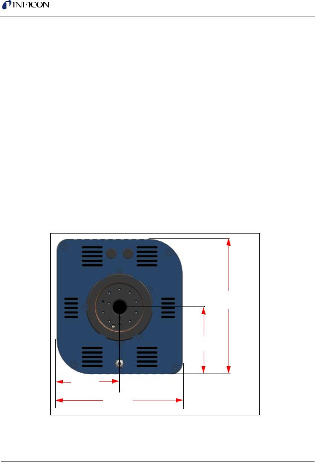
Figure 1-19 Electronics module dimensions
121.67 mm |
(4.79 in.) |
60.32 mm |
(2.375 in.) |
57.48 mm |
(2.263 in.) |
114.96 mm |
4.526 in. |
1 - 22
Loading...