


Operating Manual
Incl. EC Declaration of Conformity
Single-Channel Controller
VGC401
para |
tinb01e1-f (2011-07) |
1 |
Product Identification In all communications with INFICON, please specify the information on the product nameplate. For convenient reference copy that information into the space provided below:
Model:
PN:
SN:
V Hz W 
Validity |
This document applies to products with part number |
|
398-010. |
|
The part number (PN) can be taken from the product |
|
nameplate. |
|
This document is based on firmware number 302-519-E. |
|
If your unit does not work as described in this document, |
|
please check that it is equipped with the above firmware |
|
version (→ 49). |
|
We reserve the right to make technical changes without |
|
prior notice. |
|
All dimensions are indicated in mm. |
2 |
tinb01e1-f (2011-07) VGC401.om |

Intended Use |
The VGC401 is used together with INFICON Transmit- |
|
|
ters (in this document referred to as gauges) for total |
|
|
pressure measurement. All products must be operated in |
|
|
accordance with their respective Operating Manuals. |
|
Scope of Delivery |
1× |
Single-Channel Controller |
|
1× Power cord |
|
|
1× Rubber bar |
|
|
2× Rubber feet |
|
|
4× |
Collar screws |
|
4× |
Plastic sleeves |
|
1× CD-ROM (Operating Manuals) |
|
|
1× |
EC Declaration of Conformity |
|
1× |
Installation Manual |
tinb01e1-f (2011-07) VGC401.om |
3 |

Contents
Product Identification |
2 |
||
Validity |
2 |
||
Intended Use |
3 |
||
Scope of Delivery |
3 |
||
1 |
Safety |
6 |
|
1.1 |
Symbols Used |
6 |
|
1.2 |
Personnel Qualifications |
6 |
|
1.3 |
General Safety Instructions |
7 |
|
1.4 |
Liability and Warranty |
8 |
|
2 |
Technical Data |
9 |
|
3 |
Installation |
13 |
|
3.1 |
Personnel |
13 |
|
3.2 |
Installation, Setup |
13 |
|
3.2.1 |
Rack Installation |
13 |
|
3.2.2 Installation in a Control Panel |
18 |
||
3.2.3 Use as Desk-Top Unit |
19 |
||
3.3 |
Mains Power Connector |
20 |
|
3.4 |
SENSOR Connector |
22 |
|
3.5 |
CONTROL Connector |
23 |
|
3.6 |
RS232 Interface Connector |
25 |
|
4 |
Operation |
26 |
|
4.1 |
Front Panel |
26 |
|
4.2 |
Turning the VGC401 On and Off |
27 |
|
4.3 |
Operating Modes |
27 |
|
4.4 |
Measurement Mode |
28 |
|
4.5 |
Parameter Mode |
31 |
|
4.5.1 |
Parameters |
34 |
|
4.6 |
Test Mode |
47 |
|
4.6.1 |
Parameters |
49 |
|
4.6.2 |
Test Programs |
50 |
|
5 |
Communication (Serial Interface) |
55 |
|
5.1 |
RS232C Interface |
55 |
|
5.1.1 |
Data Transmission |
55 |
|
5.1.2 |
Communication Protocol |
57 |
|
5.2 |
Mnemonics Mnemonics |
59 |
|
5.2.1 |
Measurement Mode |
60 |
|
5.2.2 |
Parameter Mode |
64 |
|
5.2.3 |
Test Mode |
71 |
|
5.2.4 |
Example |
75 |
|
4 |
tinb01e1-f (2011-07) VGC401.om |

6 |
Maintenance |
76 |
7 |
Troubleshooting |
77 |
8 |
Repair |
79 |
9 |
Accessories |
79 |
10 |
Storage |
80 |
11 |
Disposal |
80 |
Appendix |
81 |
|
A: |
Conversion Tables |
81 |
B: |
Default Parameters |
82 |
C: |
Firmware Update |
83 |
D: |
Literature |
86 |
E: |
Index |
89 |
ETL Certification |
91 |
|
EC Declaration of Conformity |
92 |
|
For cross-references within this document, the symbol (→ XY) is used, for cross-references to further documents listed under "Literature", the symbol (→ [Z]).
tinb01e1-f (2011-07) VGC401.om |
5 |
1 Safety
1.1Symbols Used
Symbols for residual risks
Further symbols
1.2Personnel Qualifications
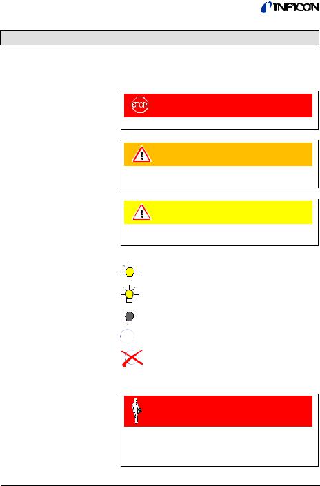
DANGER
Information on preventing any kind of physical injury.
WARNING
Information on preventing extensive equipment and environmental damage.
Caution
Information on correct handling or use. Disregard can lead to malfunctions or minor equipment damage.
The lamp/display is lit.
The lamp/display flashes.
The lamp/display is dark.
para
Press the key (example: 'para' key).
Do not press any key
Skilled personnel
All work described in this document may only be carried out by persons who have suitable technical training and the necessary experience or who have been instructed by the end-user of the product.
6 |
tinb01e1-f (2011-07) VGC401.om |

1.3General Safety Instructions
Disconnecting device
Adhere to the applicable regulations and take the necessary precautions for all work you are going to do and consider the safety instructions in this document.
DANGER
DANGER: mains voltage
Contact with live parts is extremely hazardous when any objects are introduced or any liquids penetrate into the unit.
Make sure no objects enter through the louvers and no liquids penetrate into the equipment.
The disconnecting device must be readily identifiable and easily reached by the user.
To disconnect the controller from mains, you must unplug the mains cable.
Disconnecting device acc. to EN 61010-1
Communicate the safety instructions to all other users.
tinb01e1-f (2011-07) VGC401.om |
7 |

1.4Liability and Warranty
INFICON assumes no liability and the warranty becomes null and void if the end-user or third parties
•disregard the information in this document
•use the product in a non-conforming manner
•make any kind of interventions (modifications, alterations etc.) on the product
•use the product with accessories not listed in the corresponding documentation.
8 |
tinb01e1-f (2011-07) VGC401.om |

2 Technical Data
Mains specifications
Ambiance
Compatible gauges
Voltage |
90 … 250 VAC |
|
Frequency |
50 … 60 Hz |
|
Power consumption |
≤30 VA |
|
Overvoltage category |
II |
|
Protection class |
1 |
|
Connection |
European appliance connec- |
|
|
tor IEC 320 C14 |
|
Temperature |
|
|
storage |
–20 … +60 °C |
|
operation |
+ 5 … +50 °C |
|
Relative humidity |
≤80% up to +31 °C, |
|
|
decreasing to 50% at +40 °C |
|
Use |
indoors only |
|
|
max. altitude 2000 m NN |
|
Pollution degree |
II |
|
Protection type |
IP30 |
|
Number |
1 |
|
Compatible types |
|
|
Pirani |
PSG |
(PSG400, PSG400-S, |
|
|
PSG100-S, PSG101-S, |
|
|
PSG500, PSG500-S, |
|
|
PSG502-S, PSG510-S, |
|
|
PSG512-S, PSG550, |
|
|
PSG552, PSG554) |
Pirani/Capacitive |
PCG |
(PCG400, PCG400-S, |
|
|
PCG550, PCG552, |
|
|
PCG554) |
Cold cathode |
PEG |
(PEG100) |
Cold cathode/Pirani |
MPG |
(MPG400, MPG401) |
Hot cathode |
BAG |
(BAG100-S, BAG101-S) |
Hot cathode/Pirani |
BPG |
(BPG400, BPG402) |
|
HPG |
(HPG400) |
Capacitive |
CDG |
(CDG025, CDG025D, |
|
|
CDG045, CDG045-H, |
|
|
CDG045D, CDG100, |
|
|
CDG100D, CDG160D) |
TripleGauge™ |
|
|
Hot cathode/Pirani/ |
|
|
Capacitive |
BCG |
(BCG450) |
tinb01e1-f (2011-07) VGC401.om |
9 |

Gauge connection
Operation
Measurement values
Number |
2 (parallel) |
|
|
|
|
|
|
Caution |
|
|
|
|
Do not connect more than one |
|
|
gauge at the same time. |
|
SENSOR connector |
15-pin D-Sub, female |
|
|
RJ45 (FCC68), female |
|
|
(pin assignment → 23) |
|
Front panel |
via 3 keys |
|
HOST (remote control) |
via RS232C interface |
|
Measurement ranges |
depending on gauge |
|
|
(→ |
[1] … [21]) |
Measurement error |
|
|
gain error |
≤0.02% FSr |
|
offset error |
≤0.05% FSr |
|
Measurement rate |
|
|
analog |
100 / s |
|
digital |
50 / s (BPG, HPG, BCG, |
|
|
10 / s |
CDGxxxD1)) |
|
(BAG) |
|
Display rate |
10 / s |
|
Filter time constant |
|
|
slow |
750 ms (fg = 0.2 Hz) |
|
normal (nor) |
150 ms (fg = 1 Hz) |
|
fast |
20 ms (fg = 8 Hz) |
|
Pressure units |
mbar, Pa, Torr, Micron |
|
Zero adjust |
for linear gauges |
|
Correction factor |
for logarithmic gauges |
|
|
0.10 … 10.00 |
|
A/D converters |
resolution >0.001% FSr |
|
|
(The measurement values of |
|
|
BPG, HPG, BCG, BAG and |
|
|
CDGxxxD are transmitted |
|
|
digitally.) |
|
1)CDG025D, CDG045D, CDG100D, CDG160D
10 |
tinb01e1-f (2011-07) VGC401.om |
Gauge supply
Switching function
Switching function relay
Error signal
Error signal relay
Voltage |
+24 VDC ±5% |
Current |
750 mA |
Power consumption |
18 W |
Fuse protection |
900 mA with PTC element, |
|
self-resetting after turning the |
|
VGC401 off or disconnecting |
|
the gauge |
Number |
1 |
Reaction delay |
≤10 ms if switching threshold |
|
close to measurement value |
|
(for larger differences con- |
|
sider filter time constant). |
Adjustment range |
depending on gauge |
|
(→ [1] … [21]) |
Hysteresis |
≥1% FSr for linear gauges |
|
≥10% of measurement value |
|
for logarithmic gauges |
Contact type |
floating changeover contact |
Load max. |
60 VDC, 1 A (ohmic) |
|
30 VAC, 2 A (ohmic) |
Service life |
108 cycles |
mechanic |
|
electric |
105 cycles (at maximum load) |
Contact positions |
→ 24 |
CONTROL connector |
9-pin D-Sub, male |
|
(pin assignment → 24) |
Number |
1 |
Reaction time |
≤20 ms |
Contact type |
floating normally open contact |
Load max. |
60 VDC, 1 A (ohmic) |
|
30 VAC, 2 A (ohmic) |
Service life |
108 cycles |
mechanic |
|
electric |
105 cycles (at maximum load) |
Contact positions |
→ 24 |
CONTROL connector |
9-pin D-Sub, male |
|
(pin assignment → 24) |
tinb01e1-f (2011-07) VGC401.om |
11 |
Analog output |
Number |
1 |
|
|
|
|
||||||||
|
|
|
|
|
|
|
Voltage range |
0 … +10 V |
||||||
|
|
|
|
|
|
|
Internal resistance |
660 Ω |
|
|
|
|||
|
|
|
|
|
|
|
Measurement signal |
depending on gauge |
||||||
|
|
|
|
|
|
|
vs. pressure |
(→ |
[1] … [21]) |
|||||
|
|
|
|
|
|
|
CONTROL connector |
9-pin D-Sub, male |
||||||
|
|
|
|
|
|
|
|
|
(pin assignment → 24) |
|||||
Interface |
Standard |
RS232C |
||||||||||||
|
|
|
|
|
|
|
Protocol |
ACK/NAK, ASCII with |
||||||
|
|
|
|
|
|
|
|
|
3-character mnemonics, |
|||||
|
|
|
|
|
|
|
|
|
bi-directional data flow, |
|||||
|
|
|
|
|
|
|
|
|
8 data bits, no parity bit, |
|||||
|
|
|
|
|
|
|
|
|
1 stop bit |
|||||
|
|
|
|
|
|
|
RS232C |
only TXD and RXD used |
||||||
|
|
|
|
|
|
|
Transmission rate |
9600, 19200, 38400 baud |
||||||
|
|
|
|
|
|
|
RS232 connector |
9-pin D-Sub, female |
||||||
|
|
|
|
|
|
|
|
|
(pin assignment → 25) |
|||||
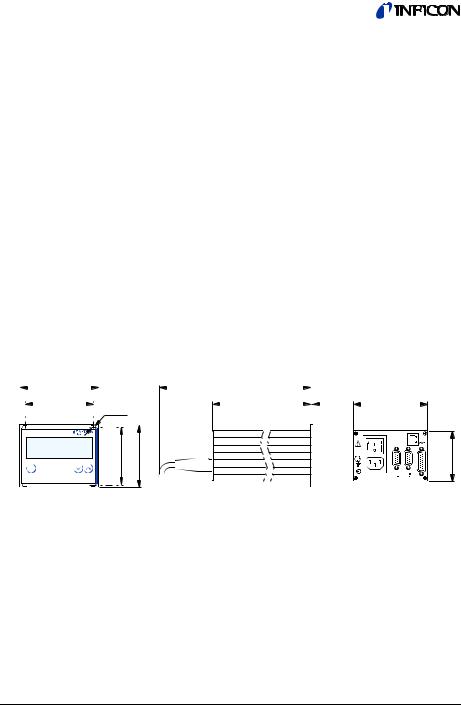
Dimensions [mm] |
|
|
|
|
|
|
|
|
||||||
106.2 |
|
|
|
|
|
285 |
|
|
|
|
|
|
||
|
|
|
|
|
|
|
|
|
|
|
|
|
||
91.2 |
|
|
|
ø3.5 |
|
204.5 |
|
|
2.5 |
103.6 |
|
|||
|
|
|
|
|
|
|
|
|
|
|
|
|
|
|
|
|
|
|
|
|
|
|
|
|
|
||||
|
|
|
|
|
|
|
|
|
|
|
|
|
|
|
78 |
84 |
67.3 |
para |
|
|
Use |
For incorporation into a rack or control panel or as desk- |
|
top unit |
Weight |
0.85 kg |
12 |
tinb01e1-f (2011-07) VGC401.om |
3 Installation
3.1 Personnel
Skilled personnel
The unit may only be installed by persons who have suitable technical training and the necessary experience.
3.2 Installation, Setup
3.2.1 Rack Installation
The VGC401 is suited for incorporation into a 19" rack or a control panel or for use as desk-top unit.
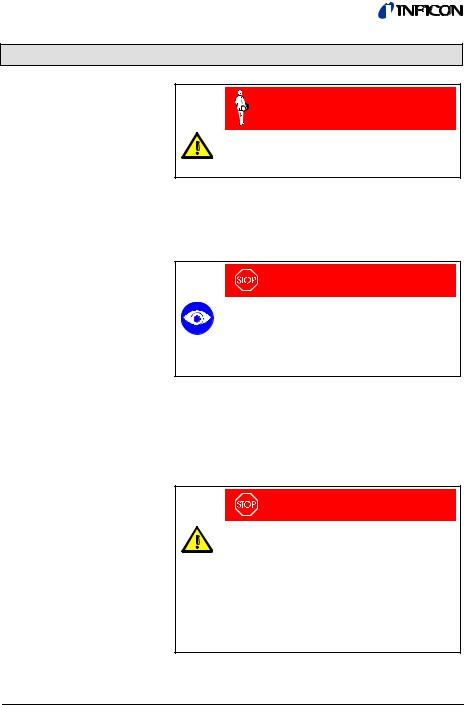
DANGER
DANGER: damaged product
Putting a damaged product into operation can be extremely hazardous.
In case of visible damages, make sure the product is not put into operation.
The VGC401 is designed for installation into a 19" rack chassis adapter according to DIN 41 494. For this purpose, four collar screws and plastic sleeves are supplied with it.
DANGER
DANGER: protection class of the rack
If the product is installed in a rack, it is likely to lower the protection class of the rack (protection against foreign bodies and water) e.g. the EN 60204-1 regulations for switching cabinets.
Take appropriate measures for the rack to meet the specifications of the protection class.
tinb01e1-f (2011-07) VGC401.om |
13 |
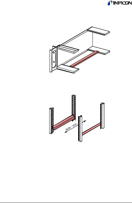
Guide rail
Slide rails
In order to reduce the mechanical strain on the front panel of the VGC401, preferably equip the rack chassis adapter with a guide rail.
For safe and easy installation of heavy rack chassis adapters, preferably equip the rack frame with slide rails.
14 |
tinb01e1-f (2011-07) VGC401.om |

Mounting height |
Rack installation |
Height 2 U |
Height 3 U |
Height 2 U rack chassis adapter
n Secure the rack chassis adapter in the rack frame.
The admissible maximum ambient temperature (→ 9) must not be exceeded neither the air circulation obstructed.
Rack chassis adapter
Height 2 U
tinb01e1-f (2011-07) VGC401.om |
15 |
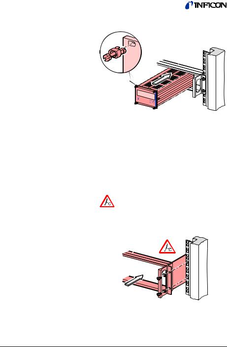
o Slide the VGC401 into the adapter …
Height 2 U
Height 3 U rack chassis adapter
… and fasten the VGC401 to the rack chassis adapter using the screws supplied with it.
For incorporation into a 19" rack chassis adapter, height 3, an adapter panel (incl. two collar screws and plastic sleeves) is available (→ 79).
n Secure the rack adapter in the rack frame.
The admissible maximum ambient temperature (→ 9) must not be exceeded neither the air circulation obstructed.
Rack chassis adapter
Height 3 U
16 |
tinb01e1-f (2011-07) VGC401.om |
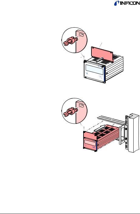
o
p
Mount the adapter panel as upper extension to the
front panel of the VGC401 using the screws supplied with the adapter panel.
Adapter panel (Height 2 U to height 3 U)
Slide the VGC401 into the rack chassis adapter …
Height 3 U
…and fasten the adapter panel to the rack chassis adapter using the screws supplied with the VGC401.
tinb01e1-f (2011-07) VGC401.om |
17 |

3.2.2Installation in a Control Panel
DANGER
DANGER: protection class of the control panel
If the product is installed in a rack, it is likely to lower the protection class of the rack (protection against foreign bodies and water) e.g. according to the EN 60204-1 regulations for switching cabinets.
Take appropriate measures for the control panel to meet the specifications of the protection class.
For mounting the VGC401 into a control panel, the following cut-out is required:
105 |
91.2 |
78 69
M3 or ø 3.5
The admissible maximum ambient temperature (→ 9) must not be exceeded neither the air circulation obstructed.
For reducing the mechanical strain on the front panel, preferably support the unit.
nSlide the VGC401 into the cut-out of the control panel …
… and secure it with four M3 or equivalent screws.
18 |
tinb01e1-f (2011-07) VGC401.om |

3.2.3Use as Desk-Top Unit
The VGC401 is also suited for use as desk-top unit. For this purpose, two self-adhesive rubber feet as well as a slip-on rubber bar are supplied with it.
nStick the two supplied rubber feet to the rear part of the bottom plate …
… and slip the supplied rubber bar onto the bottom edge of the front panel.
Select a location where the admissible maximum ambient temperature (→ 9) is not exceeded (e.g. due to sun irradiation).
tinb01e1-f (2011-07) VGC401.om |
19 |
3.3Mains Power Connector
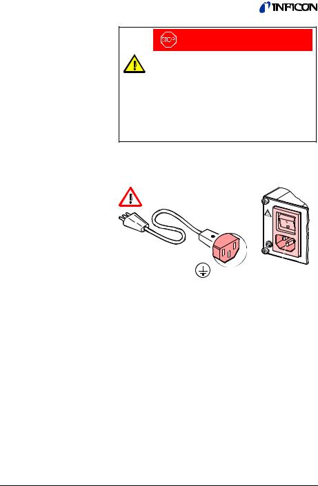
DANGER
DANGER: line voltage
Incorrectly grounded products can be extremely hazardous in the event of a fault.
Use only a 3-conductor power cable (3×1.5 mm2) with protective ground. The
power connector may only be plugged into a socket with a protective ground. The protecttion must not be nullified by an extension cable without protective ground.
The unit is supplied with a 2.5 m power cord. If the mains cable is not compatible with your system, use your own, suitable cable with protective ground.
The socket must be fuseprotected with 10 Amax
Disconnecting device acc. to EN 61010-1
If the unit is installed in a switch cabinet, the mains voltage should be supplied and turned on via a central power distributor.
20 |
tinb01e1-f (2011-07) VGC401.om |
Grounding |
On the rear of the unit, there is a screw which can be |
|
used to connect the unit to ground, e.g. using the |
|
grounding of the pumping station. |
|
Do not unfasten this |
Ground screw |
screw (internal |
|
ground protection) |
tinb01e1-f (2011-07) VGC401.om |
21 |
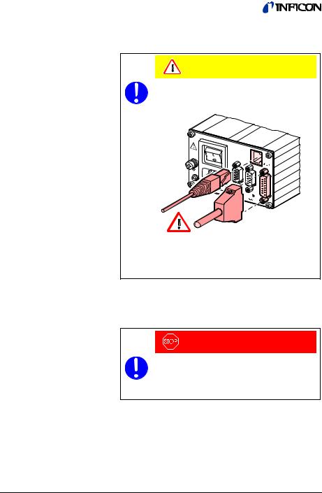
3.4SENSOR Connector
The VGC401 is equipped with two different gauge connectors.
Caution
Caution: one channel measurement unit
Connecting more than one gauge at the same time may lead to gauge destruction.
1 only at once
Make sure that there is never more than one gauge connected to the VGC401 at the same time.
Connect the gauge to one of the two SENSOR connectors on the rear of the unit. Use a screened 1:1 cable (electromagnetic compatibility). Make sure the gauge is compatible (→ 9).
DANGER
DANGER: protective low voltage
According to EN 61010, voltages exceeding 30 VAC or 60 VDC are hazardous.
Only connect a protective low voltage (SELV).
22 |
tinb01e1-f (2011-07) VGC401.om |
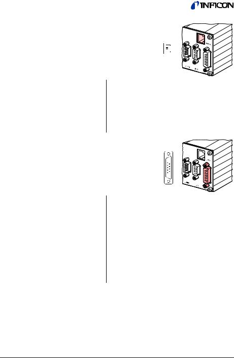
Pin assignment
SENSOR
Pin assignment of the 8-pin RJ45 appliance connector:
8
1
Pin |
Signal |
|
4 |
Identification |
|
1 |
Supply |
+24 VDC |
2 |
Supply common |
GND |
3 |
Signal input |
(Measurement signal+) |
5 |
Signal common |
(Measurement signal–) |
6Status
7HV_L
8HV_H
Pin assignment of the female 15-pin D-Sub appliance connector:
15
 8
8
9
 1
1
Pin |
Signal |
|
10 |
Identification |
|
8 |
Supply for BPG, HPG, BCG and BAG |
|
11 |
Supply for CDG |
|
5 |
Supply common |
GND |
2 |
Signal input |
(Measurement signal+) |
12 |
Signal common |
(Measurement signal–) |
3 |
Status |
|
1 |
Emission status |
|
7 |
Degas |
|
4 |
HV_H |
|
13RXD
14TXD
15Screening = chassis
6, 9 not connected
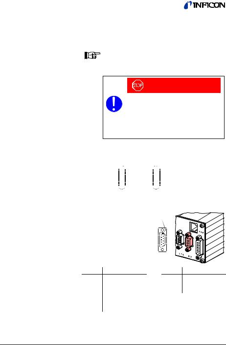
3.5CONTROL Connector
This connector allows to read the measurement signal, to evaluate state of the floating switching function and error contacts, and to activate/deactivate the high vacuum measurement circuit (only for PEG cold cathode gauge and BAG ionization vacuum gauge).
tinb01e1-f (2011-07) VGC401.om |
23 |

Connect the peripheral components to the CONTROL connector on the rear of the unit. Use a screened cable (electromagnetic compatibility).
|
|
|
|
DANGER |
|
|
|
DANGER: protective low voltage |
|||
|
|
According to EN 61010, voltages ex- |
|||
|
|
ceeding 30 VAC or 60 VDC are haz- |
|||
|
|
ardous. |
|
||
|
|
Only connect a protective low voltage |
|||
|
|
(SELV). |
|
||
Pin assignment |
|
|
|
|
|
Contact positions |
|
|
|
|
|
CONTROL |
Pin assignment of |
|
|
|
|
|
the male 9-pin D-Sub |
5 |
9 |
||
|
appliance connector: |
1 |
6 |
||
|
|
|
|
||
|
|
|
|
|
|
|
Pin |
Signal |
|
|
|
|
1 |
Analog output |
|
0 … +10 VDC |
|
|
7 |
Chassis = GND |
|
|
|
|
5 |
HV_H on |
+24 V |
|
|
|
|
off |
0 V |
|
|
|
|
The control over this signal is placed superior to the key |
|||
|
|
operation. |
|
|
|
|
4 |
Pressure below |
Pressure above |
||
|
3 |
threshold or power |
|||
|
threshold |
|
|||
|
2 |
|
supply turned off |
||
|
|
|
|
||
|
|
Error signal |
|
|
|
|
9 |
No error |
|
Error or power |
|
|
8 |
|
supply turned off |
||
|
|
|
|
||
|
|
Supply for relays with higher switching power |
|||
|
|
|
|
Fuse-protected at 300 mA with PTC |
|
|
6 |
+24 VDC, 200 mA |
element, self-resetting after power |
||
|
off or pulling the CONTROL con- |
||||
|
7 |
Chassis = GND |
nector. Meets the requirements of a |
||
|
|
|
|
grounded protective extra low |
|
|
|
|
|
voltage (SELV). |
|
The analog output (pin 1) differ from the displayed value by no more than ±50 mV.
24 |
tinb01e1-f (2011-07) VGC401.om |
3.6RS232 Interface Connector
Pin assignment
RS232
The RS232C interface allows for operating the VGC401 via a HOST or terminal. It can also be used for updating the firmware (→ 83).
Connect the serial interface to the RS232 connector on the rear of the unit using your own, screened (electromagnetic compatibility) cable.
DANGER
DANGER: protective low voltage
According to EN 61010, voltages exceeding 30 VAC or 60 VDC are hazardous.
Only connect a protective low voltage (SELV).
e.g. PC |
VGC401 |
Screening 


 Screening
RXD 


 2 TXD
2 TXD
TXD 
 3 RXD
3 RXD
GND 


 5 GND
5 GND
(Minimum configuration)
Screening
Pin assignment |
1 |
6 |
|
|
of the female |
5 |
9 |
|
|
9-pin D-Sub |
|
|
||
|
|
|
||
appliance con- |
|
|
|
|
nector: |
|
|
|
|
Pin |
Signal |
|
Pin |
Signal |
2 |
TXD |
|
1 |
not connected |
3 |
RXD |
|
4 |
not connected |
5 |
GND |
|
7 |
not connected |
6 |
DSR |
|
Chassis = screening |
|
8CTS
9GND
tinb01e1-f (2011-07) VGC401.om |
25 |

4 Operation
4.1 Front Panel
Measurement value in floating point or exponential format or status messages
Warning/error
(flashing)
Switching function status
Pressure
unit
para
 Upper threshold
Lower threshold
para
Operator keys
 Offset value ≠ 0
Correction factor ≠ 1
High vacuum measurement circuit activated
(PEG, MPG, BAG, BPG402 and BCG only) Degas activated ( BPG, BCG and BAG only)
Parameter mode activated
26 |
tinb01e1-f (2011-07) VGC401.om |
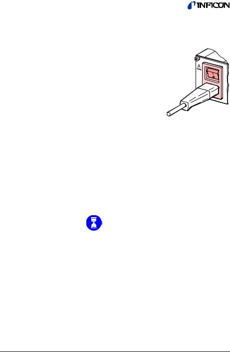
4.2Turning the VGC401 On and Off
Turning the VGC401 on
Turning the VGC401 off
Make sure the VGC401 is correctly installed and the specifications in the Technical Data are met.
The power switch is on the rear of the unit.
Turn the VGC401 on with the power switch (or centrally, via a switched power distributor, if the unit is incorporated in a rack).
After power on, the VGC401 …
•automatically performs a self-test
•identifies the connected gauge
•activates the parameters that were in effect before the last power off
•switches to the Measurement mode
•adapts the parameters if required (if another gauge was previously connected).
Turn the VGC401 off with the power switch (or centrally, via a switched power distributor, if the unit is incorporated in a rack).
Wait at least 10 s before turning the VGC401 on again in order for it to correctly initialize itself.
4.3Operating Modes The VGC401 works in the following operating modes:
•Measurement mode
for displaying measurement values or status messages (→ 28)
•Parameter mode
for entering or displaying parameters (→ 31)
•Test mode
for running internal test programs (→ 47)
•Program transfer mode
for updating the firmware (→ 83)
tinb01e1-f (2011-07) VGC401.om |
27 |
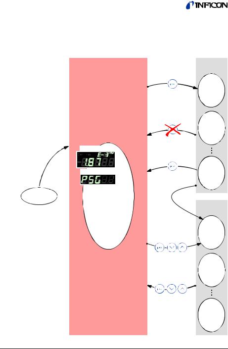
4.4 Measurement Mode The Measurement mode is the standard operating mode of the VGC401. Measurement values and status messages as well as the gauge identification are displayed in this mode.
Measurement mode |
Parameter |
|
mode |
>10 s
Measurement value
Gauge identification
Power on
Test mode
>5 s
>5 s
28 |
tinb01e1-f (2011-07) VGC401.om |

Turning the gauge on and off
Available for: |
|
|
|
Pirani |
|
(PSG) |
|
Pirani/Capacitive |
|
(PCG) |
|
; Cold cathode |
|
(PEG) |
|
Cold cathode/Pirani |
|
(MPG) |
|
; Hot cathode |
|
(BAG) |
|
Hot cathode/Pirani |
|
(BPG, HPG) |
|
Capacitive |
|
(CDG) |
|
Hot cathode/Pirani/Capacitive |
(BCG) |
||
para |
Ö Press key >1 s: |
||
The gauge is |
|||
|
|||
|
turned off. |
||
|
|
is dis- |
|
|
played instead of |
||
|
the measurement |
||
|
value. |
|
|
|
Ö Press key >1 s: |
||
|
The gauge is |
||
para |
turned on. A status |
||
|
message may be |
||
|
displayed instead |
||
of the measurement value:
Pressure p |
|
Measurement |
range |
The high vacuum measurement circuit of these gauges can be activated in both, the Measurement and the Parameter mode (→ 43).
tinb01e1-f (2011-07) VGC401.om |
29 |
 Loading...