


 Loading...
O P E R A T I N G M A N U A L
STM-2
Rate and Thickness Monitor
PN 074-613-P1A

Title Page
O P E R A T I N G M A N U A L
STM-2
Rate and Thickness Monitor
PN 074-613-P1A


 ®
®
www.inficon.com reachus@inficon.com
©2014 INFICON
Trademarks
The trademarks of the products mentioned in this manual are held by the companies that produce them.
Windows® and Microsoft® are registered trademarks of Microsoft Corporation.
Inconel® is a registered trademark of Inco Alloys International, Huntington, WV.
LabVIEWTM is a trademark of National Instruments Corporation.
Sycon InstrumentsTM is a trademark of INFICON, Inc.
All other brand and product names are trademarks or registered trademarks of their respective companies.
Disclaimer
The information contained in this manual is believed to be accurate and reliable. However, INFICON assumes no responsibility for its use and shall not be liable for any special, incidental, or consequential damages related to the use of this product.
Due to our continuing program of product improvements, specifications are subject to change without notice.
Copyright
©2014 All rights reserved.
Reproduction or adaptation of any part of this document without permission is unlawful.


Warranty
WARRANTY AND LIABILITY - LIMITATION: Seller warrants the products manufactured by it, or by an affiliated company and sold by it, and described on the reverse hereof, to be, for the period of warranty coverage specified below, free from defects of materials or workmanship under normal proper use and service. The period of warranty coverage is specified for the respective products in the respective Seller instruction manuals for those products but shall not be less than one (1) year from the date of shipment thereof by Seller. Seller's liability under this warranty is limited to such of the above products or parts thereof as are returned, transportation prepaid, to Seller's plant, not later than thirty (30) days after the expiration of the period of warranty coverage in respect thereof and are found by Seller's examination to have failed to function properly because of defective workmanship or materials and not because of improper installation or misuse and is limited to, at Seller's election, either (a) repairing and returning the product or part thereof, or (b) furnishing a replacement product or part thereof, transportation prepaid by Seller in either case. In the event Buyer discovers or learns that a product does not conform to warranty, Buyer shall immediately notify Seller in writing of such non-conformity, specifying in reasonable detail the nature of such non-conformity. If Seller is not provided with such written notification, Seller shall not be liable for any further damages which could have been avoided if Seller had been provided with immediate written notification.
THIS WARRANTY IS MADE AND ACCEPTED IN LIEU OF ALL OTHER WARRANTIES, EXPRESS OR IMPLIED, WHETHER OF MERCHANTABILITY OR OF FITNESS FOR A PARTICULAR PURPOSE OR OTHERWISE, AS BUYER'S EXCLUSIVE REMEDY FOR ANY DEFECTS IN THE PRODUCTS TO BE SOLD HEREUNDER. All other obligations and liabilities of Seller, whether in contract or tort (including negligence) or otherwise, are expressly EXCLUDED. In no event shall Seller be liable for any costs, expenses or damages, whether direct or indirect, special, incidental, consequential, or other, on any claim of any defective product, in excess of the price paid by Buyer for the product plus return transportation charges prepaid.
No warranty is made by Seller of any Seller product which has been installed, used or operated contrary to Seller's written instruction manual or which has been subjected to misuse, negligence or accident or has been repaired or altered by anyone other than Seller or which has been used in a manner or for a purpose for which the Seller product was not designed nor against any defects due to plans or instructions supplied to Seller by or for Buyer.
This manual is intended for private use by INFICON® Inc. and its customers. Contact INFICON before reproducing its contents.
NOTE: These instructions do not provide for every contingency that may arise in connection with the installation, operation or maintenance of this equipment. Should you require further assistance, please contact INFICON.
www.inficon.com reachus@inficon.com

PN 074-613-P1A
STM-2 Operating Manual
Table Of Contents
Title Page
Trademarks
Disclaimer
Copyright
Declaration Of Conformity
Warranty
Chapter 1
Introduction and Specifications
1.1 Introduction. . . . . . . . . . . . . . . . . . . . . . . . . . . . . . . . . . . . . . . . . . . . . . . . . . 1-1
1.1.1 Related Manuals. . . . . . . . . . . . . . . . . . . . . . . . . . . . . . . . . . . . . . . . . . . . . . 1-1
1.2 Instrument Safety . . . . . . . . . . . . . . . . . . . . . . . . . . . . . . . . . . . . . . . . . . . . . 1-2
1.2.1 Definition of Notes, Cautions and Warnings. . . . . . . . . . . . . . . . . . . . . . . . . 1-2
1.2.2 General Safety Information. . . . . . . . . . . . . . . . . . . . . . . . . . . . . . . . . . . . . . 1-3
1.3 How To Contact INFICON . . . . . . . . . . . . . . . . . . . . . . . . . . . . . . . . . . . . . . 1-4
1.3.1 Returning STM-2 . . . . . . . . . . . . . . . . . . . . . . . . . . . . . . . . . . . . . . . . . . . . . 1-4
1.4 Specifications . . . . . . . . . . . . . . . . . . . . . . . . . . . . . . . . . . . . . . . . . . . . . . . . 1-5
1.4.1 Power . . . . . . . . . . . . . . . . . . . . . . . . . . . . . . . . . . . . . . . . . . . . . . . . . . . . . . 1-5
1.4.2 Operating Environment. . . . . . . . . . . . . . . . . . . . . . . . . . . . . . . . . . . . . . . . . 1-5
1.4.3 Size and Weight . . . . . . . . . . . . . . . . . . . . . . . . . . . . . . . . . . . . . . . . . . . . . . 1-5
1.4.4 Computer Requirements . . . . . . . . . . . . . . . . . . . . . . . . . . . . . . . . . . . . . . . 1-5
1.5 Unpacking and Inspection . . . . . . . . . . . . . . . . . . . . . . . . . . . . . . . . . . . . . . 1-6
1.6 Parts and Options Overview. . . . . . . . . . . . . . . . . . . . . . . . . . . . . . . . . . . . . 1-6
1.6.1 Base Configuration . . . . . . . . . . . . . . . . . . . . . . . . . . . . . . . . . . . . . . . . . . . . 1-6
1.6.2 Accessories . . . . . . . . . . . . . . . . . . . . . . . . . . . . . . . . . . . . . . . . . . . . . . . . . 1-6
1.6.2.1 Oscillator Kit . . . . . . . . . . . . . . . . . . . . . . . . . . . . . . . . . . . . . . . . . . . . . . . . . 1-6
1.6.2.2 Sensors . . . . . . . . . . . . . . . . . . . . . . . . . . . . . . . . . . . . . . . . . . . . . . . . . . . . 1-7
Chapter 2
Installation
2.1 Installation Requirements . . . . . . . . . . . . . . . . . . . . . . . . . . . . . . . . . . . . . . . 2-1
2.1.1 Parts Requirements . . . . . . . . . . . . . . . . . . . . . . . . . . . . . . . . . . . . . . . . . . . 2-1
2.2 System Connections. . . . . . . . . . . . . . . . . . . . . . . . . . . . . . . . . . . . . . . . . . . 2-2
2.2.1 Internal Oscillator . . . . . . . . . . . . . . . . . . . . . . . . . . . . . . . . . . . . . . . . . . . . . 2-2
2.2.2 External Oscillator . . . . . . . . . . . . . . . . . . . . . . . . . . . . . . . . . . . . . . . . . . . . 2-3
2.3 Switching Between Internal and External Oscillator . . . . . . . . . . . . . . . . . . . 2-4
2.4 STM-2 Indicators . . . . . . . . . . . . . . . . . . . . . . . . . . . . . . . . . . . . . . . . . . . . . 2-5
TOC - 1

STM-2 Operating Manual
2.4.1 Power . . . . . . . . . . . . . . . . . . . . . . . . . . . . . . . . . . . . . . . . . . . . . . . . . . . . . . 2-5
2.4.2 USB . . . . . . . . . . . . . . . . . . . . . . . . . . . . . . . . . . . . . . . . . . . . . . . . . . . . . . . 2-5
Chapter 3
STM-2 Software Operation
3.1 Introduction. . . . . . . . . . . . . . . . . . . . . . . . . . . . . . . . . . . . . . . . . . . . . . . . . . 3-1 3.2 Installing INFICON STM-2 Software . . . . . . . . . . . . . . . . . . . . . . . . . . . . . . 3-1 3.2.1 Installing the Protocol Server . . . . . . . . . . . . . . . . . . . . . . . . . . . . . . . . . . . . 3-1 3.2.2 Installing the INFICON STM-2 Software and Device Drivers . . . . . . . . . . . . 3-2 3.2.3 Starting INFICON STM-2 Software . . . . . . . . . . . . . . . . . . . . . . . . . . . . . . . 3-3 3.2.3.1 Starting the Software in Windows XP or Windows 7 . . . . . . . . . . . . . . . . . . 3-3 3.2.3.2 Starting the Software in Windows 8 . . . . . . . . . . . . . . . . . . . . . . . . . . . . . . . 3-3 3.3 STM-2 Window. . . . . . . . . . . . . . . . . . . . . . . . . . . . . . . . . . . . . . . . . . . . . . . 3-4 3.3.1 File Menu . . . . . . . . . . . . . . . . . . . . . . . . . . . . . . . . . . . . . . . . . . . . . . . . . . . 3-6 3.3.1.1 Open Configuration . . . . . . . . . . . . . . . . . . . . . . . . . . . . . . . . . . . . . . . . . . . 3-7 3.3.1.2 Save Configuration. . . . . . . . . . . . . . . . . . . . . . . . . . . . . . . . . . . . . . . . . . . . 3-7 3.3.1.3 Save Configuration As . . . . . . . . . . . . . . . . . . . . . . . . . . . . . . . . . . . . . . . . . 3-7 3.3.1.4 Print . . . . . . . . . . . . . . . . . . . . . . . . . . . . . . . . . . . . . . . . . . . . . . . . . . . . . . . 3-8 3.3.1.5 Screen Image to File . . . . . . . . . . . . . . . . . . . . . . . . . . . . . . . . . . . . . . . . . . 3-8 3.3.2 Edit Menu . . . . . . . . . . . . . . . . . . . . . . . . . . . . . . . . . . . . . . . . . . . . . . . . . . . 3-8 3.3.2.1 Graph Settings . . . . . . . . . . . . . . . . . . . . . . . . . . . . . . . . . . . . . . . . . . . . . . . 3-8 3.3.2.1.1 X Axis & Colors . . . . . . . . . . . . . . . . . . . . . . . . . . . . . . . . . . . . . . . . . . . . . . 3-9 3.3.2.1.2 Rate Tab. . . . . . . . . . . . . . . . . . . . . . . . . . . . . . . . . . . . . . . . . . . . . . . . . . . 3-10 3.3.2.1.3 Thickness Tab . . . . . . . . . . . . . . . . . . . . . . . . . . . . . . . . . . . . . . . . . . . . . . 3-12 3.3.2.1.4 Frequency Tab . . . . . . . . . . . . . . . . . . . . . . . . . . . . . . . . . . . . . . . . . . . . . . 3-14 3.3.2.2 Display Settings . . . . . . . . . . . . . . . . . . . . . . . . . . . . . . . . . . . . . . . . . . . . . 3-16 3.3.2.3 Sample Settings . . . . . . . . . . . . . . . . . . . . . . . . . . . . . . . . . . . . . . . . . . . . . 3-17 3.3.3 Help Menu . . . . . . . . . . . . . . . . . . . . . . . . . . . . . . . . . . . . . . . . . . . . . . . . . 3-18 3.3.3.1 About Window . . . . . . . . . . . . . . . . . . . . . . . . . . . . . . . . . . . . . . . . . . . . . . 3-18 3.3.4 STM-2 Tab . . . . . . . . . . . . . . . . . . . . . . . . . . . . . . . . . . . . . . . . . . . . . . . . . 3-19 3.3.5 Rate Tab. . . . . . . . . . . . . . . . . . . . . . . . . . . . . . . . . . . . . . . . . . . . . . . . . . . 3-20 3.3.6 Thickness Tab . . . . . . . . . . . . . . . . . . . . . . . . . . . . . . . . . . . . . . . . . . . . . . 3-21 3.3.7 Frequency Tab . . . . . . . . . . . . . . . . . . . . . . . . . . . . . . . . . . . . . . . . . . . . . . 3-22
Chapter 4
STM-2 LabVIEW Operation
4.1 Introduction. . . . . . . . . . . . . . . . . . . . . . . . . . . . . . . . . . . . . . . . . . . . . . . . . . 4-1
4.2 Installing the STM-2 LabVIEW Application. . . . . . . . . . . . . . . . . . . . . . . . . . 4-1
4.2.1 Installing the Protocol Server . . . . . . . . . . . . . . . . . . . . . . . . . . . . . . . . . . . . 4-1
4.2.2 Installing the LabVIEW Application and Device Drivers . . . . . . . . . . . . . . . . 4-2
TOC - 2
PN 074-613-P1A
PN 074-613-P1A
STM-2 Operating Manual
4.2.3 Starting the STM-2 LabVIEW Application. . . . . . . . . . . . . . . . . . . . . . . . . . . 4-3 4.2.3.1 Starting the Software in Windows XP or Windows 7 . . . . . . . . . . . . . . . . . . 4-3 4.2.3.2 Starting the Software in Windows 8 . . . . . . . . . . . . . . . . . . . . . . . . . . . . . . . 4-3 4.3 STM-x_win32.VI Window . . . . . . . . . . . . . . . . . . . . . . . . . . . . . . . . . . . . . . . 4-4 4.3.1 Setup . . . . . . . . . . . . . . . . . . . . . . . . . . . . . . . . . . . . . . . . . . . . . . . . . . . . . . 4-6 4.3.1.1 Manual Connection. . . . . . . . . . . . . . . . . . . . . . . . . . . . . . . . . . . . . . . . . . . . 4-8 4.3.1.2 Simulate Mode . . . . . . . . . . . . . . . . . . . . . . . . . . . . . . . . . . . . . . . . . . . . . . . 4-9 4.3.2 Operate. . . . . . . . . . . . . . . . . . . . . . . . . . . . . . . . . . . . . . . . . . . . . . . . . . . . 4-10 4.3.3 Films . . . . . . . . . . . . . . . . . . . . . . . . . . . . . . . . . . . . . . . . . . . . . . . . . . . . . . 4-12 4.3.4 Rate Graph . . . . . . . . . . . . . . . . . . . . . . . . . . . . . . . . . . . . . . . . . . . . . . . . . 4-14 4.3.5 Mass/Thick Graph . . . . . . . . . . . . . . . . . . . . . . . . . . . . . . . . . . . . . . . . . . . 4-15 4.3.6 Frequency Graph . . . . . . . . . . . . . . . . . . . . . . . . . . . . . . . . . . . . . . . . . . . . 4-16 4.3.7 Help/About . . . . . . . . . . . . . . . . . . . . . . . . . . . . . . . . . . . . . . . . . . . . . . . . . 4-18
Chapter 5
Communication
5.1 Communication Protocol . . . . . . . . . . . . . . . . . . . . . . . . . . . . . . . . . . . . . . . 5-1 5.2 Sycon Multi-Drop Protocol (SMDP) . . . . . . . . . . . . . . . . . . . . . . . . . . . . . . . 5-1 5.2.1 Command Format. . . . . . . . . . . . . . . . . . . . . . . . . . . . . . . . . . . . . . . . . . . . . 5-1 5.2.1.1 Checksum. . . . . . . . . . . . . . . . . . . . . . . . . . . . . . . . . . . . . . . . . . . . . . . . . . . 5-4 5.2.1.2 Command Packet Format. . . . . . . . . . . . . . . . . . . . . . . . . . . . . . . . . . . . . . . 5-5 5.2.1.3 Response Packet Format . . . . . . . . . . . . . . . . . . . . . . . . . . . . . . . . . . . . . . . 5-6 5.2.2 Optional Serial Command Mode . . . . . . . . . . . . . . . . . . . . . . . . . . . . . . . . . 5-6 5.2.2.1 Optional Serial Command Format . . . . . . . . . . . . . . . . . . . . . . . . . . . . . . . . 5-7 5.2.2.2 Additional Option to Serial Command . . . . . . . . . . . . . . . . . . . . . . . . . . . . . 5-7 5.3 Communications Commands . . . . . . . . . . . . . . . . . . . . . . . . . . . . . . . . . . . . 5-8
Chapter 6
Troubleshooting and Maintenance
6.1 Troubleshooting Guide . . . . . . . . . . . . . . . . . . . . . . . . . . . . . . . . . . . . . . . . . 6-1
6.1.1 Indicator . . . . . . . . . . . . . . . . . . . . . . . . . . . . . . . . . . . . . . . . . . . . . . . . . . . . 6-1
6.1.2 General STM-2 Troubleshooting . . . . . . . . . . . . . . . . . . . . . . . . . . . . . . . . . 6-2
6.1.3 Troubleshooting Computer Communications . . . . . . . . . . . . . . . . . . . . . . . . 6-7
Chapter 7
Calibration Procedures
7.1 Importance of Density, Tooling and Z-Ratio . . . . . . . . . . . . . . . . . . . . . . . . . 7-1
7.2 Determining Density . . . . . . . . . . . . . . . . . . . . . . . . . . . . . . . . . . . . . . . . . . . 7-1
7.3 Determining Tooling . . . . . . . . . . . . . . . . . . . . . . . . . . . . . . . . . . . . . . . . . . . 7-2
7.4 Laboratory Determination of Z-Ratio . . . . . . . . . . . . . . . . . . . . . . . . . . . . . . 7-3
TOC - 3

STM-2 Operating Manual
Chapter 8
Measurement and Theory
8.1 Basics. . . . . . . . . . . . . . . . . . . . . . . . . . . . . . . . . . . . . . . . . . . . . . . . . . . . . . 8-1
8.1.1 Monitor Crystals . . . . . . . . . . . . . . . . . . . . . . . . . . . . . . . . . . . . . . . . . . . . . . 8-2
8.1.2 Period Measurement Technique . . . . . . . . . . . . . . . . . . . . . . . . . . . . . . . . . 8-4
8.1.3 Z-match Technique . . . . . . . . . . . . . . . . . . . . . . . . . . . . . . . . . . . . . . . . . . . 8-6
Appendix A
Material Table
A.1 Introduction. . . . . . . . . . . . . . . . . . . . . . . . . . . . . . . . . . . . . . . . . . . . . . . . . .A-1
PN 074-613-P1A
TOC - 4
STM-2 Operating Manual
Chapter 1
Introduction and Specifications
1.1 Introduction
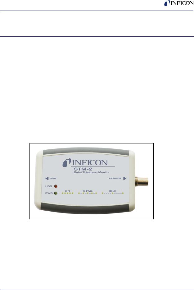
STM-2™ is a USB-powered thin film thickness and rate deposition monitor (see Figure 1-1). STM-2 provides precise control of thickness or mass deposition experiments using a USB connection, Windows® or LabVIEW™ software (provided), and a Windows computer (user supplied).
The STM-2 internal oscillator allows the sensor to be located within 76.2 cm (30 in.) of STM-2. An external oscillator, PN 783-500-013, can be used when the sensor is located farther than 101.6 cm (40 in.) from STM-2.
STM-2 can take ten measurements per second. The measurements are shown on a 0.01Å/s rate display. STM-2 LabVIEW software has an option for multi-layer mode. This mode enables a Layer Stackup pane, displaying a list of process layers. It also enables cumulative substrate thickness to be displayed on the software (see section 4.3.1 on page 4-6).
Figure 1-1 STM-2
PN 074-613-P1A
1.1.1 Related Manuals
Sensors are covered in separate manuals. These manuals are contained in the
Thin Film Manuals CD (PN 074-5000-G1), which is part of the ship kit.
PN 074-154—Bakeable Sensor
PN 074-156—Front Load Sensor, Single/Dual
PN 074-157—Sputtering Sensor
PN 074-609—Cool Drawer Sensor, Single/Dual
1 - 1
STM-2 Operating Manual
1.2 Instrument Safety
1.2.1 Definition of Notes, Cautions and Warnings
When using this manual, please pay attention to the notes, cautions and warnings found throughout. For the purposes of this manual they are defined as follows:
NOTE: Pertinent information that is useful in achieving maximum STM-2 efficiency when followed.
CAUTION
Failure to heed these messages could result in damage to STM-2 or the loss of data.
WARNING
Failure to heed these messages could result in personal injury.
WARNING - Risk Of Electric Shock
Dangerous voltages are present, which could result in personal injury.
PN 074-613-P1A
1 - 2

STM-2 Operating Manual
1.2.2 General Safety Information
CAUTION
STM-2 contains delicate circuitry, susceptible to transient power line voltages. Disconnect the USB cord whenever making any sensor connections or when the case is open.
Refer all maintenance to qualified personnel.
CAUTION
STM-2 may not be suitable for use with RF sputtering systems or other electrically noisy environments.
WARNING
Failure to operate STM-2 in the manner intended by INFICON can circumvent the safety protection provided by the instrument and may result in personal injury.
PN 074-613-P1A
1 - 3

STM-2 Operating Manual
1.3 How To Contact INFICON
Worldwide customer support information is available under Support >> Support Worldwide at www.inficon.com:
Sales and Customer Service
Technical Support
Repair Service
When communicating with INFICON about STM-2, please have the following information readily available:
the Sales Order or Purchase Order number of the STM-2 purchase.
the version of STM-2 software (see section 3.3.3.1 on page 3-18 or section 4.3.7 on page 4-18).
the version of Windows operating system.
adescription of the problem.
an explanation of any corrective action that may have already been attempted.
the exact wording of any error messages that may have been received.
1.3.1Returning STM-2
Do not return any component of STM-2 to INFICON before speaking with a Customer Support Representative and obtaining a Return Material Authorization (RMA) number. STM-2 will not be serviced without an RMA number.
Packages delivered to INFICON without an RMA number will be held until the customer is contacted. This will result in delays in servicing STM-2.
If returning STM-2 with a crystal sensor or another component potentially exposed to process materials, prior to being given an RMA number, a completed Declaration Of Contamination (DOC) form will be required. DOC forms must be approved by INFICON before an RMA number is issued. INFICON may require that the component be sent to a designated decontamination facility, not to the factory.
PN 074-613-P1A
1 - 4

PN 074-613-P1A
STM-2 Operating Manual
1.4 Specifications
Compatible Sensor. . . . . . . . . . . . . . Non-shuttered single QCM sensor Sensor Inputs . . . . . . . . . . . . . . . . . . 1
Sensor Input . . . . . . . . . . . . . . . . . . . Female BNC Measurement Frequency Range . . . 6.0 to 5.0 MHz (fixed) Frequency Resolution . . . . . . . . . . . ± 0.03 Hz @ 6 MHz Measurement Interval. . . . . . . . . . . . 0.10 s
Reference Frequency Stability . . . . . ± 2 ppm Thickness and Rate
Resolution/Measurement . . . . . . . . . ± 0.037 Å @ tooling/density = 100/1 Fundamental frequency = 6 MHz
Thickness Display Resolution . . . . . 1 Å
Interface . . . . . . . . . . . . . . . . . . . . . . USB, 5 m (16.4 ft.) maximum length
1.4.1 Power
Rated Supply Voltage. . . . . . . . . . . . 400 mA, 5 V (dc) USB Isolation Voltage. . . . . . . . . . . . 1000 V
USB Isolation Capacitance. . . . . . . . 300 pF typically
1.4.2 Operating Environment
Usage . . . . . . . . . . . . . . . . . . . . . . . . Indoor use only Operating Temperature . . . . . . . . . . 0 to 50°C (32 to 122°F) Storage Temperature . . . . . . . . . . . . -10 to 60°C (14 to 140°F)
Humidity . . . . . . . . . . . . . . . . . . . . . . Up to 85% RH, non-condensing Altitude . . . . . . . . . . . . . . . . . . . . . . . Up to 2000 meters
Pollution Degree. . . . . . . . . . . . . . . . 2
1.4.3 Size and Weight
Size . . . . . . . . . . . . . . . . . . . . . . . . . 11.4 x 7.6 x 2.5 cm (4.5 x 3 x 1 in.) Weight . . . . . . . . . . . . . . . . . . . . . . . 57 g (2 oz.)
1.4.4 Computer Requirements
Operating system . . . . . . . . . . . . . . . Windows 8, Windows 7, Windows Vista, Windows XP, or Windows 2000
USB Port(s) . . . . . . . . . . . . . . . . . . . One USB 1.1 (or later) port for each STM-2
1 - 5

STM-2 Operating Manual
1.5 Unpacking and Inspection
1Remove STM-2 from its packaging.
2Carefully examine STM-2 for damage that may have occurred during shipping. It is especially important to note obvious rough handling on the outside of the container. Immediately report any damage to the carrier and to INFICON.
NOTE: Do not discard the packaging material until inventory has been taken and installation is successful.
3Refer to the invoice and take inventory.
4To install STM-2, see Chapter 2, Installation.
For additional information or technical assistance, contact INFICON (refer to section 1.3 on page 1-4).
1.6 Parts and Options Overview
1.6.1 Base Configuration
STM-2 with software and cables . . . PN STM-2
1.6.2 Accessories
5 m (16.4 ft.) USB cable. . . . . . . . . . PN 068-0506
15.2cm (6 in.) BNC . . . . . . . . . . . . . PN 755-257-G6
1.6.2.1Oscillator Kit
STM-2 has an internal oscillator, however, an option exists to use an external oscillator kit to interface the sensor to the controller (see section 2.3 on page 2-4).
3 m (10 ft.) Oscillator Kit. . . . . . . . . . PN 783-500-109-10 7.6 m (25 ft.) Oscillator Kit . . . . . . . . PN 783-500-109-25 15.2 m (50 ft.) Oscillator Kit . . . . . . . PN 783-500-109-50 22.9 m (75 ft.) Oscillator Kit . . . . . . . PN 783-500-109-75
PN 074-613-P1A
1 - 6

STM-2 Operating Manual
Oscillator kits include:
Oscillator. . . . . . . . . . . . . . . . . . . PN 783-500-013 15.2 cm (6 in.) BNC cable . . . . . PN 782-902-011 One of the following:
3 m (10 ft.) BNC Cable . . . . . PN 782-902-012-10 7.6 m (25 ft.) BNC Cable . . . PN 782-902-012-25 15.2 m (50 ft.) BNC Cable . . PN 782-902-012-50 22.9 m (75 ft.) BNC Cable . . PN 782-902-012-75
These kits are designed for use with the standard in-vacuum cables ranging in length from 15.2 cm (6 in.) to 78.1 cm (30.75 in.).
1.6.2.2 Sensors
Front Load Single Sensor. . . . . . . . . . . . PN SL-XXXXX
Cool Drawer Single Sensor . . . . . . . . . . PN CDS-XXFXX
Sputtering Sensor. . . . . . . . . . . . . . . . . . PN 750-618-G1 UHV Bakeable Sensor . . . . . . . . . . . . . . PN BK-A0F Low Profile Singe Sensor . . . . . . . . . . . . PN 783-500-042 Low Profile Bakeable Single Sensor . . . PN 783-500-009
NOTE: Low Profile Single Sensors also have options with no cooling lines.
NOTE: "X" in part number indicates customer-selectable option, see www.inficon.com for Sensor Datasheets.
NOTE: Multi-crystal (rotary) sensors and dual sensors should not be used with STM-2.
PN 074-613-P1A
1 - 7

STM-2 Operating Manual
This page is intentionally blank.
PN 074-613-P1A
1 - 8
STM-2 Operating Manual
Chapter 2
Installation
2.1 Installation Requirements
2.1.1Parts Requirements
STM-2 Monitor
One crystal sensor with feedthrough
One oscillator kit for the crystal sensor
NOTE: The oscillator kit is not required when using the internal oscillator.
Quartz crystals appropriate for the application
One Windows computer meeting minimum specifications (refer to section 1.4 on page 1-5).
CAUTION
To maintain proper STM-2 performance, use only
the provided 15.2 cm (6 in.) BNC cable to connect STM-2 or the oscillator to the crystal sensor.
The length of the in-vacuum cable (Front Load and Sputtering sensors) or electrical conduit tube
(Cool Drawer and Bakeable sensors) must not exceed 78.1 cm (30.75 in.).
PN 074-613-P1A
2 - 1
STM-2 Operating Manual
2.2 System Connections
STM-2 can be configured to use either an internal or external oscillator depending on the internal jumpers. The default jumper setting is to use the internal oscillator.
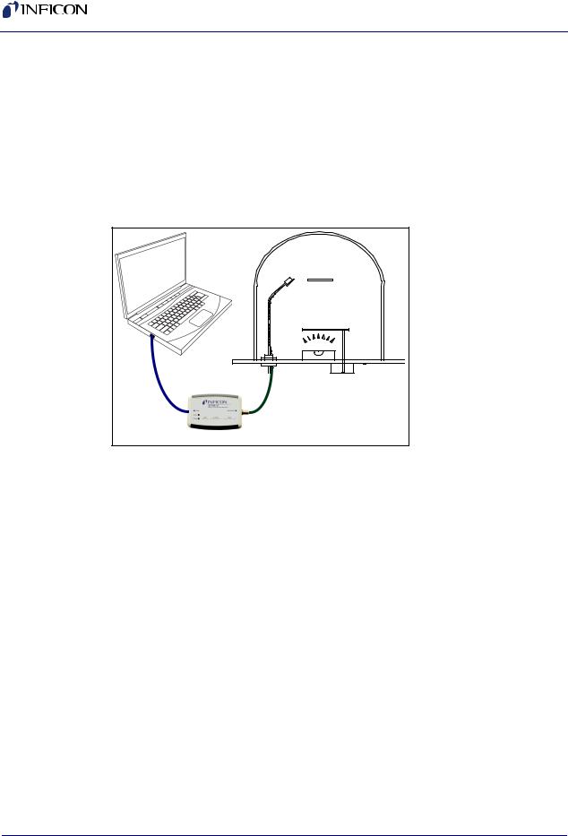
2.2.1 Internal Oscillator
1Connect the (provided) USB cable to a computer USB port and to STM-2.
2Use the (provided) 15.2 cm (6 in.) BNC cable to connect STM-2 to the sensor feedthrough (see Figure 2-1).
Figure 2-1 Internal oscillator
Sensor Substrate
USB
Source 


USB Cable
BNC Cable
Maximum Length 15.2 cm (6 in.)
Jumpers set
for internal oscillator
3 Install and run STM-2 Software or STM-2 LabVIEW Application (see Chapter 3 or Chapter 4).
NOTE: STM-2 Software and STM-2 LabVIEW can be installed and run on the same computer without interference.
4 The PWR indicator on STM-2 illuminates (see section 2.4.1 on page 2-5).
5 |
The USB indicator on STM-2 illuminates (see section 2.4.2 on page 2-5). |
-P1A |
|
PN 074-613 |
|||
|
|
2 - 2
STM-2 Operating Manual
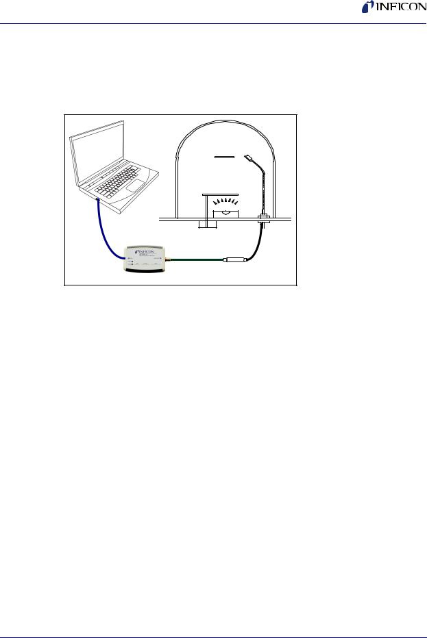
2.2.2 External Oscillator
To use an optional external oscillator, the jumpers inside STM-2 must be repositioned (see section 2.3). The maximum BNC cable length connecting the external oscillator and STM-2 is 22.9 m (75 ft.) (see Figure 2-2).
Figure 2-2 External oscillator
Substrate Sensor
USB


 Source
USB |
|
|
Cable |
|
BNC Cable |
|
|
|
|
|
Maximum Length |
|
|
22.9 m (75 ft.) |
15.2 cm (6 in.) BNC Cable
Jumpers set
for external oscillator
Oscillator 783-500-013
PN 074-613-P1A
2 - 3
STM-2 Operating Manual
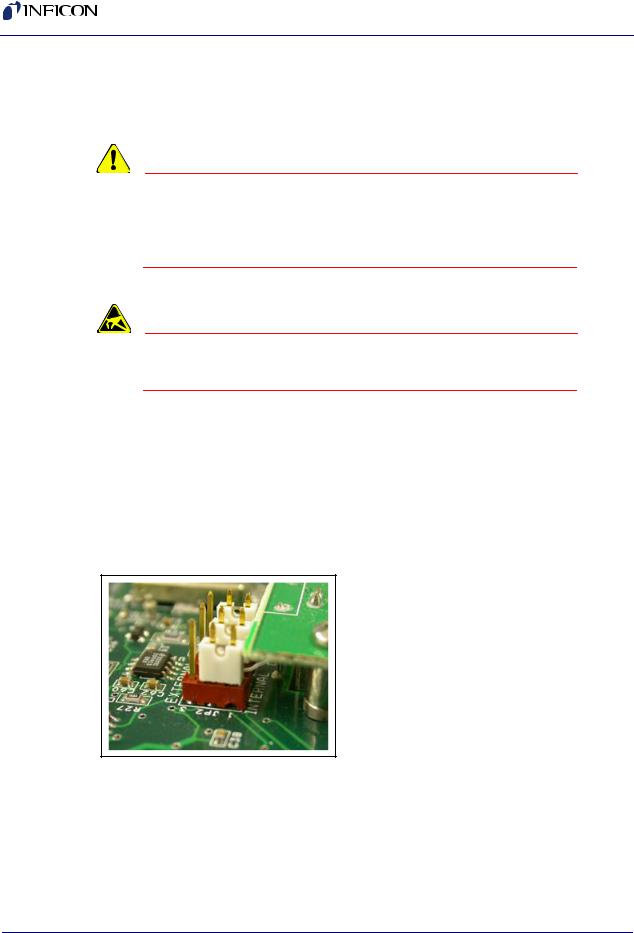
2.3 Switching Between Internal and External Oscillator
Three jumpers must be repositioned inside the STM-2 case to switch between the internal oscillator and an external oscillator.
CAUTION
STM-2 contains delicate circuitry, susceptible to transient power line voltages. Disconnect the USB cord whenever making any sensor connections or when the case is open.
CAUTION - Static Sensitive Device
Observe proper ESD procedures when the STM-2 case is open.
Remove the two phillips screws which secure the back of the case, and remove the back of the case.
Near the BNC connector are three jumpers on the circuit board, labeled Internal and External. Move all three jumpers:
To Internal for internal oscillator operation (see Figure 2-3).
To External for external oscillator operation.
Figure 2-3 Jumpers set for internal oscillator operation
PN 074-613-P1A
2 - 4

PN 074-613-P1A
STM-2 Operating Manual
2.4 STM-2 Indicators
2.4.1 Power
Illuminated . . . . . . . . . . . . . . . . . . . . STM-2 is powered up and is connected to a good crystal.
The host computer has initialized STM-2 by returning a reset status when the software begins communication.
Flashing fast . . . . . . . . . . . . . . . . . . . STM-2 is powered up but cannot detect a good crystal.
Blinking slow
(approximately once per second) . . . STM-2 is powered up and the crystal is good, but the computer application has not initialized STM-2. Once the computer initializes STM-2 the indicator will illuminate continuously (see section 6.1.1 on page 6-1).
Extinguished. . . . . . . . . . . . . . . . . . . STM-2 does not have power. Check the USB connection, and make sure the computer is turned on.
2.4.2 USB
The USB indicator detects communications signal traffic.
Illuminated . . . . . . . . . . . . . . . . . . . . STM-2 is connected and communicating to a host computer. Communications sent/received every 100 ms will cause the indicator to be steadily illuminated.
Flashing . . . . . . . . . . . . . . . . . . . . . . STM-2 is connected and communicating to a host computer. A flashing indicator will correspond to the time elapsed between sent and received communications. A query sent once per second will correspond to the indicator flashing approximately once per second.
Extinguished. . . . . . . . . . . . . . . . . . . STM-2 is not communicating to the computer.
NOTE: STM-x_win32 LabVIEW application software and INFICON STM-2 software will steadily illuminate the indicator due to communications queries sent every 100 ms. User-created software may not steadily illuminate the indicator due a longer time period elapsing between communications queries being sent.
2 - 5

STM-2 Operating Manual
This page is intentionally blank.
PN 074-613-P1A
2 - 6

PN 074-613-P1A
STM-2 Operating Manual
Chapter 3
STM-2 Software Operation
3.1 Introduction
INFICON STM-2 Software is capable of interfacing up to eight STM-2 instruments to display Rate, Thickness, Frequency, and Crystal Life for the connected sensors. STM-2 Software has independent Density, Z-Ratio, and Tooling parameters for each STM-2 to allow for codeposition monitoring capabilities.
3.2 Installing INFICON STM-2 Software
3.2.1Installing the Protocol Server
1Insert the Thin Film Manuals CD into the CD drive on the computer that will be connected to STM-2.
2Click Windows Explorer or
File Explorer >> Computer >> (CD drive letter:) >> Common Software.
3Double click setup_smdp_svr_lv.exe. The Zip Self-Extractor window will display.
4Click Unzip. The SMDP Serial Protocol Server window will display.
5On the Destination Directory pane, click Browse to select the location where all software will be installed.
6Click Next.
7Read the license agreement.
8Click I accept License Agreement(s).
9Click Next.
10Review the summary of information.
11Click Next. Installation Complete will display.
12Click Next. The Setup Wizard pane will display.
13Click Next. The Confirm Installation pane will display.
14Click Next.
15Read the license agreement.
16Click I Agree.
17Click Next. Installation Complete will display.
18Click Close.
19Click Close on the Zip Self-Extractor.
3 - 1

STM-2 Operating Manual
3.2.2Installing the INFICON STM-2 Software and Device Drivers
1Insert the Thin Film Manuals CD into the CD drive of the computer that will be connected to STM-2.
2Click Windows Explorer or File Explorer >> Computer >> (CD drive letter:) >> STM-2.
3Double click STM-2 v1.0.0 Setup.exe. The STM-2 - InstallShield Wizard will display.
4Click Next.
5Review the summary of information.
6Select I accept the terms in the license agreement.
7Click Next.
8Click Change to select the location of the software files to be installed.
9Click Next.
10Click Install.
11Click Finish. The USB Installer - InstallShield Wizard window will display.
12Click Next.
13Review the summary of information.
14Select I accept the terms in the license agreement.
15Click Next.
16Enter User Name and Organization information.
17Click Next.
18Click Install.
19Click Finish. The CP210x USB to UART Bridge Driver Installer window will display.
20Click Next.
21Review the summary of information.
22Select I accept this agreement.
23Click Next.
24Click Finish.
PN 074-613-P1A
3 - 2

PN 074-613-P1A
STM-2 Operating Manual
3.2.3 Starting INFICON STM-2 Software
3.2.3.1 Starting the Software in Windows XP or Windows 7
1Click Start >> All Programs >> INFICON >> STM-2.
2The STM-2 window will display (see Figure 3-1).
Figure 3-1 STM-2 window
3.2.3.2 Starting the Software in Windows 8
1In the Start window, click the STM-2 icon.
2If the icon cannot be found:
2a Click Search >> Apps.
2b Type STM in the Search text box.
2c Click the STM-2 icon.
3 - 3

STM-2 Operating Manual
3.3 STM-2 Window
The STM-2 window displays Serial Number (SN), (Sensor) Name, Rate, Thick(ness) of the film, Zero thickness button, Freq(uency), crystal Life, Density of the film, Z-Ratio, and Tooling for the connected sensor and process material. This window also provides a button to Start, Stop, or Pause/Resume monitoring. Also, the Run Time of the Process, the Run #, a selection for Data Log(ging) to be turned on and off, and the current date and time are displayed. From this window, there is also access to STM-2, Rate, Thickness, and Frequency tabs as well as the File, Edit, and Help menus for customization and configuration (see Figure 3-2).
Figure 3-2 STM-2 window
File menu (see section 3.3.1 on page 3-6)
Edit menu (see section 3.3.2 on page 3-8)
Help menu (see section 3.3.3 on page 3-18)
STM-2 tab (see section 3.3.4 on page 3-19)
Rate tab (see section 3.3.5 on page 3-20)
Thickness tab (see section 3.3.6 on page 3-21)
Frequency tab (see section 3.3.7 on page 3-22)
PN 074-613-P1A
3 - 4
Loading...