


Capacitance Diaphragm Gauge
CDG160D
CDG200D
Operating Manual
Incl. EC Declaration of Conformity
tina53e1-c (2011-11) |
1 |
Product Identification
In all communications with INFICON, please specify the information given on the product nameplate. For convenient reference copy that information into the space provided below.
INFICON AG, LI-9496 Balzers
Model:
PN:
SN:
V W; LPS 
2 |
tina53e1-c (2011-11) |

Validity
This document applies to products of the CDG160D and CDG200D series.
Part numbers of standard products are indicated below. OEM products have other part numbers and different parameter settings (e.g. factory setting of setpoint) as defined in the corresponding ordering information.
Sensor temperature
Switching function
Interface
3Cx1-xxx-xxxx
Receptacle
Flange
Unit
Measurement range (F.S.)
E 160 °C
F 200 °C
2 None
3 2 switching functions
0 none (analog)
1 DeviceNet
2 Profibus
0 Standard B P control
0D-Sub, 9-pin
2D-Sub, 15-pin
1DN 16 ISO-KF
3DN 16 CF-R
9 1/2" tube E 8VCR
H 8VCR long tube
5 Torr (x 133 Pa; x 1.3 mbar)
6 mbar (x 100 Pa)
6 1
7 2
8 5
9 10 A 20 B 50 C 100 D 200 E 500
F 1000 (Torr only) G 1100 (mbar only)
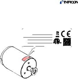
The part number (PN) can be taken from the product nameplate.
tina53e1-c (2011-11) |
3 |

If not indicated otherwise in the legends, the illustrations in this document correspond to gauges with D-Sub 15-pin connector and DN 16 ISO-KF vacuum connection. They apply to the other gauges by analogy.
We reserve the right to make technical changes without prior notice.
Intended Use
The temperature compensated Capacitance Diaphragm Gauges of the CDG160D and CDG200D series are intended for absolute pressure measurement of gases in their respective pressure ranges (→ 3).
The gauges belong to the SKY® Smart Sensors family and can be operated in connection with an INFICON Vacuum Gauge Controller (VGC series) or another appropriate controller.
Functional Principle
A ceramic diaphragm is deflected by pressure. The deflection is measured capacitively and converted into an analog linear output signal by the digital electronics.
The output signal is independent of the gas type.
Very accurate pressure measurement is achieved by heating the sensor to a constant temperature of 160°C or 200 °C which results in a compensation of changes in the ambient conditions and a reduced deposition of process products and by-products in process applications. An integrated baffle protects the sensor against coating.
Trademarks
SKY® |
INFICON GmbH |
VCR® |
Swagelok Marketing Co. |
4 |
tina53e1-c (2011-11) |

Patents
EP 1070239 B1, 1040333 B1
US Patents 6528008, 6591687, 7107855, 7140085
Scope of Delivery
1× gauge CDGxxxD 1× insulation shell
1× pin for adjusting settings via buttons 1× Calibration Test Report
1× Operating Manual German
1× Operating Manual English
tina53e1-c (2011-11) |
5 |

Contents
Product Identification |
2 |
||
Validity |
3 |
||
Intended Use |
4 |
||
Functional Principle |
4 |
||
Trademarks |
4 |
||
Patents |
5 |
||
Scope of Delivery |
5 |
||
1 |
Safety |
8 |
|
1.1 |
|
Symbols Used |
8 |
1.2 |
|
Personnel Qualifications |
8 |
1.3 |
|
General Safety Instructions |
9 |
1.4 |
|
Liability and Warranty |
9 |
2 |
Technical Data |
10 |
|
3 |
Installation |
16 |
|
3.1 |
|
Vacuum Connection |
16 |
3.2 |
|
Power Connection |
20 |
3.2.1 |
D-Sub, 9-pin Connector |
21 |
|
3.2.2 |
D-Sub, 15-pin Connector |
22 |
|
4 |
Operation |
23 |
|
4.1 |
|
Status Indication |
23 |
4.2 |
|
Zeroing the Gauge |
24 |
4.2.1 |
<ZERO> Adjustment |
25 |
|
4.3 |
|
Switching Functions |
29 |
4.4 |
|
Activating the Factory Setting (Factory Reset) |
32 |
4.5 |
|
Diagnostic Port (RS232C Interface) |
33 |
5 |
Deinstallation |
34 |
|
5.1 |
|
Power Connection |
34 |
5.2 |
|
Vacuum connection |
34 |
6 |
Maintenance, Repair |
37 |
|
7 |
Returning the Product |
37 |
|
8 |
Disposal |
38 |
|
9 |
Accessories |
39 |
|
|
|
|
|
6 |
|
tina53e1-c |
(2011-11) |

Further Information |
40 |
ETL Certification |
41 |
EC Declaration of Conformity |
42 |
For cross-references within this document, the symbol (→ XY) is used, for cross-references to further documents, listed under
"Further Information", the symbol (→ [Z]).
tina53e1-c (2011-11) |
7 |

1 Safety
1.1Symbols Used
DANGER
Information on preventing any kind of physical injury.
WARNING
Information on preventing extensive equipment and environmental damage.
Caution
Information on correct handling or use. Disregard can lead to malfunctions or minor equipment damage.
Notice
1.2Personnel Qualifications
Skilled personnel
All work described in this document may only be carried out by persons who have suitable technical training and the necessary experience or who have been instructed by the end-user of the product.
8 |
tina53e1-c (2011-11) |

1.3General Safety Instructions
•Adhere to the applicable regulations and take the necessary precautions for the process media used.
Consider possible reactions with the product materials.
•Adhere to the applicable regulations and take the necessary precautions for all work you are going to do and consider the safety instructions in this document.
•Before beginning to work, find out whether any vacuum components are contaminated. Adhere to the relevant regulations and take the necessary precautions when handling contaminated parts.
Communicate the safety instructions to all other users.
1.4Liability and Warranty
INFICON assumes no liability and the warranty becomes null and void if the end-user or third parties
•disregard the information in this document
•use the product in a non-conforming manner
•make any kind of interventions (modifications, alterations etc.) on the product
•use the product with accessories not listed in the product documentation.
The end-user assumes the responsibility in conjunction with the process media used.
Gauge failures due to contamination or wear and tear are not covered by the warranty.
tina53e1-c (2011-11) |
9 |

2Technical Data

 For further technical data for gauges with DeviceNet and
Profibus interface → [5] and [6].
Measurement range |
→ "Validity" |
Accuracy 1) |
0.4% of reading |
Temperature effect on zero |
0.005% F.S./ °C |
Temperature effect on span |
0.02% of reading / °C |
Resolution |
0.003% F.S. |
Gas type dependence |
none |
Output signal analog |
|
(measurement signal) |
|
Measurement range |
0 … +10 V |
Voltage range |
–5 … +10.24 V |
|
(limited to +10.24 V) |
Relationship voltage-pressure |
linear |
Output impedance |
0 Ω (short-circuit proof) |
Loaded impedance |
>10 kΩ |
Response time2) |
30 ms |
Identification |
|
Resistance RIdent |
13.2 kΩ referenced to |
Voltage |
supply common |
|
≤5 V |
Remote Zero Adjust |
digital input for zero adjust- |
External switching contact |
ment (→ 25) |
30 VDC / <5 mA DC |
1)Non-linearity, hysteresis, repeatability in the calibrated range at 25 °C ambient operating temperature without temperature effects after operation of 2 h.
2)Increase 10 … 90 % F.S.
10 |
tina53e1-c (2011-11) |
Switching functions |
SP1, SP2 |
Setting range |
0 … 99% F.S. (0 … 9.9 V) |
Hysteresis |
1% F.S. |
Relay contact |
30 VDC/ ≤0.5 ADC |
|
floating (n.o.) |
closed |
p ≤ pSP (LED lit solid) |
open |
p ≥ pSP (LED off) |
Switching time |
≤50 ms |
Status relay |
|
Relay contact |
30 VDC/ ≤0.5 ADC |
|
connected to supply com- |
|
mon (pin 5) |
closed |
measurement mode |
|
warning |
open |
no supply voltage |
|
warming up |
|
error |
RS232C interface |
|
Transmission rate |
9600 baud |
Data format |
binary |
|
8 data bits |
|
one stop bit |
|
no parity bit |
|
no handshake |
|
→ "Power Connection" |
For further information on the RS232C interface → [4].
Diagnostic port |
Jack connector, 2.5 mm, |
|
3-pin |
tina53e1-c (2011-11) |
11 |

Supply
DANGER
The gauge may only be connected to power supplies, instruments or control devices that conform to the requirements of a grounded protective extralow voltage (SELV) and limited power source
(LPS), Class 2. The connection to the gauge has to be fused 3).
|
|
Supply voltage |
Class 2 / LPS |
|
|
|
|
at the gauge |
+21 … +30 VDC or |
|
|
|
|
|
±15 V (±5%) |
|
|
|
|
Ripple |
≤1 Vpp |
|
|
|
|
Power consumption |
|
|
|
|
|
while being heated |
|
|
|
|
|
CDG160D |
≤18 W |
|
|
|
|
CDG200D |
≤25 W |
|
|
|
|
at operating |
|
|
|
|
|
CDG160D |
≤12 W |
|
|
|
|
CDG200D |
≤18 W |
|
|
|
|
The gauge is protected against reverse polarity of the supply |
|
||
|
|
voltage and overload. |
|
|
|
|
|
Electrical connection |
|
|
|
|
|
3Cx1-xxx-0xxx |
9-pin D-Sub, male |
|
|
|
|
3Cx1-xxx-2xxx |
15-pin D-Sub, male |
|
|
|
|
Sensor cable for |
|
|
|
|
|
3Cx1-xxx-0xxx |
9-pin plus shielding |
|
|
|
|
3Cx1-xxx-2xxx |
15-pin plus shielding |
|
|
|
|
Cable length |
|
|
|
|
|
Supply voltage 24 V |
≤ 5 m (0.14 mm²/conductor) |
|
|
|
|
|
≤ 8 m (0.25 mm²/conductor) |
|
|
|
|
Supply voltage 30 V |
≤ 9 m (0.14 mm²/conductor) |
|
|
|
|
|
≤17 m (0.25 mm²/conductor) |
|
|
|
|
|
|
|
|
|
|
3) INFICON controllers fulfill this requirement. |
|
||
|
|
|
|
|
|
12 |
|
|
tina53e1-c (2011-11) |
|
|

For longer cables, larger conductor cross-sections are required (Rcable ≤1.0 Ω).
Grounding concept |
→ "Power Connection" |
Materials exposed to vacuum |
ceramics (Al2O3 ≥99.5%), |
|
stainless steel AISI 316L |
Internal volume |
≤4.2 cm3 |
Admissible pressure (absolute) |
|
200 / 500 / 1000 / 1100 F.S. |
3 bar |
1 / 2 / 5 / 10 / 20 / 50 / 100 F.S. |
2 bar |
Bursting pressure (absolute) |
6 bar |
Admissible temperatures |
|
Storage |
–40 °C … +65 °C |
Operation |
+10 °C … +50 °C |
Bakeout |
≤200 °C at the flange |
Relative humidity |
≤80% at temperatures |
|
≤+31 °C, decreasing to 50% |
|
at +40°C |
Use |
indoors only, altitude up to |
|
2000 m NN |
Degree of protection |
IP 40 |
tina53e1-c (2011-11) |
13 |
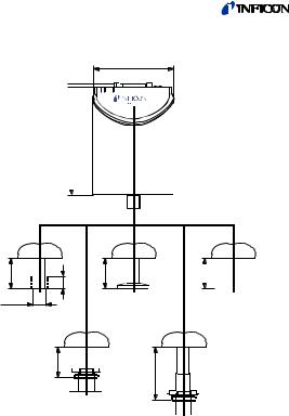
Dimensions [mm]
110.4 3.8
82
31.5 |
13 |
OD½" |
|
|
31.5 |
31.5 DN
16 ISO-KF
54.1
31.5

DN 16 CF-R
8-VCR female
8-VCR long female
Weight |
837 … 897 g |
14 |
tina53e1-c (2011-11) |
 Loading...