


 Loading...
O P E R A T I N G M A N U A L
SQC-310™
Thin Film Deposition Controller
IPN 074-550-P1B

O P E R A T I N G M A N U A L
SQC-310™
Thin Film Deposition Controller
IPN 074-550-P1B


 ®
®
www.inficon.com reachus@inficon.com
©2012 INFICON
Trademarks
The trademarks of the products mentioned in this manual are held by the companies that produce them.
SQC-310™ and INFICON® are trademarks of INFICON GmbH.
Visual Basic®, Windows® and Microsoft® are registered trademarks of Microsoft Corporation.
Oracle® and Java® are registered trademarks of Oracle and/or its affiliates.
All other brand and product names are trademarks or registered trademarks of their respective companies.
Disclaimer
The information contained in this manual is believed to be accurate and reliable. However, INFICON assumes no responsibility for its use and shall not be liable for any special, incidental, or consequential damages related to the use of this product.
Due to our continuing program of product improvements, specifications are subject to change without notice.
Copyright
©2012 All rights reserved.
Reproduction or adaptation of any part of this document without permission is unlawful.

DECLARATION
OF
CONFORMITY
This is to certify that this equipment, designed and manufactured by:
INFICON Inc.
Two Technology Place
East Syracuse, NY 13057
USA
meets the essential safety requirements of the European Union and is placed on the market accordingly. It has been constructed in accordance with good engineering practice in safety matters in force in the Community and does not endanger the safety of persons, domestic animals or property when properly installed and maintained and used in applications for which it was made.
Equipment Description: |
SQC-310 Rate / Thickness Controller (including all options). |
Applicable Directives: |
2006/95/EC (LVD) |
|
2004/108/EC (General EMC) |
|
2002/95/EC (RoHS) |
Applicable Standards: |
|
Safety: |
EN 61010-1:2001 |
Emissions: |
EN 61326-1:1997/A1: 1998/A2: 2001 (Radiated & Conducted Emissions) |
|
Class A: Emissions per Table 3 |
|
(EMC – Measurement, Control & Laboratory Equipment) |
Immunity: |
EN 61326-1:1997/A1: 1998/A2: 2001 (General EMC) |
|
Class A: Immunity per Table A1 |
|
(EMC – Measurement, Control & Laboratory Equipment) |
RoHS: |
Fully compliant |
CE Implementation Date: |
May 2001 (Updated February, 2011) |
Authorized Representative: |
Steve Schill |
Thin Film Business Line Manager
INFICON Inc.
ANY QUESTIONS RELATIVE TO THIS DECLARATION OR TO THE SAFETY OF INFICON'S PRODUCTS SHOULD BE DIRECTED, IN WRITING, TO THE AUTHORIZED REPRESENTATIVE AT THE ABOVE ADDRESS.

Warranty
WARRANTY AND LIABILITY - LIMITATION: Seller warrants the products manufactured by it, or by an affiliated company and sold by it, and described on the reverse hereof, to be, for the period of warranty coverage specified below, free from defects of materials or workmanship under normal proper use and service. The period of warranty coverage is specified for the respective products in the respective Seller instruction manuals for those products but shall not be less than two (2) years from the date of shipment thereof by Seller. Seller's liability under this warranty is limited to such of the above products or parts thereof as are returned, transportation prepaid, to Seller's plant, not later than thirty (30) days after the expiration of the period of warranty coverage in respect thereof and are found by Seller's examination to have failed to function properly because of defective workmanship or materials and not because of improper installation or misuse and is limited to, at Seller's election, either (a) repairing and returning the product or part thereof, or (b) furnishing a replacement product or part thereof, transportation prepaid by Seller in either case. In the event Buyer discovers or learns that a product does not conform to warranty, Buyer shall immediately notify Seller in writing of such non-conformity, specifying in reasonable detail the nature of such non-conformity. If Seller is not provided with such written notification, Seller shall not be liable for any further damages which could have been avoided if Seller had been provided with immediate written notification.
THIS WARRANTY IS MADE AND ACCEPTED IN LIEU OF ALL OTHER WARRANTIES, EXPRESS OR IMPLIED, WHETHER OF MERCHANTABILITY OR OF FITNESS FOR A PARTICULAR PURPOSE OR OTHERWISE, AS BUYER'S EXCLUSIVE REMEDY FOR ANY DEFECTS IN THE PRODUCTS TO BE SOLD HEREUNDER. All other obligations and liabilities of Seller, whether in contract or tort (including negligence) or otherwise, are expressly EXCLUDED. In no event shall Seller be liable for any costs, expenses or damages, whether direct or indirect, special, incidental, consequential, or other, on any claim of any defective product, in excess of the price paid by Buyer for the product plus return transportation charges prepaid.
No warranty is made by Seller of any Seller product which has been installed, used or operated contrary to Seller's written instruction manual or which has been subjected to misuse, negligence or accident or has been repaired or altered by anyone other than Seller or which has been used in a manner or for a purpose for which the Seller product was not designed nor against any defects due to plans or instructions supplied to Seller by or for Buyer.
This manual is intended for private use by INFICON® Inc. and its customers. Contact INFICON before reproducing its contents.
NOTE: These instructions do not provide for every contingency that may arise in connection with the installation, operation or maintenance of this equipment. Should you require further assistance, please contact INFICON.
www.inficon.com reachus@inficon.com

IPN 074-550-P1B
SQC-310 Operating Manual
Table Of Contents
Trademarks
Disclaimer
Copyright
Chapter 1
Quick Start
1.1 Introduction. . . . . . . . . . . . . . . . . . . . . . . . . . . . . . . . . . . . . . . . . . . . . . . . . . 1-1
1.2 Front Panel . . . . . . . . . . . . . . . . . . . . . . . . . . . . . . . . . . . . . . . . . . . . . . . . . . 1-2
1.3 Rear Panel . . . . . . . . . . . . . . . . . . . . . . . . . . . . . . . . . . . . . . . . . . . . . . . . . . 1-3
1.4 System Connections. . . . . . . . . . . . . . . . . . . . . . . . . . . . . . . . . . . . . . . . . . . 1-4
1.5 Installation . . . . . . . . . . . . . . . . . . . . . . . . . . . . . . . . . . . . . . . . . . . . . . . . . . 1-5
1.6 Menus. . . . . . . . . . . . . . . . . . . . . . . . . . . . . . . . . . . . . . . . . . . . . . . . . . . . . . 1-6
1.7 Thin Film Deposition Overview. . . . . . . . . . . . . . . . . . . . . . . . . . . . . . . . . . . 1-7
1.8 Building a Process . . . . . . . . . . . . . . . . . . . . . . . . . . . . . . . . . . . . . . . . . . . . 1-8
1.9 Depositing a Film . . . . . . . . . . . . . . . . . . . . . . . . . . . . . . . . . . . . . . . . . . . . 1-12
Chapter 2
Operation
2.1 Introduction. . . . . . . . . . . . . . . . . . . . . . . . . . . . . . . . . . . . . . . . . . . . . . . . . . 2-1
2.2 Definitions. . . . . . . . . . . . . . . . . . . . . . . . . . . . . . . . . . . . . . . . . . . . . . . . . . . 2-1
2.3 Defining a Film . . . . . . . . . . . . . . . . . . . . . . . . . . . . . . . . . . . . . . . . . . . . . . . 2-2
2.4 Defining a Process . . . . . . . . . . . . . . . . . . . . . . . . . . . . . . . . . . . . . . . . . . . . 2-5
2.5 Defining a Layer . . . . . . . . . . . . . . . . . . . . . . . . . . . . . . . . . . . . . . . . . . . . . . 2-7
2.6 Sensor and Source Setup . . . . . . . . . . . . . . . . . . . . . . . . . . . . . . . . . . . . . . 2-8
2.7 Running a Process . . . . . . . . . . . . . . . . . . . . . . . . . . . . . . . . . . . . . . . . . . . . 2-9
2.8 Loop Tuning . . . . . . . . . . . . . . . . . . . . . . . . . . . . . . . . . . . . . . . . . . . . . . . . 2-13
2.9 Troubleshooting . . . . . . . . . . . . . . . . . . . . . . . . . . . . . . . . . . . . . . . . . . . . . 2-15
Chapter 3
Menus
3.1 Introduction. . . . . . . . . . . . . . . . . . . . . . . . . . . . . . . . . . . . . . . . . . . . . . . . . . 3-1
3.2 Main Screen, Menu 1 . . . . . . . . . . . . . . . . . . . . . . . . . . . . . . . . . . . . . . . . . . 3-2
3.3 Main Screen, Menu 2 . . . . . . . . . . . . . . . . . . . . . . . . . . . . . . . . . . . . . . . . . . 3-2
3.4 Main Screen, Menu 3 . . . . . . . . . . . . . . . . . . . . . . . . . . . . . . . . . . . . . . . . . . 3-3
3.5 Quick Edit Menu . . . . . . . . . . . . . . . . . . . . . . . . . . . . . . . . . . . . . . . . . . . . . . 3-4
3.6 Process Menus. . . . . . . . . . . . . . . . . . . . . . . . . . . . . . . . . . . . . . . . . . . . . . . 3-6
TOC - 1

SQC-310 Operating Manual
3.7 Layer Edit Menu . . . . . . . . . . . . . . . . . . . . . . . . . . . . . . . . . . . . . . . . . . . . . . 3-8
3.8 Layer Copy, Insert and Delete Menus . . . . . . . . . . . . . . . . . . . . . . . . . . . . 3-10
3.9 Film Menus. . . . . . . . . . . . . . . . . . . . . . . . . . . . . . . . . . . . . . . . . . . . . . . . . 3-13
3.10 Film Edit Menu . . . . . . . . . . . . . . . . . . . . . . . . . . . . . . . . . . . . . . . . . . . . . . 3-14
3.10.1 Film Conditioning Menu . . . . . . . . . . . . . . . . . . . . . . . . . . . . . . . . . . . . . . . 3-16
3.10.2 Film Deposit Controls Menu . . . . . . . . . . . . . . . . . . . . . . . . . . . . . . . . . . . . 3-17
3.10.3 Film Configure Sensor Menu . . . . . . . . . . . . . . . . . . . . . . . . . . . . . . . . . . . 3-18
3.11 System Menu . . . . . . . . . . . . . . . . . . . . . . . . . . . . . . . . . . . . . . . . . . . . . . . 3-19
3.11.1 Input and Relay Menus . . . . . . . . . . . . . . . . . . . . . . . . . . . . . . . . . . . . . . . 3-22
3.11.2 Logic Menu. . . . . . . . . . . . . . . . . . . . . . . . . . . . . . . . . . . . . . . . . . . . . . . . . 3-25
3.11.2.1 Entering a Logic Statement . . . . . . . . . . . . . . . . . . . . . . . . . . . . . . . . . . . . 3-26
3.11.2.2 Logic Statement Conditions ("IF") . . . . . . . . . . . . . . . . . . . . . . . . . . . . . . . 3-26
3.11.2.3 Logic Statement Actions ("THEN"). . . . . . . . . . . . . . . . . . . . . . . . . . . . . . . 3-29
3.11.3 Sensors and Sources Menu . . . . . . . . . . . . . . . . . . . . . . . . . . . . . . . . . . . . 3-31
3.11.3.1 Sensor Setup . . . . . . . . . . . . . . . . . . . . . . . . . . . . . . . . . . . . . . . . . . . . . . . 3-31
3.11.3.2 Source Setup . . . . . . . . . . . . . . . . . . . . . . . . . . . . . . . . . . . . . . . . . . . . . . . 3-34
Chapter 4
Maintenance & Accessories
4.1 Introduction. . . . . . . . . . . . . . . . . . . . . . . . . . . . . . . . . . . . . . . . . . . . . . . . . . 4-1
4.2 Cleaning . . . . . . . . . . . . . . . . . . . . . . . . . . . . . . . . . . . . . . . . . . . . . . . . . . . . 4-1
4.3 Software Upgrades. . . . . . . . . . . . . . . . . . . . . . . . . . . . . . . . . . . . . . . . . . . . 4-1
4.4 Clearing the Memory . . . . . . . . . . . . . . . . . . . . . . . . . . . . . . . . . . . . . . . . . . 4-1
4.5 Half Rack Adapter Installation . . . . . . . . . . . . . . . . . . . . . . . . . . . . . . . . . . . 4-3
4.6 Full Rack Extender Installation. . . . . . . . . . . . . . . . . . . . . . . . . . . . . . . . . . . 4-3
4.7 Handheld Remote Controller . . . . . . . . . . . . . . . . . . . . . . . . . . . . . . . . . . . . 4-4
Chapter 5
Communications
5.1 Introduction. . . . . . . . . . . . . . . . . . . . . . . . . . . . . . . . . . . . . . . . . . . . . . . . . . 5-1
5.2 SQC-310 Comm.exe . . . . . . . . . . . . . . . . . . . . . . . . . . . . . . . . . . . . . . . . . . 5-1
5.2.1 Communications Protocol . . . . . . . . . . . . . . . . . . . . . . . . . . . . . . . . . . . . . . 5-1
5.3 SQC-310 Commands . . . . . . . . . . . . . . . . . . . . . . . . . . . . . . . . . . . . . . . . . . 5-3
5.3.1 Get Model. . . . . . . . . . . . . . . . . . . . . . . . . . . . . . . . . . . . . . . . . . . . . . . . . . . 5-3
5.3.2 Get/Set Film Parameters . . . . . . . . . . . . . . . . . . . . . . . . . . . . . . . . . . . . . . . 5-3
5.3.3 Get/Set System Parameters. . . . . . . . . . . . . . . . . . . . . . . . . . . . . . . . . . . . . 5-5
5.3.4 Get/Set Process Parameters . . . . . . . . . . . . . . . . . . . . . . . . . . . . . . . . . . . . 5-6
5.3.5 Get/Set Layer Parameters . . . . . . . . . . . . . . . . . . . . . . . . . . . . . . . . . . . . . . 5-7
5.3.6 Delete All Layers . . . . . . . . . . . . . . . . . . . . . . . . . . . . . . . . . . . . . . . . . . . . . 5-8
5.3.7 Get/Set Material Parameters . . . . . . . . . . . . . . . . . . . . . . . . . . . . . . . . . . . . 5-9
TOC - 2
IPN 074-550-P1B
IPN 074-550-P1B
SQC-310 Operating Manual
5.3.8 Get/Set Input & Relay Parameters . . . . . . . . . . . . . . . . . . . . . . . . . . . . . . . . 5-9
5.3.9 Get/Set Sensor, Source, Relay Parameters. . . . . . . . . . . . . . . . . . . . . . . . 5-11
5.3.10 Get/Set Logic Statement Parameters . . . . . . . . . . . . . . . . . . . . . . . . . . . . 5-13
5.3.11 Get Num Channels . . . . . . . . . . . . . . . . . . . . . . . . . . . . . . . . . . . . . . . . . . . 5-14
5.3.12 Get Readings . . . . . . . . . . . . . . . . . . . . . . . . . . . . . . . . . . . . . . . . . . . . . . . 5-14
5.3.13 Get Sensor Rate. . . . . . . . . . . . . . . . . . . . . . . . . . . . . . . . . . . . . . . . . . . . . 5-14
5.3.14 Get Output Rate . . . . . . . . . . . . . . . . . . . . . . . . . . . . . . . . . . . . . . . . . . . . . 5-15
5.3.15 Get Sensor Thickness . . . . . . . . . . . . . . . . . . . . . . . . . . . . . . . . . . . . . . . . 5-15
5.3.16 Get Output Thickness. . . . . . . . . . . . . . . . . . . . . . . . . . . . . . . . . . . . . . . . . 5-15
5.3.17 Get Sensor Frequency/Crystal Life . . . . . . . . . . . . . . . . . . . . . . . . . . . . . . 5-15
5.3.18 Get Output Deviation . . . . . . . . . . . . . . . . . . . . . . . . . . . . . . . . . . . . . . . . . 5-16
5.3.19 Get/Set Output Power . . . . . . . . . . . . . . . . . . . . . . . . . . . . . . . . . . . . . . . . 5-16
5.3.20 Set Active Process . . . . . . . . . . . . . . . . . . . . . . . . . . . . . . . . . . . . . . . . . . . 5-16
5.3.21 Set Run State . . . . . . . . . . . . . . . . . . . . . . . . . . . . . . . . . . . . . . . . . . . . . . . 5-17
5.3.22 Get Run State. . . . . . . . . . . . . . . . . . . . . . . . . . . . . . . . . . . . . . . . . . . . . . . 5-17
5.3.23 Start Download/Upload Session. . . . . . . . . . . . . . . . . . . . . . . . . . . . . . . . . 5-18
5.3.24 Stop Download/Upload Session . . . . . . . . . . . . . . . . . . . . . . . . . . . . . . . . . 5-18
5.4 CRC Examples . . . . . . . . . . . . . . . . . . . . . . . . . . . . . . . . . . . . . . . . . . . . . . 5-18
5.4.1 Visual Basic® 5/6 . . . . . . . . . . . . . . . . . . . . . . . . . . . . . . . . . . . . . . . . . . . . 5-19
5.4.2 Java®. . . . . . . . . . . . . . . . . . . . . . . . . . . . . . . . . . . . . . . . . . . . . . . . . . . . . . . . . . . . . . . . . . . .5-21
5.4.3 C++. . . . . . . . . . . . . . . . . . . . . . . . . . . . . . . . . . . . . . . . . . . . . . . . . . . . . . . 5-21
Appendix A
Material Table
A.1 Introduction. . . . . . . . . . . . . . . . . . . . . . . . . . . . . . . . . . . . . . . . . . . . . . . . . .A-1
Appendix B
Specifications
B.1 Measurement . . . . . . . . . . . . . . . . . . . . . . . . . . . . . . . . . . . . . . . . . . . . . . . .B-1
B.2 Source . . . . . . . . . . . . . . . . . . . . . . . . . . . . . . . . . . . . . . . . . . . . . . . . . . . . .B-1
B.3 Digital I/O . . . . . . . . . . . . . . . . . . . . . . . . . . . . . . . . . . . . . . . . . . . . . . . . . . .B-1
B.4 General Specifications . . . . . . . . . . . . . . . . . . . . . . . . . . . . . . . . . . . . . . . . .B-2
B.5 Display . . . . . . . . . . . . . . . . . . . . . . . . . . . . . . . . . . . . . . . . . . . . . . . . . . . . .B-2
B.6 Process Parameters . . . . . . . . . . . . . . . . . . . . . . . . . . . . . . . . . . . . . . . . . . .B-2
B.7 Layer Parameters . . . . . . . . . . . . . . . . . . . . . . . . . . . . . . . . . . . . . . . . . . . . .B-3
B.8 Film Parameters . . . . . . . . . . . . . . . . . . . . . . . . . . . . . . . . . . . . . . . . . . . . . .B-3
TOC - 3

SQC-310 Operating Manual
Appendix C
I/O Connections
C.1 Introduction. . . . . . . . . . . . . . . . . . . . . . . . . . . . . . . . . . . . . . . . . . . . . . . . . .C-1 C.2 Interfacing to a INFICON CI-100 Indexer . . . . . . . . . . . . . . . . . . . . . . . . . . .C-2 C.2.1 BCD I/O . . . . . . . . . . . . . . . . . . . . . . . . . . . . . . . . . . . . . . . . . . . . . . . . . . . .C-2 C.2.2 Binary I/O . . . . . . . . . . . . . . . . . . . . . . . . . . . . . . . . . . . . . . . . . . . . . . . . . .C-3 C.3 Interfacing to a MDC E-Beam Sweep Controller . . . . . . . . . . . . . . . . . . . . .C-4 C.3.1 BCD I/O . . . . . . . . . . . . . . . . . . . . . . . . . . . . . . . . . . . . . . . . . . . . . . . . . . . .C-4
IPN 074-550-P1B
TOC - 4
IPN 074-550-P1B
SQC-310 Operating Manual
Chapter 1
Quick Start
1.1 Introduction
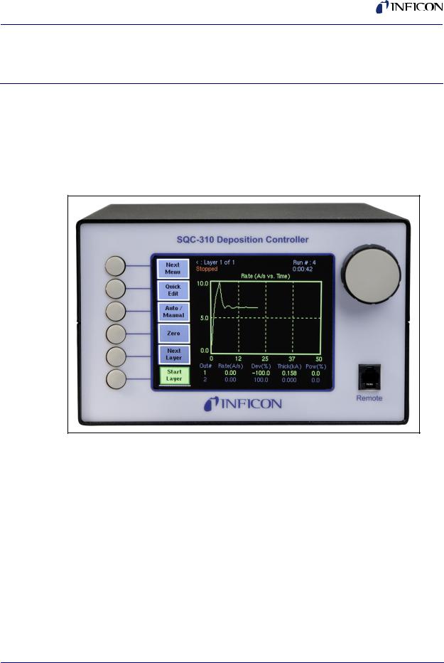
INFICON SQC-310 series instruments are multi-channel QCM-based deposition controllers. They provide a unique combination of accuracy and powerful features in a compact, low cost instrument.
Figure 1-1 SQC-310C
The standard SQC-310 measures up to two quartz crystal sensors, and controls up to two evaporation sources. Eight process control relays and eight digital inputs are included to support a broad range of external devices. The number of sensors, outputs, and digital I/O can be doubled with an optional expansion card. The SQC-310C co-deposition instrument allows simultaneous deposition of up to four materials. RS-232 and USB communications are standard, with Ethernet optional.
NOTE: Both the SQC-310 and SQC-310C are referred to as the SQC-310 in this manual. If there is a reason to distinguish between the two models, the SQC-310 or SQC-310C model number will be called out.
This chapter will aid you in the initial setup and operation of your system. Please review the entire manual for detailed operational, programming, and safety information.
1 - 1
SQC-310 Operating Manual
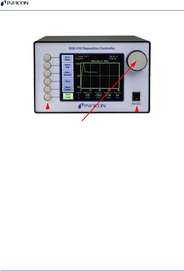
1.2 Front Panel
Figure 1-2 Front Panel Controls
|
|
|
|
|
|
|
|
|
|
|
|
|
|
|
|
|
|
|
|
|
|
|
|
Soft Keys |
Control Knob |
Remote |
Jack |
|
|||
|
|
|
|
|
|||
Table 1-1 Front Panel Controls |
|
|
|
|
|||
|
|
|
|
|
|
|
|
SoftKeys |
Provide access to instrument operations and setup menus. The |
||||||
|
|
|
functions of the SoftKeys change to adapt to different operations |
||||
|
|
|
and are displayed on the left of the screen. |
||||
|
|
|
|
|
|
|
|
Control |
Used to adjust values and select menu items. Pushing the control |
||||||
Knob |
knob stores the current setting and moves to the next, similar to a |
||||||
|
|
|
keyboard’s Enter key. |
|
|
|
|
|
|
|
|
|
|
|
|
Remote |
Connection jack for the optional handheld remote controller. |
||||||
Jack |
|
|
|
|
|
||
|
|
|
|
|
|
|
|
IPN 074-550-P1B
1 - 2
IPN 074-550-P1B
SQC-310 Operating Manual
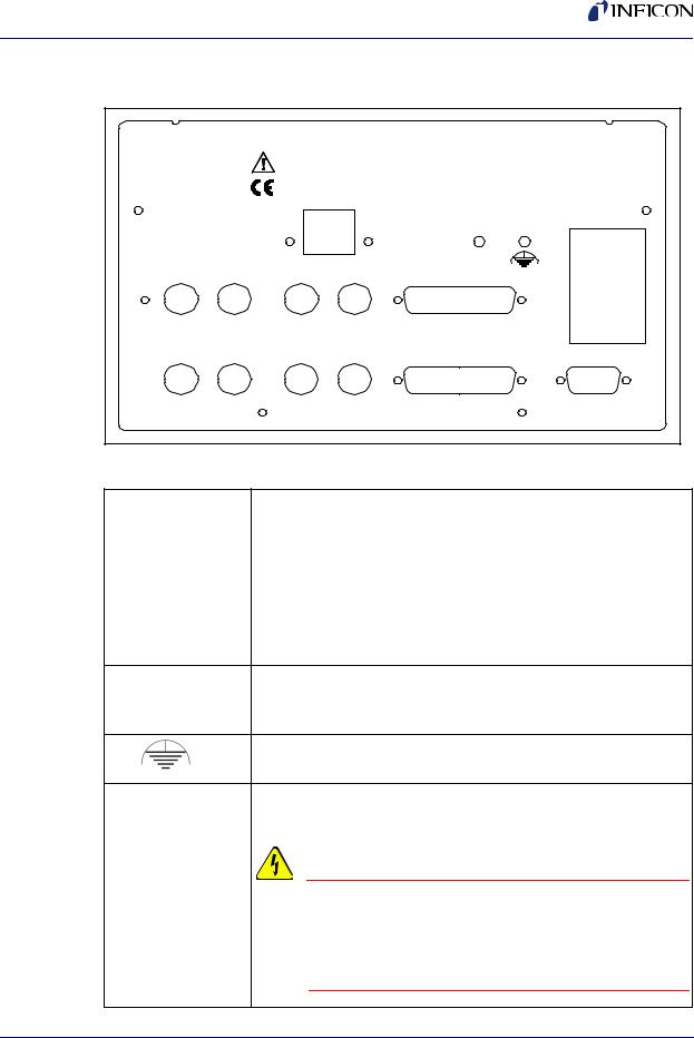
1.3 Rear Panel
Figure 1-3 Rear Panel
|
|
SQC-310 Deposition Controller |
|
|
|
|
|
Serial No. |
|
|
|
|
|
USB/Ethernet |
|
100-120/200-240 V~ |
|
|
|
|
50/60 Hz |
||
|
|
|
|
|
25 VA |
Sensor 3 |
Sensor 4 |
Output 3 |
Output 4 |
I/O9-16 |
|
Sensor 1 |
Sensor 2 |
Output 1 |
Output 2 |
I/O1-8 |
Fuse T.5A 250V |
|
|
|
|
|
|
|
|
|
|
|
RS-232 |
Table 1-2 Rear Panel Connections
Sensor 1 & 2 |
Connects to the oscillator. See section 1.4 on page 1-4. |
|
|
Output 1 & 2 |
Connects the SQC-310 output to your evaporation supply control |
|
input (see next section). |
|
|
I/O (1-8) |
Connects 8 relays and 8 digital inputs to external equipment for |
|
process control. See Appendix C. |
|
|
RS-232 |
Connects to a computer for programming and data acquisition. |
USB or Ethernet |
RS-232 and USB are standard. Ethernet option replaces USB. |
Sensor 3 & 4, Increases the number of input, output, and digital I/O connections Output 3 & 4, when the optional expansion card is installed.
I/O 9-16
Measurement ground terminal useful for common system and cable grounding.
Power Input and |
Connects to mains power. The SQC-310 automatically detects |
Fuse |
main voltages of 100-120 and 200-240 V (ac), 50/60 Hz |
WARNING - Risk Of Electric Shock
For continued protection, replace fuses with the proper type and rating. Use power cords only of the specified type and rating, attached to a properly grounded receptacle.
1 - 3
SQC-310 Operating Manual
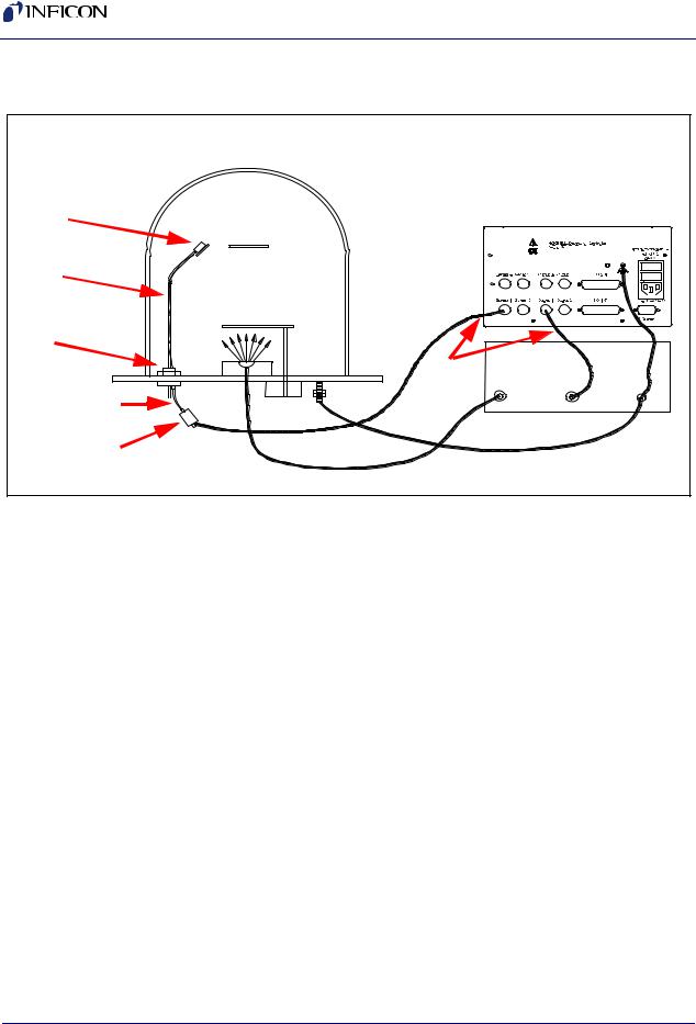
1.4 System Connections
Figure 1-4 |
System Connections |
|
|
Sensor |
|
|
|
In-Vac |
|
|
|
Cable |
|
|
|
|
Source |
|
|
|
Shutter |
|
|
Feedthrough |
|
|
|
|
BNC |
Evaporation Supply |
|
|
Cables |
|
|
6 in. BNC Cable |
Output |
Control Input |
|
|
Oscillator |
Ground Wire |
|
|
Table 1-3 System Components |
|
|
Sensor |
Holds the quartz crystal used to measure rate and thickness. |
|
Crystals must be replaced occasionally. |
|
|
In-Vac Cable |
A coaxial cable that connects the sensor to the feedthrough. |
|
|
Feedthrough |
Provides isolation between vacuum and atmosphere for electrical |
|
and cooling lines. |
|
|
6” BNC Cable |
Provides a flexible connection from the feedthrough to the |
|
oscillator. Keep this cable as short as possible. |
|
|
Oscillator |
Contains the electronics to operate the quartz crystal. Total cable |
|
length to the crystal should be under 40 in. |
|
|
Sensor Input |
Connects the oscillator to the SQC-310 sensor input. Lengths up |
BNC Cable |
to 100 ft. are acceptable. |
|
|
Control Output |
Connects the SQC-310 output to the evaporation source’s control |
BNC Cable |
voltage input. Keep the length under 10 ft.. |
|
|
Ground Wire |
A wire, typically braided, that connects the vacuum system to the |
|
SQC-310 ground terminal. Important for noise rejection. |
|
|
IPN 074-550-P1B
1 - 4
IPN 074-550-P1B
SQC-310 Operating Manual
1.5 Installation
CAUTION
Care should be exercised to route SQC-310 cables as far as practical from other cables that carry high voltages or generate noise. This includes other line voltage cables, wires to heaters that are SCR-controlled, and cables to source power supplies that may conduct high transient currents during arc down conditions.
Table 1-4 Installation
Rack |
The SQC-310 occupies a 5.25 in. high, half-rack space.. An |
Installation |
optional installation kit (P/N 782-900-007) is available to adapt to a |
|
full rack (see section 4.6 on page 4-3 ). |
|
|
Power |
The SQC-310 automatically detects main voltages of 100-120 and |
Connection |
200-240 V (ac), 50/60Hz. |
|
WARNING - Risk Of Electric Shock |
|
||
|
|
|
|
|
|
|
|
Verify that the power cable provided is |
|
|
|
|
connected to a properly grounded mains |
|
|
|
|
receptacle. |
|
|
|
|
|
|
|
|
|
||
Sensor Input |
Connect the BNC cables and oscillators from your vacuum |
|
||
Connections |
chamber feedthrough to the desired SQC-310 sensor inputs. See |
|
||
|
the previous section for cabling details. |
|
||
|
|
|
||
Source Output |
Connect the BNC cables from the SQC-310 output connectors to |
|
||
Connections |
your evaporation supply control input. Consult your Power Supply |
|
||
|
operator’s manual for control input wiring instructions. |
|
||
|
|
|
||
Digital I/O |
Refer to Appendix C for details on wiring digital I/O to the SQC-310 |
|
||
Connections |
Relay I/O connectors. |
|
||
|
|
|
||
Computer |
If you want to collect data or program the SQC-310, attach a |
|
||
Connection |
straight-thru RS-232 cable from the RS-232 connector to your |
|
||
|
computer’s serial port. |
|
||
|
You can also communicate via USB using a standard USB cable. If |
|
||
|
you ordered the Ethernet option, the USB connection is replaced |
|
||
|
with an RJ-45 Ethernet connector. |
|
||
1 - 5

SQC-310 Operating Manual
1.6 Menus
At power up the SQC-310 briefly displays the model number (SQC-310 or SQC-310C) and firmware version information, then the Main screen. See Figure 1-5.
NOTE: If you are prompted for a password, use the switches along the left of the screen to enter the password. The top switch is “1”, the bottom switch is “6.” The Control Knob switch is "7." See section 5.3.3, Get/Set System Parameters, on page 5-5 for password setup information.
Figure 1-5 Main Screen
|
|
|
|
|
|
|
|
|
|
|
|
|
|
|
|
|
|
|
|
|
|
|
|
|
|
|
|
|
|
|
|
|
Next |
Process 1 : Layer 1 of 1 |
|
|
|
|
|
|
|
|
|
|
|
|
Run # :0 |
|
|||||||||||||||
|
Stopped |
|
|
|
|
|
|
|
|
|
|
|
|
|
|
0:00:00 |
|
|
|
|
|
|
|||||||||
|
Menu |
100.0 |
|
|
|
|
|
|
|
Power ( |
% vs. Time) |
|
|
|
|
|
|
||||||||||||||
|
|
|
|
|
|
|
|
|
|
|
|
|
|
|
|
|
|
|
|
|
|
|
|
|
|
|
|
|
|
|
|
|
Quick |
|
|
|
|
|
|
|
|
|
|
|
|
|
|
|
|
|
|
|
|
|
|
|
|
|
|
|
|
|
|
|
|
|
|
|
|
|
|
|
|
|
|
|
|
|
|
|
|
|
|
|
|
|
|
|
|
|
|
|
|
|
|
|
|
|
|
|
|
|
|
|
|
|
|
|
|
|
|
|
|
|
|
|
|
|
|
|
|
|
|
|
|
|
|
|
Edit |
|
|
|
|
|
|
|
|
|
|
|
|
|
|
|
|
|
|
|
|
|
|
|
|
|
|
|
|
|
|
|
|
|
|
|
|
|
|
|
|
|
|
|
|
|
|
|
|
|
|
|
|
|
|
|
|
|
|
|
|
|
|
|
|
|
|
|
|
|
|
|
|
|
|
|
|
|
|
|
|
|
|
|
|
|
|
|
|
|
|
|
|
|
|
|
Auto / |
50.0 |
|
|
|
|
|
|
|
|
|
|
|
|
|
|
|
|
|
|
|
|
|
|
|
|
|
|
|
|
|
|
|
|
|
|
|
|
|
|
|
|
|
|
|
|
|
|
|
|
|
|
|
|
|
|
|
|
|
|
|
||
|
Manual |
|
|
|
|
|
|
|
|
|
|
|
|
|
|
|
|
|
|
|
|
|
|
|
|
|
|
|
|
|
|
|
|
|
|
|
|
|
|
|
|
|
|
|
|
|
|
|
|
|
|
|
|
|
|
|
|
|
|
|
|
|
|
|
|
|
|
|
|
|
|
|
|
|
|
|
|
|
|
|
|
|
|
|
|
|
|
|
|
|
|
|
|
|
|
|
|
|
|
|
|
|
|
|
|
|
|
|
|
|
|
|
|
|
|
|
|
|
|
|
|
|
|
|
|
|
|
|
Zero |
0.0 |
|
|
|
|
|
|
|
|
|
|
|
|
|
|
|
|
|
|
|
|
|
|
|
|
|
|
|
|
|
|
|
|
|
|
|
|
|
|
|
|
|
|
|
|
|
|
|
|
|
|
|
|
|
|
|
|
|
|
|
||
|
|
|
|
|
|
|
|
|
|
|
|
|
|
|
|
|
|
|
|
|
|
|
|
|
|
|
|
|
|
||
|
|
|
|
|
|
|
|
|
|
|
|
|
|
|
|
|
|
|
|
|
|
|
|
|
|
|
|
|
|
|
|
|
|
|
|
|
|
|
|
|
|
|
|
|
|
|
|
|
|
|
|
|
|
|
|
|
|
|
|
|
|
|
|
|
Next |
0.0 |
6.2 |
|
|
|
|
|
12.5 |
18.8 |
|
|
25.0 |
|
|
||||||||||||||||
|
Out# |
|
Rate(A/S) |
|
|
Dev( |
%) |
|
Thick(kA) |
Pow( %) |
|
||||||||||||||||||||
|
Layer |
|
|
|
|
|
|||||||||||||||||||||||||
|
1 |
|
0.00 |
|
|
00.0 |
|
|
0.000 |
|
|
|
0.0 |
|
|
||||||||||||||||
|
|
|
|||||||||||||||||||||||||||||
|
Start |
2 |
|
0.00 |
|
|
00.0 |
|
|
0.000 |
|
|
|
0.0 |
|
|
|||||||||||||||
|
3 |
|
0.00 |
|
|
00.0 |
|
|
0.000 |
|
|
|
0.0 |
|
|
||||||||||||||||
|
Layer |
|
|
|
|
|
|
|
|
|
|
||||||||||||||||||||
|
4 |
|
0.00 |
|
|
00.0 |
|
|
0.000 |
|
|
|
0.0 |
|
|
||||||||||||||||
|
|
|
|
|
|
|
|
|
|
|
|
|
|
|
|
|
|
|
|
|
|
|
|
|
|
|
|
|
|
|
|
|
|
|
|
|
|
|
|
|
|
|
|
|
|
|
|
|
|
|
|
|
|
|
|
|
|
|
|
|
|
|
|
The first line of the Main screen shows the name of the currently selected process. After the process name are the layer that will run when the Start SoftKey is pushed, and the total number of layers in the process. Further to the right is the number of times this process has been run.
The second line of the Main screen is a status line. It displays the current phase of the deposition cycle, and other status or error messages. When the process is running, the right side of this line shows the process elapsed time.
Three graphs are possible: rate, rate deviation, and output power. The graphs scale the vertical axis and scroll the horizontal axis based on the data displayed.
Below the graph are two lines that show deposition readings (four lines if the option card is installed). This section shows current rate, rate deviation, thickness, and output power as shown above. Alternatively it can show measured rate and thickness versus rate and thickness setpoints.
The six SoftKey legends along the left side of the screen will change, depending on the status of the process and the functions you select. Press Next Menu to display alternate main screen menus. See Figure 1-6.
1 - 6
IPN 074-550-P1B
IPN 074-550-P1B
|
|
|
|
|
|
|
|
|
|
|
|
|
SQC-310 Operating Manual |
||||
|
|
|
|
|
|
|
|
|
|
|
|
|
|
|
|
|
|
Figure 1-6 Alternate Main Screen Menus |
|
|
|
|
|
|
|
|
|||||||||
|
|
|
|
|
|
|
|
|
|||||||||
|
|
Main |
|
Menu 1 |
|
Main Menu 2 |
Main Menu 3 |
|
|||||||||
|
|
|
|
||||||||||||||
|
|
|
|
|
|
|
|
|
|
|
|
Third menu available only |
|
|
|
||
|
|
|
|
|
|
|
|
|
|
|
|
|
|
|
|||
|
|
|
Next |
|
|
|
|
|
Next |
|
Next |
|
|||||
|
|
|
|
|
|
|
|
|
|
|
|
|
|||||
|
|
|
Menu |
|
|
|
|
|
Menu |
when process is stopped. |
|
Menu |
|
||||
|
|
|
|
|
|
|
Access the most |
|
|
Switch graph between |
|
|
Create or edit process |
||||
|
|
|
Quick |
|
Next |
|
Process |
||||||||||
|
|
|
|
commonly edited |
|
|
rate, deviation, and |
|
|||||||||
|
|
|
Edit |
|
|
Graph |
|
|
Menu |
layers. |
|||||||
|
|
|
|
|
settings. |
|
|
power. |
|
||||||||
|
|
|
|
|
|
|
Switch between PID |
|
|
|
|
|
|
|
|
||
|
|
|
Auto / |
|
Next |
|
Switch the readout |
|
Film |
Create or edit films to |
|||||||
|
|
|
|
and Manual power |
|
|
|
||||||||||
|
|
|
Manual |
|
|
Display |
|
below the graph. |
|
Menu |
be used as layers. |
||||||
|
|
|
|
|
control. |
|
|
|
|||||||||
|
|
|
|
|
|
|
|
|
|
|
|
|
|
|
|
||
|
|
|
|
|
|
|
|
|
|
|
|
|
|
|
|
||
|
|
|
|
|
|
|
Zero the thickness |
|
|
|
Display detailed |
|
|
Modify instrument |
|||
|
|
|
|
|
|
|
Sensor |
|
|
System |
|||||||
|
|
|
Zero |
|
|
reading on all |
|
|
|
||||||||
|
|
|
|
|
|
Info |
|
sensor information. |
|
Menu |
related settings. |
||||||
|
|
|
|
|
|
|
|
channels. |
|
|
|
||||||
|
|
|
|
|
|
|
|
|
|
|
|
|
|
|
|
||
|
|
|
|
|
|
|
Select the next layer |
|
|
|
Select the next layer |
|
|
|
|||
|
|
|
Next |
|
|
Next |
|
|
|
|
|||||||
|
|
|
Layer |
|
|
in the process. |
|
Layer |
|
in the process. |
|
|
|
||||
|
|
|
Start |
|
|
Start or Stop the |
|
|
|
Start or Abort the |
|
|
Start the selected |
||||
|
|
|
|
|
|
Start |
|
|
Start |
||||||||
|
|
|
Layer |
|
|
selected layer. |
|
|
process. |
|
layer. |
||||||
|
|
|
|
|
|
|
|
|
|
||||||||
|
|
Main Menu 1 |
|
|
Main Menu 2 |
Main Menu 3 |
|||||||||||
|
|
|
|
|
|
|
|
|
|
|
|
|
|
|
|
|
|
Because Main Menu 3 provides access to functions that can completely redefine a process, it is available only when the process is stopped.
Spend some time now moving between the three menus. Pay particular attention to the effects that the Main Menu 2 selections have on the display. We will cover the setup parameters of Main Menu 3 in the Building a Process section.
1.7 Thin Film Deposition Overview
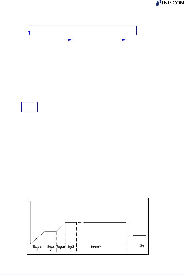
The SQC-310 stores the recipes, and provides the operating functions, required to control thin film deposition processes. A typical thin film deposition cycle is shown in Figure 1-7.
Figure 1-7 Typical Thin Film Deposition Cycle
1 - 7

SQC-310 Operating Manual
The cycle can be broken into three distinct phases:
Pre-conditioning (ramp/soak)
Deposition
Post-conditioning (feed/idle)
During pre-conditioning, power is supplied in steps to prepare the evaporation source for deposition. Once the material is near the desired deposition rate, material deposition begins.
During deposition, the PID loop adjusts the evaporation source power as required to maintain the desired rate. In Co-deposition, multiple films can be deposited simultaneously.
When the desired thickness is reached, the evaporation source is set to idle power. At this point the process may be complete, or deposition of another layer may begin.
1.8 Building a Process
This section presents a brief guide to building and running a simple one layer process. Chapter 2 covers instrument operation in much greater detail.
Table 1-5 Create a Film
Create a |
A film is a material to be deposited, and its associated deposition |
Film |
settings. Initially the list of films may be empty. |
|
Press Next Menu until the Film Menu SoftKey is displayed. Press |
|
Film Menu to view a list of stored films. Turn the control knob to |
|
scroll to an entry in the list that is currently labeled <Empty>. |
|
Press the Create SoftKey to create a default film at that location. |
|
Note the film number that you just created. For now, accept the |
|
default film parameters. |
|
Press Main Screen to return to the main screen. |
|
|
CAUTION
Be sure to exit to the Main Menu before powering the instrument down if you have made changes to settings. Your changes may not be saved otherwise.
IPN 074-550-P1B
1 - 8
IPN 074-550-P1B
SQC-310 Operating Manual
Figure 1-8 Film Select Menu
NOTE: Films are numbered from 1 to 50. Film names and process names can be changed by pressing the Edit Name SoftKey.
Now that we are sure that at least one film exists, we will build a simple single layer process using that film.
Table 1-6 |
Building a Layer |
|
|
|
|
Select |
|
Press the Process Menu SoftKey to view a list of processes. |
Process |
|
Turn the control knob to scroll to an entry in the list that is labeled |
|
|
|
|
|
<Empty>. |
|
|
Press the Create SoftKey to create a default process at that |
|
|
location. |
|
|
Press the Select SoftKey to make the selection the active process. |
|
|
|
Edit |
|
Press the Edit SoftKey to view a list of layers in the selected |
|
|
process. The layer list should be blank. |
|
|
|
Edit |
|
Press Insert New..., then scroll down the list of films to the film you |
Layer |
|
just created. |
|
|
Press Insert Normal to insert the selected film as Layer 1. The |
|
|
display returns to the Layer Select menu. |
|
|
NOTE: On SQC-310C, Insert Codep is also available to create |
|
|
Co-deposited layers. |
|
|
|
1 - 9

SQC-310 Operating Manual
Figure 1-9 Layer Select Menu
A process consists of one or more layers. Each layer can have a different film, or even multiple films (Co-deposition). For this example, we will stop with only a single layer. Layers are displayed as "Layer x.y", where x is the layer number and y is the source number assigned to the layer.
Table 1-7 Edit Layer
Edit |
|
With Layer 1.1 selected, press Edit to display the Layer Edit menu |
Layer |
|
for Layer 1.1. |
|
|
|
Figure 1-10 |
Edit Layer Menu |
|
IPN 074-550-P1B
1 - 10

|
|
SQC-310 Operating Manual |
|
|
|
|
Table 1-8 Editing a Setting |
|
|
|
|
|
Edit Menu |
To edit a setting in any menu, turn the control knob to scroll to the |
|
Operation |
desired setting, then press the Edit SoftKey. The cursor moves to |
|
|
the setting value, and the SoftKey functions change to show: |
|
|
Next: Store the parameter and move to next parameter for editing. |
|
|
Cancel: Stop editing and return the selected parameter to its |
|
|
previous value. |
|
|
Enter: Stop editing and save values for selected parameter. |
|
|
In Edit mode, adjust the control knob to set the desired parameter |
|
|
value. |
|
|
|
|
Edit |
Spend some time navigating through the Layer 1 parameters and |
|
Layer 1 |
editing values. Be sure to enter an Initial Rate and Final Thickness, |
|
|
and select a Source and Sensor(s). |
|
|
Press To Main to return to the Main Screen. |
|
|
|
We have completed the design of a single layer process.
IPN 074-550-P1B
1 - 11
SQC-310 Operating Manual
1.9 Depositing a Film
NOTE: You can simulate the steps below, without actually depositing a film, by going to the System Menu and selecting Simulate Mode ON. Simulate mode is useful for testing processes before applying power to the evaporation supply. See section 3.11 on page 3-19 for detailed System Menu information.
Table 1-9 Depositing a Film
Verify Sensor |
Press Next Menu until the Sensor Info option is shown. |
Operation |
Press Sensor Info to display the quartz sensor readings. Sensor 1 |
|
|
|
should be ON and display a % life of over 50%. If not, check your |
|
sensor connections (see section 1.3 - section 1.5), and refer to |
|
Min/Max Frequency (System Menu, see section 3.11). |
|
Press Exit to return to the main screen. |
|
|
Show |
Press the Next Graph SoftKey until the graph shows Power (% vs. |
Power Graph |
Time). |
|
|
Verify Output |
Press the Next Menu SoftKey until the Auto/Manual SoftKey is |
Operation |
displayed. Now press Auto/Manual until Manual/Auto is displayed. |
|
Press Start Layer to begin deposition in manual mode. |
|
Slowly turn the control knob to increase the control voltage to your |
|
evaporation supply. Verify that the Power(%) reading for Output 1 |
|
(lower right, below graph) approximates the actual output of your |
|
evaporation supply. If not, check your hookup (see section 1.3 - |
|
section 1.5), and refer to Scale Voltage (section 3.11.3.2). |
|
|
CAUTION |
|
|
|
|
|
|
|
|
|
|
Observe the output power versus your |
|
|
|
|
evaporation supply’s actual output. If |
|
|
|
|
there is a problem, press the Stop |
|
|
|
|
SoftKey immediately. |
|
|
|
|
|
|
|
|
|
||
Enter |
Press the Next Menu key until the Manual/Auto SoftKey is shown. |
|
||
Auto Mode |
Press Manual/Auto to change the SoftKey display to Auto/Manual. |
|
||
|
This places the output under PID deposition control. |
|
||
|
Press Stop at any time to halt deposition and set output power to |
|
||
|
zero. |
|
||
Please take time to review the remainder of this manual for detailed operational, programming, and safety information.
1 - 12
IPN 074-550-P1B

IPN 074-550-P1B
SQC-310 Operating Manual
Chapter 2
Operation
2.1 Introduction
This chapter describes common tasks associated with operating the SQC-310. It assumes that you understand basic operation of the menus and parameter setup as described in Chapter 1, Quick Start. Detailed definitions of each parameter can be found under the appropriate menu description in Chapter 3, Menus.
2.2 Definitions
Several terms will be used repeatedly throughout this manual. It is important that you understand each of these terms.
Material: A physical material to be deposited. A database of 100 materials is stored in the SQC-310. Three parameters completely define a material: Name, Density, and Z-Ratio (also called Z-Factor). A table of common materials, their densities, and Z-Ratios is listed in Appendix A.
Film: A film describes in detail how a material will be deposited. It includes the material definition and all of the preconditioning, deposition, and post conditioning variables necessary to accurately deposit the material. Because the film definition does not include rate and thickness information, a single film can be used in several different layers and processes. The SQC-310 stores up to 50 films.
Layer: Layers are the basic building blocks of processes. A layer consists of a film and the thickness and rate setpoints for that stage of the process. Layers also define which outputs and sensors will be used at that point in the process. Co-deposition of multiple films occurs when more than one output is active during a layer.
Process: A process is a sequence of layers to be deposited. The SQC-310 can store up to 100 processes, consisting of a total of 1000 layers.
Phase: A step in the deposition cycle. Preconditioning phases include Ramp 1, Soak 1, Ramp 2, and Soak 2. Deposit phases include indexer rotate, shutter delay, deposition, and deposition rate ramps. Post-conditioning phases include Feed Ramp, Feed, and Idle Power.
Figure 2-1 Phase
2 - 1
SQC-310 Operating Manual
2.3 Defining a Film
A film is a material to be deposited, plus all of its associated setup parameters. Keep in mind that a film can be used in multiple layers, or even multiple processes. Editing a film’s parameters will cause changes to every location where the film is used.
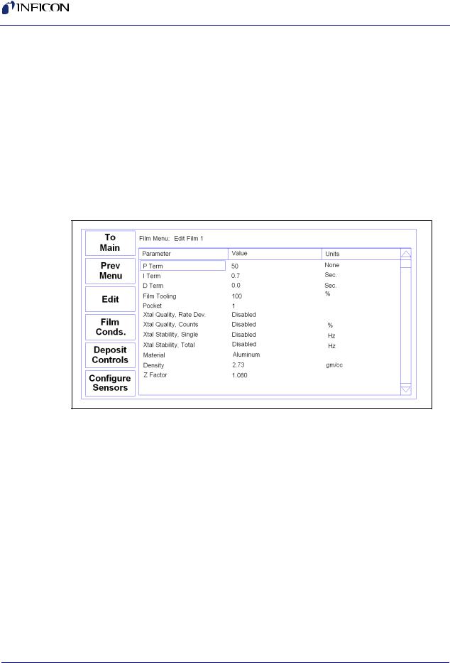
To define a film, press Next Menu until Film Menu is shown (Menu 3). Press Film Menu. A list of 50 films (or <Empty>) will be displayed. To define a new film, scroll to <Empty> and press Create. To change the name of a film, scroll to the film and press Edit Name. Scroll through the character set and Insert each character for the film name. Press Save to return to the Film Menu. Press Edit to display the parameters for this film.
Figure 2-2 Film Edit Menu
P Term is the proportional gain, which is the % process rate change divided by the % input power change. The I Term (integral) sums the rate deviations over time to more accurately achieve the rate setpoint. The D Term (derivative) speeds response to sudden changes in rate. Volumes have been written on determining the proper PID settings. See section 2.8 on Loop Tuning later in this chapter for a common PID loop tuning procedure. Start with P=25, I=.5, D=0.
Film Tooling adjusts for differences in actual versus measured thickness for this film (material). This parameter is seldom used, but can adjust for material specific dispersion patterns. See Xtal Tooling in the System menu for the more commonly used tooling correction.
Pocket selects the source pocket used for this film. This parameter requires that the System Menu, Source Setup be configured for an indexer (Sensors and Sources Menu, see section 3.11.3).
The next chapter will cover Crystal Quality and Stability. For initial operation leave Quality and Stability disabled.
2 - 2
IPN 074-550-P1B
IPN 074-550-P1B
SQC-310 Operating Manual
With Material highlighted, press Edit to scroll through the list of available materials. Select the desired material and press Enter. You could also change the Density and Z-Ratio for the selected material, but it is unlikely those values are wrong. You cannot add materials, but you can edit the Name, Density, and Z-Ratio of one of the 100 existing materials.
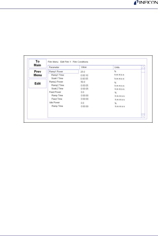
Film conditioning adjusts the output power level to achieve a desired material state before and after deposition. Press Film Conds to enter the film conditioning menu.
Figure 2-3 Film Conditioning Menu
Ramp1 starts at 0% power and increases the power during Ramp1 Time to the Ramp 1 power level. Set the Ramp 1 Power and Time to gradually bring the material to a near molten state. Set the Soak 1 Time to a value that will allow the material to homogeneously achieve that state. Ramp 2 is used to slowly bring the material to a power level that nearly matches the desired deposition power. Use Soak 2 to hold the material at that level until deposition (i.e., rate control) begins.
If you use wire feed to replenish material after deposition, set the Feed Power and times as required. The idle conditioning phase typically ramps output power back toward zero at the end of a process.
From the Film Conds menu, press Prev Menu to return to the main Film Menu.
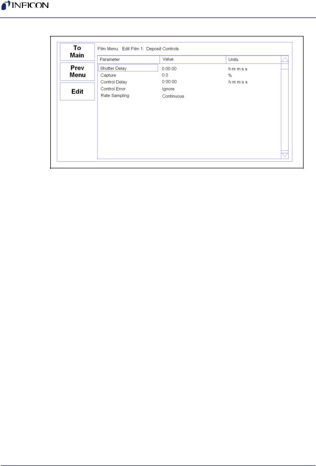
Now press Deposit Controls. The Deposit Controls menu contains parameters that modify operation during the deposition phase. See Figure 2-4.
2 - 3
SQC-310 Operating Manual
Figure 2-4 Deposition Controls Menu
Shutter delay causes the SQC-310 to delay opening the shutter until the process has stabilized at the desired deposition rate. Capture is the % rate deviation that must be achieved to open the shutter and go to the Deposit phase. Shutter delay is the maximum amount of time to wait for capture to be achieved. Set Shutter Delay and Capture to zero to disable this feature.
NOTE: During co-deposition, the SQC-310 waits for all films to achieve capture before moving to the deposit phase. If any film fails to achieve rate capture within its programmed shutter delay time, an error occurs.
When the Control Delay function is used, the control loop will not react to the rate for a set amount of time at the beginning of the Deposit state. This helps to eliminate overcompensation by the control loop due to rate spikes when the sensor or source shutter opens. Control Delay is the amount of time the SQC-310 will wait before the control loop takes over.
Control Error is a setting that instructs the SQC-310 what to do if it is unable to maintain the desired deposition rate (for example, out of material or a bad sensor). One of three actions is possible: Keep trying (Ignore), set power to zero to halt deposition (Stop), or maintain constant power (Hold) and extrapolate thickness from the last good rate reading. Until your process is known and stable, it is best to leave the Control Error setting on Ignore.
Rate sampling can extend sensor life in high rate processes. Select Cont (continuous) to disable rate sampling. A Time selection closes the shutter for a fixed time, then opens the shutter for a fixed time to sample the rate. Acc Based (accuracy based) sampling closes the shutter for a fixed time, then opens the shutter until the desired rate is achieved. Rate Sampling assumes a very stable process!
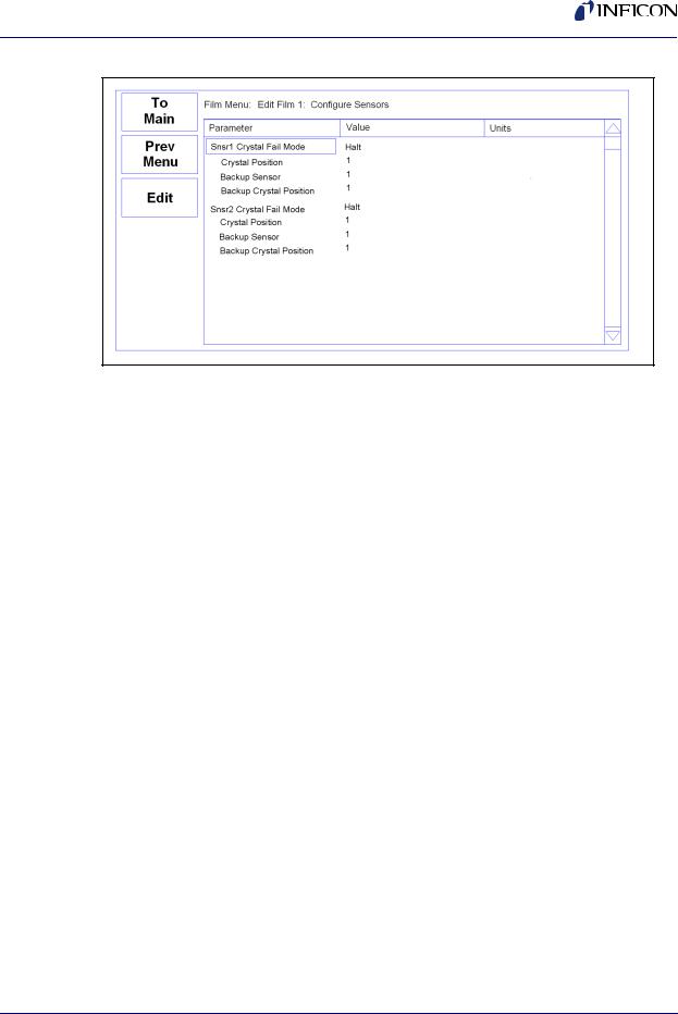
Now, from the main Film Menu, press Configure Sensors. This menu defines operation of the film when a sensor fails. See Figure 2-5.
2 - 4
IPN 074-550-P1B
SQC-310 Operating Manual
Figure 2-5 Configure Sensor Menu
IPN 074-550-P1B
Crystal Fail mode selects the action taken when a sensor crystal fails. Select Halt to halt the process on failure. Select Halt Last if multiple sensors are used for this film. Select Timed Power to enter Timed Power mode using the last good rate/power measurements. Select Switch to Backup to switch to a backup crystal.
The next three parameters define which position of a multi-crystal sensor is used as the primary, and which is the backup. The number of sensor positions displayed is determined by the sensor configuration on the Sensors & Sources screen of the System Menu.
2.4 Defining a Process
To define a process, press Next Menu until the Process Menu SoftKey is shown. Press Process Menu. A list of 100 processes (or <Empty>) will be displayed. To define a new process, scroll to <Empty> and press Create. A new Process# is added to the list of existing processes. Press Edit Name to change the process name.
Press Select, then Edit to display the sequence of layers and films that comprise the selected process. To add the first layer, press Insert New. Select a film from the films screen and press Insert Normal. To add more layers, scroll to below the last layer and press Insert New. Layers are always added above the selected layer.
To insert a layer in a sequence of layers, scroll to below the desired location in the layer sequence, and press Insert Normal. Select a film from the list and press Insert Normal to insert the new layer above the selected layer. The selected layer and subsequent layers will be shifted down.
HINT: When building a process it may be easiest to add a “dummy” last layer and keep inserting above that layer. When the process is complete, delete the “dummy” layer.
2 - 5
SQC-310 Operating Manual
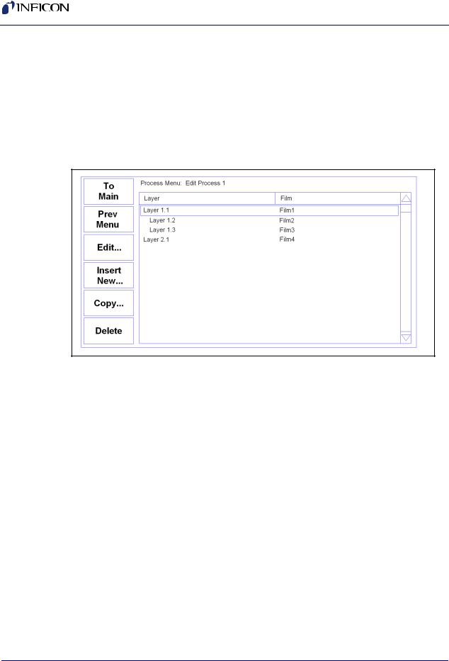
To add a Codeposited film to an existing layer, scroll to below the desired Co-deposition layer. Press Insert New, select the desired film, then press Insert CoDep. The Codeposited film will be inserted in the layer above the selected layer, and indented to show that it is a Co-deposition film. CoDep is available only on the SQC-310C.
Figure 2-6 shows two films being Codeposited with Film1, then a fourth film being deposited as an additional layer. While layers are always numbered sequentially, the films are sequential only for this example. Any film can be used in any layer.
Figure 2-6 Edit Layer Menu
To delete a layer, highlight it in the Layer Select menu and press Delete.
To move or duplicate a layer, highlight it in the Layer Select menu and press Copy. On the Paste menu, press Paste to replace a layer. Press Insert Normal or Insert CoDep to insert it above the highlighted layer. A copy of the layer is saved to the cut/paste clipboard memory.
NOTE: Once a film is assigned to a process layer, you cannot change the film. Instead, cut the layer, then insert a new layer and select the desired film.
IPN 074-550-P1B
2 - 6
Loading...